Abstract
Deep-sea decarbonization remains an enigma as the world scrambles to reduce global emissions. This study looks at near-term decarbonization solutions for deep-sea shipping. Pathways are defined, which are appealing to ship owners and major world economies alike. The economic and environmental viability of several of the most advanced near-term technologies for deep-sea decarbonization are revealed. The environmental analysis suggests the necessity of new emission intensity metrics. The economic analysis indicates that the carbon tax could be a great motivator to invest in decarbonization technologies. Standalone decarbonization technologies can provide a maximum of 20% emissions reduction. Hence, to meet IMO 2050 targets of 50% emissions reduction, several solutions need to be utilized in tandem. This study reaches the conclusion that alternative fuels are the crucial step to achieve a net zero carbon economy, although bunkering, infrastructure, and economic hurdles need to be overcome for the widespread implementation of carbon-neutral fuels.
1. Introduction
The global economy relies on the shipping industry, with approximately 90% of the world’s trade being carried out via deep-sea shipping [1]. Consequently, in 2018, 2.89% of the world’s anthropogenic CO2 emissions originated from deep-sea shipping, amounting to almost one billion metric tons of CO2 emissions. In the final report released by the International Maritime Organization (IMO) in 2020, it was estimated that without repercussive measures, marine Green greenhouse gas (GHG) emissions would increase by 130% by 2050 [2]. With the drastic rise in marine GHG emissions, the IMO passed a resolution in 2018, aiming to reduce GHG emissions from the marine sector by at least 50% by the year 2050, relative to 2008 [3]. With stringent regulations already in place for NOx and SOx emissions, the IMO is pushing hard towards energy-saving technologies and alternative fuels to counter CO2 emissions as well. In 2021, the EU released its aggressive “fit for 55” policy for maritime decarbonization, which aims to cut 55% GHG emissions, relative to 2008, by 2030 and a fully carbon-neutral maritime industry by 2050 [4].
The shipping industry is currently dominated by heavy fuel oil (HFO), which is the cheapest, most polluting, and widely available fuel in the marine sector [5,6]. HFO combustion releases CO2, NOx, SOx, and particulate matter (PM) emissions, which are the basis for the application of global environmental policies against the marine sector. The ramifications of HFO emissions are concerning, with almost 400,000 premature deaths in Europe caused by PM as a direct result of shipping industry HFO combustion [7].
Racing against the repercussions of inevitable global policy tightening, the marine industry is seeking commercially deployable decarbonization technologies to reduce the sector’s carbon footprint and play a part in the collective global effort to avoid an irreversible climate catastrophe. There is growing interest in renewable hydrogen, ammonia, methanol, and biofuels as HFO alternatives [8]. Alternative energy technologies have also piqued the interest of many researchers, with reported fuel savings of up to 30% for deep-sea vessels [1,9]. Bouman et al. [9] conducted a review of different decarbonization technologies, compiling a performance table of each decarbonization technology. They found that rather than a single technology application, multiple technologies in tandem are better suited for deep-sea decarbonization.
1.1. Deep Decarbonization Using Carbon-Neutral Fuels
In recent years, a large amount of literature has emerged as scientists explore the possibility of alternative fuels in the shipping industry. In the past two decades, LNG has emerged as an alternative fuel, especially since it significantly reduces NOx emissions and almost eliminates SOx and particulate matter (PM) [10,11]. Statistically, LNG can reduce NOx, SOx, PM, and CO2 emissions by 86%, 98%, 96%, and 11%, respectively [12]. As of 2022, there are 286 LNG-fueled vessels, with an additional 489 on order [13]. As reported by Yoo [14], LNG seems to be a more cost-effective fuel for vessels where low capital investment is required, such as CO2 carriers. However, this claim is refuted by Balcombe et al. [15], who pointed out that LNG is only cost effective if the fuel price remains consistently below the price of traditional fossil fuels. Hwang et al. [16] found that switching marine oil with LNG produced 12% less CO2 emissions. However, the methane slip, which ranges between 2 and 5.5 g/kWh depending on engine type, from the LNG engine was not negligible. Hence, they suggested using LNG as a transition fuel to fully carbon-neutral fuels after 2030.
Alternative fuels derived from biomass are classed as “biofuels” and include a range of different types of fuels such as bio-methanol, bio-diesel, bio-oil, etc. [17]. Biofuels can be used as a drop in fuel, hence requiring little modification to the engine. Although biofuels are very effective in reducing GHG emissions, they are not as readily available as fossil fuels and have much higher costs, especially for advanced biofuels [1]. The GHG emissions reduction potential of biofuels depends on the lifecycle of the crops, harvesting techniques, location, and processing, all of which have an environmental impact [9]. A life cycle analysis (LCA) was conducted by Stathatou et al. [18] on a dry bulk vessel, using a 50:50 blend of biodiesel and marine gasoline oil. Citing global availability and cost challenges, they concluded that the well to wake (WTW) emissions were approximately 40% less than that of conventional fuels, with no engine modifications. Ammar [19] proposed using a blend of methanol with marine diesel oil in a dual fuel methanol–diesel engine, observing a reduction of 18% in CO2 emissions, with a 28% increase of bunkering and fuel costs. Bio-methanol occupies almost the same volume as LNG, is liquid at ambient temperature, and can be much more easily stored than LNG [20]. Bio-methanol as a marine fuel is a very attractive option. Liu et al. [21] and Svanberg et al. [22] indicated that the only hindrance in the widespread adoption of methanol as a marine fuel is the unreliability of land-based bio-methanol plants in ensuring a constant supply of methanol. Additionally, they [21] point out that replacing 50% of the bunkering capacity of HFOs with bio-methanol would require 22.6 million hectares of dedicated land use. Comparatively, the UK has only 17.2 million hectares of agricultural land [23].
Hydrogen and ammonia are both zero-carbon fuels that can be used in combustion engines or in fuel cells for electric propulsion [24,25,26,27,28,29,30]. MAN Energy Solutions [31] is currently working on developing dual fuel hydrogen and ammonia engines. In terms of fuel cells, green-hydrogen fuel cells have been successfully demonstrated to have less GHG emissions than diesel ICEs. Madsen et al. [32] investigated a green-hydrogen PEMFC-driven research vessel, achieving a 91% reduction in GHG emissions, albeit with a high capital cost. Ghenai et al. [33] investigated a green-hydrogen PEMFC energy system onboard a cruise ship, reducing emissions by 9.84%. Using ammonia with PEMFCs is undesirable since it requires ammonia cracking (splitting the ammonia into N2 and H2) [34], while SOFCs can convert ammonia into H2 and N2 during operation. Wu et al. [35] performed a comparative study on ammonia SOFC and diesel ICE and found that the GHG emissions could be reduced to zero with fully electric propulsion powered by green ammonia fuel cells. Kim et al. [36] found that while a reduction of 83–91% could be achieved in GHG emissions, the cost of running a vessel on ammonia SOFC would be 5.2 times higher than conventional ICEs. It is notable that hydrogen and ammonia are only viable when produced from renewable energy since the production of blue/gray hydrogen and ammonia is very carbon intensive [37,38]. However, renewable hydrogen and ammonia production is currently uneconomical [39,40]. This, along with low volumetric energy densities [41], cryogenic storage temperatures, and high-pressure requirements [42], has severely limited the development of bunkering infrastructure, hindering the use of hydrogen and ammonia in the shipping industry.
Comparative studies are an important indicator to determine the relative performance of alternative fuels. In a review conducted by [43] on alternative fuels, they discovered that from the year 2000, the research on alternative fuels has increased by an annual growth rate of 15.8%. The current trend of research suggests that while LNG has been the focus of most researchers, there has been a shift towards cleaner alternative fuels, such as hydrogen, ammonia, and methanol. However, the inefficiencies regarding the production of alternative fuels, the lack of bunkering infrastructure, and cost parity with HFOs needs to be addressed for alternative fuels to be adopted industry-wide.
1.2. Looking beyond Fuel: A Near-Term Solution
Deep-sea decarbonization might be the most difficult to achieve, owing to high energy requirements for vessels. These energy requirements may, in part, be met by alternative energy sources such as wind and solar. Solar energy has been found to be inconsequential in decarbonizing long-haul vessels [44]. On the other hand, wind-assisted ship propulsion (WASP) technologies provide proven 1–30% fuel savings [9]. From our intensive literature review, it was found that the most efficient WASP technology currently available is the Flettner rotor, providing CO2 reductions of up to 25–30% whilst having low investment costs and high return on investment (ROI) [45,46,47,48].
In terms of hydrodynamics, many studies have been conducted on hull design and optimization, the use of lightweight materials, hull coatings, and vessel size [49,50,51,52,53]. Air lubrication is a new technology in this regard, which works by using compressors and blowers to blow air bubbles underneath the hull, effectively reducing the viscosity friction with the water. Commercially available air lubrication systems [54] provide fuel savings of up to 8%, depending on ship speed.
The electrification of deep-sea vessels is another method to reduce emissions and may include complete or partial electrification. With the UK’s renewable electricity production nearing 45% in 2022 [55], batteries could reduce marine GHG emissions. However, battery size constraints pose an issue in deep-sea shipping [56]. Kersey et al. [57] conducted a study using the most technologically advanced battery systems currently available and concluded that battery-operated deep-sea vessels would only be cost effective up to a 2000 km voyage length. This study [57] reaffirmed the stance of Minnehan et al. [58] that battery-powered vessels do not have enough volumetric energy density to support long-haul voyages and are only suitable for short-duration trips.
Another technology that could potentially be used to reduce GHG emissions is the carbon capture and storage (CCS) technology. Although widely used in land-based applications (coal power plants, oil refineries, steel industry, etc.), CCS technologies are a new concept in the marine industry. Several studies concluded that the main hindrances to CCS technologies onboard a marine vessel are the cost and size requirements [59,60,61]. Recently, Wärtsilä [62] announced the building of a research center in Norway, where maritime CCS technology would be developed on a pilot scale up to 2024. They expect to release the CCS technology by 2025.
1.3. Outline
The applicability of decarbonization technologies in the marine industry has a rich literature basis. Although researchers have performed comparative analysis with different technologies and alternative fuels with the baseline case using HFOs, little regard has been given to ship owners who recently purchased ships and will not be willing to invest more money. There seem to be no clear-cut guidelines from either the IMO or the EU regarding the implications that come with the application of the proposed carbon tax, whether a financial levy on non-conforming ships or a blanket ban on ships that do not meet GHG requirements. The novelty of this study lies in the use of alternative fuel technologies and alternative energy technologies, readily available or available in the near term, to ascertain the best way forward to achieve deep-sea decarbonization. Most previous studies have not considered ammonia and hydrogen fuel cells in long-haul deep-sea shipping, and the economic analysis lacks consideration of the fuel storage tank. To the best of the authors’ knowledge, no such studies are available that perform a comparative study on alternative fuels, fuel cells, batteries, CCS, and WASP technologies. Additionally, the existing literature lacks in providing a direct link between the effect of environmental impact on economic variables. We use eleven scenarios (using real ship operational profiles and technology performance data) to encompass a wide range of deep-sea decarbonization technologies, including alternative fuels (LNG, hydrogen, and ammonia) being utilized in engines and fuel cells, as well as alternative energy technologies (batteries, WASP, and air lubrication) and emission abatement technologies (CCS).
2. Methodology
This section examines the system configuration, which then serves as the foundation for the performance, environmental, and economic models. The establishment of a baseline model is vital for long-haul ships, and the route plays an important part. In this regard, the first section defines the case ship and the route specifications. Equally important is the ship power demand profile, which has also been specified in this section. This is shown in the first section of Figure 1. The second section defines the scenarios and outlines the system configuration of each scenario. This is shown as scenario identification in Figure 1, and in this section, Siemens Simcenter 2022 and Simulink 2022 were used to predict technology partial load performances. The third section outlines the performance, economic, and environmental models. Here, MATLAB 2022 was used to build the fuel economy, environmental, and economic models with spreadsheet data input from Microsoft Excel. The methodology is concluded with the fourth section, which details the assumptions and key input variables necessary for model functionality. Figure 1 shows the concept methodology (Sections 1–3) and the analysis stemming from it (Sections 4–6).
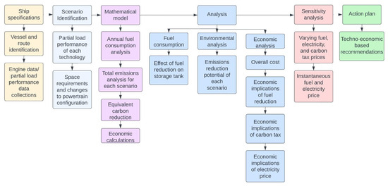
Figure 1.
Conceptualization of the methodology.
2.1. Case Ship and Route Specifications
The case ship is an Aframax tanker, built in 2021, measuring 250 m in length and weighing 115,000 DWT. The considered ship has undergone sea trials and is now in service; one of the most common routes it travels on is from Rotterdam, Netherlands, to Newark, New Jersey, United States [63]. It is one of the most common routes for transatlantic trade; hence, it is chosen for this case study. The route details can be accessed via [64] by setting a service speed of 13 knots. The main ship parameters and engine data were provided by [65]. The main engine for the baseline ship is the MAN B&W 6G60ME-C10.5 (TIER III), designed by MAN Energy Solutions. Three sets of auxiliary engines are installed on the ship, each capable of producing 1200 kW of power [66]. The engine performance curves and the ship power demand profile are shown in Figure 2. Figure 2a shows the specific fuel oil consumption (SFOC) and the exhaust gas specifications, and it can be seen that the engine has the highest efficiency between 60 and 70% engine load (8000–9000 kW). The highest efficiency is achieved at the lowest SFOC. That is why the vessel runs at this engine load for the majority of the voyage, as shown in Figure 2b. The data provided by [65] correspond to the engine performance data found in the literature [67].
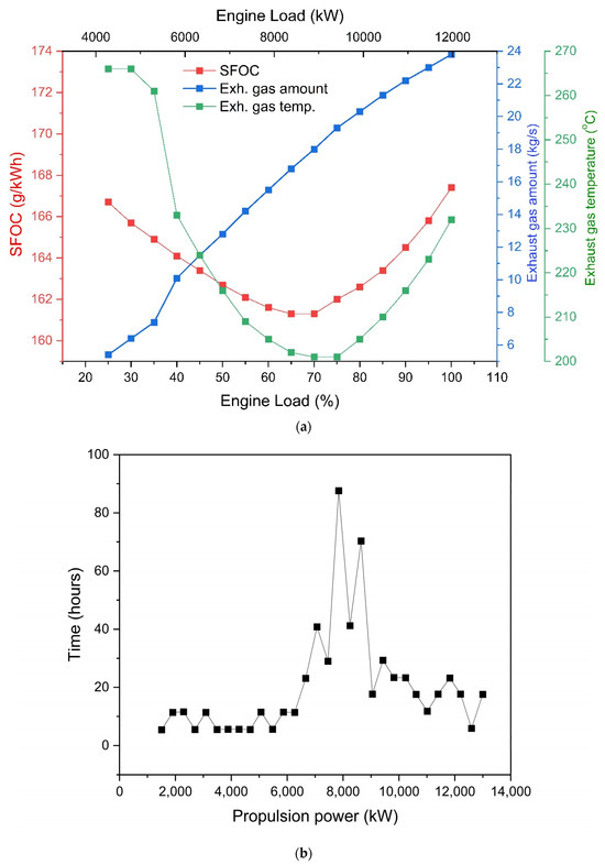
Figure 2.
Engine performance maps. (a) VLSFO fuel consumption profile [65]; (b) propulsion power demand [65].
2.2. System Configuration
Each scenario case is summarized in Table 1. The Aframax tanker comes equipped with a two-stroke diesel engine, which is LNG-ready, according to [65]. Scenario A and B employ 10% biodiesel blend and LNG fuel, respectively. For scenarios C and D, one auxiliary engine in each case was replaced with batteries and six hydrogen PEMFCs, respectively. Due to battery size constraints, the battery is utilized during port operations. Scenario E and F make use of alternative energy in the shape of Flettner rotors, with each case making use of two rotors on board. The Flettner rotors aid in ship propulsion, causing a reduction in fuel consumption via less load on the main engine. CCS adsorption technology is applied for scenarios G and H. In scenario G, an additional ammonia refrigeration loop is applied for CO2 liquification for storage, whereas in scenario H, LNG cryogenic energy is utilized for this purpose. The system design and space requirements of the CCS system can be found in [60]. This results in a lower cost for the CCS system in scenario H. Scenario I works in a similar fashion to scenarios E and F, reducing the load on the main engine with a reduction in viscosity drag between the vessel’s hull and the water by introducing a film of air bubbles as lubricant. Scenario J and K make use of solid oxide fuel cells (SOFCs) by replacing one auxiliary engine, respectively. The battery pack, PEMFC, and SOFCs are sized to meet the power requirements of one auxiliary engine.

Table 1.
Scenario descriptions based on different decarbonization technologies.
2.3. Mathematical Models
2.3.1. Fuel Consumption Calculations
The fuel consumption model employed in this study uses actual sea trial and engine data, including the specific fuel oil consumption (SFOC) (g/kWh), engine power with respect to time spent sailing at this power, and the time (sailing hours at specific power rating, port operations, manoeuvring, and berthing). Equation (1) is used for the fuel consumption calculation for each case.
Here, M(fuel) is the annual fuel consumption, P is the power, and dt is the time. For the fuel cell scenarios, annual fuel consumption (M(fuel)PEMFC,SOFC) is calculated based on the requirements of baseline auxiliary engine power ():
2.3.2. GHG Calculations
To analyze the complete effect of the vessel on the environment, it was necessary to calculate the GHG emissions based on the WTW lifecycle [72]. Several factors have been developed by researchers to correctly predict the WTW GHG emissions. These factors are based on the fuel and engine type being utilized by the vessel. For this study, the baseline engine can be classed as a slow speed diesel, the LNG DF engine as a diesel-cycle LNG, and the auxiliary engines running on diesel and LNG can be classed as a medium speed diesel and medium speed DF LNG, respectively. The factors are shown in Table 2 [73].

Table 2.
GHG emissions WTW factors [73].
Equations (3) and (4) were used to calculate the GHG emissions. For scenario cases G and H, since there are no fuel savings, the GHG emissions are calculated by subtracting the annual CO2 saved due to the CCS technology.
Here, F is the GHG factor.
2.3.3. EEDI and CII Calculations
The Energy Efficiency Design Index (EEDI) is an-IMO approved method to calculate the mass of CO2 emitted per transport work for newly built ships [74]. EEDI only considers the CO2 emitted by vessels and not the other GHG emissions. The carbon intensity indicator (CII) is an operational efficiency indicator that measures carbon intensity over time [75]. CII has not yet been finalized by the IMO, but several equations have been provided by the IMO to calculate the CII. The equation for calculating the EEDI and the definition of each term can be obtained from [76]. The equation for the CII is given below [75]:
For the calculation of the EEDI for scenario cases C to I, there is no regulation from the IMO for adjustments to the EEDI formula. Hence, a factor was developed to calculate the EEDI for each case.
Then, the new EEDI can be calculated as
The same factor was used to calculate the CII for each case. Hence, the CII would become
2.3.4. Economic Calculations
The economic implications of decarbonization technologies stem from the total vessel powertrain cost, which includes engine cost, the operating costs (including fuel, maintenance, etc.), and the additional cost of the decarbonization technologies. The product lifetime was assumed to be 25 years, equal to the average lifetime expectancy of the vessel.
The capital investment is first converted to the amortized annual investment cost (), expressed as [77]
where is the annual interest rate, is the capital cost, and is the engine lifetime.
The annual operating and maintenance cost () depends on each scenario case and is calculated using Equation (10) [77]:
Some decarbonization technologies, such as batteries and CCS systems, have a shorter lifespan than the main engine lifespan. Hence, the replacement costs must be accounted for in the economic calculations. The annualized replacement cost () is defined as follows [77]:
Here, is the year of replacement.
To calculate the relative annual revenue generated, it was assumed that the power produced by the vessel would be converted to electricity and sold to the national grid at the current cold ironing prices. Hence, the annual revenue, , is given by [77] as follows:
where is the unit price of electricity ($/kWh), while is the annual energy production (kWh) by the vessel’s powertrain.
According to Duan and Zhang [78], carbon tax application in the marine industry is imminent and needs to be accounted for when calculating the net annual income [77]:
Here, j is the year in the vessel’s lifetime.
The discounted payback period (DPP) is defined as the year the initial investment is covered and the product starts to generate profit and is calculated as [77]
The levelized cost of electricity (LCOE) is the cost of producing one unit of electricity via the vessel’s powertrain. It can be calculated using the sum of total annualized costs and the annual electricity production and is expressed as follows [77]:
Here, We is the annual electricity production.
2.4. Model Assumptions and Key Inputs
Several input variables were required to be put into the model. Table 3 shows the fuel price and properties. Since there are no fuel savings for the CCS system, neither does it contribute to the powertrain; it is assumed that the captured CO2 would be sold at the same rate as the carbon tax. Only a fixed amount of exhaust gas would pass through the CCS system so that the system was completely self-sufficient in terms of thermal energy requirements and to keep the size of the system as compact and small as possible. The CCS system was based on the studies conducted by [60,61]. For the battery scenario, it is assumed that the battery is charged with 100% renewable electricity. For the fuel cell scenarios, the fuel cells are containerized as 100 kW × 6 modules. The SOFC efficiencies are set at 50%, and PEMFC efficiency is set at 43% [79]. Figure 3 shows the historical fuel and electricity prices. It is interesting to note that the fuel prices do not show a specific trend but are rather heavily influenced by the geopolitical climate.

Table 3.
Fuel properties.
It is pertinent to note that since these are input variables, the validity of the model and the methodology would still be upheld, even in the case of drastic changes to fuel prices. Additionally, this model can be adapted to any marine vessel and any route if the engine data, fuel consumption, propulsion power demand, and exhaust gas analysis are provided.
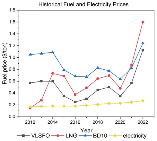
Figure 3.
Historical fuel and electricity price data (in the month of July every year) [87].
3. Results and Discussion
The above-presented methodology was applied to the case of an Aframax tanker. Different scenario cases were considered, as shown in Table 1. The environmental benefits of applying different decarbonization technologies are discussed based on reduced fuel consumption and reduced GHG emissions. The economic implications of the decarbonization technologies are discussed on a vessel basis rather than a standalone technology basis. This provides a better overview of the overall cost repercussions on a system level.
3.1. Fuel Consumption Analysis
When evaluating a vessel’s fuel consumption, it is important to consider both the fuel volume and the fuel mass. Each fuel has different volumetric energy densities and hence different storage volumes for the same amount of energy supplied. Both have economic implications, as the fuel is sold on a mass basis, whereas the storage tank size and cost are decided on a volume basis. Another way to look at the fuel consumption of any vessel would be to determine the overall annual energy consumption of the vessel. The lower calorific value (LCV) is the amount of energy available in per kilogram of a fuel. With LNG having the highest LCV, it is only logical that the mass fuel consumption of the DF scenario case is less than that of the VLSFO scenario case. However, the volumetric energy density of LNG is lower than VLSFO, hence requiring more storage volume as compared to VLSFO. Figure 4 shows the comparison of different fuels for each scenario case in terms of both fuel mass and fuel volume. An observation that can be made is that the Flettner rotor provides the highest fuel savings, whereas the battery and fuel cells do not provide significant fuel savings. Hence, from a purely fuel consumption standpoint, the Flettner rotor is the front runner in the race for the most efficient decarbonization technology. Of course, in the case of the CCS technology, no fuel savings were expected, as the CO2 capture is initiated post-combustion. However, it is important to note that the storage of the captured liquid CO2 must be considered during the design stage, as it would be stored at a high pressure and low temperature with a different standard compared to LNG storage tanks.
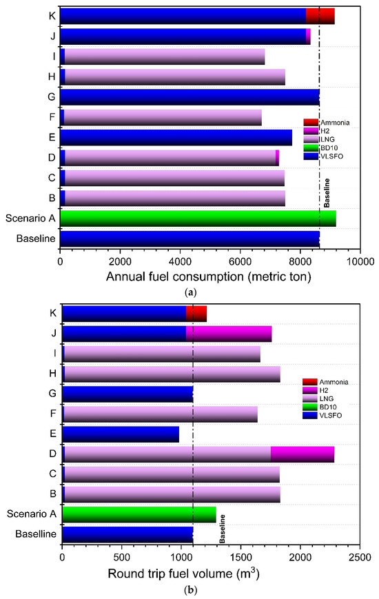
Figure 4.
(a) Round trip fuel volume; (b) annual fuel consumption.
A takeaway from this analysis is that when considering the use of alternative fuels, the volumetric energy density should be of the highest concern. With discussions surrounding hydrogen or ammonia-fueled DF engines, the biggest concern should be fuel tank spacing considerations. This is because ammonia has half the volumetric energy density of LNG, while hydrogen has one-third [43]. The same goes for methanol, which has two-thirds the volumetric energy density of LNG. For reference, the volumetric energy densities of VLSFO, LNG, liquid hydrogen, liquid ammonia, and methanol are 40 MJ/L, 22.5 MJ/L, 8.5 MJ/L, 11.5 MJ/L, and 16 MJ/L, respectively [88].
3.2. Emissions Reduction Potential of Deep-Sea Decarbonization
CO2, NOx, SOx, and PM are common byproducts of fossil fuel combustion, while additional methane emissions have to be considered in the case of LNG engines. With all other combustion byproducts causing greater environmental damage than CO2 [73], it is imperative to monitor all pollutants individually rather than just using CO2 reduction as the benchmark for decarbonization. Equally important is to note the effect each pollutant has over a specific time period. While some pollutants cause greater short-term harm, their effects mellow out over a longer period of incubation. Methane, in this regard, is particularly noteworthy, being 87 times more potent than CO2 over 20 years while being 36 times more lethal over a hundred-year period [2,73]. This is evident from the results of this study, shown in Figure 5a, where the disparity between the baseline scenario and the DF scenario cases stems from the emission of methane in the case of GWP20. The outlook improves over the hundred-year incubation period and hence raises the question as to which time horizon and climate metric be adopted as a standard for decarbonization technology evaluation.
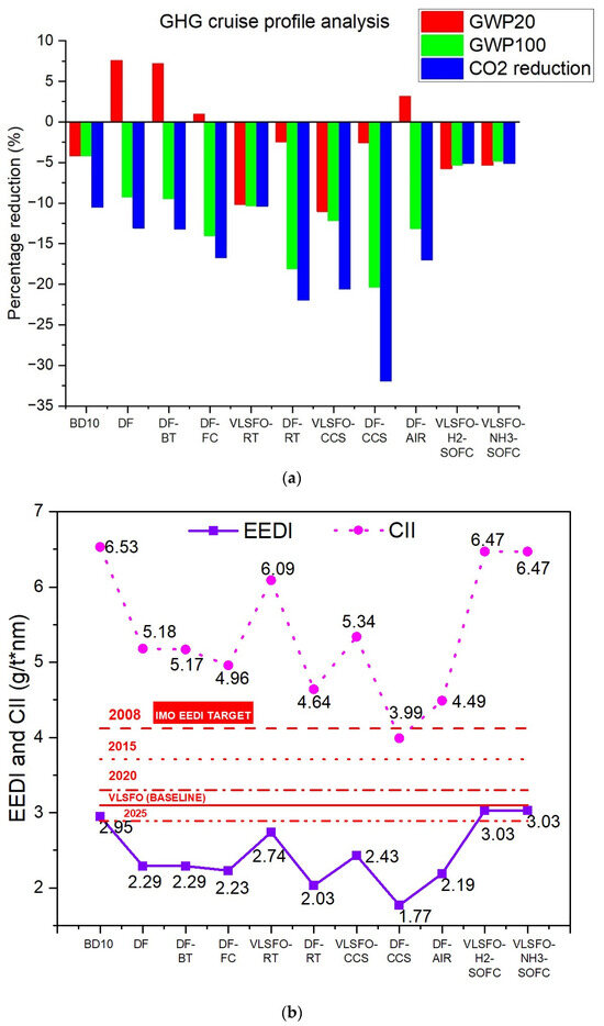
Figure 5.
(a) GHG emissions analysis; (b) EEDI and CII analysis.
Whilst the results are self-explanatory, it may be surprising for some to see that the battery adds little value to the GHG reduction objective. This is contradictory to the research conducted by Ref. [57], who achieved a 51% decrease in CO2 emission intensity if the UK grid carbon intensity is considered. However, Ref. [57] considered a fully electric vessel with a maximum voyage length of 2000 km for it to be cost effective. In this study, the battery was only utilized during port operations. Normally, the battery pack is used to make sure the engine runs at peak efficiency, with the battery providing the rest of the required propulsion [89]. The battery sizing was performed based on the available space for this case ship. Comparatively, the fuel cells show promising reductions in GHG emissions even with a partial load application. One of the most important observations that can be made from this life cycle analysis study is that the Flettner rotor provides almost the same environmental benefit to the baseline scenario as does switching to LNG as the fuel. This is incredibly important, as LNG is the most carbon-intensive fuel among all alternative fuels [9]. This signifies that less carbon-intensive alternative fuels will always have a higher deep-sea decarbonization potential, at least from an environmental perspective, than alternative energy technologies.
The current carbon intensity metric for deep-sea vessels adopted by the IMO is the EEDI, while the CII regulations, reported to be an upgrade to the EEDI [75], are yet to be determined. Whilst the authors believe that the EEDI is an outdated method to determine a vessel’s environmental impact since it only considers CO2 emissions, the analysis was performed to reaffirm the authors’ opinions. In Figure 5b, the horizontal red lines show the IMO-specified EEDI targets for ship owners. Let us consider the DF and the VLSFO-RT scenario cases. While the GWP100 outlook is slightly better for the VLSFO-RT case, the EEDI is higher than the DF case due to higher CO2 reduction in the case of DF. This inherent lack of consideration on the part of other pollutants results in an inaccurate depiction of a vessel’s carbon intensity. These observations are in line with those made by Attah et al. [74], who concluded that the EEDI could not accurately predict the environmental impact of LNG-fuelled vessels and recommended that the IMO include methane slip into the calculation of the EEDI. Lindtsad et al. [90] passed a similar judgement while investigating the use of batteries for deep-sea shipping. They discovered that the EEDI always exaggerated the decarbonization potential of technologies due to shortcomings such as the assumption of a uniform engine load during the entire voyage. Based on the results of this analysis and that conducted by other researchers, the authors recommend the IMO adopt a GHG screening policy, which accounts for all post-combustion pollutants. The same stands true for the CII, although the IMO may yet provide certain considerations in the calculations for the CII. The bottom line is that there need to be regulations put forward by the IMO, which provide a vessel’s emission levels in terms of complete GHG emissions.
3.3. Cost Parity with HFOs
The economic analysis of every system stems from the capital investment and the annual operational and maintenance costs of the system. A breakdown of the CAPEX for each decarbonization technology, inclusive of the powertrain, is shown in Figure 6. Due to the commercial sensitivity of such data, the analysis was conducted compared to the cost of the powertrain of the VLSFO scenario. As discussed in Section 3.1, the volumetric energy density of each fuel is different, and some technologies provide fuel savings, as was evident from Figure 4. Thus, alternative fuels add extra cost in terms of fuel storage, while the HFO tank size remains constant as newly built ships are disregarded. Engine modifications lead to an increase in CAPEX for the DF scenario cases, with each decarbonization technology piling on top. As described in Section 2.4, the CAPEX of the CCS system depends on the choice of fuel and mode of CO2 liquification. With LNG cryogenic energy available for CO2 liquification in the DF-CCS scenario case, the CAPEX is significantly reduced compared to the VLSFO-CCS scenario case, in which the additional ammonia refrigeration loop leads to a high CAPEX. For the hydrogen PEMFC and SOFC, hydrogen storage cost dominates the CAPEX.
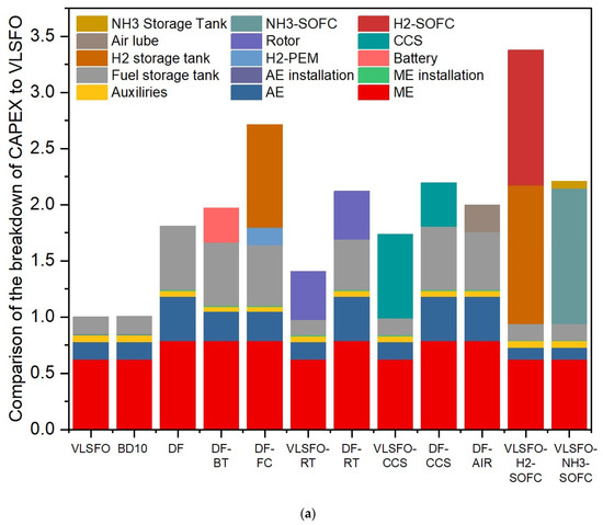
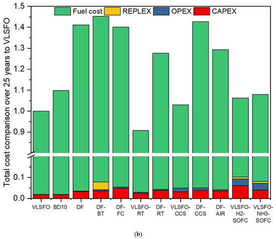
Figure 6.
(a) CAPEX breakdown for each scenario case; (b) vessel lifetime cost without carbon tax.
Table 4 shows the CAPEX and OPEX of the different technologies used. The CAPEX includes the cost of the prime mover, installation costs, fuel tank, and auxiliary costs. For the cases where the lifetime of the technology is less than the vessel’s, the replacement cost (REPLEX) needs to be accounted for when doing a technology lifetime economic analysis.
While the capital investment analysis is extremely useful, it is equally important to calculate the total cost incurred over the vessel’s lifetime, which includes the CAPEX, OPEX (including fuel costs) and the REPLEX. Figure 6b clearly shows that the overall cost of a vessel is OPEX dominated, with the majority of it being fuel surcharge. Hence, in this regard, the technologies that achieved the highest fuel savings (Figure 4), the Flettner rotor and the air lubrication technology, actually provide the most cost-effective solution. These findings are in accordance with other studies conducted on Flettner rotors, which emphasise the major effect of fuel savings on deep-sea vessel economics [45,46]. Flettner rotors for deep-sea shipping would always provide economic benefits unless the fuel price drops to uncharacteristically low values, which is highly unlikely to happen. Without the application of a carbon tax, the CCS system would be a financial black hole. From Figure 5, the highest CO2-reducing technologies would automatically have the lowest carbon tax levy, with the Flettner rotor providing dual savings of both fuel cost and carbon tax.
In summation, considering the fuel savings, the GHG emissions and the economic impact, the Flettner rotors are leading in the race for decarbonization, with CCS coming in a close second. With the inevitable levy and increase in carbon tax in the coming years, as predicted by [91], the overall economic effectiveness of both these technologies would significantly improve.

Table 4.
CAPEX, OPEX, and REPLEX of each decarbonization technology.
Table 4.
CAPEX, OPEX, and REPLEX of each decarbonization technology.
| Parameter | CAPEX ($/kW) | Auxiliaries ($/kW) | Installation ($/kW) | Fuel Tank ($/kW) | Lifetime (Years) | O&M (% CAPEX) | REPLEX (% CAPEX) |
|---|---|---|---|---|---|---|---|
| Combustion Engine | 311 a | 4.9 a | 3.1 a | 0.1 a | 25 a | 0.43 a | N/A |
| DF combustion engine | 393 a | 4.9 a | 3.9 a | 0.3 a | 25 a | 0.43 a | N/A |
| Auxiliary Engine | 278.5 a | 4.9 a | 2.8 a | 0.1 a | 25 a | 0.43 a | N/A |
| Battery | 190.5 ($/kWh) b,c | 72.4 ($/kWh) b,c | 18.8 ($/kWh) b,c | N/A | 10 b,c | 2.5 b,c | 100 b,c |
| PEMFC | 1029.2 d | 7.9 d | 232.6 d | 477 $/kg e | 10 d | 5.5 d | 4.83 d |
| Flettner Rotors | 2770 a | Included in CAPEX | Included in CAPEX | N/A | 25 a | 1.5 a | N/A |
| CCS | 4.83 M$ f | Included in CAPEX | Included in CAPEX | Included in CAPEX | 15 f | 5 f | Included in CAPEX |
| Air Lubrication | 3461 a | Included in CAPEX | Included in CAPEX | N/A | 15 a | 3.5 a | Included in CAPEX |
| H2-SOFC | 10,000 g | Included in CAPEX | 2300 g | 477 $/kg e | 10 g | 5.5 g | 42.87 h |
| NH3 SOFC | 10,000 g | Included in CAPEX | 2300 g | 2330 $/m3 | 10 g | 5.5 g | 42.87 h |
a [65], b [68], c [92], d [93], e [94], f [60], g [77], h [95].
For the purpose of a detailed economic analysis, the DPP and the LCOE are used as the economic indicators. The application of a carbon tax within the marine industry is imminent, especially with renewed efforts from IMO regarding its 2050 decarbonization targets [3]. The effect of carbon tax inclusion results in a negative performance arc for the economic indicators, which increase across the board from Figure 7 to Figure 8. The carbon tax levy would increase the economic burden on shipowners, and with increasing fuel costs worldwide, this would lead to a domino effect, with the financial stress ultimately landing on the consumers. This would favour the use of alternative fuels, especially biofuels, which do not have the same storage problems that ammonia and hydrogen have and have a higher volumetric energy density [88]. However, achieving the IMO targets of 2050 would require increasing the percentage of biofuel mixtures, in addition to increasing worldwide production. Governments around the world would need to incentivize the use of biofuels, which can be achieved by decreasing and regulating the biofuel costs and subsequently increasing the carbon tax. From Figure 6b, an overall cost increase of 10% is seen in the scenario case of BD-10, whilst a decrease of almost 10% is seen in the VLSFO-RT scenario case. A possible solution could be utilizing biofuels in tandem with the Flettner rotor, which could offset the additional fuel costs by decreasing fuel consumption, as showcased by comparing the scenario cases DF and DF-RT.
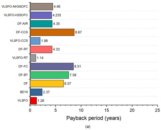
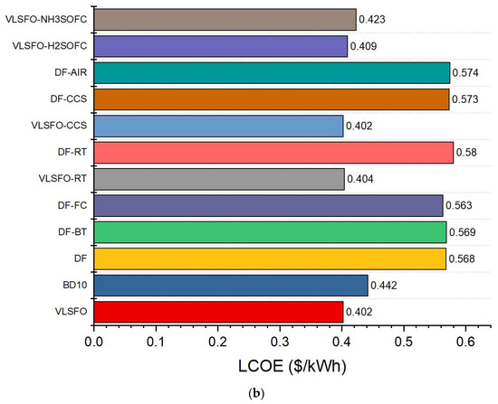
Figure 7.
(a) DPP without carbon tax; (b) LCOE without carbon tax.
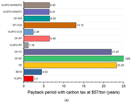
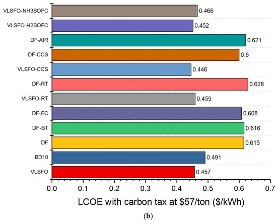
Figure 8.
(a) DPP with carbon tax; (b) LCOE with carbon tax.
Highlighting the importance of the payback period on the psyche of a ship owner, Stott [96] performed a market-based study in which he highlighted that only 20% of deep-sea vessel owners utilized a ship for the entirety of its lifetime, whereas a majority of shipowners preferred to sell a vessel ten years after purchase. Subsequently, the market for second-hand purchases of ships is on the rise, with the payback period deeply influencing the decision to invest in a deep-sea vessel. Of course, freight profits heavily play a part in determining the profit margins [97]. However, making less carbon-intensive deep-sea vessels which exhibit a payback period solely based on the powertrain, less than the intended investment maturity period in the shipowners’ mind, would attract a higher investor confidence. Comparing Figure 7 and Figure 8, the carbon tax levy condemns several scenario cases as unfavourable (>10 years). However, it is interesting to note how the retrofitting of Flettner rotors decreases the payback period of the DF case by 78%, even with the carbon tax.
While the fuel price plays a pivotal role in determining the payback period, equally important is the unit price of electricity in determining cash inflow (revenue). According to [57,98,99], electricity prices are dependent on wholesale fuel prices, which are subject to change based on demand and geopolitics. While the claim that electricity prices are fuel cost-dependent seems to be true, the increment does not seem to be relative, as the price of LNG increases almost 100% from 2021 to 2022, yet the electricity price increase is only 10% (Figure 3). The payback period calculations are highly sensitive to the instantaneous fuel and electricity prices because while the increase in electricity price may be small, the annual energy generated by the vessel’s engines is much higher than the annual fuel consumption (for reference, the main engine for the VLSFO case produces 44.4 GWh of energy annually, while consuming 7.3 million kg of fuel). Hence, a system of calculations may need to be performed annually since a dynamic system of calculations may be very complex, with fuel prices changing daily. It is currently unknown as to how the carbon tax may be implemented, whether regulated or future market-based. If future market-based, the payback period calculations would need to include the instantaneous carbon tax price, along with the fuel and electricity prices.
3.4. Sensitivity Analysis
Keeping in mind the concluding remarks of Section 3.3, it seemed logical to perform a sensitivity analysis to determine the validity of the methodology and how rapid changes in prices would affect ship owners. Fuel and energy prices are at a historical peak right now, showing high volatility [80]; hence, an electricity and fuel price sensitivity analysis was carried out. We decided to perform the sensitivity analysis separately, keeping the fuel price constant for the electricity price analysis and vice versa. A summary of the variable parameters is shown in Table 5. The results achieved were expected, as an increase in electricity price would increase revenue, reducing the payback period, while an increase in fuel price increases the OPEX, effectively reducing the revenue stream, which negatively impacts the payback period. Notably, from Figure 9b, there seems to be a “break-out” price for fuel. If the price of fuel increases above that break-out threshold, the annual revenue generation would be less than the OPEX, essentially turning the vessel into a non-profitable endeavour.

Table 5.
Sensitivity analysis parameters. To view the numerical value of the constant, refer to Section 2.4.
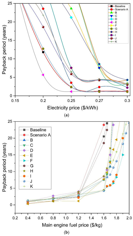
Figure 9.
Effect on DPP of (a) electricity price; (b) fuel price.
With the introduction of a carbon tax, the economic liability would increase, leading to a decrease in revenue. Thus, there would be a “break-out” cost of the carbon tax as well, and the regulating authorities would need to be careful with the implementation of the carbon tax, keeping it just high enough to incur a sizeable financial penalty but not high enough to make deep-sea shipping an unlucrative venture. Figure 10 shows that if a carbon of $90/ton were to be introduced today, only a handful of scenario cases would be economically viable. In this regard, renewable energy technologies (such as Flettner rotor) would show the highest performance since they would provide dual economic benefits: fuel and carbon tax savings.
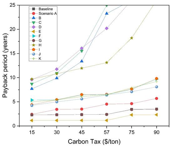
Figure 10.
Effect of carbon tax price change on DPP.
4. Conclusions
This paper investigated the environmental and economic impact of the implementation of decarbonization technologies via a detailed scenario study in the deep-sea shipping industry. We show that the applicability of decarbonization technologies can be considered a high-yield investment rather than a regulated penalty by considering fuel savings and carbon tax levy. The baseline scenario case of an Aframax tanker using VLSFO as fuel is scrutinized, while subsequent scenario cases utilize different decarbonization technologies, including alternative fuels, alternative energy, energy saving, and carbon capture and storage technologies. The common variable between each scenario case is that engine modification is not considered, as the case ship is fitted with an LNG-ready dual fuel engine.
Based on the IMO 2050 GHG emissions reduction policy, an action timeline was generated to provide an overview of how the decarbonization technologies would meet the targets, shown in Figure 11. This action timeline has been developed keeping in mind the needs of existing ships, where complete engine replacement to accommodate other fuels may prove to be very costly. The compliance can be extended by retrofitting different technologies to work in tandem. By 2050, the price of green hydrogen and ammonia is expected to be competitive with traditional fuels [93], and a complete transition to alternative fuels would become a real possibility.
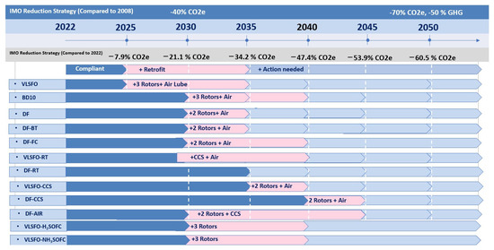
Figure 11.
Action timeline for ship owners to comply with IMO regulations.
With the inevitable advent of alternative fuels, the fuel volumetric energy densities should be of the highest concern since that would be a driving factor in determining the initial fuel storage CAPEX. Our results indicate that several technologies, especially the Flettner rotors, will help in the reduction in fuel consumption of a vessel. The Flettner rotors reduce fuel consumption by up to 11%. While the fuel cells increase the cost of fuel storage capacity, their emissions reduction potential cannot be ignored. Partial electrification might be a viable solution for decarbonization, especially considering that renewable wind electricity is now cheaper than fossil fuel electricity [100]. However, technical constraints from battery storage requirements would need to be addressed in this regard. The environmental study results stem primarily from fuel savings. In the case of alternative fuels, the relative potency of different pollutants needs to be considered individually. This is especially true for LNG, which has high methane emissions and thus counteracts the reduced CO2 emissions. One of the most important indications from this study is that the best-performing alternative energy technology, the Flettner rotor, provides the same environmental benefits to the baseline scenario as switching to LNG as the alternative fuel. Switching to LNG reduces GHG emissions by up to 9.2%, whereas retrofitting Flettner rotors to the baseline scenario reduces GHG emissions by up to 10.3%. This is an important revelation, as LNG is the most carbon-intensive alternative fuel, implying that alternative fuels will always have a higher decarbonization potential. The CAPEX and OPEX, dominated by fuel cost, are important factors when considering the economic implications of decarbonization technologies. The inclusion of the carbon tax makes alternative energy technologies highly desirable since they provide fuel and carbon tax savings. The economic analysis is highly sensitive to the fuel and electricity prices (for revenue generation). Fuel cells currently exhibit the highest capital cost: up to three times higher than the baseline scenario. Innovative business models and financial incentives are needed to address these high capital costs. The environmental impact of deep-sea shipping is of a much higher magnitude than the propulsion costs. Hence, financial incentives to build bunkering infrastructure and lower capital costs would accelerate the move towards carbon-neutral deep-sea shipping.
Author Contributions
Conceptualization, S.F., D.W. and K.D.; Data curation, G.D.K., Z.Y., K.A. and P.D.; Formal analysis, S.F. and M.L.; Funding acquisition, D.W.; Methodology, S.F., M.L., D.W. and K.D.; Resources, G.D.K., Z.Y., K.A. and P.D.; Software, S.F., M.L. and D.W.; Supervision, D.W.; Validation, S.F. and M.L.; Visualization, D.W.; Writing—original draft, S.F. and D.W.; Writing—review and editing, S.F., D.W., G.D.K., K.A. and K.D. All authors have read and agreed to the published version of the manuscript.
Funding
The authors are thankful for the financial support from the EPSRC (the Engineering and Physical Sciences Research Council) of the United Kingdom via the research project (EP/S00193X/2, EP/W016656/1, and EP/Y024605/1).
Data Availability Statement
The data presented in this study are available on request from the corresponding author. The data are not publicly available due to privacy concerns from ship owners.
Conflicts of Interest
Authors Georgios D. Kouris, Zacharias Yerasimou, Pavlos Diamantis and Kostas Andrianos was employed by the Alpha Marine Consulting PC. The remaining authors declare that the research was conducted in the absence of any commercial or financial relationships that could be construed as a potential conflict of interest.
Abbreviations
| BD-10 | 10% Biofuel and Diesel blend |
| CCS | Carbon Capture and Storage |
| CII | Carbon Intensity Indicator |
| CO2 | Carbon dioxide |
| CAPEX | Capital Expenditure |
| DF | Dual Fuel |
| DF-AIR | Dual Fuel and Air Lubrication |
| DF-BT | Dual Fuel Battery |
| DF-CCS | Dual Fuel and CCS |
| DF-FC | Dual Fuel and Fuel Cell |
| DF-RT | Dual Fuel and Rotor |
| DPP | Discounted Payback Period |
| EEDI | Energy Efficiency Design Index |
| GHG | Green House Gas |
| GWP | Global Warming Potential |
| HFO | Heavy Fuel Oil |
| ICE | Internal Combustion Engine |
| IMO | International Maritime Organization |
| LCOE | Levelized Cost of Electricity |
| LCV | Lower Calorific Value |
| LHV | Lower Heating Value |
| LNG | Liquefied Natural Gas |
| NOx | Nitrogen oxides |
| PM | Particulate Matter |
| OPEX | Operational Expenditure |
| O&M | Maintenance cost |
| SFOC | Specific Fuel Oil Consumption |
| SOx | Sulphur oxides |
| VLSFO | Very Low Sulphur Fuel Oil |
| VLSFO-CCS | Very Low Sulphur Fuel Oil and CCS |
| VLSFO-H2SOFC | Very Low Sulphur Fuel Oil and Hydrogen Solid Oxide Fuel Cell |
| VLSFO-NH3SOFC | Very Low Sulphur Fuel Oil and Ammonia Solid Oxide Fuel Cell |
| VLSFO-RT | Very Low Sulphur Fuel Oil and Rotor |
| WASP | Wind Assisted Ship Propulsion |
| WTW | Well to Wake |
| Symbols | |
| Fuel cell efficiency | |
| Cinv | Investment cost, $ |
| Cinv, a | Annual investment cost, $ |
| Crep | Replacement cost, $ |
| Crep, a | Annualized replacement cost, $ |
| CO&M, a | Annualized operation and maintenance cost, $ |
| CO&M, Engines | Annualized engine operation and maintenance cost, $ |
| CO&M, Fuel cost | Annualized fuel cost, $ |
| CO&M, decarbonization | Annualized decarbonization technology operation and maintenance cost, $ |
| CCarbon tax, a | Annualized carbon tax, $ |
| Cap | Capital cost, $ |
| CIIbaseline/DF | Baseline or dual fuel carbon intensity metric, g/t*nm |
| dt | Voyage time, hours |
| EEDIbaseline/DF | Baseline or dual fuel energy efficiency design index, g/t*nm |
| FEEDI | Energy efficiency design index factor |
| F | GHG factor |
| FAECO2e20 | Auxiliary engine GHG factor 20 years |
| FAECO2e100 | Auxiliary engine GHG factor 100 years |
| FMECO2e20 | Main engine GHG factor 20 years |
| FMECO2e100 | Main engine GHG factor 100 years |
| GHGCO2e20 | GHG emissions 20 years |
| GHGCO2e20 | GHG emissions 100 years |
| i | Annual interest rate |
| M(fuel) | Annual fuel consumption, kg |
| M(fuel)AE | Annual fuel consumption auxiliary engine, kg |
| M(fuel)ME | Annual fuel consumption auxiliary engine, kg |
| M(fuel)PEMFC,SOFC | Annual fuel consumption for fuel cells, kg |
| NAIj | Net annual income (j is the year in the system lifetime), $ |
| PAE | Auxiliary engine power requirement, W |
| Pbaseline | Baseline power requirement, W |
| PME | Main engine power requirement, W |
| Specific price of electricity, $/kWh | |
| PEj | Annual electricity production, kWh |
| Rtj | Annual revenue, $ |
| SFOCAE | Auxiliary engine specific fuel oil consumption, g/kWh |
| SFOCME | Main engine specific fuel oil consumption, g/kWh |
| t | Year of replacement |
| We | Annual electricity production |
| z | Product lifetime, year |
References
- Balcombe, P.; Brierley, J.; Lewis, C.; Skatvedt, L.; Speirs, J.; Hawkes, A.; Staffell, I. How to decarbonise international shipping: Options for fuels, technologies and policies. Energy Convers. Manag. 2019, 182, 72–88. [Google Scholar] [CrossRef]
- Faber, J.; Hanayama, S.; Zhang, S.; Pereda, P.; Comer, B.; Hauerhof, E.; van der Loeff, W.S.; Smith, T.; Zhang, Y.; Kosaka, H. Reduction of GHG emissions from ships—Fourth IMO GHG study 2020—Final report. IMO MEPC 2020, 75, 15. [Google Scholar]
- IMO. Adoption of the Initial IMO Strategy on Reduction of GHG Emissions from Ships and Existing IMO Activity Related to Reducing GHG Emissions in the Shipping Sector. 2018. Available online: https://unfccc.int/sites/default/files/resource/250_IMO%20submission_Talanoa%20Dialogue_April%202018.pdf (accessed on 11 July 2022).
- Goulielmos, A.M. The Initial 40 Years of the EC Maritime Policy, Part I: 1957–1997: Is EU-27 Maritime Industry “Fit for 55”? Mod. Econ. 2022, 13, 159–185. [Google Scholar] [CrossRef]
- Ampah, J.D.; Liu, X.; Sun, X.; Pan, X.; Xu, L.; Jin, C.; Sun, T.; Geng, Z.; Afrane, S.; Liu, H. Study on characteristics of marine heavy fuel oil and low carbon alcohol blended fuels at different temperatures. Fuel 2022, 310, 122307. [Google Scholar] [CrossRef]
- Jin, C.; Sun, T.; Ampah, J.D.; Liu, X.; Geng, Z.; Afrane, S.; Yusuf, A.A.; Liu, H. Comparative study on synthetic and biological surfactants’ role in phase behavior and fuel properties of marine heavy fuel oil-low carbon alcohol blends under different temperatures. Renew. Energy 2022, 195, 841–852. [Google Scholar] [CrossRef]
- Andersson, C.; Bergström, R.; Johansson, C. Population exposure and mortality due to regional background PM in Europe–Long-term simulations of source region and shipping contributions. Atmos. Environ. 2009, 43, 3614–3620. [Google Scholar] [CrossRef]
- Korberg, A.D.; Brynolf, S.; Grahn, M.; Skov, I.R. Techno-economic assessment of advanced fuels and propulsion systems in future fossil-free ships. Renew. Sustain. Energy Rev. 2021, 142, 110861. [Google Scholar] [CrossRef]
- Bouman, E.A.; Lindstad, E.; Rialland, A.I.; Strømman, A.H. State-of-the-art technologies, measures, and potential for reducing GHG emissions from shipping—A review. Transp. Res. Part D Transp. Environ. 2017, 52, 408–421. [Google Scholar] [CrossRef]
- Bernatik, A.; Senovsky, P.; Pitt, M. LNG as a potential alternative fuel–safety and security of storage facilities. J. Loss Prev. Process Ind. 2011, 24, 19–24. [Google Scholar] [CrossRef]
- Burel, F.; Taccani, R.; Zuliani, N. Improving sustainability of maritime transport through utilization of Liquefied Natural Gas (LNG) for propulsion. Energy 2013, 57, 412–420. [Google Scholar] [CrossRef]
- Elgohary, M.M.; Seddiek, I.S.; Salem, A.M. Overview of alternative fuels with emphasis on the potential of liquefied natural gas as future marine fuel. Proc. Inst. Mech. Eng. Part M J. Eng. Marit. Environ. 2015, 229, 365–375. [Google Scholar] [CrossRef]
- LNGPRIME. DNV Reports New Monthly Record for LNG-Fueled Ship Orders. Available online: https://lngprime.com/europe/dnv-reports-new-monthly-record-for-lng-fueled-ship-orders/50299/ (accessed on 11 June 2022).
- Yoo, B.-Y. Economic assessment of liquefied natural gas (LNG) as a marine fuel for CO2 carriers compared to marine gas oil (MGO). Energy 2017, 121, 772–780. [Google Scholar] [CrossRef]
- Balcombe, P.; Staffell, I.; Kerdan, I.G.; Speirs, J.F.; Brandon, N.P.; Hawkes, A.D. How can LNG-fuelled ships meet decarbonisation targets? An environmental and economic analysis. Energy 2021, 227, 120462. [Google Scholar] [CrossRef]
- Hwang, S.; Jeong, B.; Jung, K.; Kim, M.; Zhou, P. Life cycle assessment of LNG fueled vessel in domestic services. J. Mar. Sci. Eng. 2019, 7, 359. [Google Scholar] [CrossRef]
- Mukherjee, A.; Bruijnincx, P.; Junginger, M. A perspective on biofuels use and CCS for GHG mitigation in the marine sector. Iscience 2020, 23, 101758. [Google Scholar] [CrossRef] [PubMed]
- Stathatou, P.M.; Bergeron, S.; Fee, C.; Jeffrey, P.; Triantafyllou, M.; Gershenfeld, N. Towards decarbonization of shipping: Direct emissions & life cycle impacts from a biofuel trial aboard an ocean-going dry bulk vessel. Sustain. Energy Fuels 2022, 6, 1687–1697. [Google Scholar]
- Ammar, N.R. An environmental and economic analysis of methanol fuel for a cellular container ship. Transp. Res. Part D Transp. Environ. 2019, 69, 66–76. [Google Scholar] [CrossRef]
- Radonja, R.; Bebić, D.; Glujić, D. Methanol and ethanol as alternative fuels for shipping. Promet-Traffic Transp. 2019, 31, 321–327. [Google Scholar] [CrossRef]
- Liu, M.; Li, C.; Koh, E.K.; Ang, Z.; Lam, J.S.L. Is methanol a future marine fuel for shipping? J. Phys. Conf. Ser. 2019, 1357, 012014. [Google Scholar] [CrossRef]
- Svanberg, M.; Ellis, J.; Lundgren, J.; Landälv, I.J.R.; Reviews, S.E. Renewable methanol as a fuel for the shipping industry. Renew. Sustain. Energy Rev. 2018, 94, 1217–1228. [Google Scholar] [CrossRef]
- GOV.UK. Agriculture in the UK Evidence Pack. 2022. Available online: https://assets.publishing.service.gov.uk/government/uploads/system/uploads/attachment_data/file/1106562/AUK_Evidence_Pack_2021_Sept22.pdf (accessed on 11 July 2022).
- Bicer, Y.; Dincer, I. Clean fuel options with hydrogen for sea transportation: A life cycle approach. Int. J. Hydrog. Energy 2018, 43, 1179–1193. [Google Scholar] [CrossRef]
- Wang, Y.; Zhou, X.; Liu, L. Theoretical investigation of the combustion performance of ammonia/hydrogen mixtures on a marine diesel engine. Int. J. Hydrog. Energy 2021, 46, 14805–14812. [Google Scholar] [CrossRef]
- Lhuillier, C.; Brequigny, P.; Contino, F.; Mounaïm-Rousselle, C. Experimental study on ammonia/hydrogen/air combustion in spark ignition engine conditions. Fuel 2020, 269, 117448. [Google Scholar] [CrossRef]
- Frigo, S.; Gentili, R. Analysis of the behaviour of a 4-stroke Si engine fuelled with ammonia and hydrogen. Int. J. Hydrog. Energy 2013, 38, 1607–1615. [Google Scholar] [CrossRef]
- Al-Aboosi, F.Y.; El-Halwagi, M.M.; Moore, M.; Nielsen, R.B. Renewable ammonia as an alternative fuel for the shipping industry. Curr. Opin. Chem. Eng. 2021, 31, 100670. [Google Scholar] [CrossRef]
- EMSA. Potential of Ammonia as Fuel in Shipping. Available online: https://www.emsa.europa.eu/newsroom/latest-news/item/4833-potential-of-ammonia-as-fuel-in-shipping.html (accessed on 14 November 2023).
- Environment, T. Road Map to Decarbonising European Shipping. Available online: https://www.transportenvironment.org/discover/roadmap-decarbonising-european-shipping/ (accessed on 14 November 2023).
- Gholami, A.; Jazayeri, S.A.; Esmaili, Q. A detail performance and CO2 emission analysis of a very large crude carrier propulsion system with the main engine running on dual fuel mode using hydrogen/diesel versus natural gas/diesel and conventional diesel engines. Process Saf. Environ. Prot. 2022, 163, 621–635. [Google Scholar] [CrossRef]
- Madsen, R.; Klebanoff, L.; Caughlan, S.; Pratt, J.; Leach, T.; Appelgate, T., Jr.; Kelety, S.; Wintervoll, H.-C.; Haugom, G.; Teo, A. Feasibility of the Zero-V: A zero-emissions hydrogen fuel-cell coastal research vessel. Int. J. Hydrog. Energy 2020, 45, 25328–25343. [Google Scholar] [CrossRef]
- Ghenai, C.; Bettayeb, M.; Brdjanin, B.; Hamid, A.K. Hybrid solar PV/PEM fuel Cell/Diesel Generator power system for cruise ship: A case study in Stockholm, Sweden. Case Stud. Therm. Eng. 2019, 14, 100497. [Google Scholar] [CrossRef]
- Han, J.; Charpentier, J.-F.; Tang, T. An energy management system of a fuel cell/battery hybrid boat. Energies 2014, 7, 2799–2820. [Google Scholar] [CrossRef]
- Wu, S.; Miao, B.; Chan, S.H. Feasibility assessment of a container ship applying ammonia cracker-integrated solid oxide fuel cell technology. Int. J. Hydrog. Energy 2022, 47, 27166–27176. [Google Scholar] [CrossRef]
- Kim, K.; Roh, G.; Kim, W.; Chun, K. A preliminary study on an alternative ship propulsion system fueled by ammonia: Environmental and economic assessments. J. Mar. Sci. Eng. 2020, 8, 183. [Google Scholar] [CrossRef]
- Zincir, B. Environmental and economic evaluation of ammonia as a fuel for short-sea shipping: A case study. Int. J. Hydrog. Energy 2022, 47, 18148–18168. [Google Scholar] [CrossRef]
- Howarth, R.W.; Jacobson, M.Z. How green is blue hydrogen? Energy Sci. Eng. 2021, 9, 1676–1687. [Google Scholar] [CrossRef]
- Yu, M.; Wang, K.; Vredenburg, H. Insights into low-carbon hydrogen production methods: Green, blue and aqua hydrogen. Int. J. Hydrog. Energy 2021, 46, 21261–21273. [Google Scholar] [CrossRef]
- del Pozo, C.A.; Cloete, S. Techno-economic assessment of blue and green ammonia as energy carriers in a low-carbon future. Energy Convers. Manag. 2022, 255, 115312. [Google Scholar] [CrossRef]
- Veldhuis, I.; Richardson, R.; Stone, H. Hydrogen fuel in a marine environment. Int. J. Hydrog. Energy 2007, 32, 2553–2566. [Google Scholar] [CrossRef]
- Atilhan, S.; Park, S.; El-Halwagi, M.M.; Atilhan, M.; Moore, M.; Nielsen, R.B. Green hydrogen as an alternative fuel for the shipping industry. Curr. Opin. Chem. Eng. 2021, 31, 100668. [Google Scholar] [CrossRef]
- Ampah, J.D.; Yusuf, A.A.; Afrane, S.; Jin, C.; Liu, H. Reviewing two decades of cleaner alternative marine fuels: Towards IMO’s decarbonization of the maritime transport sector. J. Clean. Prod. 2021, 320, 128871. [Google Scholar] [CrossRef]
- Mallouppas, G.; Yfantis, E.A. Decarbonization in shipping industry: A review of research, technology development, and innovation proposals. J. Mar. Sci. Eng. 2021, 9, 415. [Google Scholar] [CrossRef]
- Seddiek, I.S.; Ammar, N.R. Harnessing wind energy on merchant ships: Case study Flettner rotors onboard bulk carriers. Environ. Sci. Pollut. Res. 2021, 28, 32695–32707. [Google Scholar] [CrossRef]
- Lu, R.; Ringsberg, J.W. Ship energy performance study of three wind-assisted ship propulsion technologies including a parametric study of the Flettner rotor technology. Ships Offshore Struct. 2020, 15, 249–258. [Google Scholar] [CrossRef]
- Traut, M.; Gilbert, P.; Walsh, C.; Bows, A.; Filippone, A.; Stansby, P.; Wood, R. Propulsive power contribution of a kite and a Flettner rotor on selected shipping routes. Appl. Energy 2014, 113, 362–372. [Google Scholar] [CrossRef]
- Zhang, P.; Lozano, J.; Wang, Y. Using Flettner Rotors and Parafoil as alternative propulsion systems for bulk carriers. J. Clean. Prod. 2021, 317, 128418. [Google Scholar] [CrossRef]
- Tillig, F.; Mao, W.; Ringsberg, J. Systems Modelling for Energy-Efficient Shipping; Chalmers University of Technology: Gothenburg, Sweden, 2015. [Google Scholar]
- Wang, H.; Lutsey, N. Long-term potential for increased shipping efficiency through the adoption of industry-leading practices. Int. Counc. Clean Transp. 2013, 65. Available online: https://d1wqtxts1xzle7.cloudfront.net/89020428/ICCT_ShipEfficiency_20130723-libre.pdf?1658862635=&response-content-disposition=inline%3B+filename%3DLong_term_potential_for_increased_shippi.pdf&Expires=1700154448&Signature=FZJZMhkrmuiRpQmJdQ8qwHWkBZOVEzdah7VVS2izS2B1RxgvGhCiGrbrbNtcxUczoqhfDneXQUI1wFexlhrJOwKyONysrSbfduSOTlgytrPs~PjUXKxmnX7E8fW~~KjIg49uUvZogddyKP97m3YXpvoIxN6JIju5B2eOL7D67Y6P7wI~3WHdg12d0HeSGwjE5cw5~2YjcSB2WZ7Oc4b8myehmVzTDkwT5WAAACogztsveTdTHwUZ07fu-jDWGXb3Ris2nj6GSFtgUiMfS5nZAGZ3hoN524yustzygeckskHkWBkDQz3ZjUIZEbgHDlHcJT1ertjr1N8w~WOpqFk~VA__&Key-Pair-Id=APKAJLOHF5GGSLRBV4ZA (accessed on 14 November 2023).
- Miola, A.; Marra, M.; Ciuffo, B. Designing a climate change policy for the international maritime transport sector: Market-based measures and technological options for global and regional policy actions. Energy Policy 2011, 39, 5490–5498. [Google Scholar] [CrossRef]
- Liu, X.; Zhao, W.; Wan, D. Multi-fidelity Co-Kriging surrogate model for ship hull form optimization. Ocean Eng. 2022, 243, 110239. [Google Scholar] [CrossRef]
- Andersson, J.; Oliveira, D.R.; Yeginbayeva, I.; Leer-Andersen, M.; Bensow, R.E. Review and comparison of methods to model ship hull roughness. Appl. Ocean Res. 2020, 99, 102119. [Google Scholar] [CrossRef]
- Silberschmidt, N.; Tasker, D.; Pappas, T.; Johannesson, J. Silverstream system-air lubrication performance verification and design development. In Proceedings of the Conference of Shipping in Changing Climate, Newcastle, UK, 10–11 November 2016; pp. 10–11. [Google Scholar]
- GOV.UK. Energy Trends and Prices Statistical Release: 24 February 2022. 2022. Available online: https://www.gov.uk/government/statistics/energy-trends-and-prices-statistical-release-24-february-2022 (accessed on 14 November 2023).
- Wang, H.; Boulougouris, E.; Theotokatos, G.; Zhou, P.; Priftis, A.; Shi, G. Life cycle analysis and cost assessment of a battery powered ferry. Ocean Eng. 2021, 241, 110029. [Google Scholar] [CrossRef]
- Kersey, J.; Popovich, N.D.; Phadke, A.A. Rapid battery cost declines accelerate the prospects of all-electric interregional container shipping. Nat. Energy 2022, 7, 664–674. [Google Scholar] [CrossRef]
- Minnehan, J.J.; Pratt, J.W. Practical Application Limits of Fuel Cells and Batteries for Zero Emission Vessels; Sandia National Laboratories (SNL-NM): Albuquerque, NM, USA, 2017. [Google Scholar]
- Luo, X.; Wang, M. Study of solvent-based carbon capture for cargo ships through process modelling and simulation. Appl. Energy 2017, 195, 402–413. [Google Scholar] [CrossRef]
- Feenstra, M.; Monteiro, J.; van den Akker, J.T.; Abu-Zahra, M.R.; Gilling, E.; Goetheer, E. Ship-based carbon capture onboard of diesel or LNG-fuelled ships. Int. J. Greenh. Gas Control 2019, 85, 1–10. [Google Scholar] [CrossRef]
- Ros, J.A.; Skylogianni, E.; Doedée, V.; van den Akker, J.T.; Vredeveldt, A.W.; Linders, M.J.; Goetheer, E.L.; Monteiro, J.G.M. Advancements in ship-based carbon capture technology on board of LNG-fuelled ships. Int. J. Greenh. Gas Control 2022, 114, 103575. [Google Scholar] [CrossRef]
- Wartsila. Wärtsilä Advances Carbon Capture and Storage in Maritime as Part of LINCCS Consortium. Available online: https://www.wartsila.com/media/news/08-09-2021-wartsila-advances-carbon-capture-and-storage-in-maritime-as-part-of-linccs-consortium-2972116 (accessed on 1 June 2022).
- Freightify. Top 5 Busiest Global Major Shipping Routes 2022. Available online: https://www.freightify.com/blog/busiest-global-trade-shipping-routes-2021 (accessed on 11 June 2022).
- Ports. Sea Routes and Distances. Available online: http://ports.com/sea-route (accessed on 11 June 2022).
- Maritime, A. Aframax Tanker Drawings and Engine Data; Alpha Marine Consulting: Pireas, Greece, 2022. [Google Scholar]
- Zis, T.P.; Psaraftis, H.N.; Tillig, F.; Ringsberg, J.W. Decarbonizing maritime transport: A Ro-Pax case study. Res. Transp. Bus. Manag. 2020, 37, 100565. [Google Scholar] [CrossRef]
- Wang, D.; Zhang, H.; Qian, Y.; Deng, K. Experimental energy and exergy analysis of turbocharged marine low-speed engine with high pressure exhaust gas recirculation. Fuel 2022, 323, 124360. [Google Scholar] [CrossRef]
- Ahmad, F.; Khalid, M.; Panigrahi, B.K. Development in energy storage system for electric transportation: A comprehensive review. J. Energy Storage 2021, 43, 103153. [Google Scholar] [CrossRef]
- Balsamo, F.; Capasso, C.; Lauria, D.; Veneri, O. Optimal design and energy management of hybrid storage systems for marine propulsion applications. Appl. Energy 2020, 278, 115629. [Google Scholar] [CrossRef]
- Deloitte China. Fueling the Future of Mobility. Hydrog. Fuel Cell Solut. Transp. 2020, 1. Available online: https://www2.deloitte.com/content/dam/Deloitte/uk/Documents/energy-resources/deloitte-uk-energy-resources-investing-in-hydrogen.pdf (accessed on 11 June 2022).
- Norsepower. Norsepower|Rotor Sails|Wind Propulsion. Available online: https://www.norsepower.com/ (accessed on 11 June 2022).
- Ma, H.; Steernberg, K.; Riera-Palou, X.; Tait, N. Well-to-wake energy and greenhouse gas analysis of SOX abatement options for the marine industry. Transp. Res. Part D Transp. Environ. 2012, 17, 301–308. [Google Scholar] [CrossRef]
- Comer, B.; Osipova, L. Accounting for Well-to-Wake Carbon Dioxide Equivalent Emissions in Maritime Transportation Climate Policies; The International Council on Clean Transportation (ICCT): Washington, DC, USA, 2021. [Google Scholar]
- Attah, E.E.; Bucknall, R. An analysis of the energy efficiency of LNG ships powering options using the EEDI. Ocean Eng. 2015, 110, 62–74. [Google Scholar] [CrossRef]
- Wang, S.; Psaraftis, H.N.; Qi, J. Paradox of international maritime organization’s carbon intensity indicator. Commun. Transp. Res. 2021, 1, 100005. [Google Scholar] [CrossRef]
- Hon, G.; Wang, H. The Energy Efficiency Design Index (EEDI) for New Ships; The International Council on Clean Transportation (ICCT): Washington, DC, USA, 2011. [Google Scholar]
- Minutillo, M.; Perna, A.; Di Trolio, P.; Di Micco, S.; Jannelli, E. Techno-economics of novel refueling stations based on ammonia-to-hydrogen route and SOFC technology. Int. J. Hydrogen Energy 2021, 46, 10059–10071. [Google Scholar] [CrossRef]
- Duan, G.; Zhang, K. Optimization on hybrid energy vessel routing and energy management for floating marine debris cleanup. Transp. Res. Part C Emerg. Technol. 2022, 138, 103649. [Google Scholar] [CrossRef]
- Zhang, Y.; Zhao, N.; Li, M.; Xu, Z.; Wu, D.; Hillmansen, S.; Tsolakis, A.; Blacktop, K.; Roberts, C. A techno-economic analysis of ammonia-fuelled powertrain systems for rail freight. Transp. Res. Part D Transp. Environ. 2023, 119, 103739. [Google Scholar] [CrossRef]
- Ship&Bunker. World Bunker Prices. Available online: https://shipandbunker.com/prices (accessed on 11 June 2022).
- Metzger, D. Market-based measures and their impact on green shipping technologies. WMU J. Marit. Aff. 2022, 21, 3–23. [Google Scholar] [CrossRef]
- Neste. Available online: https://www.neste.com/investors/market-data (accessed on 11 June 2022).
- Chu, K.H.; Lim, J.; Mang, J.S.; Hwang, M.-H. Evaluation of strategic directions for supply and demand of green hydrogen in South Korea. Int. J. Hydrog. Energy 2021, 47, 1409–1424. [Google Scholar] [CrossRef]
- Global, S.P. Interactive: Platts Ammonia Price Chart. Available online: https://www.spglobal.com/commodityinsights/en/market-insights/latest-news/energy-transition/051023-interactive-ammonia-price-chart-natural-gas-feedstock-europe-usgc-black-sea (accessed on 11 July 2023).
- White, J. Japan’s carbon tax proposal for shipping marks a global shift. Int. Tax Rev. 2022. Available online: https://www.proquest.com/scholarly-journals/japan-s-carbon-tax-proposal-shipping-marks-global/docview/2675440381/se-2?accountid=8630 (accessed on 11 June 2022).
- Puertodemelilla. Régimen de Las Tarifas Portuarias Por Prestación de Servicios Comerciales en Puerto de Melilla. Available online: www.puertodemelilla.es (accessed on 11 June 2022).
- AFDC. Alternative Fuel Price Report. 2022. Available online: https://afdc.energy.gov/ (accessed on 11 July 2022).
- Brynolf, S.; Fridell, E.; Andersson, K. Environmental assessment of marine fuels: Liquefied natural gas, liquefied biogas, methanol and bio-methanol. J. Clean. Prod. 2014, 74, 86–95. [Google Scholar] [CrossRef]
- Jeong, B.; Jang, H.; Lee, W.; Park, C.; Ha, S.; Cho, N.-K. Is electric battery propulsion for ships truly the lifecycle energy solution for marine environmental protection as a whole? J. Clean. Prod. 2022, 355, 131756. [Google Scholar] [CrossRef]
- Lindstad, E.; Bø, T.I. Potential power setups, fuels and hull designs capable of satisfying future EEDI requirements. Transp. Res. Part D Transp. Environ. 2018, 63, 276–290. [Google Scholar] [CrossRef]
- Perčić, M.; Vladimir, N.; Fan, A. Life-cycle cost assessment of alternative marine fuels to reduce the carbon footprint in short-sea shipping: A case study of Croatia. Appl. Energy 2020, 279, 115848. [Google Scholar] [CrossRef]
- NREL. Utility-Scale Battery Storage|Electricity|2021|ATB|NREL. Available online: https://atb.nrel.gov/electricity/2021/utility-scale_battery_storage (accessed on 11 June 2022).
- Delloite. Fueling the Future of Mobility Hydrogen and Fuel Cell Solutions for Transportation (Ballard). 2021. Available online: https://www2.deloitte.com/content/dam/Deloitte/cn/Documents/finance/deloitte-cn-fueling-the-future-of-mobility-en-200101.pdf (accessed on 11 July 2022).
- Ahluwalia, R.; Roh, H.-S.; Peng, J.-K.; Papadias, D.; Baird, A.; Hecht, E.; Ehrhart, B.; Muna, A.; Ronevich, J.; Houchins, C. Liquid hydrogen storage system for heavy duty trucks: Configuration, performance, cost, and safety. Int. J. Hydrog. Energy 2023, 48, 13308–13323. [Google Scholar] [CrossRef]
- Ammermann, H.; Hoff, P.; Atanasiu, M.; Tisler, O.; Kaufmann, M. Advancing Europe’s Energy Systems-Stationary Fuel Cells in Distributed Generation. 2015. Available online: https://www.h2knowledgecentre.com/content/researchpaper1118 (accessed on 11 July 2023).
- Stott, P. A retrospective review of the average period of ship ownership with implications for the potential payback period for retrofitted equipment. Proc. Inst. Mech. Eng. Part M J. Eng. Marit. Environ. 2014, 228, 249–261. [Google Scholar] [CrossRef]
- Adachi, M.; Kosaka, H.; Fukuda, T.; Ohashi, S.; Harumi, K. Economic analysis of trans-ocean LNG-fueled container ship. J. Mar. Sci. Technol. 2014, 19, 470–478. [Google Scholar] [CrossRef]
- Adi, T.W. Influence of fuel price, electricity price, fuel consumption on operating cost, generation and operating income: A case study on PLN. Int. J. Energy Sect. Manag. 2022, 17, 227–250. [Google Scholar] [CrossRef]
- Bhattacharyya, S.C. Fossil-fuel dependence and vulnerability of electricity generation: Case of selected European countries. Energy Policy 2009, 37, 2411–2420. [Google Scholar] [CrossRef]
- Grubb, M. Opinion: Renewables are Cheaper than Ever—So Why Are Household Energy Bills Only Going up? Available online: https://www.ucl.ac.uk/news/2022/jan/opinion-renewables-are-cheaper-ever-so-why-are-household-energy-bills-only-going (accessed on 11 July 2022).
Disclaimer/Publisher’s Note: The statements, opinions and data contained in all publications are solely those of the individual author(s) and contributor(s) and not of MDPI and/or the editor(s). MDPI and/or the editor(s) disclaim responsibility for any injury to people or property resulting from any ideas, methods, instructions or products referred to in the content. |
© 2023 by the authors. Licensee MDPI, Basel, Switzerland. This article is an open access article distributed under the terms and conditions of the Creative Commons Attribution (CC BY) license (https://creativecommons.org/licenses/by/4.0/).