1. Introduction
For PMSM powered by pulse width modulation (PWM), the space and time harmonics of the air gap magnetic field will cause a large eddy current loss in the rotor core and permanent magnet, resulting in rotor heating, permanent magnet demagnetization, and other problems, seriously threatening the safe and reliable operation of the motor. In order to improve the efficiency and operation reliability of the motor, the accurate calculation of the rotor eddy current loss of the PMSM and the research of the method of reducing eddy current loss have been paid more and more attention.
Generally, research on rotor eddy current loss is mainly carried out from the following aspects: the influence of time harmonics caused by inverter and space harmonics caused by fixed rotor structure on rotor eddy current loss in PMSM is analyzed from the principle as well as how to optimize control parameters, optimize stator and rotor structure, and rationally divide permanent magnet to reduce eddy current loss. With the high price of PMs, how to reduce the use of PMs to reduce the cost of motors has also become one of the research hotspots [
1].
Z.Q. Zhu et al. [
2] established a rotor eddy current loss model of a surface-mounted PMSM (SPMSM) including a stator core, air gap, PM, and rotor core in polar coordinates, which is currently recognized as a relatively accurate two-dimensional analytical model. In [
3], the time-step finite element method was used to analyze the loss of the PM and solid mild steel rotor of the concentric-winding fractional slot SPMSM.
In [
4,
5], Yamazaki et al. analyzed the loss of PM after taking carrier harmonics into account in an interior permanent magnet synchronous machine (IPMSM) driven by PWM through a three-dimensional finite element method. The results without considering the carrier harmonics are compared. The research shows that the carrier harmonics of the inverter are the main cause of the loss of PM and the axial length of the block permanent magnet should be less than the skin depth of the eddy current caused by the harmonics to reduce the loss. In [
6], the impact of a rare earth permanent magnet separating on reducing eddy current losses in synchronous motors was analyzed. Most of the losses of PMs are caused by the carrier harmonics of the inverter and the effect of reducing eddy current losses by separating permanent magnets in IPMSMs is smaller than that of SSPMSMs. It is mainly due to the increase in reaction field caused by high-frequency harmonic eddy currents. In [
7], the influence of optimized stator slot shape and rotor bridge on the reduction in PM in weak field areas in an IPMSM was studied. In [
8], the influence of separation on the reduction in PM in concentric-winding PMSM was studied. Different harmonic frequencies and rotor structures (such as surface-mounted type and interior type) were affected differently.
For fractional slot concentric-winding permanent magnet motors, the magnetomotive force harmonics, especially the low-order magnetomotive force harmonics, may cause large eddy current loss of the rotor. Aiming at this problem, Bianchi et al. introduced the influence of magnetomotive force space harmonics on rotor loss in fritter-slot wound permanent magnet motors in [
9,
10,
11], established an analytical model to calculate rotor loss caused by magnetomotive force space harmonics, and discussed the relationship between the pole-slot match and rotor loss. Reference [
12] studied the influence of stator slotting and rotor magnetomotive force harmonics on rotor loss. Experimental results showed that rotor loss under load was caused by rotor magnetomotive force harmonics and that rotor yoke magnetic field saturation would limit rotor loss.
Reference [
13] carried out two kinds of simulation analysis of harmonic current loss of 150 kW IPMSM, that is, the co-simulation of time harmonic current caused by non-sinusoidal voltage excitation generated by space inverter and the simulation of the current source. The difference between the two simulation results is close to 500% and the experimental results are close to the co-simulation results, respectively. Reference [
14] studies the effects of the switching frequency and DC voltage on rotor loss, winding loss, and stator loss of an SPMSM. The research shows that loss of PM is very sensitive to switching frequency. The high DC voltage and low switching frequency will increase rotor loss.
In [
15], the finite element method is adopted to compare and analyze the influence of different stator structures on the performance of high-speed PMSMs and the influence of the slotting effect on stator iron loss, rotor eddy current loss, and cogging torque is discussed. Reference [
16] compared the total iron loss and PM loss of three kinds of rotor structures (type “一” interior, “V” interior, and surface-mounted) in fractional slot PMSMs under constant torque and in weak field areas. The results show that the iron loss of fractional slot PMSM is larger than that of SPMSM but the loss of PM is smaller. The separation of permanent magnets will reduce the loss, which is more obvious in the IPMSM.
In [
17], the time-step transient finite element method is adopted to analyze the permanent magnet loss of SPMSMs. The authors believe that when the permanent magnet is divided into more than two blocks per pole, the permanent magnet loss calculated based on the spatial harmonic method may be incorrect. Since each block has an edge, which means that the temperature distribution of the permanent magnet is uneven, the demagnetization of the permanent magnet should be carefully considered. Reference [
18] describes the influence of the resistivity of the iron ring at the back of the rotor on the eddy current loss of the rotor in a permanent magnet with an outer rotor ring permanent magnet and fractional slot-concentrated winding permanent magnet motor. In [
19], the average loss of the permanent magnet of concentrated winding SPMSMs with different pole-slot matches was studied. The calculation model considered four cases in which the ratio of the harmonic wavelength of the magnetometer to the magnetic pole width of the permanent magnet. In [
20], Guohui Yang et al. focused on the influence of stator slot opening of permanent magnet synchronous motor on the loss of permanent magnets. Reference [
21] proposes a new calculation method for power loss of permanent magnet based on a two-dimensional finite element and fitting method which can achieve the balance of rapidity and accuracy of calculation of permanent magnet loss with sinusoidal input.
In general, the rotor loss in PMSM mainly includes rotor core loss and permanent magnet loss which are caused by the air gap permeability, the space harmonic, and the time harmonic caused by the stator current. For integer slot PMSM, the inverter carrier harmonic is the main cause of PM loss of permanent magnets. Generally, the main measures taken to reduce eddy current loss of permanent magnets are a reasonable partition of permanent magnets and high switching frequency. Relatively speaking, the research on eddy current loss of rotor core is not deep enough. In recent years, the high rotor eddy current loss caused by harmonic magnetomotive force and space harmonic in fractional slot concentrated winding permanent magnet motor is one of the hot research topics of rotor loss.
Therefore, this paper studies the method of reducing the eddy current loss of the rotor core, starting from optimizing the rotor structure of the IPMSM. The research on rotor loss of permanent magnet synchronous motor is extended from the permanent magnet loss to the comprehensive consideration of rotor core loss and permanent magnet loss. References for accurately evaluating the rotor loss model and optimizing rotor selection in the motor design stage are provided.
2. Motor Design Specification
The motor design specification is shown in
Table 1.
The motor employs a 72-slot 12-pol. In order to withstand the challenging heat dissipation conditions, the rotor is equipped with high-temperature samarium cobalt permanent magnets instead of NdFeb permanent magnets.
3. Rotor Core Magnetic Field Analysis
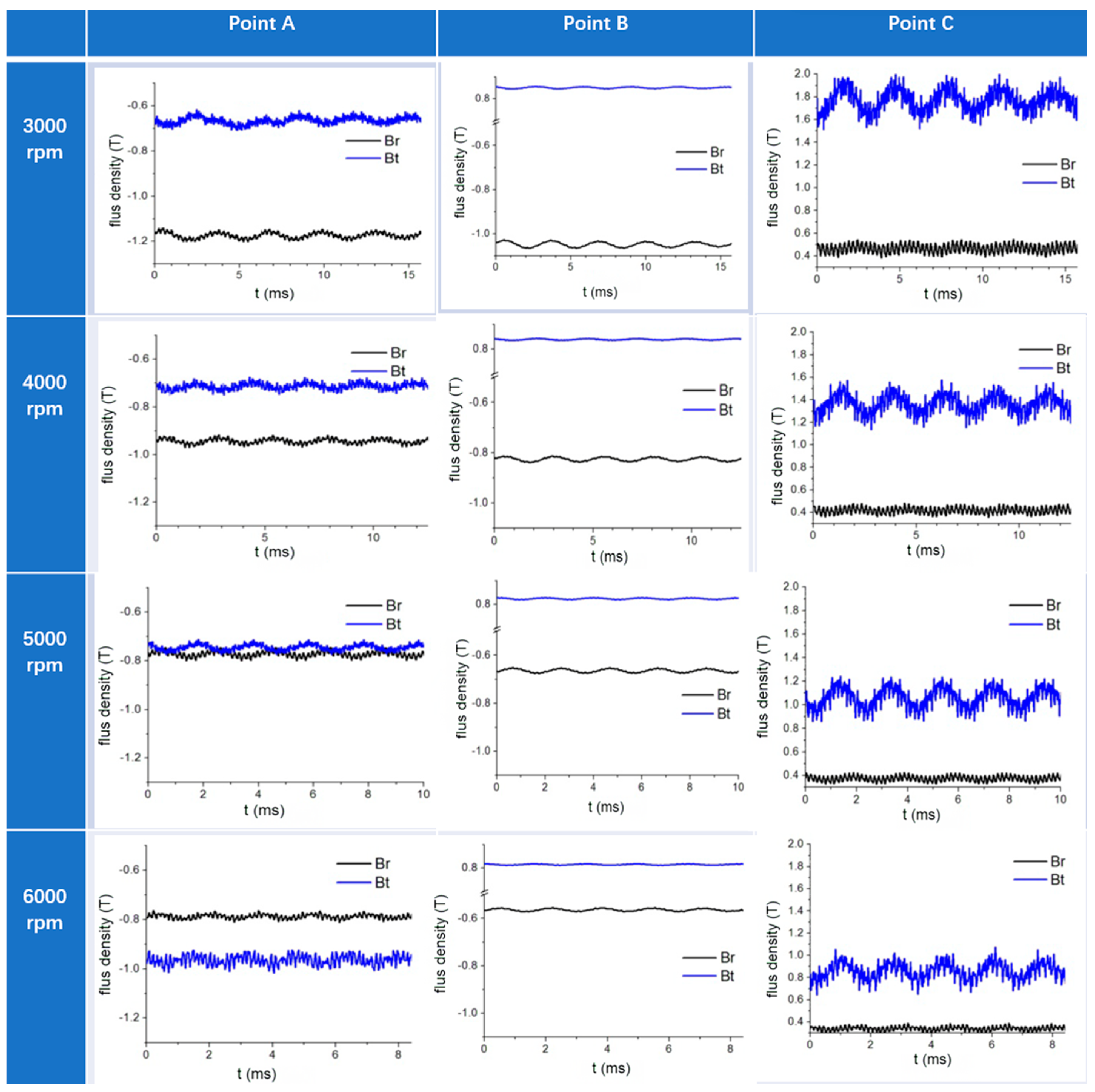
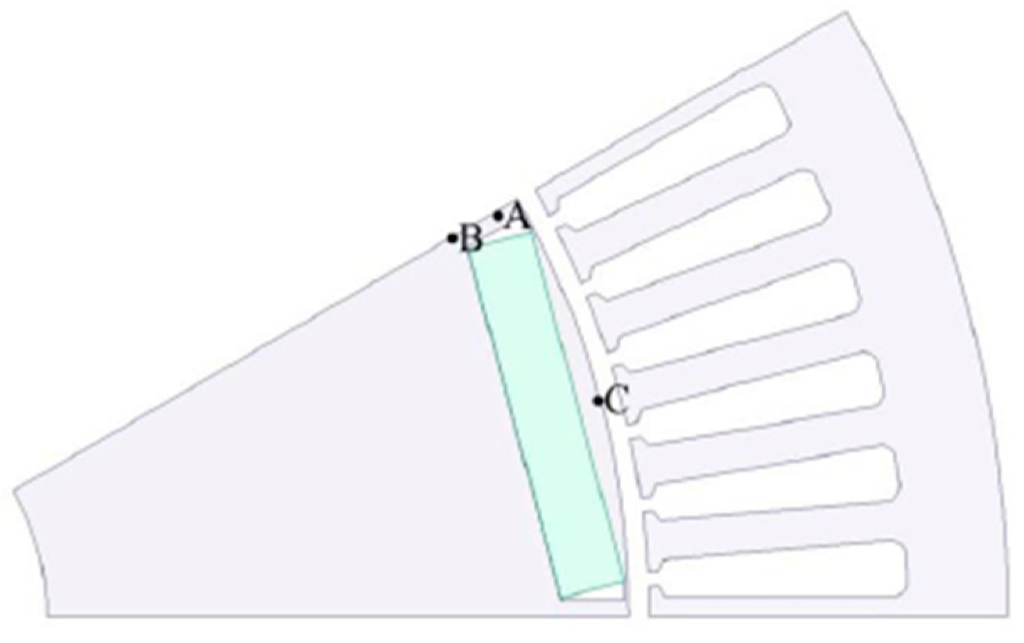
In the weak magnetic area (3000 rpm~6000 rpm), the flux density at three specific positions on the rotor is analyzed over time for rotational speeds of 3000 rpm, 4000 rpm, 5000 rpm, and 6000 rpm. The locations of points A, B, and C are illustrated in
Figure 1 where points A and B reside on the q axis while point C resides on the d axis.
The finite element analysis model is built using Ansoft maxwell 2016. At different speeds, the radial and tangential flux density of three points A, B, and C on the rotor vary with time, as shown in
Figure 2. With the increase in the rotational speed, the weak magnetic current increases, namely the magnetic field in the weak field area, the tangential flux density at point C decreases, the radial flux density at point A and point B increases, and the amplitude of the flux density change gradually decreases. The amplitude of tangential flux density on the q-axis and radial flux density on the d-axis are relatively small.
The higher the upper part of the rotor is affected by the harmonic current magnetic field, the larger the corresponding loss. Due to the large magnetic resistance at the permanent magnet, the rotor core loss is very small and almost negligible. Through the analysis, it can be seen that the loss on the rotor is mainly the eddy current loss of the core and the eddy current loss of the permanent magnet distributed on the outside of the rotor.
On the rotor, harmonic analysis is carried out on the flux density of A, B, and C points. At the same speed, the harmonic frequency of A, B, and C points is the same, which is basically consistent with the harmonic frequency of the A-phase current. This paper only lists the harmonic analysis results of the flux density at point C at each speed, as shown in
Figure 3.
As can be seen from the figure, the influence of higher time harmonics on the flux density of the rotor is very obvious and the main harmonic times at 3000 rpm are 20/27, 47/48, and 68/74. At 4000 rpm, the main harmonic frequency is 16/22, 37/38, and 53/54/60. At 5000 rpm, the main harmonics are 18/19, 30/31 and 42/43/49. At 6000 rpm, they are 15/16, 24/25/26, and 35/41.
4. Rotor Loss Calculation
According to [
22], the total eddy current loss of the permanent magnet can be calculated from the harmonic eddy current density.
where
n is the harmonic order,
σ is the conductivity,
V is the volume of the permanent magnet, and
Jn is the eddy current density of the permanent magnet under the
n-th harmonic.
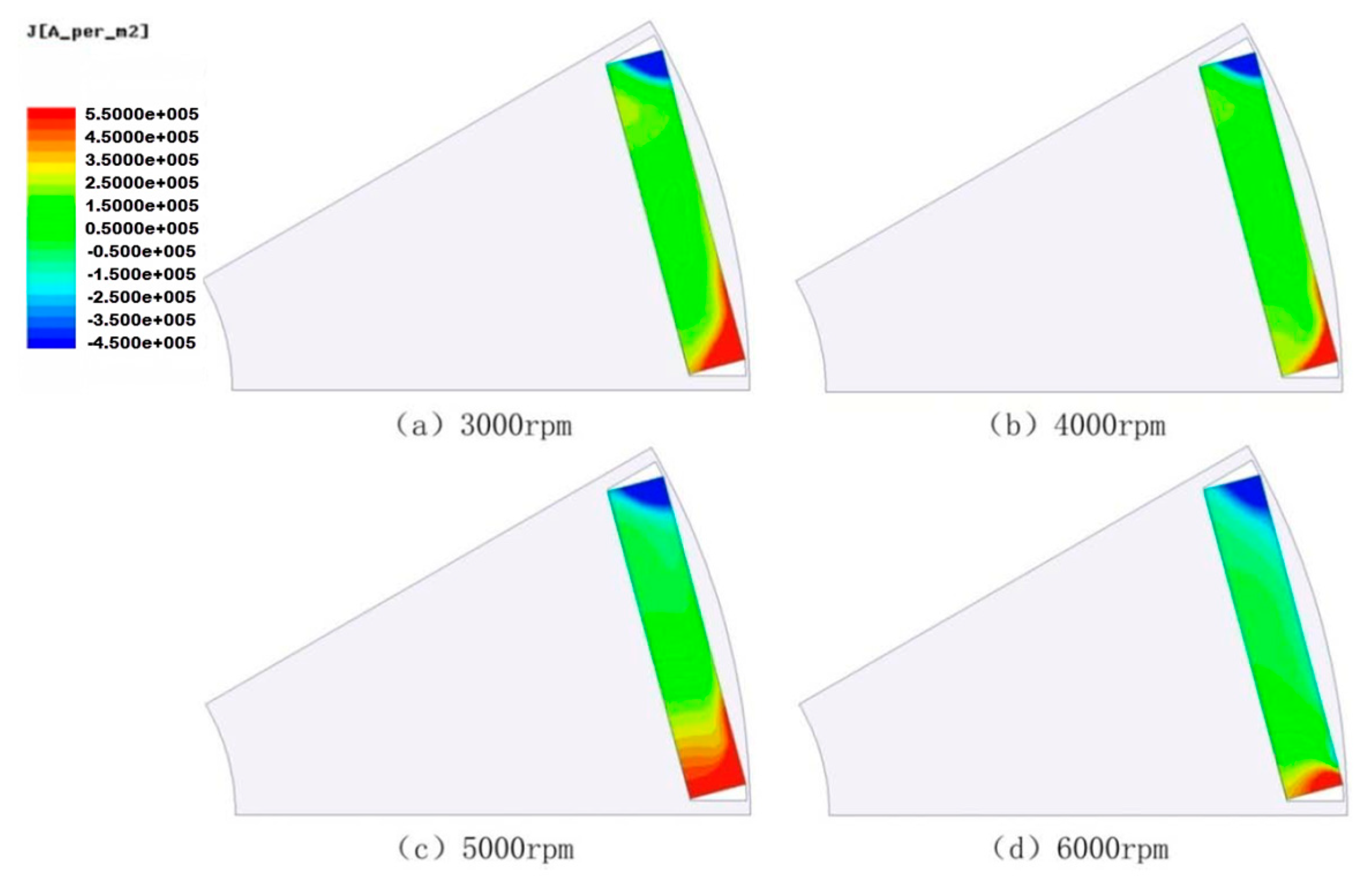
The eddy current density of the permanent magnet at a certain time is shown in
Figure 4.
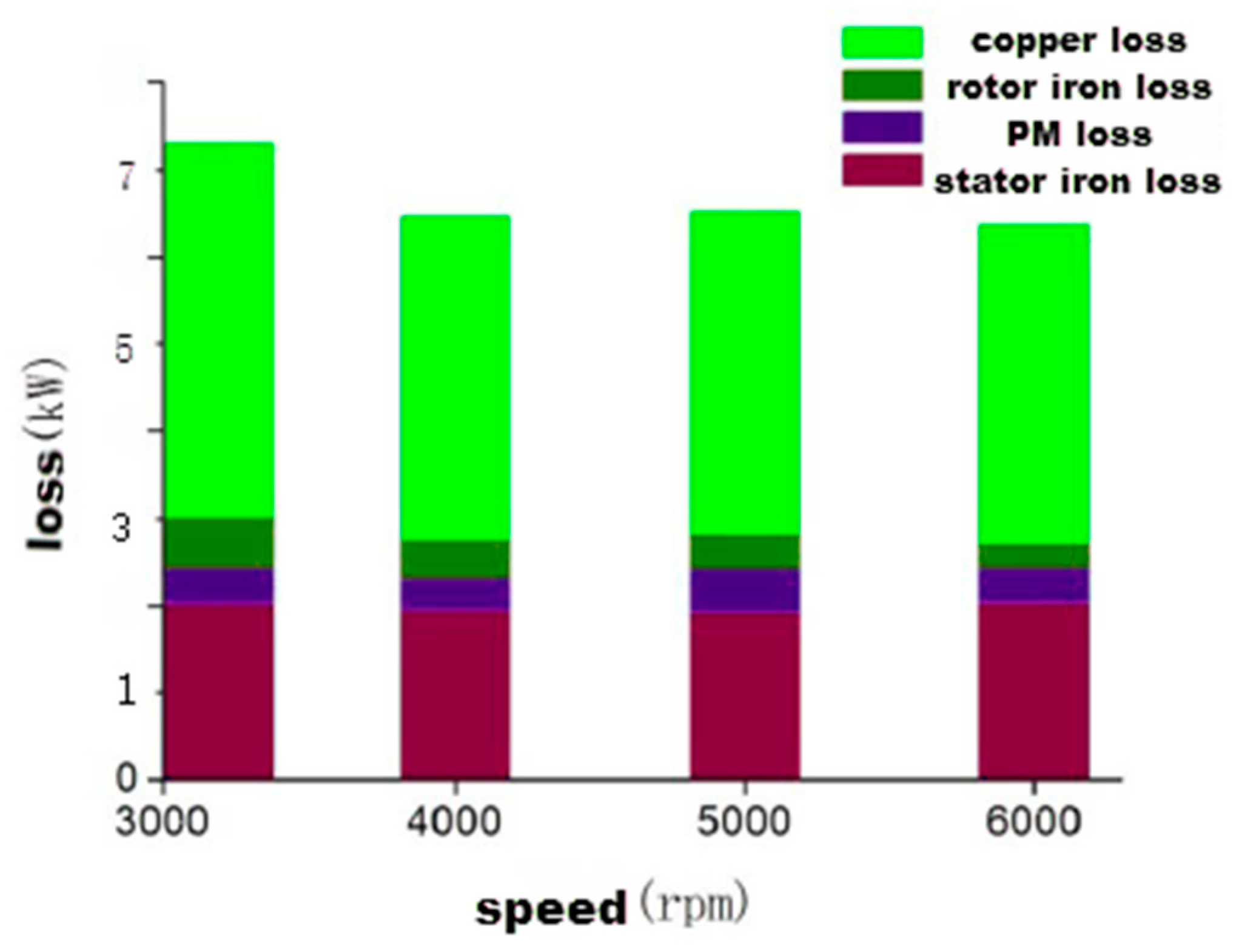
Table 2 and
Figure 5 present the stator core loss, permanent magnet loss, rotor core loss, and copper loss of the motor at different speeds in weak field areas. As the rotational speed increases, there is a corresponding increase in Id while the amplitude of flux density change in the rotor core decreases, leading to a reduction in rotor core loss.
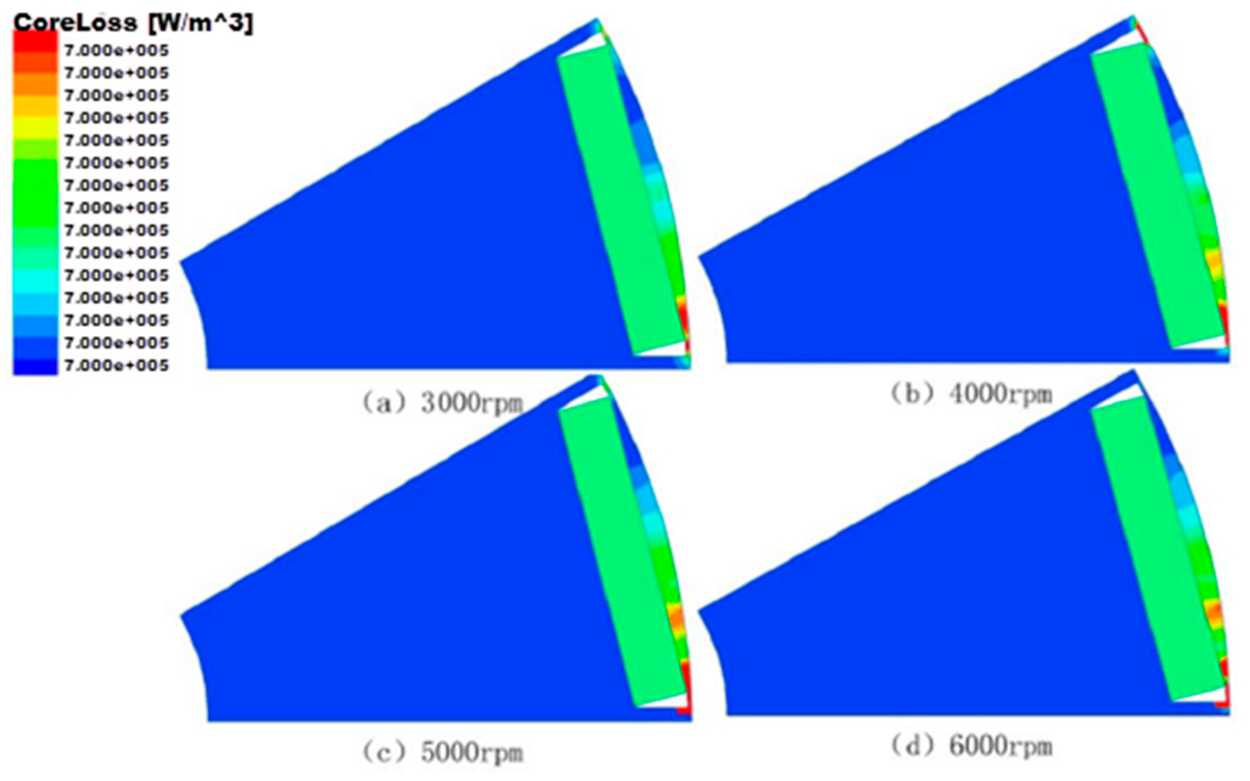
The cloud diagram of rotor core loss at different speeds is shown in
Figure 6. It can be clearly seen from the figure that the rotor core loss of the motor is mainly located on the outside of the rotor, especially at the flux density saturation.
5. Influence of Rotor Structure on Rotor Loss
In order to improve the reliability of the motor, by optimizing the rotor structure, the magnetic field analysis and loss calculation of the IPMSMs with V-type and double V-type IPMSM are carried out to further explore the motor design method to reduce the rotor loss
5.1. Analysis of the Rotor Core Magnetic Field
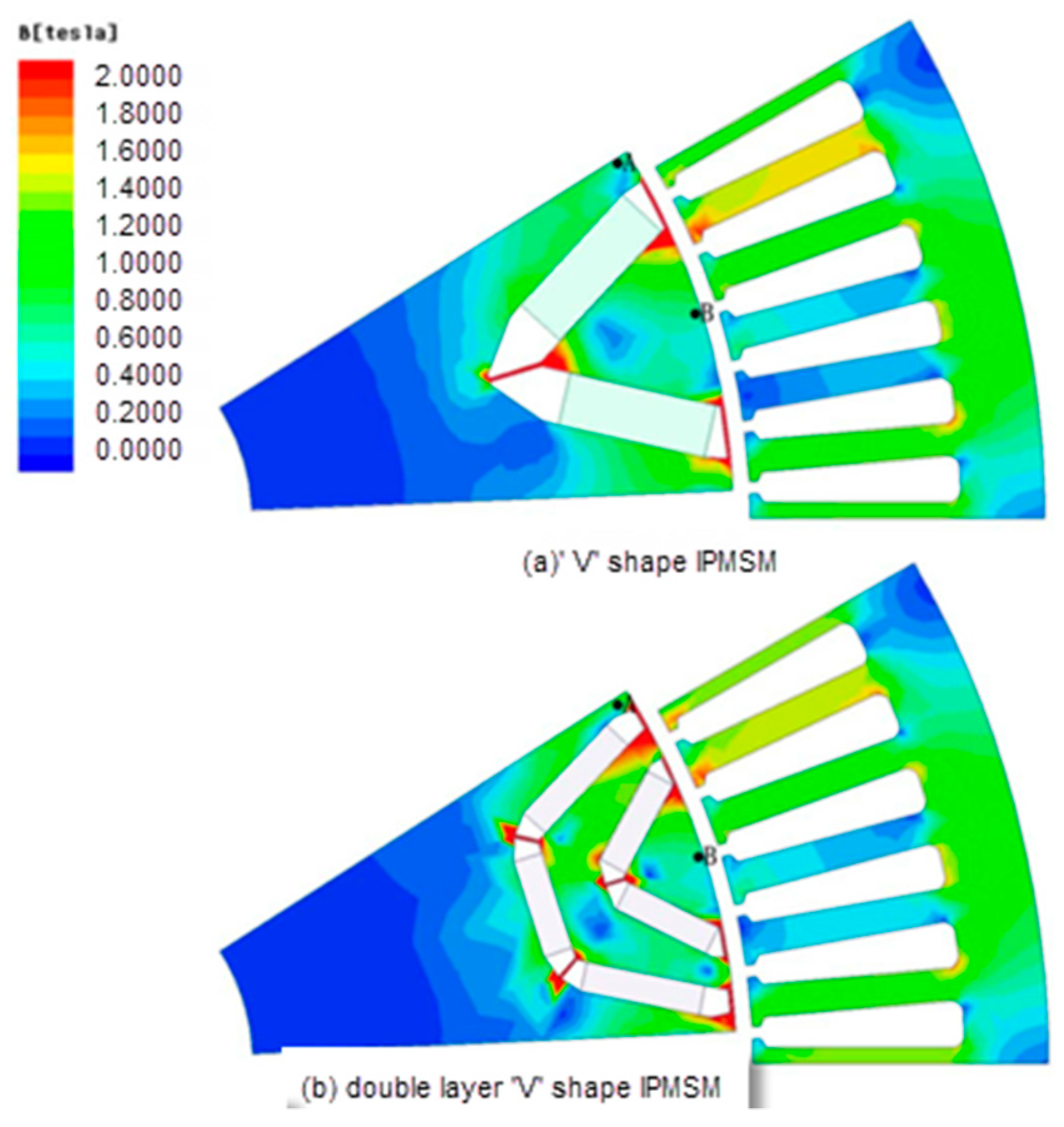
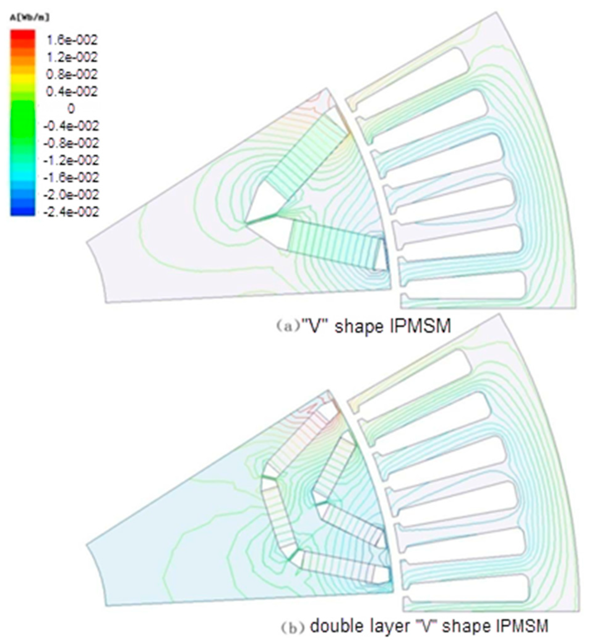
Only the rotor structure was changed for the two motors. The magnetic field distribution of V-type and double V-type IPMSMs under rated load (3000 rpm and 1110 Nm) is shown in
Figure 7.
For PMSM, the magnetic circuit in the rotor of the motor will change without changing the amount of PM and only changing the rotor structure. At the same time, this will also have a certain impact on the stator and rotor loss of the motor. In order to minimize the changing factors, only the influence of the rotor structure change on the rotor loss of the motor is studied and the stator windings of the motor remain unchanged during the optimization process of the V-type and double V-type IPMSMs. In addition, the optimized no-load back potential of the two motors is basically the same (185.6 V and 189.2 V, respectively; at 3000 rpm, the difference is 1.94%) and then the magnetic field distribution and rotor loss of the two rotor structures of V-type and double V-type IPMSM are analyzed.
The flux density cloud diagram under the rated load of the motor is shown in
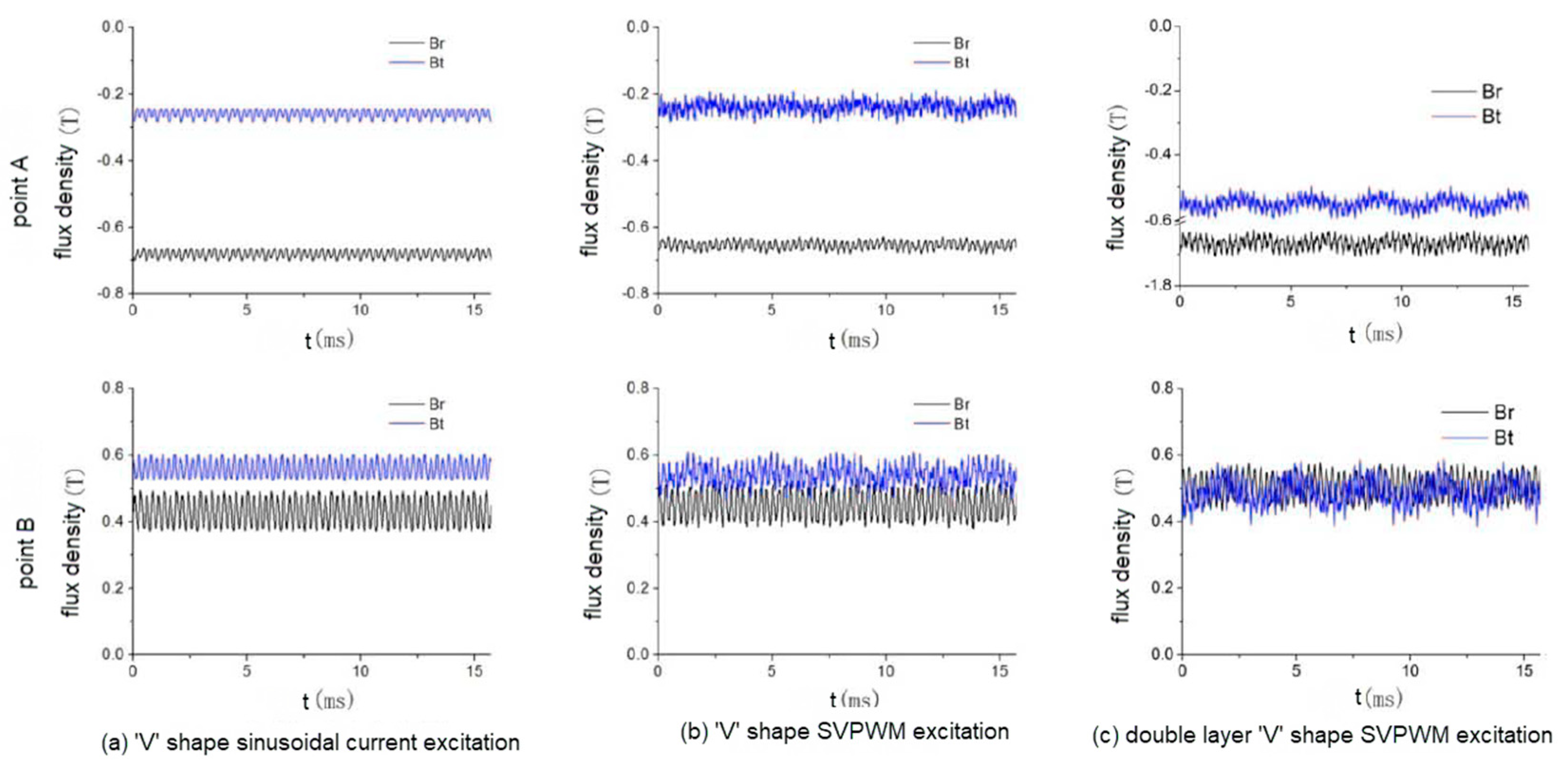
Figure 8 and the flux density waveform under the rated load at the same position points A and B on the motor rotor is shown in
Figure 9. Point A is on the q axis and point B is on the d axis.
As can be seen from
Figure 7 and
Figure 8, magnetic leakage on the rotor is obvious and the magnetic isolation position is prone to local saturation. The double V-type IPMSM has more partial saturation due to the large number of permanent magnets and magnetic isolation. According to the position Angle θ0 = 60° and the electrical Angle θr = 20° at the end of the adjacent flux barrier, the double V-type rotor structure is more reasonable. Under normal circumstances, due to the rotor size and magnetic steel size, it is impossible to change the channel position θ0 without changing θr. When the samarium–cobalt permanent magnet with a relatively small magnetic energy product is used to design a double V-type rotor structure, the options of θ0 and θr are limited. If the permanent magnet material with a higher magnetic energy product is used, the rotor structure of the multi-layer IPMSM can have more combinations of θ0 and θr.
Figure 9 shows the flux density waveform at points A and B on the rotor under rated load;
Figure 9a,b are the flux density waveform of the V-type IPMSM under the load of sinusoidal current source and SVPWM. By comparison, it can be seen that the calculated flux density changes are smooth under the condition of a sinusoidal current source and the time harmonics under SVPWM loading increase significantly. In the process of motor design, if only the motor loss under the load of a sinusoidal current source is considered, it is likely that the rotor heat dissipation design is unreasonable due to the small rotor loss; even the motor is damaged due to the rotor overheating.
Figure 9b,c shows the flux density waveforms of V-type and double V-type IPMSMs under SVPWM loading. Under rated load conditions, the flux density amplitude at point B on the d-axis is very close but the amplitude of double V-type IPMSMs fluctuates more.
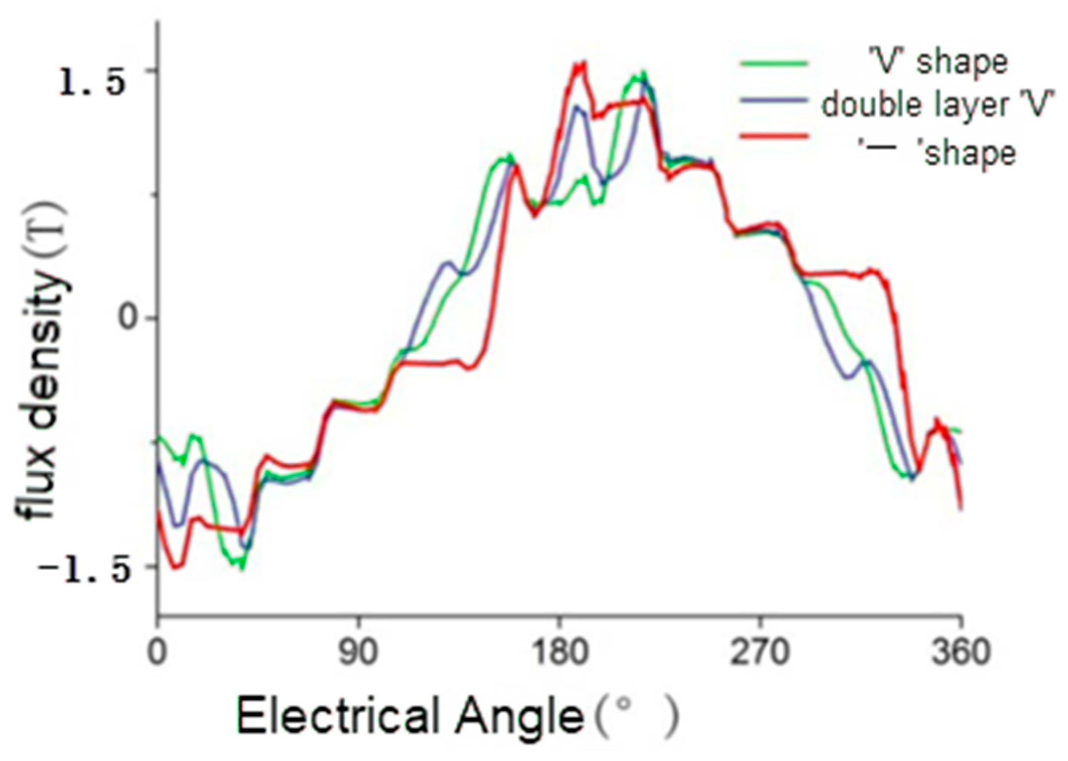
Figure 10 shows the air gap flux density of “一”-type, V-type, and double-V-type IPMSMs under a rated load. Compared with “一”-type, air gap flux density of the V-type and double-V-type is closer to sine.
In the electromagnetic field analysis of the motor, the excitation sources generally include a sinusoidal current source, a sinusoidal voltage source, and inverter space vector pulse width modulation (SVPWM). The loss analysis results of the sinusoidal current source and sinusoidal voltage source are similar to some extent. Therefore, harmonic analysis of current and flux density under two excitation modes of sinusoidal current source and SVPWM will be carried out; the influence of harmonic on loss results will be further analyzed.
The A-phase current of the sinusoidal current source of the V-type IPMSM and the rated load of the SVPWM excitation are shown in
Figure 11. It can be seen that the current harmonics under the SVPWM power supply are obvious. Harmonic analysis of the A-phase current is carried out and the A-phase harmonic current, as shown in
Figure 12, is obtained.
As can be seen from
Figure 12, the harmonic current under the sinusoidal current source is mainly a low-order harmonic current and the amplitude of harmonic current is relatively small. The main harmonic current number under SVPWM power supply is 23.5 ± 2.23.5 ± 4.47 ± 1.71 ± 2, that is, 19, 21, 22, 25, 26, 28, 46, 48, 69, and 73 times.
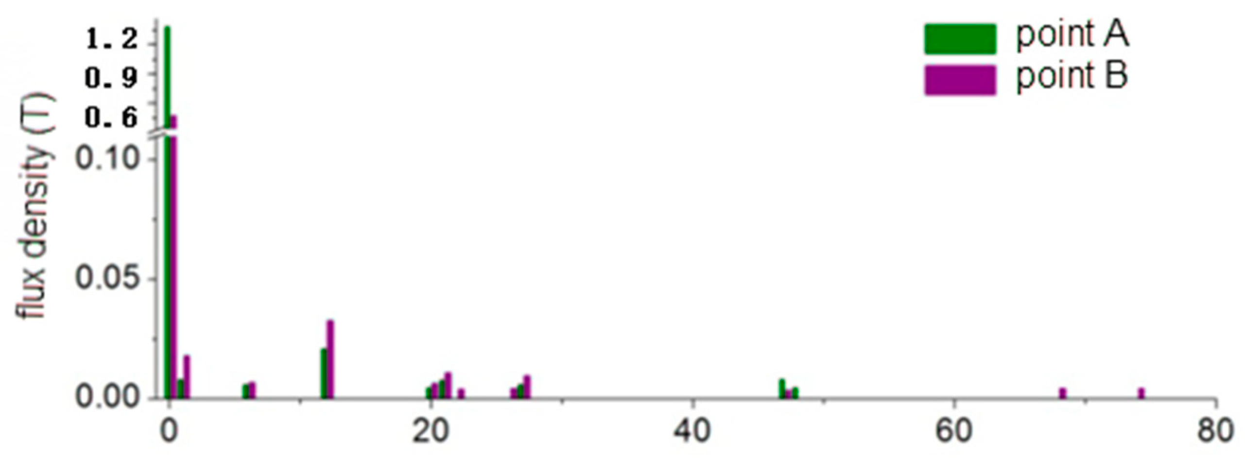
The amplitude of flux density harmonic components at point A and point B of the sinusoidal current source and SVPWM-rated load of V-type IPMSM is shown in
Figure 13. As can be seen from the figure, similar to the situation of A-phase harmonic current, the higher harmonics under the sinusoidal current source are less while the flux density harmonics under SVPWM are more.
The harmonic analysis results of an A-phase harmonic current and flux density under the SVPWM of double V-type IPMSM SVPWM are shown in
Figure 14 and
Figure 15. Compared with V-type IPMSM, the harmonic flux density of double V-type IPMSM is significantly reduced.
5.2. Calculation of Rotor Loss
The loss on the rotor of PMSM mainly includes two parts, namely, rotor core loss and PM loss. Due to the rotor heat, the dissipation condition is generally poor; the rotor loss in the PMSM under SVPWM will cause higher rotor temperature rise and even lead to irreversible demagnetization of permanent magnets and motor rotor burnout. The purpose of optimizing rotor structure is not only to reduce rotor core loss or PM loss but also to find the best motor design method to meet the requirements of electromagnetic load and thermal load of the motor. Therefore, on the basis of the analysis of motor current and rotor flux density, the rotor loss of the motor needs to be accurately analyzed.
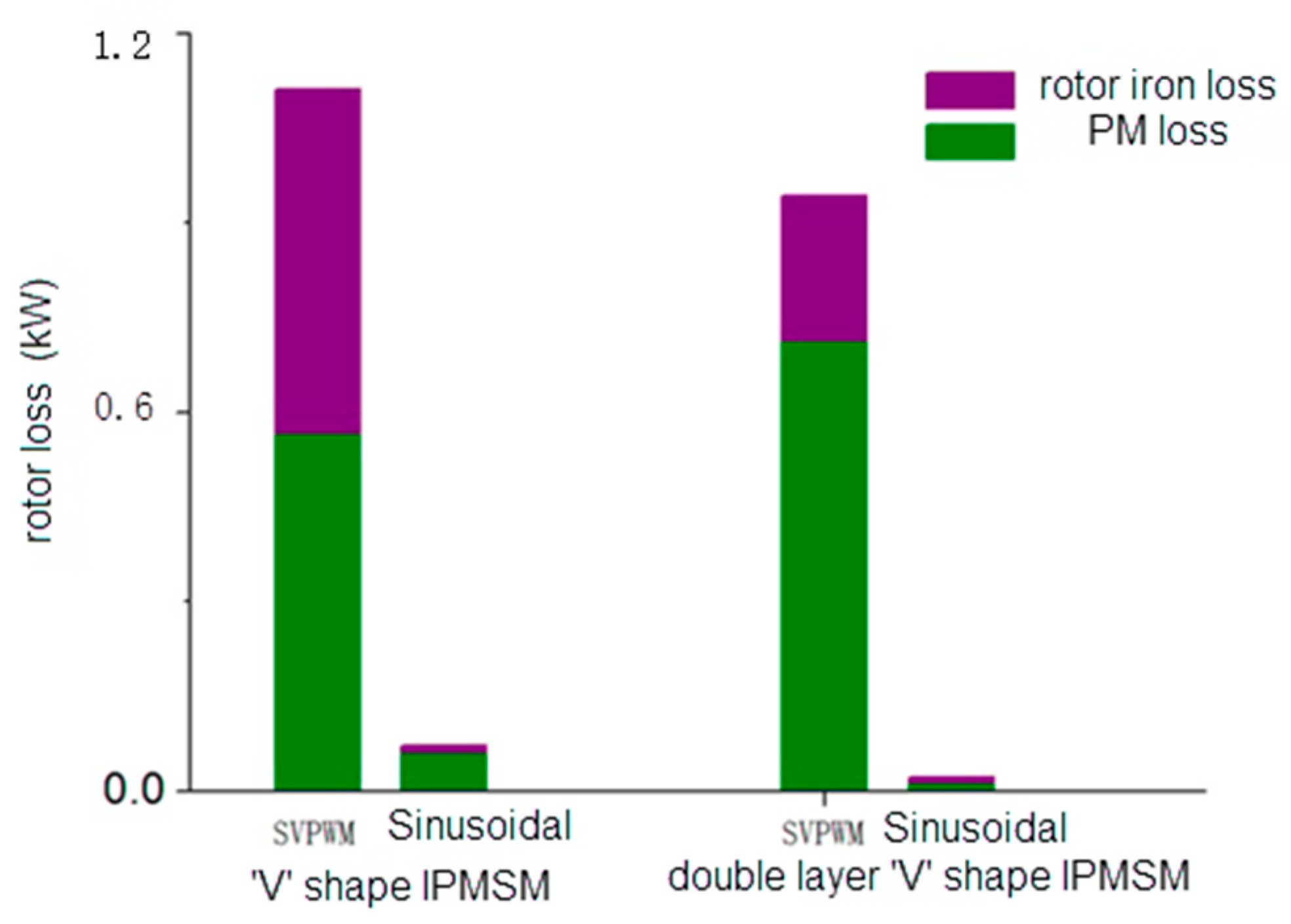
The rotor permanent magnet current density under SVPWM excitation at a certain time is shown in
Figure 16 and the rotor loss under sinusoidal current source and SVPWM excitation is shown in
Figure 17. As can be seen from the figure, the rotor loss under the sinusoidal current source is very small which is inconsistent with the actual situation. In the process of studying rotor loss, the results of the sinusoidal current may seriously underestimate the temperature rise of the rotor. Under the excitation of SVPWM, the loss of permanent magnet of double V-type IPMSM is higher than that of V-type. However, relative to the reduction in stator current time harmonic component, the flux density harmonic component in the stator rotor core is also reduced and the rotor core loss of the double V-type IPMSM is much lower than that of the V-type.
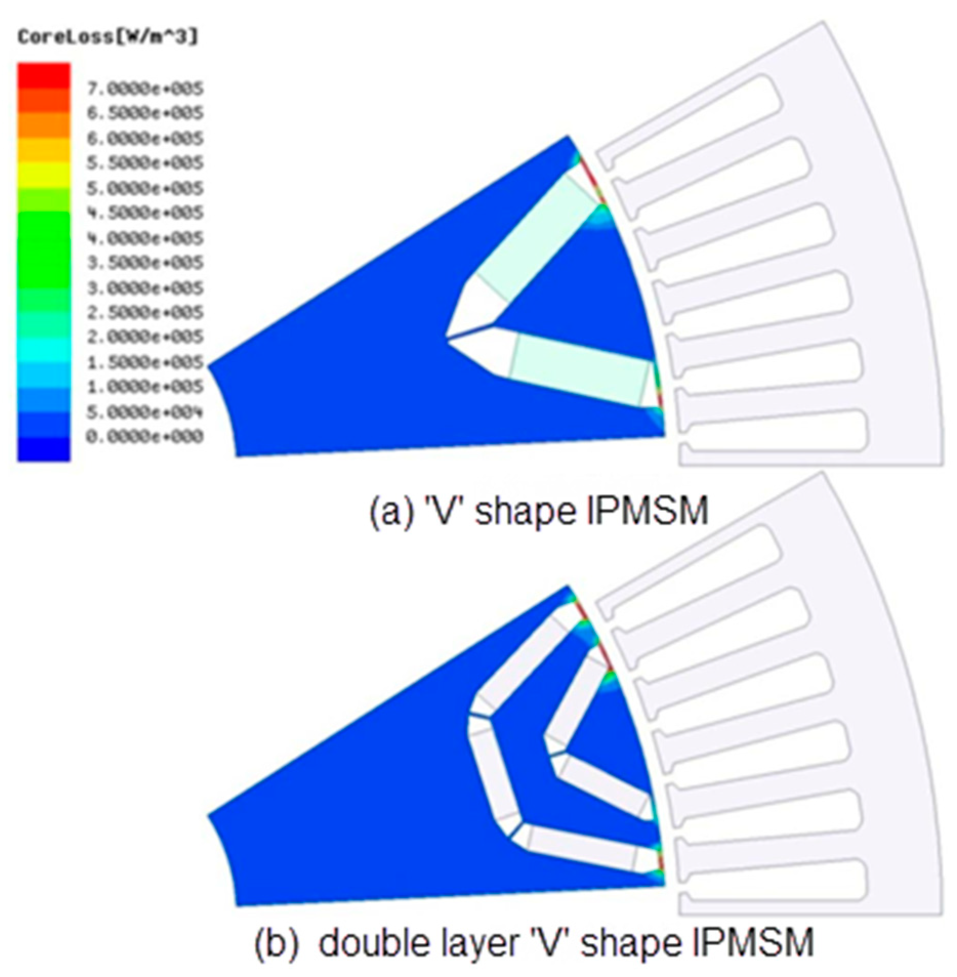
The distribution cloud diagram of rotor core loss is shown in
Figure 18. The eddy current caused by harmonic magnetic field is concentrated on the rotor surface so the rotor eddy current loss is mainly concentrated on the rotor surface, especially at the flux density saturation.
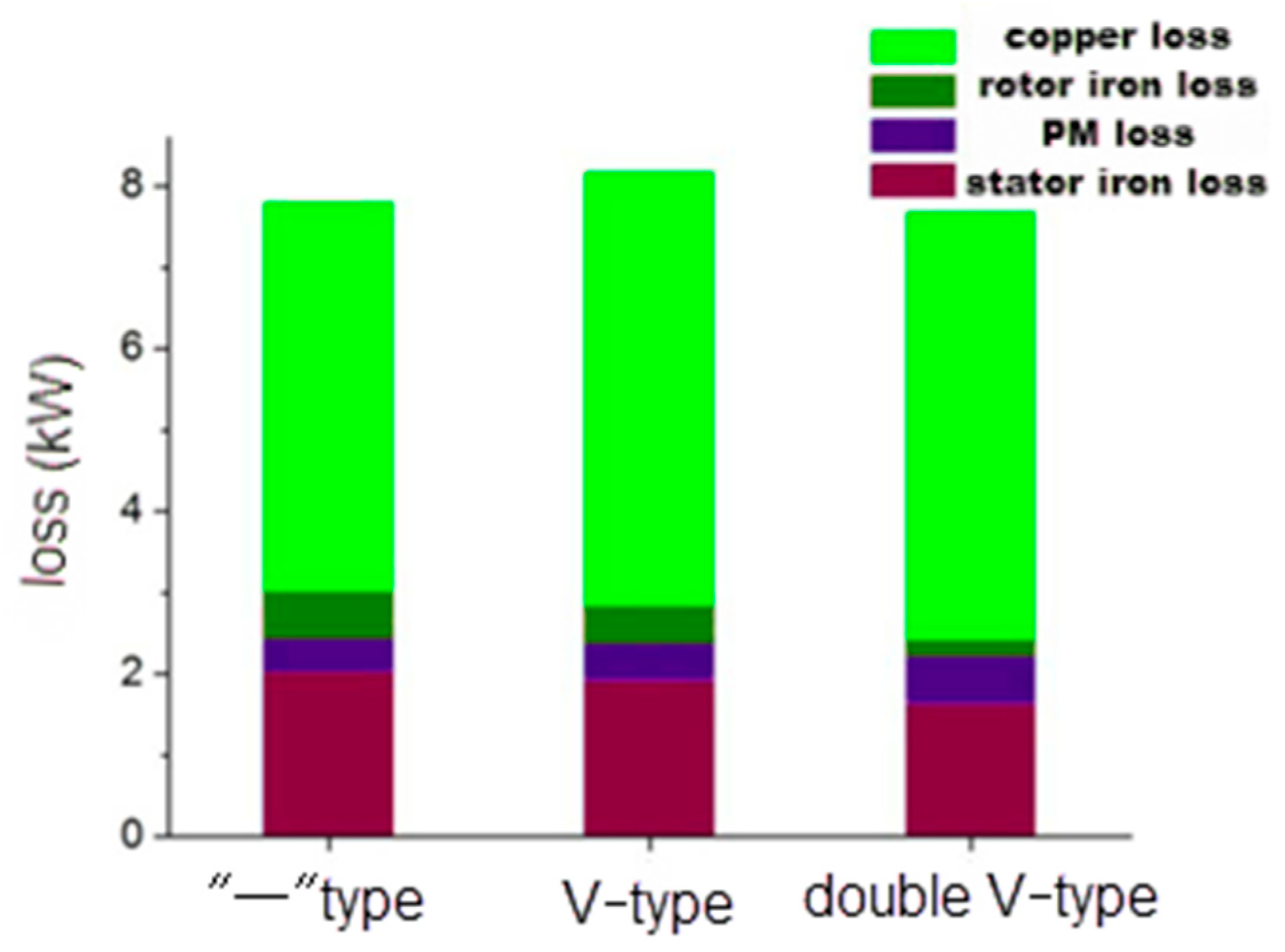
The losses of “一”-type, V-type, and double V-type IPMSMs are shown in
Table 3 and
Figure 19. The loss changes (%) of V-type and double V-type are based on the “一” type. As can be seen, the rotor core loss of the V-type and double V-type IPMSMs is significantly reduced compared to the “一” type. Even if the loss of permanent magnet is increased, the total rotor loss is still reduced. The way of optimization is to change the arrangement of permanent magnets. The change in magnetic circuit and the increase in magnetic leakage inevitably lead to the reduction in back EMF of no-load. Under the same load requirements, the copper loss increases with the increase in the current and the eddy current increases with the increase in the time harmonic current. However, after optimization, the air gap flux density is closer to sine and the reduction in space harmonics leads to the reduction in stator core loss and rotor core loss. Compared with the “一” type IPMSM, the winding loss of the V-type is increased and the core loss is reduced. The core loss of the double V-type IPMSM is significantly reduced.
6. Experimental Verification
At present, there are few experimental verification methods for permanent magnet loss, including the loss separation method and direct measurement method.
The loss separation method is to subtract other types of losses (stator and rotor iron loss, winding copper loss, mechanical loss, etc.) during the operation of the permanent magnet synchronous motor from the total loss obtained to obtain the permanent magnet loss. This method is simple and easy to implement. However, this method usually inherits the errors of other loss measurements, resulting in larger errors in the measurement of permanent magnet losses.
The direct measurement method needs to accurately predict the temperature change in the permanent magnet through a temperature sensor and then obtain the permanent magnet loss according to the temperature field model of the motor. The arrangement of the temperature sensor in the rotor is limited and it will have a certain impact on the structure of the rotor and the electromagnetic field of the motor. The implementation of this method is more difficult.
After comprehensive consideration, the correctness of the simulation results is verified by the total electromagnetic loss of the motor. The purpose is to no longer separate the losses. Thus, the measured eddy current loss of the permanent magnet is prevented from inheriting other losses.
Two prototype rotor cores of V-type and double V-type are manufactured, as shown in
Figure 20.
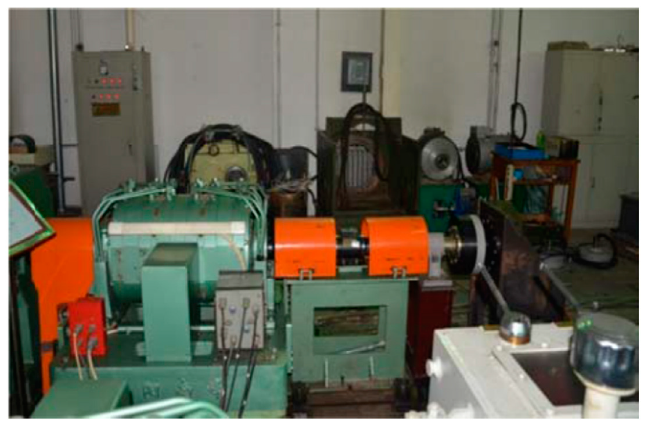
Figure 21 shows the test bench.
Under light load conditions (to the same as in
Table 3), the total input power of the PMSM is measured by the power analyzer and the output power is obtained by connecting the torque sensor on the rotor side of the PMSM. Then, the total loss of the PMSM is the difference between the input power and the output power. The electromagnetic loss of PMSM is obtained by subtracting the mechanical loss from the total loss.
The output power of the double V-type IPMSM is about 68.5 kW while the input power is about 85 kW. For the V-type IPMSM, the output power is about 70 kW while the input power is about 85 kW.
In the preceding experiment, it was learned that the other loss of the V-type IPMSM was about 7 kW.
According to Li Chunlan’s research in [
23], the empirical formula for mechanical loss is as follows:
where
K is the empirical coefficient and the general value is
;
L is the length of the motor;
n is the speed of the motor;
D is the outer diameter of the motor stator core.
It can be seen that the rotor topology is not a factor affecting the mechanical loss. Therefore, the mechanical loss of double V-type IPMSM and V-type IPMSM are the same at the same structural size and the same speed. In other words, the mechanical loss of double V-type IPMSM is also 7 kW.
Therefore, it can be calculated that the electromagnetic losses are 9.5 kW and 8 kW, which is basically consistent with
Table 3 (8.13 kW and 7.75 kW, respectively). The errors are 15% and 3%, respectively.
The error may be due to the following reasons:
- (1)
There are errors in the experimental and simulation results of the two motors which may be due to the unseparated errors that lead to the difference between the experimental and the simulation results;
- (2)
The error for double V-type IPMSM is larger, which may be because the empirical Formula (2) can be further optimized by considering more factors. Thus, it is more accurate to speculate the mechanical loss of double V-type IPMSM.
7. Conclusions
The research in this paper can provide reference for the loss analysis and optimization and rotor structure selection of rare earth permanent magnet synchronous motor rotor design. The space harmonic magnetic field caused by motor structure and the time harmonic magnetic field caused by non-sinusoidal stator current lead to rotor core loss and PM loss in the rotor of PMSM. The rotor loss caused by space harmonics and time harmonics caused by PWM excitation is analyzed. The main work and conclusions are as follows:
- (1)
In the area of weak magnetism, the radial and tangential flux density at different positions on the rotor at different speeds are analyzed. With the increase in rotational speed, the weak magnetic current increases, the amplitude of flux density in the rotor core decreases, and the eddy current loss of the rotor core also decreases. The higher the upper part of the rotor is affected by the harmonic current magnetic field, the larger the corresponding loss. Therefore, the core loss on the rotor is mainly distributed in the outer part of the rotor;
- (2)
Based on the “一” type IPMSM, the magnetic field analysis and loss calculation of the V-type and double V-type IPMSM are carried out by optimizing the rotor structure. After optimization, the air gap flux density of the double V-type is closer to sine than that of V-type IPMSM.
Comparing the analysis results of rotor loss under the excitation of sinusoidal current and SVPWM, it can be seen that the rotor loss under the load of sinusoidal current is very small. The influence of time harmonics on the eddy current loss of the rotor must be considered in the analysis of eddy current loss.
Based on the analysis of this paper and the current development trend of rare earth permanent magnet synchronous motors, the influence of subsequent control algorithms and the innovation of optimization algorithms should be further studied. At the same time, it is difficult to separate and measure the rotor loss from other losses in the rotating working condition and its experimental principle and design are worthy of further research.


