Abstract
The suppression of torque ripples in an interior permanent magnet synchronous motor (IPMSM) is essential to improve its efficiency and responsiveness. Here, we report on the development of an electromagnetic energy harvester incorporated into an IPMSM to suppress its torque ripples. The proposed harvester is driven to oscillations by the speed ripple of the AC motor. We derived the motion and circuit equations for the motor and the harvester according to Euler–Lagrange equations. We discussed the principle of electrical power generation and used MATLAB/Simulink numerical simulations to investigate the dynamic behavior of the proposed harvester. Our findings revealed that the active Coriolis force unnecessarily reduces the motor’s original torque, leading to unsuccessful power generation. Nevertheless, our results demonstrated that the reactive Coriolis force successfully suppresses the motor torque ripple.
1. Introduction
Interior permanent magnet synchronous motors (IPMSMs) are widely used in industrial applications due to their high efficiency and high power density [1]. However, their intrinsic operational principle leads to inevitable torque ripples caused by the space harmonics of the magnetic flux and the time harmonics of the output voltage. IPMSMs contain various kinds of space harmonics of the magnetic flux in the air gap due to the saliency of the stator and the rotor. Moreover, the pulse width modulation (PWM) inverter and square-wave drives include odd-order time harmonics of the winding current. These harmonic components generate torque ripples that increase the noise and vibration and reduce the motor’s responsiveness without contributing to the motor’s output.
The suppression of torque ripples in IPMSMs has been reported in the literature considering the motor’s structure and control. The structural approach includes methods based on skewing the rotor [2] and optimizing the shapes of the permanent magnet and the iron core in the rotor [3,4,5]. One method was reported as a control approach based on the estimation and the control of instantaneous torque ripples using motor constants [6,7,8].
We proposed a different approach to suppress torque ripples using the Coriolis force generated by the radial vibration of a linear oscillatory actuator (LOA) [9,10]. The Coriolis force is caused by the resonant behavior of the LOA’s mover, which oscillates radially in the rotational coordinate of the rotor. The LOA resonates by matching the frequency of the centrifugal force ripple received by the LOA mover to its natural frequency. Furthermore, the control of the LOA’s current can be used for actively controlling the Coriolis force. However, this method requires a set of elements, including an external power supply to drive the LOA, a controller, and slip rings for power and signal transmission to the LOA installed on the rotor’s surface. The combination of these elements results in a large motor drive system. The present study proposes a new method to eliminate the external power supply by operating the IPMSM as an electromagnetic energy harvester. Energy harvesting techniques have been developed in the past decade, including piezoelectric [11,12,13] and electromagnetic [14,15,16]. However, no literature has noted that the torque ripple of a motor can be a source of energy for vibration power generation. This paper investigates and clarifies the feasibility of the energy harvester oscillated by torque ripple of the AC motor. The proposed suppression method in this paper is advantageous because it can be combined with existing suppression methods.
This paper is organized as follows. In Section 2, a mathematical model is derived based on the Euler–Lagrange equations. In Section 3, numerical simulations using MATLAB/Simulink reveal that the electrical power generation and the suppression of torque ripples can be achieved concurrently. In Section 4, energy flow of the proposed harvester is discussed.
2. Electromagnetic Energy Harvester Oscillated by Speed Ripple of Motors
2.1. Mathematical Model
A simplified schematic of the proposed energy harvester system is shown in Figure 1; the stator of the motor and other components are not depicted. Two energy harvesters are mounted symmetrically on the surface of the rotor. The motion of their movers in the radial direction is synchronized with the rotational motion of the rotor. The stator and the coil of the LOA are stationary in the rotating coordinate of the rotor. The permanent magnets on the movers oscillate laterally relative to the coil, resulting in a power-generating back electromotive force (EMF). The axial distance between the energy harvesters and the rotor is assumed to be sufficiently large to prevent flux interferences. In contrast to the systems studied in previous work [9,10], this energy-harvesting system requires neither an external power supply nor a controller. Nonetheless, a slip ring is still necessary for externally extracting the generated electrical power.
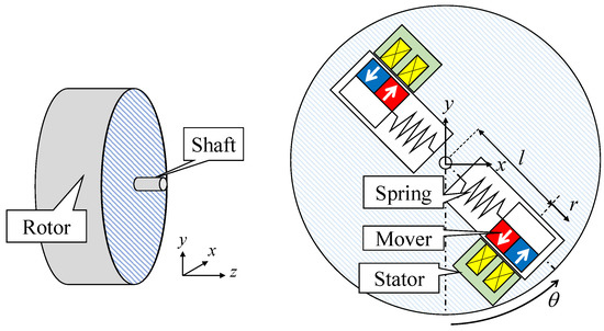
Figure 1.
Configuration of the proposed energy harvester.
The equations of motion for the energy harvester and the AC motor are given by the Lagrangian equations as follows:
Here, J is the rotor’s moment of inertia, is the rotational angle of the rotor, l is the initial length from the origin, r is the radial displacement of the harvester, is the viscous damping coefficient for the rotational motion, is the output torque of the AC motor, is the load torque, is the viscous damping coefficient for the radial oscillation, is the spring stiffness of the harvester, is the thrust constant of the harvester, and I is the current caused by electromagnetic induction. The detailed mathematical model can be found in [10,17]. In (1), the multiple harvester oscillators are treated as single equivalent inertia m. The fourth term on the left side of (1) is the Coriolis force acting on the rotor, and the first term on the right side of (2) is the centrifugal force acting on the harvester’s oscillator. The electrical circuit equation of the harvester’s coil is
where is the coil resistance of the harvester and is the load resistance. For simplicity, the position and current dependence of the coil inductance L and the generation constant were ignored.
2.2. Operational Principle of Power Generation
In this section, we compare the power generation conditions of the proposed energy harvester with those reported in the authors’ previous study [10]. The power generation principle in the proposed harvester is illustrated in Figure 2. A rotational vibration system was assumed in [10], in which the rotor was connected to a fixed surface via a torsional spring. Hence, the motion of the rotor was a rotational vibration rather than a steady rotation. The ratio of the torsional motion’s frequency (see the second row in Figure 2) to the natural frequency of the oscillator (see the fourth row in Figure 2) was set to 1:2 to induce a parametric excitation and suppress the torsional vibration effectively. A different condition is required for the power generation in the energy harvester proposed in this study. Only the sixth-order component (i.e., the largest component) is assumed for the torque ripple of the AC motor [18], which induces a speed ripple at the same frequency in the rotor. The centrifugal force ripple caused by this speed ripple drives the harvester’s movers into oscillation in the radial direction. The frequency of the centrifugal force ripple matches that of the speed ripple because the DC component (constant rotation) is dominant compared with the AC component (ripple). Therefore, matching the natural frequency of the harvester with that of the centrifugal force ripple (i.e., a frequency ratio of 1:1) induces resonance and maximizes the vibration displacement of the harvester. Electric power is generated in the harvester by electromagnetic induction resulting from the relative motion of the permanent magnet and the coil. At the same time, the torque ripple is suppressed by the Coriolis force acting on the rotor due to the harvester’s vibration. The harvester’s mass and spring constant should be adjusted to match the frequency of the torque ripple and the natural frequency of the harvester.
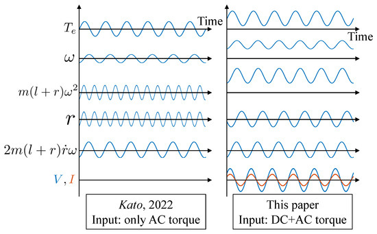
Figure 2.
Principle of the electrical power generation in the proposed harvester compared with that reported in [10].
3. Numerical Simulation Results
3.1. MATLAB/Simulink Model and Condition
The mathematical model in Equations (1)–(3) contains several adjustable parameters. As the motion equations are nonlinear differential equations due to the centrifugal force and the Coriolis force, they should be solved numerically rather than analytically. For this reason, we performed numerical simulations using MATLAB/Simulink to clarify the effect of each parameter on power generation. The 1D model of the IPMSM (JMAG-RT model) [19] shown in Table 1 was selected as the target motor. Only the torque constant and moment of inertia in Table 1 were used as reference values. Table 2 lists the additional calculation conditions.

Table 1.
Specifications of the selected IPMSM model.
Table 2.
Simulation conditions.
3.2. Verification of the Operational Principle
The power generation principle described in Section 2 was verified numerically, as shown in Figure 3, using the conditions listed in Table 2. The obtained waveforms are qualitatively similar to those shown in Figure 2. The simulation results indicated an average power generation of 1.9 mW and an amplitude value for the oscillator displacement equal to 0.41 , which is acceptable for the design of a harvester with feasible size.
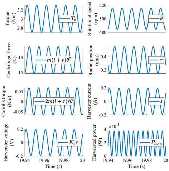
Figure 3.
Numerical verification of power generation.
3.3. Parametric Study of the Power Generation
3.3.1. Oscillator Mass and Frequency Ratio
The oscillator mass of the harvester is an independently adjustable parameter. Moreover, the spring constant can be used to adjust the ratio of the torque ripple’s frequency to the natural frequency of the harvester. Here, we investigate the effects of these two parameters on power generation through numerical simulations, as shown in Figure 4. The oscillator mass m was increased from 0.01 kg to 1 kg while the arm length l was simultaneously decreased to maintain the equivalent moment of inertia constant (2.5 × 10 ). When the mass of the oscillator m = 0.01 kg, the arm length l = 158 mm, which is considerably larger than the stator outer diameter. In this case, Figure 4 shows that more power is generated as the oscillator mass decreases (i.e., the arm length increases). Although the principle explained in Section 2.2 suggested that the amount of power generation is maximized for a frequency ratio of 1:1, the simulation results indicated a maximum power generation for ratios smaller than 1. We attributed this difference to the effect of the harvester’s viscosity.
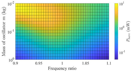
Figure 4.
Simulated results of harvested power as a function of mass and frequency ratio.
The corresponding results of the torque ripple’s reduction rate are shown in Figure 5. Positive and negative values correspond to a decrease and an increase in the torque ripple, respectively. The results indicated that the torque ripple could be suppressed mainly in the region where the frequency ratio was greater than 1, which deviates from the region of maximized power generation, as shown in Figure 4. Consequently, a frequency ratio larger than one was selected as a reasonable condition for concurrent power generation and torque ripple suppression.

Figure 5.
Simulated results of the torque ripple reduction rate as a function of the mass and frequency ratio.
3.3.2. Rotational Speed and Torque Ripple
Motor speed is essential when selecting a motor for the harvesters. Here, we numerically investigated the effects of the motor’s speed and the torque ripple’s amplitude on power generation. The computed results are shown in Figure 6, where the motor’s speed was varied from 50 rpm to 1000 rpm, and the torque ripple’s amplitude was varied from 0.3 to 3 . The result showed that the amount of power generated decreased as the rotation speed increased. According to (2), the mechanical response of the motor’s rotor is a first-order lag system, and the amplitude of the velocity ripple decreases with increasing speed (i.e., increasing the torque ripple’s frequency). It follows that the centrifugal force ripple, which is the source of the harvester’s excitation and the resultant power generation, decrease. Therefore, this harvester is suitable for use in the low-speed operation regime of the motor.
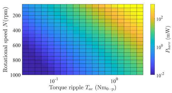
Figure 6.
Simulated results of harvested power as a function of rotational speed and torque ripple amplitude.
Furthermore, we performed a regression analysis on the results in Figure 6, which showed that the amount of power generation increased proportionally to the square of the torque ripple’s amplitude. Moreover, the amplitude of the oscillator’s displacement increased linearly with that of the torque ripple. Consequently, the amount of generated power increased proportionally to the square of the linearly increasing voltage (i.e., if the generated voltage is V, the amount of generated power is ). Figure 7 shows the computed results of the torque ripple’s reduction rate for the conditions shown in Figure 6. The results indicate that this reduction rate is independent of the torque ripple’s amplitude. In addition, they show that it decreased in the low-speed range, where an increase in power generation was expected, taking negative values in some regions. To further examine the cause of these observations, we performed calculations using a rotational speed of 50 rpm and a torque ripple amplitude of 3 . In this case, the AC (ripple) component was dominant over the DC (constant rotation) component of the rotation speed. As a result, higher-order components (12th and 18th order), rather than the assumed 6th-order rotational component, were superimposed on the centrifugal force ripple. Therefore, the torque ripple could not be suppressed, which does not satisfy the original power generation principle described in Section 2 and Section 3.2. The numerical simulation revealed that the proposed harvester deviates from the assumed power generation principle and loses its suppression effects when the allowable torque ripple amplitude is exceeded.
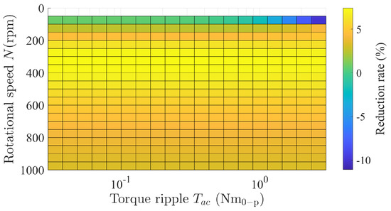
Figure 7.
Simulated results of the torque ripple’s reduction rate as a function of rotational speed and torque ripple amplitude.
3.3.3. EMF Constant and Impedance Matching
The energy harvester’s EMF constant can be adjusted by designing the flux linkage through the coil. Several factors determine the flux linkage, including the permanent magnets’ grade, the number of turns, and the magnetic path’s design to achieve a high air gap flux density. Moreover, the maximum power transfer theorem [20] is expected to play an important role. It states that power generation is maximized when the coil and load resistance are equal. Nonetheless, the relationship between this theorem and the torque ripple suppression remains unclear. Here, we numerically investigated the effects of the EMF constant and impedance matching on power generation.
Figure 8 shows the simulated result for power generation. Our results showed that as the power generation constant increased, the corresponding maximum point deviated from the theoretical value of impedance matching, = 1. Moreover, Figure 9 shows the calculation results of the torque ripple’s reduction rate for the power generation conditions shown in Figure 8. Although the reduction rate was positive in all regions, the region of maximum value conflicted with that of maximum power generation. Therefore, these characteristic maps may be useful for the designing this harvester’s magnetic circuit.
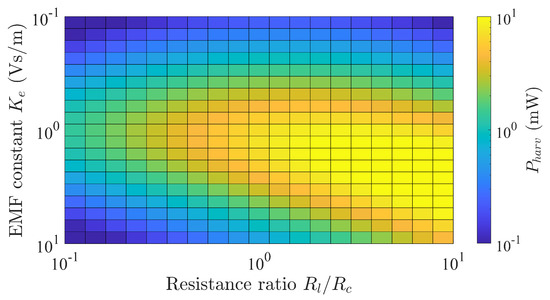
Figure 8.
Simulated results of harvested power as a function of load resistance and EMF constant.
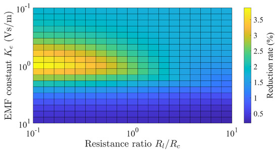
Figure 9.
Simulated results of the torque ripple’s reduction rate as a function of load resistance and EMF constant.
4. Discussion on Energy Flow
In Section 3, we evaluated the effects of the motor’s and harvester’s parameters on power generation. However, the mechanism by which the reactive mechanical output, which is the product of the torque and speed ripples, transfers energy to the harvester for power recovery was unclear. Here, we numerically simulated the energy flow to clarify active and reactive power transfer. To convert the differential Equations (1)–(3) into the power dimension, we multiplied both sides of each equation by the rotor’s angular velocity , oscillator velocity , and current I flowing in the coil of the harvester, respectively. The following three equations are obtained:
Figure 10, Figure 11 and Figure 12 show the time variation of the energy flow calculated from the numerical results in Figure 3, based on Equations (4)–(6), respectively. Our results (Figure 10) indicated that the active mechanical power of the motor (157 W) was converted into active mechanical power due to the load torque and mechanical loss (i.e., viscous friction). The active power due to the Coriolis force was approximately 100 mW on average. In other words, the active mechanical power due to the Coriolis force acted as a load torque, whereas the reactive mechanical power (35) was distributed to the load torque, rotor inertia, equivalent inertia of the oscillator, viscosity, and Coriolis force. Moreover, Equations (4) and (5) suggest that the active and reactive mechanical powers due to the Coriolis force are transferred to the harvester as active and reactive powers via the centrifugal force. In our simulations, the active mechanical power (50 mW) was distributed into mechanical power (3.8 mW) due to the harvester’s electromagnetic force and a mechanical loss (46.2 mW) due to viscous friction. In contrast, the reactive power due to centrifugal force was distributed to all other terms. It is clear from Equations (5) and (6) that the mechanical power due to the electromagnetic force is equivalent to the electrical power due to the power generation by electromagnetic induction. This mechanical output (3.8 mW) is converted into Joule losses due to the coil and load resistances, yielding = 1.9 mW of electric power.
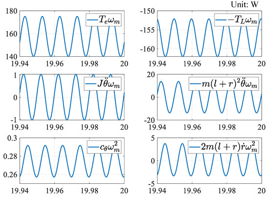
Figure 10.
Mechanical energy flow for motor.
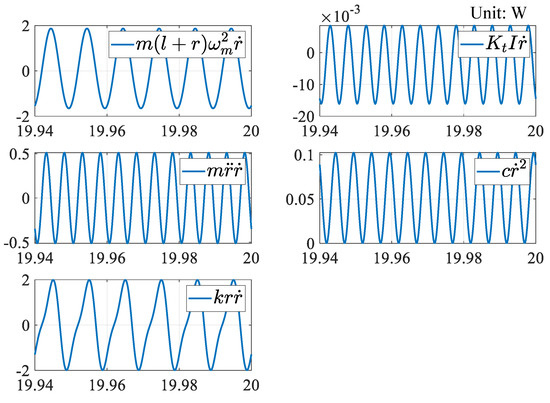
Figure 11.
Mechanical energy flow for harvester.
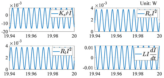
Figure 12.
Electrical energy flow for harvester.
The above energy transfer mechanism suggests that the proposed harvester merely receives a part of the motor’s active mechanical power, and cannot regenerate the reactive power of the motor caused by the torque ripple. However, because this harvester uses the velocity ripple caused by the torque ripple as an excitation source, energy is transferred from the mechanical system of the motor to the mechanical and electrical systems of the harvester, triggered by the reactive power. The Coriolis force is successfully generated in the process of energy transfer and works to suppress the torque ripple. When this harvester is installed in an AC motor, the Coriolis force’s effective output is part of the mechanical load. It reduces the motor’s effective output, whereas the reactive output of the Coriolis force suppresses the torque ripple.
5. Conclusions
In this study, we proposed an energy harvester that uses the centrifugal force ripple caused by the speed ripple of an AC motor as the excitation source. We showed, through numerical simulations, that the reactive mechanical power of the motor could not be regenerated as electrical power. Furthermore, we demonstrated that the reactive mechanical power indirectly excites the mover of the harvester, which produces the Coriolis force suppressing the torque ripple.
The proposed suppression method in this paper is advantageous because it can be combined with existing suppression methods. Condition monitoring of AC motors can be a possible application because the proposed energy harvester is able to generate electrical power directly from the torque ripple. In the future, we plan to optimize an energy harvester by using finite-element-based electromagnetic analysis and develop a prototype for experimental verification.
Funding
This research was supported by JKA and its promotion funds from KEIRIN RACE.
Data Availability Statement
Not applicable.
Conflicts of Interest
The authors declare no conflict of interest.
References
- Sul, S.K.; Kim, S. Sensorless Control of IPMSM: Past, Present, and Future. IEEJ J. Ind. Appl. 2012, 1, 15–23. [Google Scholar] [CrossRef]
- Jahns, T.M.; Soong, W.L. Pulsating Torque Minimization Techniques for Permanent Magnet AC Motor Drives-A Review. IEEE Trans. Ind. Electron. 1996, 43, 321–330. [Google Scholar] [CrossRef]
- Totoki, E.; Yamaguchi, S.; Tanaka, T.; Ito, K.; Daikoku, A.; Morimoto, S. Torque Ripple Reduction for Permanent Magnet Motor using New Configuration for Concentrated Windings. IEEJ J. Ind. Appl. 2022, 11, 531–537. [Google Scholar] [CrossRef]
- Hiramoto, K.; Takeda, Y.; Sanada, M.; Morimoto, S. Torque Ripple Reduction of Reluctance Torque Assisted Motors Using Asymmetric Flux Barriers. IEEJ J. Ind. Appl. 2004, 124, 208–214. [Google Scholar] [CrossRef]
- Yamamoto, Y.; Morimoto, S.; Sanada, M.; Inoue, Y. Reduction of Torque Ripple in Synchronous Reluctance Motor by Combining Different Flux Barrier Structures. IEEJ J. Ind. Appl. 2019, 8, 430–436. [Google Scholar] [CrossRef]
- Nakamura, K.; Fujimoto, H.; Fujitsuna, M. Torque Ripple Suppression Control for PM Motor Considering the Bandwidth of Torque Meter. IEEJ J. Ind. Appl. 2010, 130, 1241–1247. [Google Scholar] [CrossRef]
- Nakao, N.; Akatsu, K. Torque Ripple Control Based on Instantaneous Torque Estimation in PMSMs. IEEJ J. Ind. Appl. 2011, 131, 1120–1227. [Google Scholar] [CrossRef]
- Qu, J.; Jatskevich, J.; Zhang, C.; Zhang, S. Torque Ripple Reduction Method for Permanent Magnet Synchronous Machine Drives With Novel Harmonic Current Control. IEEE Trans. Energy Convers. 2021, 36, 2502–2513. [Google Scholar] [CrossRef]
- Kato, M.; Naito, S.; Kitayama, F. Basic Study on Reduction of Rotational Vibration Using Linear Oscillatory Actuator. J. Jpn. Soc. Appl. Electromagn. Mech. 2021, 29, 309–314. [Google Scholar] [CrossRef]
- Kato, M.; Kitayama, F. Reduction of Rotational Vibration Using Coriolis Force Generated by Electromagnetic Oscillatory Actuator Moving in Radial Direction. IEEE Trans. Magn. 2022, 58, 8200205. [Google Scholar] [CrossRef]
- Sahoo, S.; Ratha, S.; Rout, C.S.; Nayak, S.K. Self-charging supercapacitors for smart electronic devices: A concise review on the recent trends and future sustainability. J. Mater. Sci. 2022, 57, 4399–4440. [Google Scholar] [CrossRef]
- Zhao, K.; Zhang, Q.; Wang, W. Optimization of Galloping Piezoelectric Energy Harvester with V-Shaped Groove in Low Wind Speed. Energies 2019, 12, 4619. [Google Scholar] [CrossRef]
- Ducharne, B.; Gupta, B.; Litak, G. Simulation of Synchronized-Switching Method Energy Harvester Including Accurate Piezoceramic Nonlinear Behavior. Energies 2019, 12, 4466. [Google Scholar] [CrossRef]
- Wang, H.; Shi, G.; Han, C. A Free-Standing Electromagnetic Energy Harvester for Condition Monitoring in Smart Grid. Wirel. Power Transf. 2021, 2021, 6685308. [Google Scholar] [CrossRef]
- Ibrahim, P.; Arafa, M.; Anis, Y. An Electromagnetic Vibration Energy Harvester with a Tunable Mass Moment of Inertia. Sensors 2021, 21, 5611. [Google Scholar] [CrossRef]
- Foisal, A.-R.-M.; Hong, C.; Chung, G.-S. Multi-frequency electromagnetic energy harvester using a magnetic spring cantilever. Sens. Actuators A Phys. 2012, 182, 106–113. [Google Scholar] [CrossRef]
- Viet, L.D.; Anh, N.D.; Matsuhisa, H. The effective damping approach to design a dynamic vibration absorber using Coriolis force. J. Sound Vib. 2011, 330, 1904–1916. [Google Scholar] [CrossRef]
- Su, T.; Hattori, S.; Ishida, M.; Hori, T. Suppression Control Method for Torque Vibration of AC Motor Utilizing Repetitive Controller with Fourier Transform. IEEE Trans. Ind. Appl. 2002, 39, 1316–1325. [Google Scholar]
- [RTML-001] PMSM/IPM Constant Rating 1000(W) 3-Phase. Available online: https://www.jmag-international.com/modellibrary/001/ (accessed on 30 November 2022).
- Thompson, S.P. Dynamo-Electric Machinery; A Manual for Students of Electrotechnics; Bibliolife: Charleston, SC, USA, 2009. [Google Scholar]
Disclaimer/Publisher’s Note: The statements, opinions and data contained in all publications are solely those of the individual author(s) and contributor(s) and not of MDPI and/or the editor(s). MDPI and/or the editor(s) disclaim responsibility for any injury to people or property resulting from any ideas, methods, instructions or products referred to in the content. |
© 2023 by the author. Licensee MDPI, Basel, Switzerland. This article is an open access article distributed under the terms and conditions of the Creative Commons Attribution (CC BY) license (https://creativecommons.org/licenses/by/4.0/).