1. Introduction
The efficient and environmentally friendly combustion of low-calorific value fuel mixtures is crucial for several applications such as waste heat recovery from gas turbine or high-temperature fuel cell off-gases [
1,
2]. The high inert content and very low calorific value of such mixtures reduces the flame temperatures and burning velocities, resulting in combustion stability issues. Gas streams with a poor combustible content require unique combustion technologies in order to face these challenges [
3,
4,
5]. Porous burner technology involving gas preheating and intense heat and radical recirculation has been shown, in general, to be able to extend stable combustion well below the mixture lean flammability limits.
Combustion in porous inert media offers significant advantages compared to gas-phase combustion in terms of both the efficiency and emissions. The general mechanism of combustion inside the porous media is that the premixed air–fuel reacts in the cavities of the material and, due to the characteristics of the porous media, the heat is recirculating (excess enthalpy) inside the porous structure [
4]. Porous burners are characterized by intense combustion due to the aforementioned heat recirculation phenomenon and enhanced hydrodynamic dispersion in the inert porous medium. The heat released via combustion is transferred to the solid phase, thereby increasing its temperature. The high thermal emissivity and thermal conductivity of the solid material compared with those of gases result in an enhanced heat transfer from the burned gases via combined conduction and radiation. This allows much higher preheating rates for the reactants compared to the common gas-phase combustion process. The phenomenon is called heat recirculation (enhanced enthalpy combustion) and leads locally to super-adiabatic temperatures. Further, depending on the porous material topology, there is enhanced cross-mixing of the gas stream due to the tortuous flow paths, which, in turn, enhances the transport of heat and intermediate species and increases the flame thickness (hydrodynamic dispersion). The combination of heat recirculation and hydrodynamic dispersion enables the efficient combustion of mixtures of low-energy content beyond the conventional gas-phase lean flammability limits. Further, a more homogeneous reaction zone is established with generally lower temperatures than the corresponding gas-phase flame. As a result, the flame stability is increased, and emissions are reduced [
6,
7]. Further, the low enthalpy rises and the homogeneous temperature field inside the burner results in very low NO
x emissions. With very lean operation CO (and unburned hydrocarbons), emissions can also be eliminated [
8,
9,
10,
11].
Multilayer coatings are being investigated on SiC foams as a way to increase the resistance of the material to thermal shock. By coating the surface with cordierite, the combustion efficiency is increased, resulting in significantly reduced CO and NO
x emissions [
12]. Additionally, SiC 3D printing is an emerging technology that can be exploited, as the printing of complex geometries of SiC structures for demanding applications is currently commercially feasible [
13].
In the present work, a novel foam burner design is proposed and experimentally evaluated for operation with very lean and highly diluted syngas mixtures. An extensive experimental campaign was carried out in order to evaluate the combustion stability and conversion efficiency of the burner as a function of the design and operating parameters.
3. Reactor Design
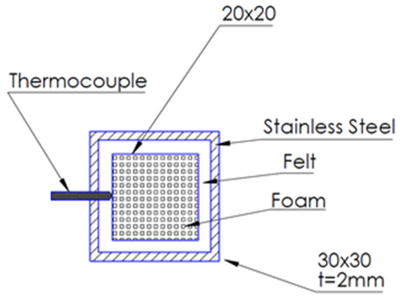
The total length of the stainless-steel reactor casing was 540 mm with a square cross-section of 26 × 26 mm. Two identical foams of 100 mm length each were placed at the center of the square pipe, resulting in an effective foam reactor length of 200 mm. The reactor casing was made of grade SS316 stainless steel, allowing for a high temperature and corrosion resistance. The spaces between the foams and the reactor walls were covered with insulating alumina–silica felt. Specifically, the foams were wrapped around via the insulating felt sheet, so that they were tightly canned inside the reactor (
Figure 1).
Temperature profiles along the foam length for different fuel and oxidizer stream introduction points are shown in
Figure 2. Thermocouples were placed along the reactor’s length in such a way as to obtain accurate and highly spatially resolved temperature measurements on the foam surface. A total of 18 sockets were drilled on the reactor wall, 16 located upon the foam area and 2 located at the front and rear end of the foam blocks, and the distance between the sockets was 12.5 mm each. The number of thermocouple measuring points on the foam surface was determined via allowing for a minimum acceptable distance between the sockets in order that the heat-affected zones (HAZs) of the welds did not affect one another and, thus, that material degradation was avoided. The minimum acceptable distance between two sockets was 15 mm, a restriction imposed also by machining requirements. For this reason, the reactor was drilled in a chevron pattern, as shown in
Figure 3. The thermocouples positioning along the burner surface is schematically shown in
Figure 3. The selected thermocouples were of K-type, with a measurement capability of up to 1250 °C.
The introduction of the fuel and oxidizer streams is crucial, as it affects both the flame stability and combustion performance. For this reason, some exploratory experimental tests were conducted in order to identify the optimum stream introduction pattern. Specifically, four different scenarios were examined for introducing reactants into the reactor, as graphically depicted in
Figure 4. The tests were conducted with the 20 ppi foam for the indicative Experiment 3 (
Table 2). In the first case, the fuel and oxidizer streams were introduced in the entrance of the pre-chamber at a distance of 18 cm upstream of the foam. In the second scenario, ¼″ stainless steel tubes were used as flow guides so that the introduction and mixing of the two streams took place downstream in the pre-chamber and at a distance of 5 cm from the foams. In the third scenario, the fuel guide was positioned in contact with the foam surface, while the oxidizer guide remained in a position 5 cm upstream, as in the previous case. In the final scenario, both the fuel and oxidizer stream guides were located so as to touch the front surface of the foam. In
Figure 2, the temperature rise along the length of the foam for each case is represented. It is obvious that, for the last case, the temperature rise along the body of the foam is significantly higher, which indicates that the ignition of the syngas is taking place in the foams and not in the front inlet part, so that pre-ignition due to the established temperature is avoided.
Based on the test results, the fourth scenario (i.e., both the fuel and oxidizer guides touching the foam surface) was selected as the optimum for stream introduction and employed for the remainder of the experimental test campaign.
Empirical and semi-detailed calculations have been performed in order to define the appropriate range of inlet mixture flowrates that can sustain stable combustion within the specific reactor and ceramic foam. In general, a flame is stabilized at the location/conditions where the fresh gas velocity equals the burning velocity. Accordingly, an estimation of the burning velocities for the given mixtures was performed. In the present work, a simplified engineering approach is utilized in order to calculate the burning velocity of the examined mixtures according to a semi-empirical correlation based on the work of Bedoya et al., 2017 [
6]. The correlation is based on the similarity between the Peclet numbers of free flames and flames stabilized in an inert porous media (i.e., the ceramic foam). The methodology used to obtain the foam flame speed and, consequently, derive the required flow rates for stable operation is the following. Adiabatic laminar flame speeds for freely-propagating mixtures with the same composition as those used in the current campaign are calculated using the CHEMKIN suite of the ANSYS software [
16] and the detailed kinetic mechanism proposed by Malliotakis et al. [
17]. The correlation in [
6] is then used in order to obtain the corresponding burning velocities inside the foam burner. Volumetric flowrates are then derived, assuming that the flow velocity equals the burning velocity.
Computations show that for very lean mixtures (λ > 5), the burning velocity in the foam burner is slightly less than that of the freely propagating flame. For moderately lean mixtures the foam structure induces flame speeds of a factor of 3 compared to the freely propagating flames. Based on the above analysis, total inlet flow rates at 300 K in the range of 4–25 lt/min were specified for the experimental campaign.
The flow in the porous medium is laminar. Based on Darcy’s velocity, an effective Reynolds number can be calculated through the expression on the basis of foam permeability, K = 2.33 × 10
−9 m
2, and porosity, ε = 0.88. The values of the viscosity (μ) and density (ρ) for the nitrogen at 700 °C, as nitrogen was utilized for the preliminary tests, are as such: μ = 4.1 × 10
−5 Pa×s, and ρ = 0.33 kg/m
3. The resulting Re = 0.06, which is well into the Darcy flow regime [
18].
The characteristic residence time based on the foam permeability and porosity is τres = 1 s.
4. Overall Experimental Setup
Both streams were precisely prepared with the aid of dedicated mass flow controllers (MFCs). With the use of a controlled evaporation mixer (CEM), the exact calculated mass of steam was introduced, and both the fuel and oxidizer flows were mixed up inside the reactor (
Figure 5). For both streams, insulated heated lines (200 °C) were used in order to avoid the condensation of the steam in the lines and also to introduce the streams at high temperatures. The reactor containing the foams was placed inside a high-temperature split tube furnace (Modular Tube Furnace, Universal Mounting, up to 1200 °C-FeCrAl Heater Split Tube, Length: 340 mm, Diameter: 78 mm, THERMANSYS) (
Figure 6a) and heated up to 700 °C. Insulation jackets were applied on the flanges in order to minimize the heating losses and to preserve the temperature uniformity on the foam blocks (
Figure 6b). A uniform heating zone of adequate size to accommodate the foam burner was established, and the reactor was aligned with the furnace centerline. The length of the uniform heating zone of the furnace is approximately 120 mm, as provided by the manufacturer and confirmed by preliminary measurements.
The temperature was measured on site via a set of thermocouples on the surface of the foams. The pressure drop along the porous reactor was measured using a differential pressure transducer. Relative humidity measurements were also conducted via dedicated sensors placed upstream and downstream of the reactor. The composition of the reactants (fuel and oxidizer) and the products was measured upstream and downstream of the reactor using a fast-response multicomponent gas analyzer (Online Flue Gas Analyzer Gasboard-3000 UV).
The operation of the whole unit was monitored, and the collection of all experimental primary data was achieved using a dedicated in-house-built control unit (Data Acquisition (DAQ) System).
5. Results and Discussion
An extensive measurement campaign has been carried out in order to delineate the effects of the foam morphology, reactant flow rate, and reactant mixture composition on the combustion performance for both ppi cases.
The first group of experiments involves the variation of the reactant mixture composition, as shown in
Table 2. In Experiments 1 and 2, there is a gradual decrease in N
2 content, with a corresponding increase in H
2O and CO
2 levels. However, the total diluent percentage remains constant, at approximately 83%. Further, both the fuel levels in Experiment 2 are almost doubled compared to Experiment 1. However, the H
2:CO:CO
2 molar ratio remains unchanged in both experiments. In Experiments 3–6, there is a gradual increase in H
2 levels, with both the CO and O
2 (as well as the dilution) remaining essentially unchanged. This results in the hydrogen levels in the case of Experiment 6 being almost 65% higher than those in Experiment 3.
Turning to the second groups of experiments, the flow velocity of the reactants was increased from the reference value of 0.17 m/s (Experiment 7) by a factor of 2 and 3 in Experiments 8 and 9, respectively (
Table 3).
A third parameter that affects the combustion performance is, naturally, the foam porosity, as demonstrated in
Figure 7 and
Figure 8. The effects of the foam porosity on the combustion performance were investigated for the conditions of Experiment 2.
Figure 8 presents the temporal variation in temperature across the burner. In the case of 20 ppi combustion, there are significant instabilities in the upstream section of the burner, including possible extinction-re-ignition events. On the other hand, in the case of 10 ppi combustion, the profiles are exceptionally smooth. It should also be noted that the peak temperature in the case of the 20 ppi foam is significantly higher than in the case of the latter.
The increased combustion stability of the 10 ppi case is also clearly illustrated in
Figure 7. Here, a flat region (where the temperature varies by less than 10 °C) covers more than 10 cm of the foam length and is established early upstream. On the contrary, no such flat region can be established in the case of 20 ppi. As can be discerned in
Figure 8a, the first two temperature measuring points present disturbances and noise during the whole duration of the experiment. The fact that the first measuring point is higher than the upcoming ones indicates that back-flow or preignition occurs despite the fact that the gas introduction guides are on the foam blocks.
It is also important to highlight that this stable performance is not accompanied by a significant pressure drop. The 10 ppi foam displays a lower pressure drop than the 20 ppi case (
Figure 9), with an insignificant deviation between the values for the two cases. Employing foam with more ppi consequently creates a higher pressure drop, though it still remains at low levels, less than 10 mbar.
As expected, the effects of variation in the flow velocity are more pronounced. As seen in
Figure 10, a threefold increase in the flow velocity increased the pressure losses by a factor of more than 7.
The experimental data presented above are used in order to quantify the performance of the foam burner in terms of two indicators, namely, the thermal efficiency and the fuel conversion efficiency.
The combustion efficiency, η
c, and hydrogen conversion efficiency, H
2,conv, are calculated for all experiments based on Equations (2) and (3), and the results are provided in
Table 4 for the 20 ppi foam and
Table 5 for the 10 ppi foam.
where LHV is the lower heating value. A simple inspection of the efficiency tables indicates that exceptionally high hydrogen conversion efficiencies can be obtained through the use of the denser (i.e., 10 ppi) foam. In particular, conversion efficiencies of the order of 97–98% are observed in cases of a relatively low velocity and correspondingly high residence time (Experiment 7), low dilution and correspondingly high heat release (Experiment 2), and high H
2/CO ratios (Experiment 6). In the case of low dilution, however, there is a higher temperature increase, which leads to higher heat losses and thus a reduced overall thermal efficiency. The relatively low temperature rises in the case of Experiment 6, coupled with the homogeneous combustion demonstrated by the flat temperature profiles, leads to a high thermal efficiency of almost 95%—the highest obtained in the present study.
It is important to mention that the ΔΤ presented in the tables above is, in fact, the temperature rise when the fuel and oxidizer stream is introduced in the reactor. Combustion in the case of 20 ppi is characterized by higher temperature differences compared to the 10 ppi case. Although, in some experiments, the fuel conversion and thermal efficiency are higher, the combustion process is very much dependent on the total flow rate, as the less dense porous structure does not provide adequate stabilization. For example, the thermal and conversion efficiencies in Experiment 9 are 52% and 62%, respectively, for 20 ppi, while the corresponding figures for 10 ppi are 83% and 91%, respectively.
6. Foam Characterization
Scanning electron microscopy and energy dispersive spectroscopy (SEM/EDS) (JEOL IT500, 20 kV) and Raman spectroscopy (micro-Raman in via instrument coupled with a solid state 785 cm
−1 laser, ×50 Leica lens) analyses were used to identify the morphological and compositional characteristics of the fresh and aged (more than 100 operation hours) foams. After more than 100 h of operation, the color of the foams changed from black (pristine foams) to blueish-colored in general in several parts of the used structures, due to corrosion from the inhomogeneous temperature rise along the foam length, meaning that, at different points of the foam, the temperature is significantly higher [
19]. Blue tempering marks (
Figure 11) were indicated at the center of the foam block, in the exact location where the peak temperature was recorded. Morphologically, the fresh and aged foams are similar, showing no stress effect on the ceramic structure, similarly to other relevant aging studies on SiSiC foams [
20].
SEM images depict the fresh and aged foam samples (
Figure 12a,b, respectively), showing similar morphological characteristics for both cases. Higher-resolution images at
Figure 12c show a high concentration of SiO
2 particles, while, in the aged foam surface in
Figure 12d, a reduced number of surface particles are observed. The area of
Figure 12d was implemented on a blue region of the aged sample.
Further analysis via EDS was carried out in order to evaluate any possible alterations in chemical composition due to exposure to combustion reactions. The high-resolution image of the pristine foam exhibits surface particles of a different color to the ceramic substrate. Similar particles are also observed on the aged foam but at a much lower concentration.
EDS analysis was performed for aged and fresh foam segments for the wt% elemental analysis, showing an increased O (oxygen) content on the observed surface particles, indicating that these are actually SiO
2 particles formed during ceramic SiSiC foam synthesis-firing (
Figure 13 and
Figure 14) and attributed to small amounts of oxygen coming from raw material impurities and/or small amounts of oxygen during the firing process. The exposure of the foam to burner conditions seems to have caused the partial elimination of such surface particles, and this can be attributed to either the sintering or the entrainment of such particles by the imposed flow.
The fresh and aged foam samples were analyzed via micro-Raman spectroscopy in order to further evaluate any potential chemical composition modification to the surface of the foams due to exposure to combustion reactions. The comparison of the spectra of the pristine and aged foam shows that, in both cases, a similar peak at 550 cm
−1 attributed to free silicon (
Figure 15) is observed. No other peaks are identifiable.
7. Conclusions
A novel foam burner design is proposed and experimentally evaluated for operation with highly diluted syngas mixtures. The foams utilized in the current study were made from SiSiC, and different porosities (10 and 20 ppi) were studied. The results indicate that the porosity can really affect the combustion mechanism. An extensive experimental campaign has clearly demonstrated that, under a range of operating conditions, such as different gas composition and flow velocities, promising combustion characteristics can be obtained in the cases of both foam porosities, as indicated by the observed or calculated homogeneous temperature profile along most of the reactor length, a very modest temperature rise, very high hydrogen conversion, and a high combustion efficiency. The temperature distribution along the reactor is more stable in the case of the 10 ppi configuration, also resulting in a fairly flat temperature profile along the foam burner axis. The combustion stability and efficiency for the 10 ppi foam are superior to those for the 20 ppi, especially for higher reactant flows and, in selected cases, hydrogen conversion of up to 98%, and an overall combustion efficiency of up to 95% can be obtained, e.g., in the case of Experiment 6. The additional pressure drop observed in the case of the 20 ppi foam is also very modest. The characterization of a pristine and aged foam (100 operation hours) showed that there is no significant impact on the material. A minor morphological difference identified via SEM analysis is attributed to the expected sintering phenomena as a result of more than 100 h of stream exposure and due to the temperature rise through the foam block.


 ,
, 


