Review

Review of High-Power-Density and Fault-Tolerant Design of Propulsion Motors for Electric Aircraft

School of Electrical Engineering & Automation, Harbin Institute of Technology, Harbin 150001, China
*
Author to whom correspondence should be addressed.
Energies 2023, 16(19), 7015; https://doi.org/10.3390/en16197015
Submission received: 18 September 2023 / Revised: 3 October 2023 / Accepted: 4 October 2023 / Published: 9 October 2023

Abstract

:
As the electrification process of aircrafts continues to advance, the propulsion motor system, as its core component, has received more attention and research. This paper summarizes and analyzes the development status, research focus and typical cases in this field in recent years. Firstly, it analyzes the basic structure and principle of five common motors, summarizes the current status of their respective applications in electric aircrafts, and compares them to determine the most suitable type of motor for use as a propulsion motor, focusing on various performance indexes. Then, the optimized design of propulsion motors is generally divided into two categories, namely high power density and fault tolerance. Starting from the basic relationship equation of motor design, the basic method to improve the power density of motors is pointed out; at the same time, according to the basic principles and objectives of the fault tolerance of motors, the fault tolerance design is divided into two aspects, namely the redundant design and the design to improve the fault tolerance capability. Finally, this paper summarizes the current development status of the propulsion motor system and the existing problems and points out the main development direction of this field in the future, so as to provide reference for the further development of the electric propulsion system of aircraft.

1. Introduction

In order to curb global warming and achieve the zero carbon goal as soon as possible, countries around the world have developed low-carbon plans [1,2]. The achievement of this goal involves many sectors, and global climate data for 2020 shows that the aviation sector accounts for 2.1% of total global carbon emissions, with more than 90% of this generated by engines [3]. In this regard, studies have indicated that the adoption of electricity as the main energy source would reduce fuel consumption and emissions by more than 9% [4]. Therefore, the aviation industry has started a gradual transition towards electrification of conventional turbo-propulsion aircraft—i.e., towards the goal of all-electric aircraft or more-electric aircraft (AEA/MEA) [5].
Several companies and universities around the world have conducted systematic research on AEA/MEA. Airbus, Boeing, Rollo and other traditional engine manufacturers started early in this field and have invested heavily in research in this area, with results ranging from solar-powered drones and cargo transport aircraft to intra-city passenger aircraft [6,7,8]. NASA’s X-57 aircraft will fly in the near future; this is NASA’s validation aircraft to verify the electric drive technology, and its experimental data are expected to set the standard for future AEA/MEA worldwide [6]. China started later in the field of AEA/MEA and has gradually increased the investment of this field in recent years. The RX4E, a new-energy aircraft developed independently by China, made its first flight in Shenyang in 2019 [9], filling the gap for China in this field.
In traditional turboprop aircraft, there are a number of secondary energy systems, such as hydraulic systems, fuel systems, mechanical systems, propulsion systems, etc., while the AEA/MEA adopts electric energy as the only source of energy and a unified central control system for real-time adjustment of the energy delivery and feedback of the whole aircraft, which greatly improves timeliness, reliability and maneuverability [10]. Among them, the electric propulsion system is the core of AEA/MEA, and the level of development of electric motors and their drive systems directly determines the upper limit of AEA/MEA capacity [11]. For the electric propulsion system, NASA has proposed a general plan and layout for its development as well as the corresponding requirements for the development of electric motors [12]. From NASA’s calculation, if it is desired to use electric motors as the source of thrust for aircraft, the power density should be at least 13 kW/kg [13]. However, the current motor technology still cannot reach this standard, so there is a need to further develop motor systems with higher power density. In addition, the safety standards in the aviation field are extremely high, and for AEA/MEA, which use electricity as the only energy source, once the power supply, transmission and propulsion devices fail, the whole aircraft will lose power; thus, in order to ensure the safe and stable operation of the aircraft, the stability and safety of the motor operation and the ability to respond to the failure are also very important [14]. It can be seen that in order to meet the requirements of AEA/MEA in terms of flight capability and safety, it will be crucial to conduct research and development on propulsion motors, and their drivers, that have high efficiency, high power density, high reliability and high fault tolerance design [15]. Based on the above analysis, many scholars around the world have conducted extensive research on propulsion motors and optimization strategies to achieve the high-power-density and high-fault-tolerant performance of motors and have summarized the results and key technologies achieved [16,17,18,19,20,21].
Several studies [16,17,18] have summarized the current status of research on various common motor types in AEA/MEA and analyzed the advantages and limitations of each. In terms of power density, superconducting motors have obvious advantages, but their safety is still difficult to guarantee with the current technology, and their adoption may pose a threat to the stable operation of aircrafts. In terms of safety, switched reluctance motors have excellent fault tolerance performance, but their lower efficiency and higher torque fluctuation limit their application in multi-electric aircraft. Permanent magnet motors are currently the most suitable motor type for propulsion motors, and proper topology and control algorithms can effectively enhance their power density and fault-tolerance performance to meet the stringent requirements of AEA/MEA.
The authors of [18,19] mainly focus on the current research status of high-power-density motors and their design methods. Firstly, enhancing the electrical and magnetic loads of the motor can significantly increase the motor power density, and the consequent temperature rise will pose a challenge to the heat dissipation system. Secondly, enhancing the motor pole-pair number is also a common method to increase the power density; this brings the problem of higher switching frequency, which in turn puts greater pressure on the driving circuit, especially the switching tubes. In addition, increasing the motor speed can also significantly increase the motor power density, but limitations on the load (propeller, etc.) speed make it difficult to significantly increase the speed. At the same time, when designing the motor, it should be from the point of view of the propulsion system and even the whole aircraft, i.e., it should be balanced on the level of the propulsion system in terms of the power density, efficiency, fault-tolerant performance and control performance, so as to avoid one of these elements being overlooked.
The authors of [20,21] summarize the current research status of permanent magnet fault-tolerant motor topologies as well as control algorithms, and analyze the advantages and disadvantages of various redundancy topologies as well as the optimization measures to enhance the fault-tolerance capability. On the motor body, in order to achieve fault tolerance, redundant stators, rotors and windings are often used in the design process, so disconnecting the corresponding component in the event of a failure is a simple and efficient means of fault tolerance under this redundancy structure. However, to a certain extent, this will result in the complexity of the structure of the motor and a decline in the power density. Winding designs for the different winding structures, such as single-layer, double-layer, hybrid and open winding, have been used in a large number of studies and comparative analyses. The core objective of this design is to reduce the mutual inductance and enhance the self-inductance, minimize the degree of phase coupling and suppress the high short-circuit current. At the same time, the literature points out that the introduction of fault-tolerant design will lead to changes in other properties of the motor, such as the output capacity, heat dissipation capacity, etc. Therefore, balancing all aspects of the performance of the motor is an important part of the optimization design process of the motor.
As shown in Figure 1, in line with the above analysis and papers, this paper will focus on the research results on propulsion motors for AEA/MEA around the world in recent years, analyze and summarize the application of various types of motors in AEA/MEA as well as the methods to improve the power density and fault-tolerant performance of propulsion motors, and summarize and suggest future directions for research on propulsion motor technology for AEA/MEA.

2. Propulsion Motors

Propulsion motors, as the core component of electric propulsion systems, need to meet the demanding requirements imposed on them by the aviation sector [22], including
  • High power and torque density for lightweight propulsion systems;
  • High efficiency to ensure efficient use of electrical energy during flight;
  • High reliability, reducing the incidence of failures in motor operation;
  • High fault tolerance to maintain safe operation after partial motor failure.
In order to investigate the feasibility of each type of motor applied in the electric propulsion system, the academic and industrial communities have conducted extensive and in-depth analysis and research. This chapter will summarize the current status of various topologies of motors in AEA/MEA from the perspective of basic principles and structures, compare the advantages and disadvantages of various motors and identify the most advantageous types for use as propulsion motors in the current environment.

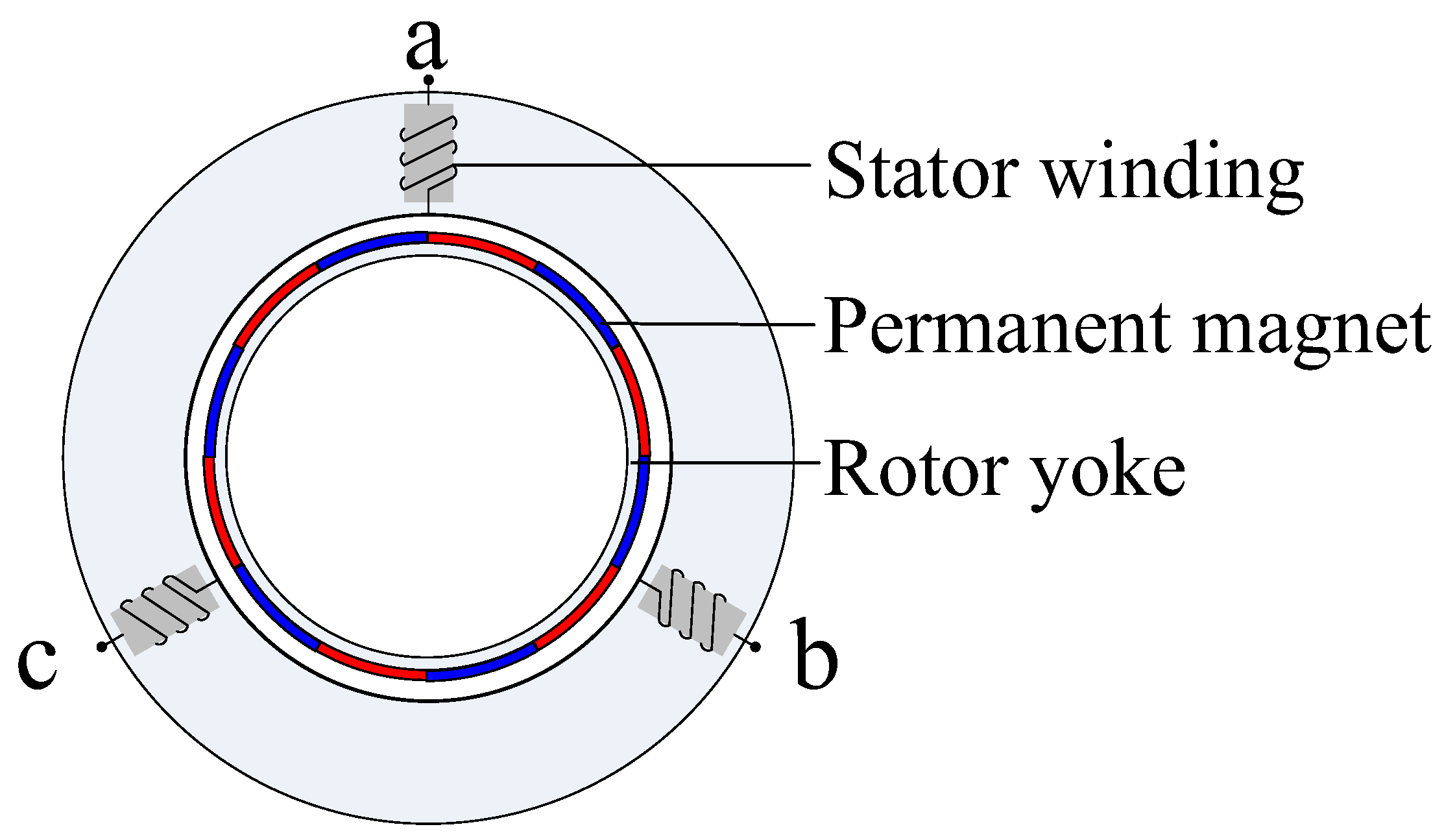
2.1. Permanent Magnet Synchronous Motor (PMSM)

As shown in Figure 2, the rotor of the PMSM consists only of permanent magnets and silicon steel sheets, which presents a simple structure and high reliability. Thanks to the utilization of high-performance permanent magnets, it has obvious advantages in terms of power density, torque density and efficiency [16]; therefore, the PMSM is a good choice as a propulsion motor, and it has been applied in many AEA/MEA.
Airbus and Rolls-Royce have collaborated to develop the E-Fan X, the world’s largest hybrid electric aircraft, which is based on the BAe 146 RJ100, replacing one of the four engines with a 2 MW PMSM; the E-Fan X has now passed wind tunnel testing [23]. The X-57 is a NASA demonstration model for distributed propulsion technology and electric aircraft technology, with two 60 kW PM motors on both sides of the wings for the cruise phase and twelve 10.5 kW motors for the climb phase; it has completed ground tests and is about to enter the test flight phase [24,25]. Siemens developed a 260 kW PM motor for the Extra 330LE aerobatic aircraft. The lightweight propulsion system helped the Extra 330LE set a world record for the shortest climb time [26].
However, there are still some shortcomings in the fault tolerance capability of traditional PMSMs. First, the performance of permanent magnets is affected by temperature, and the high temperature brought by short-time overload may lead to irreversible demagnetization of permanent magnets; thus, it is necessary to carry out reasonable enhancement of the thermal isolation capability of the motor to ensure the stable operation capability of the motor under a high-temperature environment [27]. In addition, when a short-circuit fault occurs in the motor, even if the power supply is stopped, due to inertia, the rotor and the main magnetic field of permanent magnets will still be in high-speed rotation, which in turn leads to induced voltage as well as winding current in the windings. Therefore, PMSMs need to further introduce fault-tolerant design to meet the requirements of a propulsion motor based on increased power density.

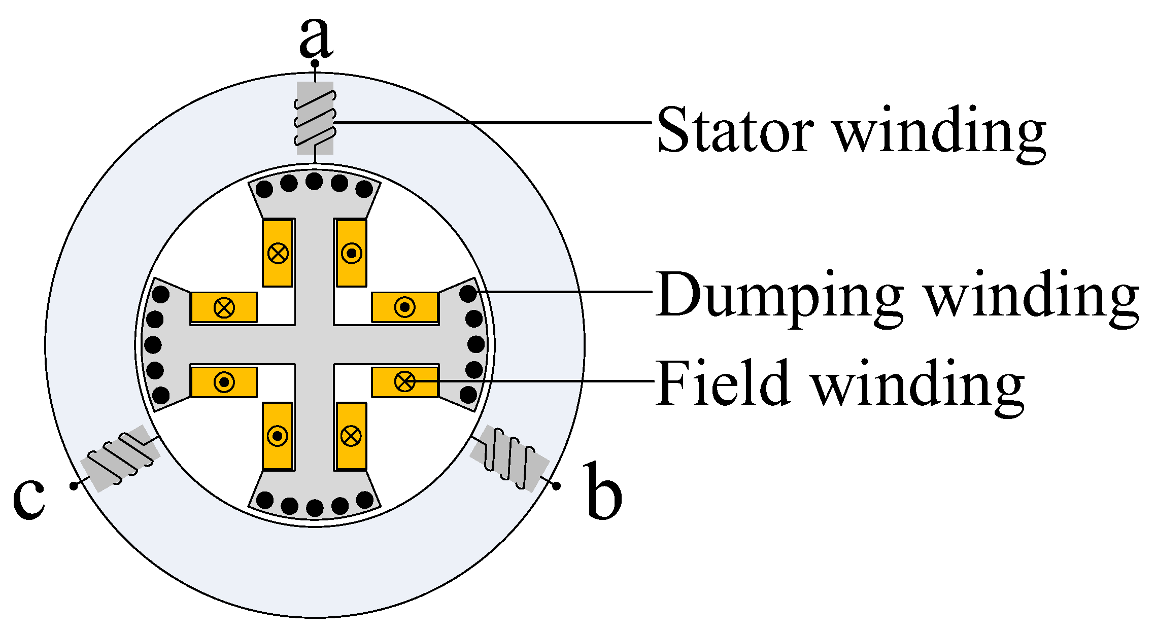
2.2. Wound-Field Synchronous Motor (WFSM)

As shown in Figure 3, the main magnetic field is established by passing DC current into the excitation winding. The advantage of this structure is that the strength of the main magnetic field can be changed by controlling the magnitude of the DC current in the excitation winding, making it more controllable. In case of a short-circuit fault, the main magnetic field can be cut off directly to avoid the short-circuit current; however, considering the performance of ferromagnetic materials and excitation winding losses, the power density and efficiency level of WFSMs are hardly comparable to those of PMSMs.
In the aspect of power density, which is the most concerning aspect of propulsion motors, the 19,000 rpm, 1 MW WFSM developed by Honeywell is the limit of such motors at the current level, with a power density of 7.9 kW/kg [28]. However, there is still a gap with PMSMs, so the application of such motors in the field of propulsion motors is limited. On the other hand, due to the fully controllable magnetic field and the relatively lower cost, the aviation industry still mainly uses WFSMs as generators or starter generators; high-speed WFSMs can be directly connected to the engine, reducing mechanical losses while achieving efficient power generation and efficient use of energy. In the fully electric Boeing 787, the most electrified medium-sized airliner, the engine and gearbox are replaced with an integrated power generation structure consisting of the engine and two MW-class WFSMs, which provide electrical power to the entire aircraft; Furthermore, similar power generation structures can be found in the Boeing 777, Boeing 747-X, Airbus 340 and Airbus 380 [28].

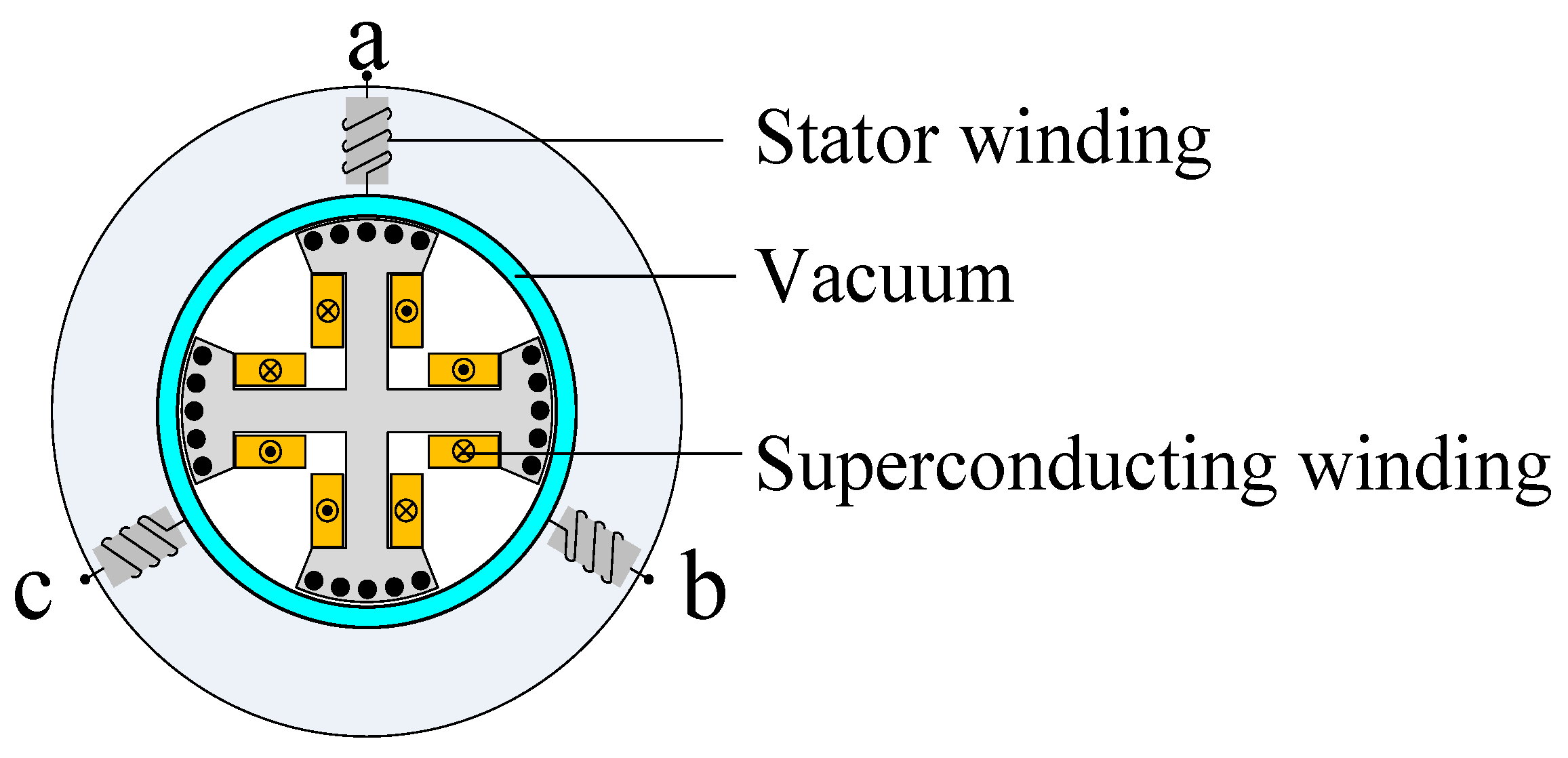
2.3. High-Temperature Superconducting Motor (HTSM)

As shown in Figure 4, an HTSM is formed by replacing the excitation winding with a superconducting coil on the basis of a WFSM. Thanks to the property of superconducting materials having zero resistance under certain conditions, the loss of the excitation coil is negligible, so the magnetic load of the motor can be increased by using a very large excitation current, which results in a significant increase in both power density and efficiency. In terms of output capability, HTSMs are clearly the preferred choice for future AEA/MEA propulsion motors. According to the analysis, the power density of HTSMs with a fully superconducting structure can reach 16 kW/kg, while superconducting motors with superconducting excitation can reach 7 kW/kg, which shows that superconducting motors have outstanding advantages in terms of power density [29].
NASA has high expectations for high-power HTSM electric propulsion technology, and in its leading high-efficiency megawatt motor research project, the design target is set at 1.4 MW output power, 99% efficiency and a high power density of 16 kW/kg. For higher application to electric propulsion systems, the motor uses a standard aircraft cooling system, at the optimal turbomachinery speed (6800 rpm) direct drive, and has a certain fail-safe capability due to the electrically excited structure; there are numerous research results showing the efficacy of the current project [30]. In addition, in NASA’s lead AEA N3-X, in order to take full advantage of the high power density of HTSMs, 14 sets of HTSMs of 1.785 MW are used for distributed propulsion, with the power density of each motor exceeding 10 kW/kg; at the same time, two sets of HTSMs of 25 MW are used for the work of power generation. The aircraft is expected to be put into service in 2040 [31].
However, at this stage of the technology, there are still technical barriers to the application of HTSMs in electric propulsion systems. First, the implementation of superconducting windings requires a suitable cryogenic environment, i.e., the introduction of cryogenic equipment in the motor system, which will lead to significant increases in the complexity, weight and cost of the propulsion system. Also, the addition of new structures increases the possibility of motor system failures, which presents limits in terms of safety and reliability [32].

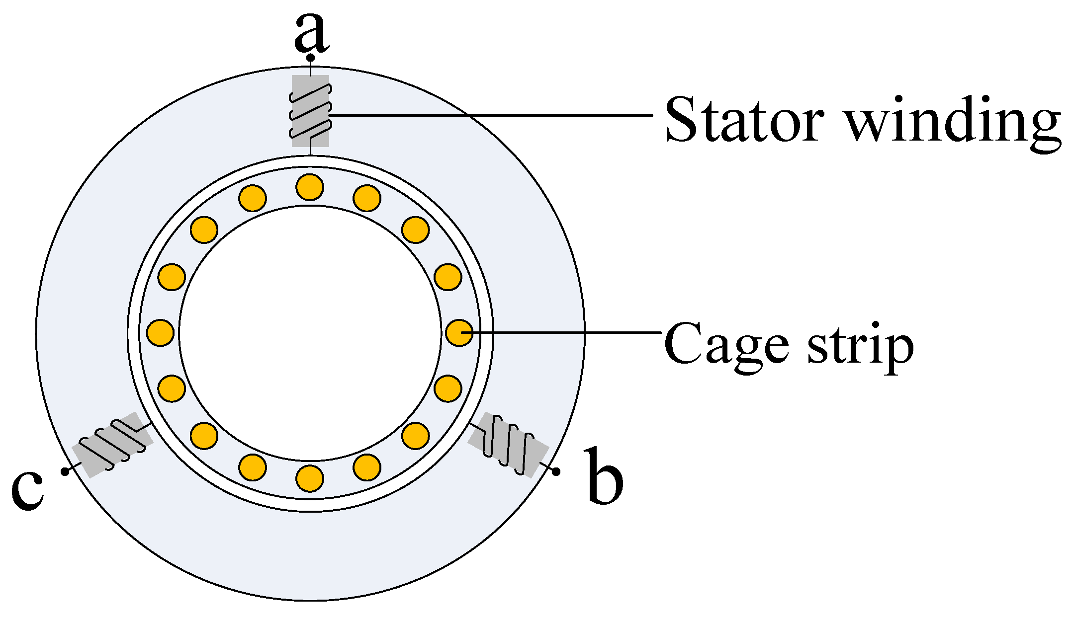
2.4. Induction Motor (IM)

As shown in Figure 5, the IM rotor is generally a guide bar or winding. Thanks to its simple structure and robustness, as well as the relatively early start to its development process, IM has a mature design and production process, and the corresponding control technology is well-developed and cost-efficient. In addition, its controllability characteristics lead to it being often used in the field of servo control [33]. On the other hand, part of the armature current of IM is used to establish the main magnetic field, so it has no advantage in terms of power factor, efficiency and power density [34].
IMs are also suitable for use in high-speed power generation applications due to their strong high-speed operation as well as weak magnetic capability. The University of Wisconsin–Madison has been investigating the use of squirrel-cage IMs for high-speed power generation for more than a decade in a NASA-funded aerospace isolated starter–generator project [35]. The authors of [36] summarize the characteristics, advantages and development lineage of IM-based generator systems in the last two decades and indicates that cage IMs are a competitive candidate for current starter–generator systems due to their simplicity, robustness, low cost, ease of maintenance, and high overload capability. In addition, some researchers have attempted to apply induction motors to electric propulsion systems, and Ohio State University, in a NASA-funded MW-class induction motor design project, is currently designing a 2.6 MW induction motor with a power density of 13 kW/kg [37]. Thanks to the strong servo capability, Ref. [38] presents a steady-state and dynamic model of an AC induction motor drive and typical aircraft fuel system piping components, using induction motor closed-loop control to effectively reduce transient pressure surges during sudden valve closures and the resultant flow overshoot.

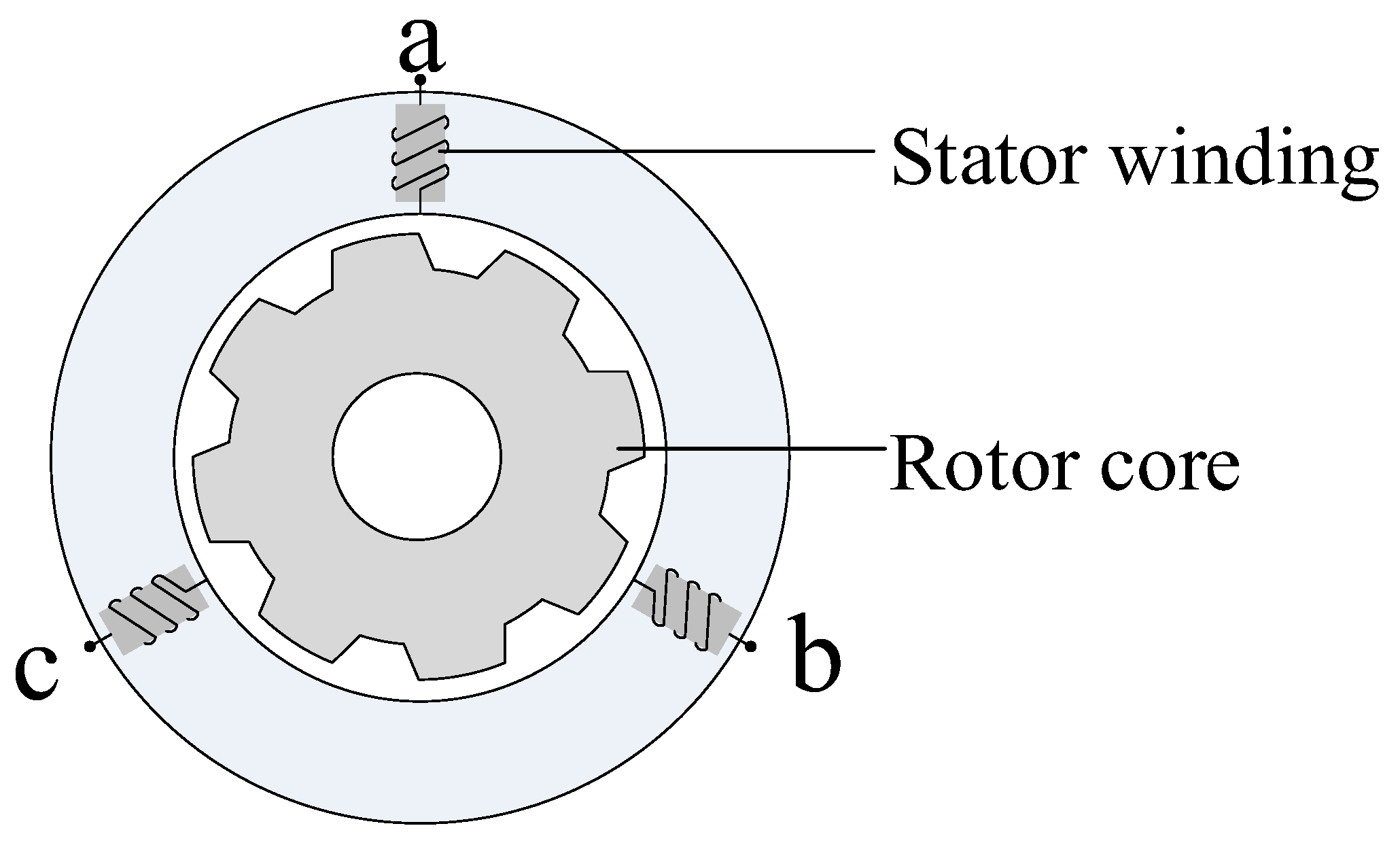
2.5. Switched Reluctance Motor (SRM)

As shown in Figure 6, the rotor of the SRM is a whole, laminated, silicon steel sheet, without windings or permanent magnets. This structure enables the rotor to withstand high thermal and mechanical stresses, so it is suitable for high-temperature and high-speed conditions and other harsh elements [39]; on the other hand, similar to IMs, the main magnetic field of the motor is established entirely by the stator current, and there is no induction potential in the windings after the power supply is stopped after a fault [40]. However, this excitation method also results in higher eddy current losses and a lower power factor, so the power density of this motor is lower, and the volume of the SRM is 50% larger than that of the PMSM with the same output power. In addition, there is an inherent torque fluctuation problem in SRMs, and the torque fluctuation and vibration noise during operation are not negligible. Therefore, application in the field of electric propulsion is limited [41].
Due to the simple structure, robustness, wide speed range and relatively low power density of switched reluctance motors, they are often used as starters in military and aerospace applications. At the beginning of this century, Lockheed Martin used switched reluctance motors for the F-22 fighter jet [10]. Further, this company’s single-engine military aircraft, the F-35, also uses a dual-channel switched reluctance motor [42].
In order to further improve the power density and operating efficiency of switched reluctance motors, synchronous reluctance motors (SynRMs), which combine the characteristics of synchronous motors, have emerged. Their rotor consists of silicon steel sheets with smooth outer edges and a series of regular magnetic barriers inside; the stator side is similar to that of WFSMs, which are also driven and controlled by converters [43]. The reluctance torque is the main component of the torque of this motor; thus, optimizing the structure of the magnetic barrier and increasing salient rate are the main research elements in the design of this type of motor [44].
Further, the introduction of permanent magnets into the magnetic barrier of synchronous reluctance motors to create permanent-magnet-assisted synchronous reluctance motors is a research hotspot, with the aim of enhancing the power density of this type of reluctance motor and to reduce the inherent torque fluctuation [45]. Nevertheless, compared with permanent magnet synchronous motors, the power density of permanent-magnet-assisted switched reluctance motors is still low, making it difficult to meet the requirements of aircraft propulsion motors; at the same time, the more complicated rotor structure and the more difficult installation method of permanent magnets have hindered further application in the field of aircraft propulsion motors. Thanks to the reasonable application of permanent magnet torque and reluctance torque motors, their structure is mainly used in the current development of motors with fewer rare-earth elements for electric vehicles [46].
During the development of AEA/MEA, in order to meet the special and severe operating conditions, the main focus of propulsion system design is the performance of motors in terms of power density, reliability, robustness, drive performance, thermal management and cost; the performance of the above five motor types in these areas is summarized in Figure 7.
Combining Figure 7 and the previous analysis, it can be seen that PMSMs and HTSMs have outstanding advantages in power density; however, the complex structure of HTSMs leads to higher cost and lower reliability, which makes it difficult to meet the requirements of high safety for propulsion motors. WFSMs, SRMs and IMs have higher reliability, and the controllable main magnetic field makes them stronger in controllability and fault tolerance; however, because the armature current is partly used to generate the magnetic field, the efficiency and power density of the propulsion motor are limited, affecting the aircraft load. Therefore, compared with the other four types of motors, the PMSM has a more balanced performance in all aspects and has a lot of room for development; thus, it is the most suitable type of propulsion motor in the transition from traditional aircraft to electrification at this stage. Based on above analysis, in order to better meet the demanding requirements of AEA/MEA propulsion motors, many scholars around the world have proposed a series of optimization schemes based on PMSMs and garnered promising results. In the following section, the optimization methods and typical cases in recent years in terms of power density improvement and fault tolerance performance improvement of PMSM propulsion motors will be summarized and analyzed.

3. High-Power-Density Design

In general, the dimensional and electromagnetic parameters of permanent magnet motors satisfy the following relationship [47]:
D 2 l e f n P = 6.1 × 10 3 α p K N m K d p A B δ
where D denotes the stator inner diameter, lef denotes the axial length, n denotes the rated speed, P′ denotes the calculated power, αp denotes the polar arc coefficient, KNm denotes the distribution coefficient, Kdp denotes the winding coefficient, A denotes electrical load, and Bδ denotes the magnetic load.
D 2 l e f can represent the motor volume, so a transformation of the above equation yields an expression for the motor power density, ρ P , as follows:
ρ P = P D 2 l e f = α p   K N m K d p n A B δ 6.1 × 10 3
From Equation (2), it can be seen that in order to enhance the power density of a permanent magnet motor, the following aspects can be addressed:
  • Boosting the electromagnetic load;
  • Boosting the rotational speed;
  • Boosting the output power.
In addition, on the basis of optimizing the body structure from a global perspective, to improve the power density of the entire propulsion system, including the drive control and heat dissipation structure, this integrated design is also an important development direction in the process of improving the power density of electric propulsion systems.

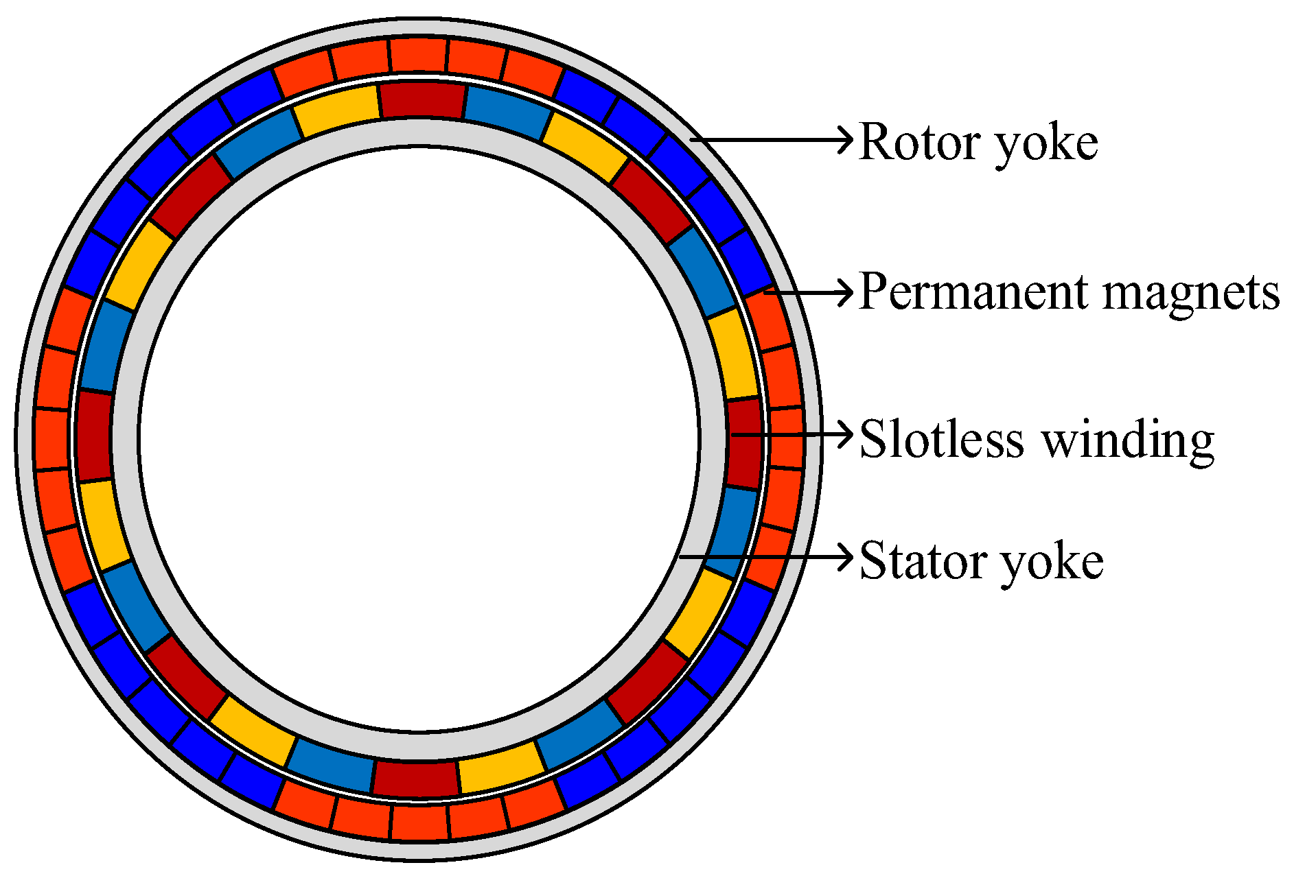
3.1. High Electromagnetic Load

The improvement of the magnetic loading of PMSMs includes the improvement of air-gap magnetism in terms of fundamental wave amplitude and sinusoidal degree, which is mainly done by optimizing the shape of permanent magnets, the magnetizing method and the arrangement method. Among them, the Halbach array has become the most commonly used method to improve the air-gap magnetism of PMSMs by virtue of its simple structure and obvious optimization effect; it is widely used in high-power-density PM motors at present. As shown in Figure 8, the Halbach array is a permanent magnet structure formed by alternately arranging parallel and angularly magnetized permanent magnets, and the magnetization direction of the permanent magnets varies with the array at a fixed angle. Its main features are as follows [48].
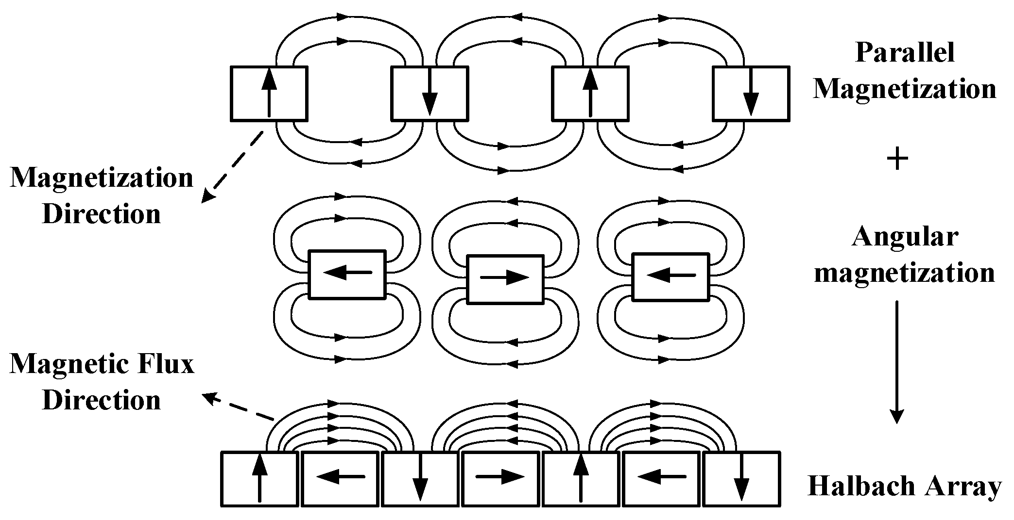
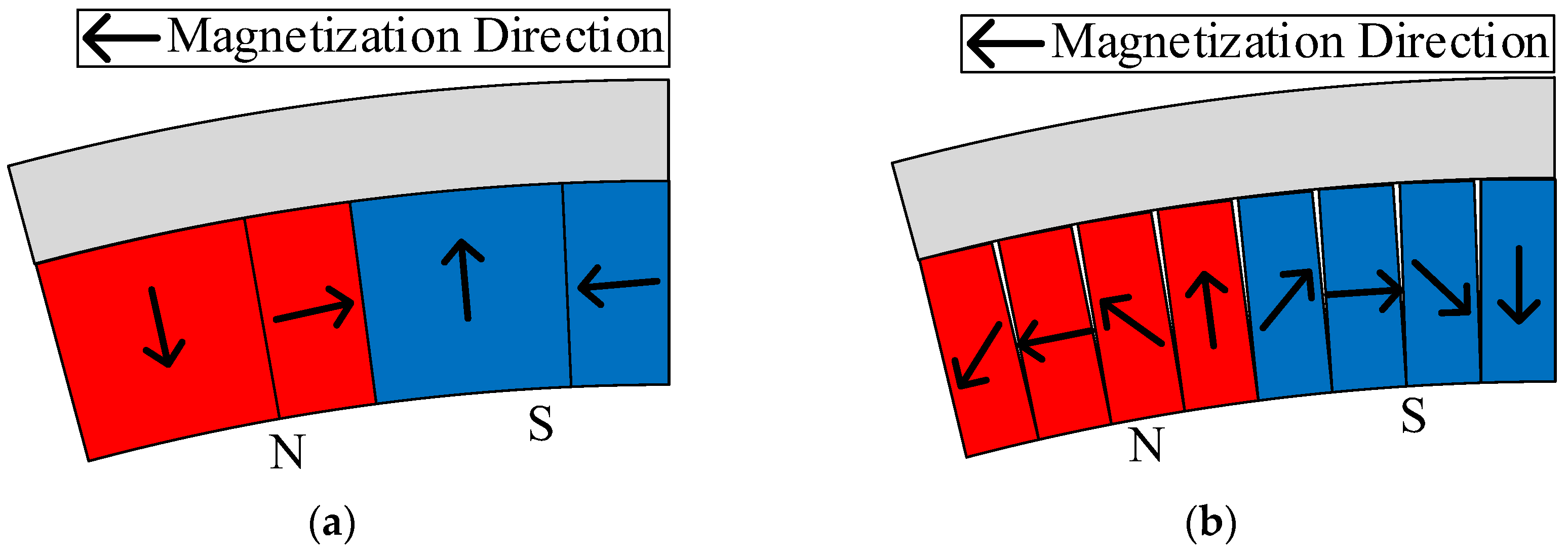
  • Single-sided magnetization characteristics: increase the air-gap magnetic density while weakening the rotor yoke magnetic density, ideally removing the rotor yoke and effectively reducing the weight of the motor.
  • Improve the sinusoidality of the air-gap density: improve the sinusoidality of the counter potential and reduce torque pulsation and harmonic loss.
  • Improve the fundamental amplitude of the air-gap density: higher output torque and power under the same electrical load.
The selection of the number of pole segments is an important research point in the application of Halbach arrays. In an external rotor PMSM designed by the University of Nottingham for a green gliding system [49], it was found in the analysis of the number of pole segments that if the simpler two-segment design (also known as a quasi-Halbach array) as shown in Figure 9a is used, the mutually perpendicular magnetization angle leads to the two adjacent permanent magnets having a certain degree of localized demagnetization, which affects the quality of the air-gap magnetic density on the one hand, and may bring irreversible demagnetization problems to the permanent magnets on the other. The study found that increasing the number of magnet chunks and decreasing the magnetization angle between neighboring poles can be an effective solution to this problem. Finally, in the four-segment Halbach array design, as shown in Figure 9b, the angle of the neighboring poles of the magnetization direction is 45 degrees, the impact of the neighboring permanent magnet is smaller, and the optimization effect is obvious.
The interaction between the permanent magnets and the ferromagnetic material of the stator teeth is known as the cogging torque, and this inherent torque can lead to torque fluctuations during motor operation, which in turn can create vibration and noise problems that may affect the smooth operation of the aircraft when used as a propulsion motor. In order to achieve smoother propulsion, eliminating the stator teeth and adopting a slotless structure is a suitable optimization method [50,51,52,53].
However, the absence of the stator slot core will lead to an increase in the equivalent air-gap length with significant leakage, and the air-gap magnetic density amplitude and sinusoidality are greatly affected, which can be offset to a certain extent by using the single-sided magnetization characteristics of Halbach arrays. In Ref. [51], a slotless PMSM propulsion motor was designed as shown in Figure 10, and the number of pole segments was quantitatively analyzed based on the analytical model of the Halbach array air-gap magnetic field; a five-segment design was finally chosen. Since the motor itself is slotless, the analytical model fits well with the finite element model; with the Halbach array, the air-gap magnetic density reaches 1.2 T, based on which, the motor achieves a power density of 10 kW/kg.
Following this idea, Ref. [52] further discarded the stator–rotor yoke core and designed an ironless PMSM for the electric propulsion system of a small aircraft. Compared with conventional motors, the motor retains only the Halbach permanent magnet array and centralized windings, as shown in Figure 11a, while the ferromagnetic material is replaced by 3D-printed material, resulting in a low weight; the physical structure is shown in Figure 11b. The motor has an output of 600 W and weighs only 0.9 kg. Although the torque and power density of this motor are not high, the study verifies the feasibility of the ironless motor and provides an idea for further lightweighting of PMSM propulsion motors.
In terms of electrical load enhancement, the main focus is on the redesign of the winding form, and the hairpin winding is one of the current research hotspots in this field. Hairpin windings, with a high slot-filling rate, short manufacturing time, short winding ends, high voltage protection capability and other advantages, are attracting more and more attention and research in the field of current high-performance permanent magnet propulsion motors. As shown in Figure 12a, which details the installation position of coils composed of common circular wires in the stator slot, the circular structure leads to the inability to closely fit between the wires; thus, the slot-filling rate of this form of winding is generally not more than 75% [54]. As shown in Figure 12b, with its rectangular structure and higher fit to the stator slots, the hairpin winding can achieve a slot fullness of up to 85%, which will effectively increase the power density of the motor under the same current density [55]. In addition, because each layer of the hairpin winding is whole, its winding cross-sectional area is larger, the phase resistance is smaller, and the efficiency is higher under low-speed and large-torque working conditions; compared with the general circular winding, the efficiency can be increased by 2%, and the overload point can realize about 10% efficiency improvement [56].
Compared with general round wire motors, thanks to the more mature manufacturing and installation process, the end structure of hairpin winding motors is more compact, so the end extension length is much smaller than that of the round wire motors. This effectively reduces the length of the end, and the result of this improvement is that the DC resistance can be lowered by 30–40% [57]. In order to further reduce the end projection length, the Denso Corporation of Japan proposed to change the common triangular end of the hairpin winding into a stepped shape, and the outermost part of the winding can be presented in a horizontal state, as shown in Figure 13, which results in a further compact structure of the end of the hairpin winding, and the end extension length is even smaller [58].
Also, more regularly shaped hairpin windings are more conducive to the design of the heat dissipation structure, which further increases the limit of the motor power density [59]. The University of Nottingham, in a study on oil injection cooling of hairpin windings, stated that the hairpin winding consists of multiple precisely placed stator bars (or pins), and that this precise conductor arrangement and the gaps between the end windings combine perfectly with injection cooling, a cooling arrangement that strikes the right balance between high heat flux removal, fluid stocking, robustness and assembly complexity. It has been experimentally proven that the hairpin windings can withstand current densities of 14 A/mm2 under water-cooling conditions, and up to 23 A/mm2 using the oil injection cooling structure shown in Figure 14.
Since each wire of the hairpin winding is a solid conductor as shown in Figure 15a, its eddy current loss will be significantly increased when the frequency is high, and with the increase of rotational speed this part of the loss will gradually occupy the main position of the loss [60]. Therefore, in the application of the hairpin winding, the choice of conductor material and the modeling analysis and weakening of AC loss are research hotspots. In Ref. [61], conductor eddy current loss is studied. Using finite elements as shown in Figure 15b, the winding domain was divided into individual conductors to evaluate the AC losses in each turn. In addition, copper and aluminum were compared at different frequency levels. The results show that in addition to weight and cost savings, aluminum has better electromagnetic properties, especially in the high frequency range, where the electromagnetic properties of aluminum conductors are much better.
In addition, the current limitation of the application of hairpin windings is mainly due to the difficulty of material manufacturing and processing as well as the effective control of cost; its manufacturing steps are shown in Figure 16. How to realize the automatic production of materials and control the quality of welding in the connection process is the key to determine the performance of hairpin windings [62].

3.2. High Speed

The high-speed design of PMSMs is an effective way to improve their power density and presents the following main advantages [63,64]:
  • Much smaller size than low- and medium-speed motors at the same output power;
  • Low rotational inertia and high dynamic response capability;
  • Direct drive of the load, eliminating the need for traditional mechanical gearing, improving mechanical reliability and reducing transmission noise.
In PMSMs, the current frequency increases with the motor speed, thus making the core losses significantly higher; the use of a slotless design is considered a way to solve this problem. In Ref. [64], a 1 MW external rotor high-speed PMSM was designed with a speed of up to 18,000 rpm, as shown in Figure 17. The motor adopts a slotless design on the stator side to completely eliminate the tooth losses, and on the rotor side, a Halbach array design is used to eliminate the rotor yoke by using its unilateral magnetizing ability to further eliminate the rotor core losses. Therefore, the motor retains only the ferromagnetic material in the stator yoke, which greatly reduces the core loss and also effectively controls the overall weight of the motor. With this design, the core loss of the motor is only 1.5 kW, which is about 0.15% of the output power; based on this, the motor has a power density of 14 kW/kg.
For surface-mounted PM motors, permanent magnets are mounted on the outer (inner) circle of the rotor, making it easier to optimize the permanent magnet structure. However, during high-speed operation, the surface-mounted permanent magnets may separate from the rotor yoke, so a tension sleeve must be installed outside the permanent magnets to affix them; the introduction of this structure brings problems such as increased air-gap length, reduced air-gap magnetic density and higher motor weight, which can be circumvented by using an embedded rotor. A 250 kW, 15,000 rpm embedded high-speed PMSM propulsion motor was designed in [65]. As shown in Figure 18a, the permanent magnets are magnetized by a tangential phase and embedded in the rotor core ring in the form of spokes; the thickness of the upper and lower bridges of the permanent magnets is adjusted to ensure that the rotor core strength meets the requirements of high speed. However, the bridges can result in significant rotor leakage, which seriously affects the quality of the air-gap magnetic field. For this reason, the rotor yoke of this motor uses a duplex ferromagnetic material to correct the rotor magnetic circuit. This material has the property of being magnetically conductive in one direction and non-permeable in the perpendicular direction. The magnetic bridge uses the nonpermeable phase, and the rest of the magnetic bridge remains in the permeable phase, resulting in the corrected magnetic circuit shown in Figure 18b. As can be seen, the magnetic leakage phenomenon is well controlled, and the air-gap magnetic field optimization is obvious; thus, the output torque of this motor is significantly improved, and the power density can reach 16.6 kW/kg.
Axial flux is also often used in high-speed designs. In Ref. [53], a 250 kW axial flux external rotor high-speed permanent magnet propulsion motor was designed with a rated speed of 15,000 rpm, as shown in Figure 19a. The stretch sleeve was mounted outside the permanent magnet ring, so the axial magnetic field was not affected, and the air-gap length could still be maintained at 1.15 mm. In addition, the motor was designed with a statorless core, as shown in Figure 19b. The stator is designed as two flat layers, fixed with epoxy resin, and completely immersed in heat dissipation oil, which has a significant heat dissipation effect. With this design, the motor can operate stably at high speed and high current, with a power density of 13 kW/kg.

3.3. High Power

In the NASA Blue Book on the development plan for AEA/MEA propulsion motors, it is stated that for safe and stable manned flight of electric aircraft, propulsion motors must achieve at least MW-class output power and a power density of 16 kW/kg [16]. Figure 20 summarizes the relationship between motor power and power density for some applications of AEA/MEA propulsion. It can be seen that as the motor output power increases, its power density generally shows an upward trend, and the MW-class propulsion motor power generally reaches 10 kW/kg or more. It can be seen that high power is the main development trend of AEA/MEA propulsion motors in the future.
As can be seen from the previous analysis, to meet high-power and high-power-density targets, the motor size of PMSMs must be kept as compact as possible, while increasing the electromagnetic load and speed. This will lead to a more complex electromagnetic environment and thermal environment within the motor. The motor, materials, processes and heat dissipation design are complex elements, and a variety of factors must be considered for comprehensive design; the future of high-power and high-power-density propulsion motor design will gradually converge on multi-physical field coupling design and systematic integrated design [15].

3.4. High Integration Degree

The power density improvement should not be limited to the motor body but should be done at the level of the whole motor system. Generally, the motor system consists of the motor body, inverter, driver, cables, housing, bearings, shaft, heat dissipation structure and related fastening parts [66]. Among them, there are cable connections between the driver and the inverter and between the inverter and the motor. Excessively long and heavy cables not only enhance the complexity of the propulsion system and make the system less reliable but also increase the weight of the propulsion system and reduce the aircraft load capacity. Therefore, in order to reduce the influence of cables, it is necessary to adopt an integrated design—integrating the driver, inverter and motor body—to achieve compactness and light weight at the system level [67,68].
The integrated design of the motor system refers to the “triple integration” of the driver, inverter and motor body, eliminating the connection cables between each part, the housing of the driver and inverter, and the DC bus. The whole system shares a common heat dissipation structure, resulting in a more compact system structure and better space utilization. The integrated design has several advantages as follows:
  • Reduction of system volume: about 10–20%;
  • Reduction of manufacturing costs: about 30–40%;
  • Improving system power density;
  • Improving system electromagnetic compatibility;
  • Improving system efficiency;
  • Improve high-temperature operation capability.
The authors of [68] summarize the feasible solutions for the integrated structure of the motor system, as shown in Figure 21. In order to achieve the maximum utilization of space, it is more feasible and more common to mount the drive structure on the outer circle or end of the stator housing.
Based on [64], in order to further improve the power density and fault tolerance of the propulsion system, Ref. [69] proposed an integrated structure for this motor, as shown in Figure 22. Due to the modular design of the motor body with 6 × 3 phases, the motor body is embedded in a cooling jacket with a positive hexagonal outer edge. Further, the power devices of each set of three-phase windings and their control boards are placed on the corresponding sides of the positive hexagon, i.e., each side controls one unit motor. An integrated design of the drive control structure, fault tolerance and heat dissipation structure is achieved.
The thermal environment of the integrated motor system is more compact. Compared with the motor body, the power devices are more sensitive to temperature, and excessive temperature will affect their stability and increase the switching losses; thus, a reasonable thermal design is a problem that must be solved after the motor system is integrated. The authors of [70] designed a five-phase integrated motor with SiC devices and a control board integrated at the end of the stator winding, as shown in Figure 23, both of which share a water-cooled structure for heat dissipation. In order to analyze the heat dissipation capability, a detailed thermal resistance network was established, and the heat dissipation capability was adjusted by adjusting the cross-sectional area of the water channel and the number of spiral turns of the water channel. A proper heat dissipation effect was achieved at all operating points to meet the requirements of the power devices and the drive for the operating environment temperature.

4. Fault-Tolerant Design

In addition to optimizing the power density of the electric propulsion system, safety and reliability improvements are also factors that must be considered in the process of flight electrification; thus, the fault-tolerant design of PMSMs is very important. In general, the fault-tolerance process is divided into two main stages [71]:
(1)
Fail-safe phase: When a fault occurs, the motor system is able to cut off the fault in time and inhibit the spread of the fault so as to reduce the impact of the faulty parts on the healthy parts.
(2)
Fault-tolerant operation stage: This ensures that the motor system still has partial or full output capability after a failure, thus maintaining the safe operation of the propulsion system.
In order to ensure the above two phases, the isolation of various physical quantities between the phases of the motor must be achieved, mainly including electrical isolation, magnetic isolation, mechanical isolation, thermal isolation, etc. [72]. This reduces the probability of the occurrence of faults inside the motor and the impact of faults relative to other healthy phases, i.e., achieving inter-phase decoupling. Several teams have conducted in-depth research on fault-tolerant technology for PMSMs from multiple angles and levels, with research objectives focused on the following:
(1)
Redundant design: Redundant phase windings, winding units, stator and rotor, and even the whole motor are set up to cut off the faulty part when a fault occurs, and a certain fault-tolerant algorithm is used to keep the healthy part working so as to maintain the safe operation of the motor.
(2)
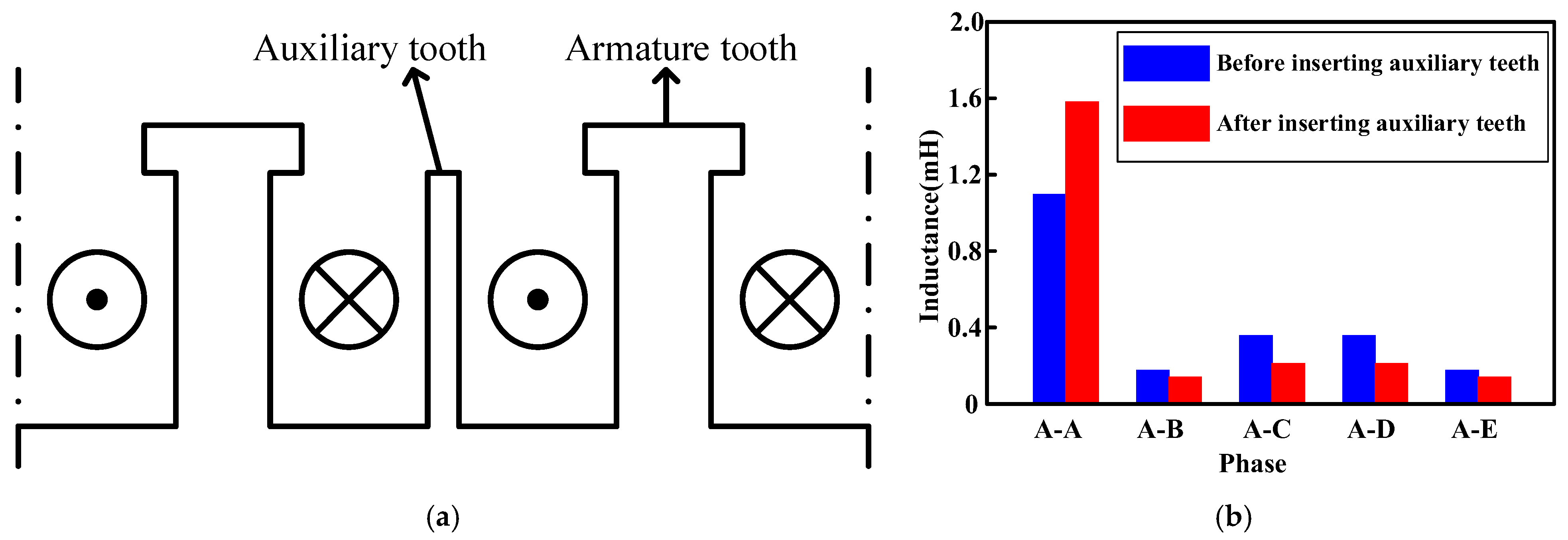
Fault-tolerant design: The winding form and stator teeth are optimized to improve the self-inductance and reduce the mutual inductance, so as to limit the short-circuit current and prevent the spread of short-circuit faults.

4.1. Redundant Design

4.1.1. Multi-Phase Motors

The traditional three-phase motor is limited by the number of supply phases; when one phase winding failure will not be able to synthesize a stable rotating magnetic field, thus bringing great fluctuations to the output torque, the motor will lose the ability to output stable torque. With the rapid development of power electronics technology and the continuous improvement of related material performance, multi-phase inverter drive technology has gradually matured, and the multi-phase motor, with its excellent fault tolerance, has received more and more attention and research. Compared with the traditional three-phase motor, the multi-phase motor has the following main characteristics [73]:
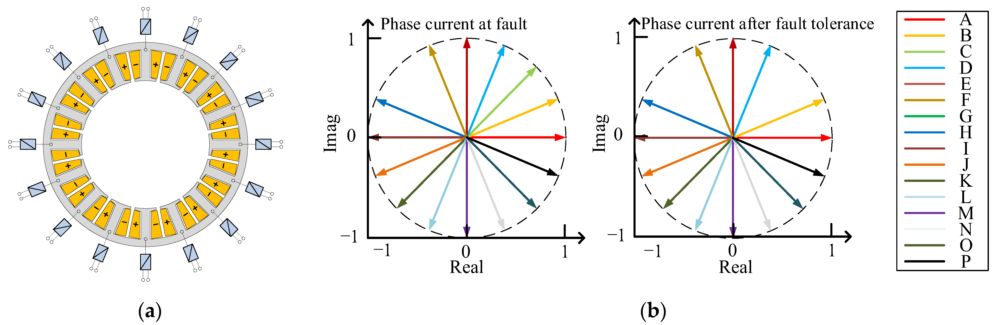
  • High fault tolerance performance: When a fault occurs in phase m (m ≤ (N-3)) of the N-phase motor, only the power supply to that phase needs to be cut off; then, the corresponding fault-tolerant operation algorithm is used to adjust the amplitude and phase of the healthy 0 phase winding current to reconstruct the circular rotating magnetic field, thus ensuring safe operation of the motor.
  • Low-voltage and high-power operation: Under a certain output power and rated current, the rated voltage of the motor decreases with the number of phases, which has obvious advantages in applications where the voltage level is limited.
  • High degree of control freedom: The phase voltage is often used as the control object in motor control. Thus, the increase in the number of phases will result in the control volume growing geometrically; the degree of control freedom is significantly increased, so there is more room for algorithm design.
The study in [74] compares the performance of 3-phase and 6-phase motors with the same design parameters. As shown in Figure 24a,b, the stator–rotor structure is identical, the three-phase motor is in the form of a single layer winding with an even number of conductors per slot, and the six-phase motor has a double layer winding with the same number of conductors per slot as the three-phase motor, in which case they are able to maintain identical weights. The analysis compares the losses in the rated condition and the short-time overload condition, and the results show that the six-phase motor can obtain lower losses in both conditions, and more significantly in the overload condition, i.e., the six-phase motor operates more efficiently. The is because the six-phase motor reduces the saturation level of the stator and rotor, which allows the motor to obtain higher overload capacity.
The analysis provided in [75] compares the output performance and fault tolerance of a three-phase motor with a five-phase motor for the same dimensional parameters, with both using a single-layer winding structure to ensure a strong magnetic isolation capability, as shown in Figure 25. The finite element analysis found that the five-phase structure leads to smoother output torque of the motor, with lower torque fluctuations in the open-circuit or short-circuit state of one phase; on the other hand, the five-phase design also allows higher freedom in the body and drive design, a more flexible design, and greater suitability for working with a high degree of reliability.
However, although the fault-tolerant performance of the motor gradually increases with the number of phases, the structure, control complexity, and cost of the motor drive subsequently rise, so the number of phases in a multi-phase motor generally does not exceed six [76].

4.1.2. N×3-Phase Design

Although the multi-phase design has obvious advantages in terms of fault-tolerant control performance, it also leads to a significant increase in the difficulty and complexity of motor mathematical modeling and control algorithm design. The simpler N×3-phase motor (also known as the multi-unit three-phase motor) has become another excellent choice in the field of fault tolerance. Its stator winding consists of N neutral unconnected three-phase windings, each of which occupies 1/N of the stator circumference, and each three-phase unit is powered by an independent drive controller, thus achieving effective electrical and magnetic isolation between the units. In terms of control, since each motor unit is still a three-phase structure, the traditional three-phase motor control algorithm and circuit design experience and principles are still applicable, which greatly reduces the design complexity. In terms of fault-tolerant operation, the high redundancy makes the fault-tolerant operation of the motor very simple: when one phase fails, only the power supply to the motor of the unit in which the phase is located needs to be cut off, and the healthy unit can maintain the motor torque and speed without using fault-tolerant algorithms [77].
The authors of [77] detail the design method of modular motors and the principle of unit motor division: if a motor has a pole-slot combination of p-pole and s-slot, and the maximum common factor of p and s is n, the number of unit motors into which the motor can be divided is n 0 , and each unit motor has a pole-slot combination of p 0 -pole and s 0 -slot, with
n = n 0 = g c d ( p , s )
p 0 = p n 0
s 0 = s n 0
Further, the study analyzes the fault-tolerant performance of an N×3-phase motor using a 30-pole, 72-slot motor as an example. According to the division criteria, this motor can be divided into three 10-pole 24-slot three-phase unit motors, i.e., 3 × 3-phase. Firstly, the study analyzes the armature magnetic inductance line distribution in the fault state, as seen in Figure 26a,b; the armature magnetic field of the unit motor is almost coupled to itself only, and the coupling degree between it and the neighboring unit motor is very low, which proves that each unit motor has strong independence, and the healthy unit motor is almost unaffected by the fault one(s). At the torque output level, it can be seen from Figure 26c that when the winding phase current is certain, the average output torque is proportional to the number of running units, and the torque fluctuation is almost unaffected by the number of running units, which further indicates that the coupling degree between the unit motors is very low and has a strong fault-tolerant output capability.
It can be seen that the prerequisite for achieving high fault tolerance in N×3-phase motors is the effective isolation between each unit motor, so it is necessary to analyze the magnetic coupling phenomenon between unit motors. In Ref. [78], the inductance matrix is calculated by finite element analysis, and it is found that with this structure, the mutual inductance between the windings inside the unit and the inductance between the units is not as high as the inductance matrix. The mathematical model of the magnetic chain of a single unit in an N×3-phase motor is shown in Equation (6).
λ x a λ x b λ x c = L + L s l k M + M s l k M M + M s l k L + L s l k M + M s l k M M + M s l k L + L s l k i x a i x b i x c + λ x , c c a λ x , c c b λ x , c c c + λ x , p m a λ x , p m b λ x , p m c = L + L s l k M + M s l k M + M s l k M + M s l k L + L s l k M + M s l k M + M s l k M + M s l k L + L s l k i x a i x b i x c + 0 0 M s l k 0 0 0 M s l k 0 0 i x a i x b i x c + λ x , c c a λ x , c c b λ x , c c c + λ x , p m a λ x , p m b λ x , p m c
where M s l k represents the unbalanced value of the winding mutual inductance inside the unit, and λ x , c c b represents the coupled magnetic chain between units.
From the mathematical model, only an even number of modules operating together can cancel each other out; when one of the modules is cut off by a fault, the unbalanced inductance will cause a negative sequence current as well as torque fluctuations at two times the frequency.
Further, Ref. [79] designed a 4×3-phase motor with a single-layer winding structure and no interconnection of the internal stator windings, with 24 lead-in windings outside the end cap. The stator windings are not connected to each other, and the 24 leads are divided into four groups of three-phase windings outside the end cover, as shown in Figure 27. After finite element analysis, the coupling between the coils in this structure is only 4%. In the fault state, due to the presence of unbalanced inductance, the current of the healthy phase will be significantly uneven, with higher current in spaces close to the faulty winding and lower current at a distance. Based on this, the temperature increase of different modules after the fault will be different, putting some pressure on the heat dissipation of the motor. This further shows that in the design of N×3-phase motors, attention should be paid to enhancing the motor self-inductance and reducing the coil intermittent coupling.
Further, on the basis of the stator using N×3 phases or being multi-phase, the modular design of the motor can be realized. In Ref. [80], the authors showed that for a six-phase motor modular design, each phase of the winding corresponding to the stator and the drive circuit can be manufactured separately, to achieve physical decoupling between the phases; the various parts can be put together to obtain a complete motor stator, as shown in Figure 28. By this kind of structure, on the one hand, it is more efficient in production and manufacturing; on the other hand, in the faulty state, the faulty parts can be replaced directly, which improves the maintenance efficiency and reduces the maintenance cost.

4.1.3. Open-Winding Structure

Limited by the cost and the size of the driver, the motor drive circuit often adopts a half-bridge structure, while the stator winding is connected in a star shape, so the phase current must meet the limit of 0 neutral current. In order to further improve the fault tolerance, it is a feasible idea to adopt an open-winding design for the drive circuit. The study in [81] uses an open-winding structure in a five-phase motor, as shown in Figure 29. Each phase is driven by an H-bridge circuit, where the inter-phase current constraints disappear, maximizing phase-to-phase electric isolation; each phase can be driven by a separate drive control circuit, which allows higher responsiveness to fault conditions. Thanks to this, the motor is fault-tolerant in the event of a three-phase fault.
In order to make fuller use of the advantages of open-winding multi-phase motors in fault-tolerant operation, Ref. [82] designed a 16-slot, 12-pole PMSM, as shown in Figure 30a. The stator of this motor has a double-layer centralized winding structure, where the coils on each tooth are wound independently. Each coil is connected to an independent inverter, and the current amplitude and phase of each coil are controlled separately, so that the number of phases is equal to the number of teeth as well as the number of slots of this motor. Thanks to the high degree of freedom, the study proposes fault-tolerant control by cutting off the power supply to the corresponding number of coils when a breakage fault occurs during operation, as shown in Figure 30b. It can be seen that when a breakage fault occurs in phase G, the power supply to phase C is cut off accordingly, at which time the remaining phase current still has symmetry, and no further fault-tolerant control is required to make the motor output stable torque.

4.2. Design to Enhance Fault Tolerance

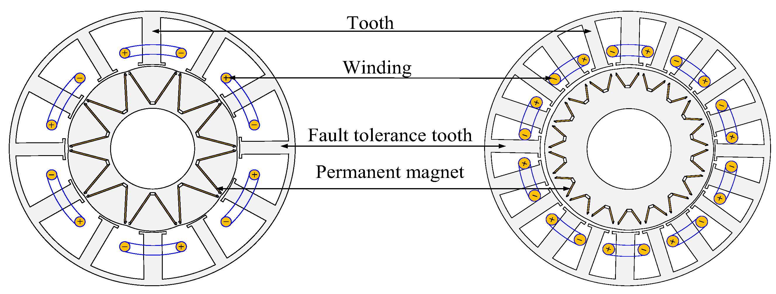
4.2.1. Enhanced Magnetic Isolation Capability

From the previous analysis, it is clear that regardless of the winding structure, the magnetic isolation capability between phases or units is a crucial indicator to ensure the fault-tolerant performance of the motor, and the optimization of the winding form and stator structure is often used in PMSMs to weaken the magnetic coupling.
The authors of [83] analyzed the difference in magnetic isolation capability between single- and double-layer concentrated windings and found that the single-layer winding structure has the lower mutual inductance for a certain motor size, while the coupling phenomenon between different phases of the double-layer winding structure is relatively obvious. However, in order to achieve large torque and high power density, the propulsion motor generally adopts a flat structure with a relatively large length and diameter; thus, the single-layer winding will have the problems of long ends and large stator copper losses and can lead to more serious spatial harmonics, which may cause a decrease in the sinusoidal degree of the counter-electromotive force, higher core losses, and increased eddy current losses in the permanent magnet. Therefore, this motor still adopts a double-layer winding and takes two-step measures to weaken the magnetic coupling, as shown in Figure 31a. First, holes are opened above the slots, which contain different phases as magnetic barriers; then, the tooth tips of those slots are eliminated, and an open slot is used. The armature magnetic induction line distribution cloud is shown in Figure 31b. It can be seen that the armature magnetic field only cross-chains with itself after adopting this measure, which effectively reduces the coupling between different phases.
The study in [84] combined the respective advantages of single- and double-layer concentrated windings and proposed a single- and double-layer hybrid winding, as shown in Figure 32a, where the middle slot is a double-layer concentrated winding slot, and the sides are single-layer concentrated winding slots. Using finite element analysis of the distribution of magnetic inductance lines in one phase, as shown in Figure 32b, it can be seen that the armature magnetic field in one phase is almost not coupled with other phases; thus, this winding form has obvious advantages for enhancing magnetic isolation capability, and the inductance parameters under the three winding forms are shown in Table 1. It can be seen that with the single–double-layer hybrid winding structure, the mutual inductance is controlled very effectively and is almost negligible, despite the fact that the self-inductance is reduced with respect to the single layer.
For the single–double-layer hybrid winding, in order to improve the slot utilization rate, Ref. [85] adopted the method of offsetting the stator teeth on both sides of the double-layer slot, as shown in Figure 33, to reduce the single-layer winding slot area and increase the double-layer winding slot area; at the same time, in order to limit the slot width, the stator tooth shoe width on both sides of the double-layer slot is increased, and by optimizing the offset angle and the tooth shoe width, the stator size parameters that can simultaneously satisfy the winding slot full rate, high self-inductance and low mutual inductance are obtained.
For the N×3-phase motor, in order to minimize the coupling phenomenon between unit electrics, Ref. [86] proposed a kind of large- and small-span winding; when the slot contains windings from different three-phase units, the winding is changed to a large-span form and coupled with its own unit motor, as shown in Figure 34. This avoids the overlapping of windings between different unit motors, and at the same time realizes the electrolytic coupling as well as the mechanical decoupling between unit motors, which effectively improves the isolation capability between unit motors.
The authors of [87] propose removing one coil from each of the three phases of each unit motor in the N×3-phase motor, as shown in Figure 35. On the one hand, this winding structure results in no overlapping coils between different unit motors and achieves electric coupling as well as mechanical decoupling between unit motors; on the other hand, the unwound teeth can be used as fault-tolerant teeth to provide access to the armature magnetic field, further enhancing the degree of magnetic decoupling and reducing mutual inductance. At the same time, due to the high number of stator slots in the N×3-phase motor, the impact on the output capacity after removing the coils is minimal, and it can still meet the requirements for the rated index.
The unwound teeth in the stator teeth are called “fault-tolerant teeth”, and their main function is to provide a path for the armature magnetic field, to confine the armature magnetic field of one phase winding to the space where the phase is located, to achieve the isolation of the inter-phase magnetic field, and to effectively reduce the inter-phase magnetic coupling. Based on this, Ref. [27] introduced auxiliary teeth in the double-layer winding structure by inserting fault-tolerant teeth between adjacent coils, as shown in Figure 36a. After finite element analysis, it was found that the mutual inductance of the motor was reduced by a maximum of 40% after the introduction of the auxiliary teeth, while the phase self-inductance was improved by 44%, as shown in Figure 36b; on the other hand, the addition of the auxiliary teeth also provided an additional thermal path, and the maximum temperature of the motor was reduced by 35%; thus, the heat dissipation capability was significantly improved.

4.2.2. Enhanced Short-Circuit Current-Limiting Capability

A short-circuit fault is one of the most dangerous faults for PMSMs. Even if the power supply to the winding is cut off, the rotor and the main magnetic field will keep rotating due to inertia, thus generating counter-electromotive force in the stator winding; on the other hand, the resistance of the short-circuit winding decreases sharply, and there will be a large short-circuit current in the short-circuit winding, generating a large amount of copper loss in a short time, which may burn up the winding in serious cases [88]. As can be seen from Equation (7), the self-inductance of the motor will play an important role in limiting the magnitude of the short-circuit current by increasing the value of motor self-inductance, which will be controlled within the range that the motor can withstand to prevent the short-circuit fault from bringing further damage to the motor.
I = E 0 R 2 + ( ω L ) 2 E 0 ω L
where E 0 is the opposite potential, R is the winding phase resistance, L is the phase inductance, and ω is the electrical angular velocity.
In addition to the winding form, the stator slot structure is also an important factor affecting the self-inductance of the motor. The study in [89] analyzes the main components of motor self-inductance and points out that slot leakage inductance accounts for the largest proportion of motor self-inductance. Further, the study calculates the analytical equation of the slot leakage inductance of the motor based on the slot diagram shown in Figure 37 and points out that in order to enhance the slot leakage inductance, the slot width can be appropriately narrowed and the slot depth can be increased; on the other hand, the enhancement of the slot leakage inductance leads to the increase of the harmonic components of the space magnetomotive force, which results in the increase of the antipotential harmonic content, torque fluctuation, and iron core losses. The narrow slots may also pose difficulties in the winding, so it is necessary to balance the needs of each aspect in the actual design.
In addition to the optimization of the body structure, the introduction of an external device for short-circuit current suppression is a feasible approach. In Ref. [90], a ferrite ring is introduced at the winding end, which is wrapped around the auxiliary winding beforehand and then installed together with the ring at the winding end, as shown in Figure 38a. Then, the stator coil, ferrite ring and auxiliary winding together form the transformer structure, as shown in Figure 38b. When a short-circuit fault occurs in the winding, resulting in a sudden increase in current, the transformer releases the energy through the drain resistor, thus effectively reducing the short-circuit current.

5. Conclusions and Outlook

This paper analyzes and summarizes the latest achievements in the research of AEA/MEA propulsion motors, summarizes the main research directions of the high-power-density and fault-tolerant design of PMSMs, highlights the classical design schemes, analyzes the advantages and disadvantages of various schemes and the corresponding optimization methods, and draws conclusions and outlooks as follows.
Propulsion motors, as the core devices in the process of aircraft electrification, have received extensive attention and research in recent years. The main hotspots include the selection of motor topologies, the realization of high power density and the design of high fault tolerance.
In the analysis of the basic principle, structure and application status of common motor types in AEA/MEA, it is found that the PMSM has become the most suitable choice of propulsion motor in the development of AEA/MEA due to the advantages of simple structure, high power density and reliability. Adopting a series of methods to further improve the power density as well as fault-tolerant performance is the main research direction in the current development of PMSMs.
In order to meet the demand for high power density in propulsion motors for AEA/MEA, the design of propulsion motors and their systems generally shows a trend of strong electromagnetic load, high power, high speed, and integration through optimizing the form of permanent magnets, the stator structure, the motor topology, the winding method and the selection of more suitable materials. Thus, the motor system can output higher speed and torque in a more compact internal environment. On the other hand, the increase of power density is accompanied by the testing of material performance, structural strength, heat dissipation capability and manufacturing processes; thus, multi-physical field coupling design and multi-objective optimization design will be the future of propulsion motor design, including comprehensive consideration of different performance indicators for iterative design, to ensure the balance between different design indicators.
In order to meet the demand of AEA/MEA for propulsion motor safety and reliability, the propulsion motor and its system show the trend of high redundancy, multi-module design and strong isolation in fault-tolerant design. By optimizing the winding form, stator structure, slot type, etc., the inter-phase coupling is minimized, and the independence between phases/units is maximized to ensure the motor has fault safety and fault-tolerant operation. At the same time, strong fault tolerance is inevitably accompanied by a rise in the number of power devices and the size of the drive, and the increase in leakage inductance will to some extent lead to a decline in the output performance of the motor itself. Thus, in fault-tolerant design, reliability and output capability need to be considered comprehensively.

Funding

This research was funded by National Natural Science Foundation of China grant number 52122704 and U2141224.

Conflicts of Interest

The authors declare no conflict of interest.

References

  1. Xiangwan, D.; Zhou, D.; Chao, Q.; Wen, Z.; Huhe, T.; Liu, Q. The Concept of Low-Carbon Development. In Overview of Low-Carbon Development; Springer: Singapore, 2019. [Google Scholar]
  2. Cheng, J.; Shuxiao, L.; Zheng, W.; Zhanhong, C. The Characteristic Differences between Ecological Culture and Low-carbon Tourism Cognition under the Vision of Carbon Neutrality. J. Resour. Ecol. 2022, 13, 936–945. [Google Scholar]
  3. Air Transport Action Group—Facts and Figures. Available online: https://www.atag.org/facts-figures.html (accessed on 17 September 2020).
  4. Milos, L.; Giangrande, P.; Hebala, A.; Nuzzo, S.; Galea, M. Review, Challenges, and Future Developments of Electric Taxiing Systems. IEEE Trans. Transp. Electrif. 2019, 5, 1441–1457. [Google Scholar]
  5. Ashkan, B.; Ghassemi, M. Components of Electrical Power Systems in More and All-Electric Aircraft: A Review. IEEE Trans. Transp. Electrif. 2022, 8, 4037–4053. [Google Scholar]
  6. Hall, D.L.; Chin, J.C.; Anderson, A.D.; Thompson, J.T.; Smith, A.D.; Edwards, R.; Duffy, K.P. Development of a Maxwell X-57 High Lift Motor Reference Design. In Proceedings of the 2019 AIAA/IEEE Electric Aircraft Technologies Symposium (EATS), Indianapolis, IN, USA, 19–22 August 2019; pp. 1–24. [Google Scholar]
  7. Whurr, J.R.; Hart, J. A Rolls-Royce Perspective on Concepts and Technologies for Future Green Propulsion Systems; Wiley: Hoboken, NJ, USA, 2015. [Google Scholar]
  8. Lin, Y.W. The Development and Challenges of More Electric Aircraft. In Highlights in Science, Engineering and Technology; Darcy & Roy Press: Hillsboro, OR, USA, 2022. [Google Scholar]
  9. Shuli, W.; Zhang, S.; Ma, S. An Energy Efficiency Optimization Method for Fixed Pitch Propeller Electric Aircraft Propulsion Systems. IEEE Access 2019, 7, 159986–159993. [Google Scholar]
  10. Kristiansen, N.J.; Leandro, M.; Suul, J.A.; Molinas, M. High-Power Machines and Starter-Generator Topologies for More Electric Aircraft: A Technology Outlook. IEEE Access 2020, 8, 130104–130123. [Google Scholar]
  11. William, W.P.; Sirimanna, T.S.; Bozhko, S.V.; Haran, K.S. Electric/Hybrid-Electric Aircraft Propulsion Systems. Proc. IEEE 2021, 109, 1115–1127. [Google Scholar]
  12. Ralph, J.; Bowman, C.L.; Jankovsky, A.L.; Dyson, R.W.; Felder, J.L. Overview of NASA Electrified Aircraft Propulsion Research for Large Subsonic Transports. In Proceedings of the 53rd AIAA/SAE/ASEE Joint Propulsion Conference, Atlanta, GA, USA, 10–12 July 2017. [Google Scholar]
  13. Commercial Aircraft Propulsion and Energy Systems Research: Reducing Global Carbon Emissions; National Academies Press: Washington, DC, USA, 2017.
  14. Christopher, C.; Hansman, R.J. Safety Considerations in Emerging Electric Aircraft Architectures. In Proceedings of the 2018 Aviation Technology, Integration, and Operations Conference, Atlanta, GA, USA, 25–29 June 2018. [Google Scholar]
  15. Ehab, S.; Abdalmagid, M.; Pietrini, G.; Sa’adeh, N.-M.; Callegaro, A.D.; Goldstein, C.; Emadi, A. Review of Electric Machines in More-/Hybrid-/Turbo-Electric Aircraft. IEEE Trans. Transp. Electrif. 2021, 7, 2976–3005. [Google Scholar]
  16. El-Refaie, A.M.; Osama, M. High specific power electrical machines: A system perspective. In Proceedings of the 2017 20th International Conference on Electrical Machines and Systems (ICEMS), Sydney, Australia, 11–14 August 2017; pp. 1–6. [Google Scholar]
  17. Xiaolong, Z.; Bowman, C.L.; O’Connell, T.C.; Haran, K.S. Large electric machines for aircraft electric propulsion. IET Electr. Power Appl. 2018, 12, 767–779. [Google Scholar]
  18. Nagel, N.J. Actuation Challenges in the More Electric Aircraft: Overcoming Hurdles in the Electrification of Actuation Systems. IEEE Electrif. Mag. 2017, 5, 38–45. [Google Scholar] [CrossRef]
  19. Wenping, C.; Mecrow, B.C.; Atkinson, G.J.; Bennett, J.W.; Atkinson, D.J. Overview of Electric Motor Technologies Used for More Electric Aircraft (MEA). IEEE Trans. Ind. Electron. 2012, 59, 3523–3531. [Google Scholar] [CrossRef]
  20. Hebala, A.; Nuzzo, S.; Connor, P.H.; Gerada, C.; Galea, M. On the Fault Tolerance and PM Demagnetisation of a High-Performance Aircraft Propulsion Motor. In Proceedings of the 2022 International Conference on Electrical Machines (ICEM), Valencia, Spain, 5–8 September 2022; pp. 2338–2343. [Google Scholar]
  21. Dexter, J.; Brown, G.V. Power Requirements Determined for High-Power-Density Electric Motors for Electric Aircraft Propulsion; NASA: New York, NY, USA, 2005.
  22. Aldo, B.; Cavagnino, A.; Tenconi, A.; Vaschetto, S.; di Torino, P. The safety critical electric machines and drives in the more electric aircraft: A survey. In Proceedings of the 2009 35th Annual Conference of IEEE Industrial Electronics, Porto, Portugal, 3–5 November 2009; pp. 2587–2594. [Google Scholar]
  23. Airbus. The E-Fan X Puts Its Aerodynamic Design to the Test. Available online: https://www.airbus.com/en/newsroom/stories/2020-02-the-e-fan-x-puts-its-aerodynamic-design-to-the-test (accessed on 4 February 2020).
  24. Clarke, S.; Redifer, M.; Papathakis, K.; Samuel, A.; Foster, T. X-57 power and command system design. In Proceedings of the 2017 IEEE Transportation Electrification Conference and Expo (ITEC), Chicago, IL, USA, 22–24 June 2017; pp. 393–400. [Google Scholar] [CrossRef]
  25. Marrufo, M.A.; Kloesel, K.J. X-57 70kW Permanent Magnet Synchronous Cruise Motor Finite Element Electromagnetic Modeling. 2019. Available online: https://ntrs.nasa.gov/api/citations/20190033258/downloads/20190033258.pdf (accessed on 17 September 2023).
  26. Hallez, R.F.; Colanaeli, C.; Cuenca, J.; De Ryck, L. Impact of Electric Propulsion on Aircraft Noise—All-Electric Light Aircrafts Case Study. In Proceedings of the 2018 AIAA/IEEE Electric Aircraft Technologies Symposium (EATS), Cincinnati, OH, USA, 12–14 July 2018; pp. 1–17. [Google Scholar]
  27. Shu-Mei, C.; Sun, P.; Kuang, Z.; Zhao, T. A thermal-electromagnetic coupled motor design flow for electric aircraft propeller drive application. In Proceedings of the 2017 IEEE Transportation Electrification Conference and Expo, Asia-Pacific (ITEC Asia-Pacific), Harbin, China, 7–10 August 2017; pp. 1–6. [Google Scholar]
  28. Anghel, C. Modeling and Simulation of a Power Generation System with a High Power Generator; SAE International: Warrendale, PA, USA, 2013. [Google Scholar]
  29. Sivasubramaniam, H.K.; Kalsi, S.S.; Arndt, T.; Karmaker, H.; Badcock, R.A.; Buckley, B.B.; Haugan, T.J.; Izumi, M.; Loder, D.; Bray, J.; et al. High power density superconducting rotating machines—Development status and technology roadmap. Supercond. Sci. Technol. 2017, 30, 123002. [Google Scholar]
  30. High-Efficiency Megawatt Motor (HEMM). Available online: https://www1.grc.nasa.gov/aeronautics/eap/technology/hemm/ (accessed on 20 December 2022).
  31. Mona, G.; Barzkar, A.; Saghafi, M.H. All-Electric NASA N3-X Aircraft Electric Power Systems. IEEE Trans. Transp. Electrif. 2022, 8, 4091–4104. [Google Scholar]
  32. Dong, T.; Gao, Y.; Nakamura, T. High Fault-Tolerance Dual-Rotor Synchronous Machine with Hybrid Excitation Field Generated by Halbach Permanent Magnets and High Temperature Superconducting Magnets. IEEE Trans. Appl. Supercond. 2023, 33, 5202105. [Google Scholar] [CrossRef]
  33. Benzaquen, J.; He, J.; Mirafzal, B. Toward more electric powertrains in aircraft: Technical challenges and advancements. CES Trans. Electr. Mach. Syst. 2021, 5, 177–193. [Google Scholar] [CrossRef]
  34. van der Geest, M.; Polinder, H.; Ferreira, J.A.; Zeilstra, D. Machine selection and initial design of an aerospace starter/generator. In Proceedings of the 2013 International Electric Machines & Drives Conference, Chicago, IL, USA, 12–15 May 2013; pp. 196–203. [Google Scholar]
  35. Elbuluk, M.E.; Kankam, M.D. Potential starter/generator technology for future aerospace application. IEEE Aerosp. Electron. Syst. Mag. 1996, 11, 17–24. [Google Scholar] [CrossRef]
  36. Feifei, B.; Liu, H.; Huang, W.; Hu, Y.; Degano, M.; Gerada, C.; Rajashekara, K. Induction-Machine-Based Starter/Generator Systems: Techniques, Developments, and Advances. IEEE Ind. Electron. Mag. 2020, 14, 4–19. [Google Scholar]
  37. Ohio State University Induction Machine. Available online: https://www1.grc.nasa.gov/aeronautics/eap/technology/electric-machines/induction-machine/ (accessed on 21 August 2021).
  38. Stawinski, G. Fuel Pump Motor-Drive Systems for More Electric Aircraft; ProQuest Dissertations Publishing: Ann Arbor, MI, USA, 2010. [Google Scholar]
  39. Irudaya, R.E.F.; Appadurai, M.; Rani, E.F.I.; Jenish, I. Finite-element design and analysis of switched reluctance motor for automobile applications. Multiscale Multidiscip. Model. Exp. Des. 2022, 5, 269–277. [Google Scholar]
  40. Marcin, B.; Sehab, R.; Whidborne, J.F.; Krebs, G.; Luk, P.C.-K. Fault-tolerant switched reluctance motor propulsion system for eVTOLs. J. Phys. Conf. Ser. 2023, 2526, 012065. [Google Scholar]
  41. Anderson, A.D.; Renner, N.J.; Wang, Y.; Agrawal, S.; Sirimanna, S.; Lee, D.; Banerjee, A.; Haran, K.; Starr, M.J.; Felder, J.L. System Weight Comparison of Electric Machine Topologies for Electric Aircraft Propulsion. In Proceedings of the 2018 AIAA/IEEE Electric Aircraft Technologies Symposium (EATS), Cincinnati, OH, USA, 12–14 July 2018; pp. 1–16. [Google Scholar]
  42. Ali, E.; Ehsani, M. Electrical System Architectures for Future Aircraft; SAE International: Warrendale, PA, USA, 1999. [Google Scholar]
  43. Shaopeng, W.; Zhou, J.C.; Zhang, X.; Yu, J. Design and Research on High Power Density Motor of Integrated Motor Drive System for Electric Vehicles. Energies 2022, 15, 3542. [Google Scholar]
  44. Prasad, A.I.; Toulabi, M.S.; Filizadeh, S.; Gole, A. Performance Enhancement of a SynRM and PMaSynRM Using a Cartesian Coordinates-Based Rotor Design Optimization. In Proceedings of the 2021 24th International Conference on Electrical Machines and Systems (ICEMS), Gyeongju, Republic of Korea, 31 October–3 November 2021; pp. 1429–1434. [Google Scholar]
  45. Jian-Xin, S.; Cai, S.; Hao, H.; Jin, M.-J. Comprehensive parameter design for transversally laminated synchronous reluctance machines. In Proceedings of the 2016 19th International Conference on Electrical Machines and Systems (ICEMS), Chiba, Japan, 13–16 November 2016; pp. 1–9. [Google Scholar]
  46. Wu, R.; Xu, Q.; Li, Q.; Chen, L. Reducing cogging torque and suppressing torque ripple in PMASynRM for EV/HEV applications. In Proceedings of the 2014 IEEE Conference and Expo Transportation Electrification Asia-Pacific (ITEC Asia-Pacific), Beijing, China, 31 August–3 September 2014; pp. 1–6. [Google Scholar]
  47. Bharatiraja, C.; Deepak, M.; Jagadeesh, D. Finite Element Analysis of Permanent Magnet Less Motors For Electric Vehicle Application. In Proceedings of the 2023 Fifth International Conference on Electrical, Computer and Communication Technologies (ICECCT), Erode, India, 22–24 February 2023; pp. 1–6. [Google Scholar]
  48. Masato, I.; Suto, T.; Takahashi, A.; Hara, T.; Iwano, R. Development of a High Power Density In-Wheel Motor using Halbach Array Magnets. In Proceedings of the 2022 International Conference on Electrical Machines (ICEM), Valencia, Spain, 5–8 September 2022; pp. 355–360. [Google Scholar]
  49. Michael, G.; Xu, Z.; Tighe, C.; Hamiti, T.; Gerada, C.; Pickering, S.J. Development of an aircraft wheel actuator for green taxiing. In Proceedings of the 2014 International Conference on Electrical Machines (ICEM), Berlin, Germany, 2–5 September 2014; pp. 2492–2498. [Google Scholar]
  50. Reza, I.; Alinejad-Beromi, Y.; Yaghobi, H.; Asgharpour-Alamdari, H. Design of Slotless BLDC Motor for Eliminating Cogging Torque; Scienceline: Erzurum, Turkey, 2014. [Google Scholar]
  51. Zaixin, S.; Liu, C.; Feng, K.; Zhao, H.; Yu, J. Field Prediction and Validation of a Slotless Segmented-Halbach Permanent Magnet Synchronous Machine for More Electric Aircraft. IEEE Trans. Transp. Electrif. 2020, 6, 1577–1591. [Google Scholar]
  52. Hobbs, K. Ironless, Axial Flux, Electric BLDC Motor for Aircraft Electric Propulsion. Undergraduate Thesis, University of Arkansas, Fayetteville, AR, USA, 2021. [Google Scholar]
  53. Zhuoran, Z.; Geng, W.; Liu, Y.; Wang, C. Feasibility of a new ironless-stator axial flux permanent magnet machine for aircraft electric propulsion application. CES Trans. Electr. Mach. Syst. 2019, 3, 30–38. [Google Scholar]
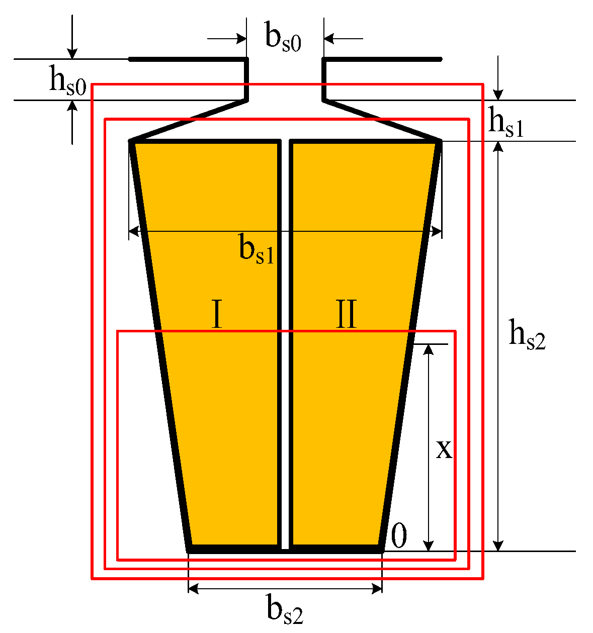
  54. Marco, V.; Zorzi, A.; Mazzucchelli, M. Torque/volume increase in Permanent Magnet Synchronous Motors by fill factor enhancement. In Proceedings of the 2018 International Symposium on Power Electronics, Electrical Drives, Automation and Motion (SPEEDAM), Amalfi, Italy, 20–22 June 2018; pp. 309–313. [Google Scholar]
  55. Tobias, G.; Seefried, J.; Franke, J. Challenges in the manufacturing of hairpin windings and application opportunities of infrared lasers for the contacting process. In Proceedings of the 2017 7th International Electric Drives Production Conference (EDPC), Würzburg, Germany, 5–6 December 2017; pp. 1–7. [Google Scholar]
  56. Shi, Y.; Ju, Y.; Yang, M. Application of Hair-Pin Winding in Low-Speed High-Torque Permanent Magnet Machines Used in Near Space. Small Spec. Electr. Mach. 2022, 50, 29–32. [Google Scholar]
  57. Faizul, M.; Rahman, K.M.; Son, Y.; Savagian, P.J.M. Electric Motor Design of General Motors’ Chevrolet Bolt Electric Vehicle. SAE Int. J. Altern. Powertrains 2016, 5, 286–293. [Google Scholar]
  58. Nimmana, R.L.S.; Chiba, A. Design of High Power Density Motor for EV Applications. In Proceedings of the 2018 21st International Conference on Electrical Machines and Systems (ICEMS), Jeju, Republic of Korea, 7–10 October 2018; pp. 104–108. [Google Scholar]
  59. Arzillo, A.; Braglia, P.; Nuzzo, S.; Barater, D.; Franceschini, G.; Gerada, D.; Gerada, C. Challenges and Future opportunities of Hairpin Technologies. In Proceedings of the 2020 IEEE 29th International Symposium on Industrial Electronics (ISIE), Delft, The Netherlands, 17–19 June 2020; pp. 277–282. [Google Scholar]
  60. Chuan, L.; Xu, Z.; Gerada, D.; Li, J.; Gerada, C.; Chong, Y.C.; Popescu, M.; Goss, J.E.; Staton, D.A.; Zhang, H. Experimental Investigation on Oil Spray Cooling with Hairpin Windings. IEEE Trans. Ind. Electron. 2020, 67, 7343–7353. [Google Scholar]
  61. Ahmed, S.; Ibrahim, M.N.F.; Sergeant, P. Mitigation of High-Frequency Eddy Current Losses in Hairpin Winding Machines. Machines 2022, 10, 328. [Google Scholar]
  62. Takashi, I.; Tanaka, Y.; Homma, H. Motor Stator with Thick Rectangular Wire Lap Winding for HEVs. IEEE Trans. Ind. Appl. 2014, 51, 2917–2923. [Google Scholar]
  63. Qiping, S.; Zhou, Z.-J.; Li, S.; Liao, X.; Wang, T.; He, X.; Zhang, J. Design and Analysis of the High-Speed Permanent Magnet Motors: A Review on the State of the Art. Machines 2022, 10, 549. [Google Scholar]
  64. Andy, Y.; Yi, X.; Martin, J.M.; Chen, Y.; Haran, K.S. A high-speed, high-frequency, air-core PM machine for aircraft application. In Proceedings of the 2016 IEEE Power and Energy Conference at Illinois (PECI), Urbana, IL, USA, 19–20 February 2016; pp. 1–4. [Google Scholar]
  65. Rasul, H.; Vahid, S.; El-Refaie, A.M. A Novel Design for a High Specific Power Interior Permanent Magnet Machine for Aerospace Applications. In Proceedings of the 2020 IEEE Energy Conversion Congress and Exposition (ECCE), Detroit, MI, USA, 11–15 October 2020; pp. 1735–1742. [Google Scholar]
  66. Mesut, U.; Keysan, O. Multi-physics design optimisation of a GaN-based integrated modular motor drive system. J. Eng. 2019, 2019, 3900–3905. [Google Scholar]
  67. Hao, C.; Wang, J.; Zhang, Z.; Zhou, L. A Review of Integrated Modular Motor Drive for Medium-Voltage Motors. In Proceedings of the 2021 IEEE 4th International Electrical and Energy Conference (CIEEC), Wuhan, China, 28–30 May 2021; pp. 1–6. [Google Scholar]
  68. Lee, W.; Li, S.; Han, D.; Sarlioglu, B.; Minav, T.A.; Pietola, M. A Review of Integrated Motor Drive and Wide-Bandgap Power Electronics for High-Performance Electro-Hydrostatic Actuators. IEEE Trans. Transp. Electrif. 2018, 4, 684–693. [Google Scholar] [CrossRef]
  69. James, A.S.; Zeng, H.; Bobba, D.; Jahns, T.M.; Sarlioglu, B. Design and Testing of a Modular High-Speed Permanent-Magnet Machine for Aerospace Propulsion. In Proceedings of the 2021 IEEE International Electric Machines & Drives Conference (IEMDC), Hartford, CT, USA, 17–20 May 2021; pp. 1–8. [Google Scholar]
  70. Shaopeng, W.; Tian, C.; Zhao, W.; Zhou, J.C.; Zhang, X. Design and Analysis of an Integrated Modular Motor Drive for More Electric Aircraft. IEEE Trans. Transp. Electrif. 2020, 6, 1412–1420. [Google Scholar]
  71. Woongkul, L.; Choi, G. A Comprehensive Review of Fault-Tolerant AC Machine Drive Topologies: Inverter, Control, and Electric Machine. In Proceedings of the 2021 IEEE 13th International Symposium on Diagnostics for Electrical Machines, Power Electronics and Drives (SDEMPED), Dallas, TX, USA, 22–25 August 2021; Volume 1, pp. 269–275. [Google Scholar]
  72. Jiaxuan, H.; Zheng, P.; Sui, Y.; Zheng, J.; Yin, Z.; Cheng, L. Third Harmonic Current Injection in Different Operating Stages of Five-Phase PMSM With Hybrid Single/Double Layer Fractional-Slot Concentrated Winding. IEEE Access 2021, 9, 15670–15685. [Google Scholar]
  73. Del Pizzo, A.; di Noia, L.P.; Di Tommaso, A.O.; Miceli, R.; Rizzo, R. Comparison between 3-ph and 6-ph PMSM drives for the electric propulsion of unmanned aerial vehicles. In Proceedings of the 2021 IEEE 15th International Conference on Compatibility, Power Electronics and Power Engineering (CPE-POWERENG), Florence, Italy, 14–16 July 2021; pp. 1–5. [Google Scholar]
  74. Li, Z.; Fan, Y.; Lorenz, R.D.; Nied, A.; Cheng, M. Design and Comparison of Three-Phase and Five-Phase FTFSCW-IPM Motor Open-End Winding Drive Systems for Electric Vehicles Applications. IEEE Trans. Veh. Technol. 2018, 67, 385–396. [Google Scholar]
  75. Tao, T.; Zhao, W.X.; Cheng, M.; Wang, Z. Review on fault-tolerant control of multi-phase machines and their key technologies. Proc. CSEE 2019, 39, 315–326. (In Chinese) [Google Scholar]
  76. Yu, W.; Chenggao, Z.; Wenjuan, H. Overview of Fault-tolerant Technologies of Permanent Magnet Brushless Machine and Its Control System. Proceeding CSEE 2022, 42, 351–372. (In Chinese) [Google Scholar]
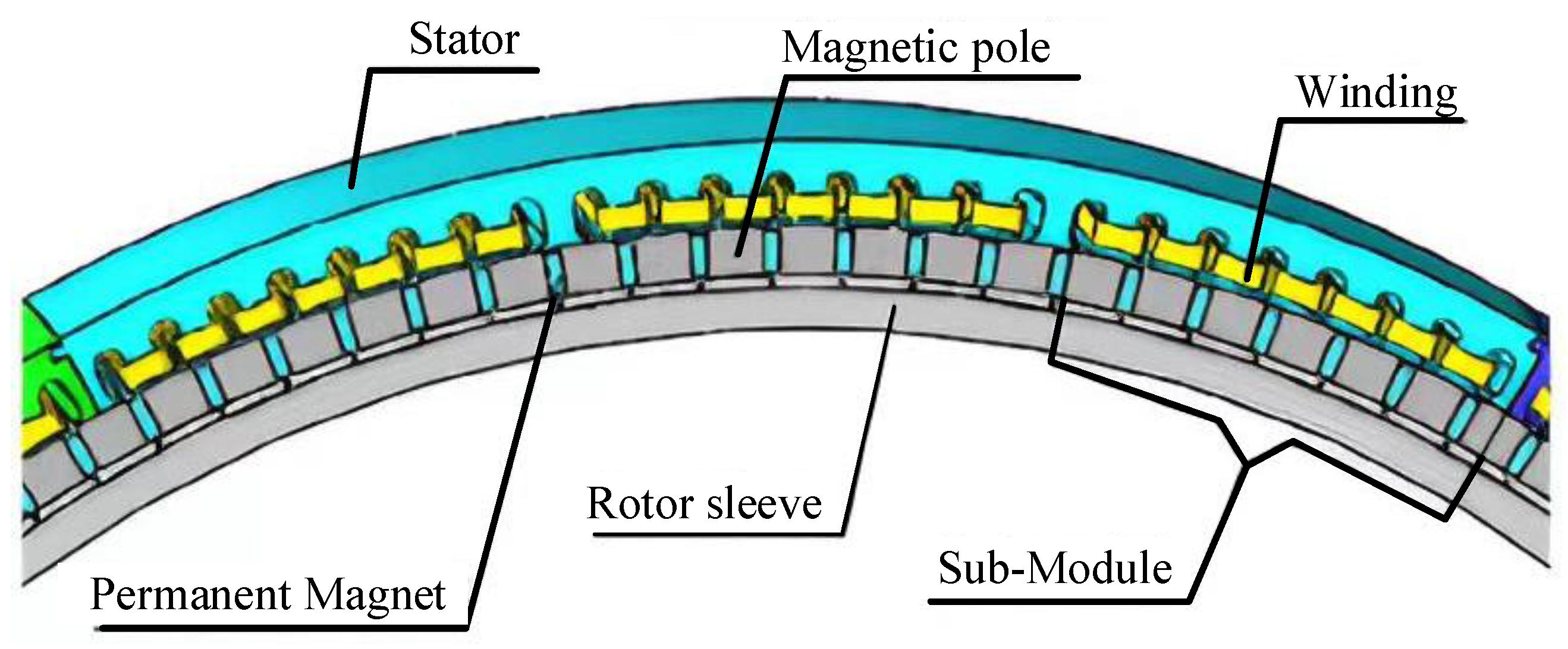
  77. Bingyi, Z.; Gan, B.; Li, Q. Analysis of a Fault-Tolerant Module-Combined Stator Permanent Magnet Synchronous Machine. IEEE Access 2020, 8, 70438–70452. [Google Scholar]
  78. Hao, Z.; Swanke, J.A.; Jahns, T.M.; Sarlioglu, B. Modular Modeling and Distributed Control of Permanent-Magnet Modular Motor Drives (MMDs) for Electric Aircraft Propulsion. In Proceedings of the 2021 IEEE Energy Conversion Congress and Exposition (ECCE), Vancouver, BC, Canada, 10–14 October 2021; pp. 4598–4605. [Google Scholar]
  79. Mellor, P.H.; Yon, J.M.; Baker, J.L.; North, D.; Booker, J.D. Electromagnetic and thermal coupling within a fault-tolerant aircraft propulsion motor. In Proceedings of the 2017 IEEE International Electric Machines and Drives Conference (IEMDC), Miami, FL, USA, 21–24 May 2017; pp. 1–7. [Google Scholar]
  80. Adam, S.; Jahns, T.M. Hardware integration for an integrated modular motor drive including distributed control. In Proceedings of the 2014 IEEE Energy Conversion Congress and Exposition (ECCE), Pittsburgh, PA, USA, 14–18 September 2014; pp. 4881–4887. [Google Scholar]
  81. Yi, S.; Zheng, P.; Yin, Z.; Wang, M.; Wang, C. Open-Circuit Fault-Tolerant Control of Five-Phase PM Machine Based on Reconfiguring Maximum Round Magnetomotive Force. IEEE Trans. Ind. Electron. 2019, 66, 48–59. [Google Scholar]
  82. Ahmed, A.W.; Mayer, J.S.; Greifelt, A.; Gerling, D. Novel Inherently Fault Tolerant Permanent Magnet Synchronous Machine (PMSM) With Multiphase Windings. In Proceedings of the 2021 24th International Conference on Electrical Machines and Systems (ICEMS), Gyeongju, Republic of Korea, 31 October–3 November 2021; pp. 42–47. [Google Scholar]
  83. Yi, S.; Yin, Z.; Cheng, L.; Zheng, P.; Tang, D.; Chen, C.; Wang, C. Multiphase Modular Fault-Tolerant Permanent-Magnet Machine with Hybrid Single/Double-Layer Fractional-Slot Concentrated Winding. IEEE Trans. Magn. 2019, 55, 1–6. [Google Scholar]
  84. Swanke, J.A.; Zeng, H.; Jahns, T.M. Modular Fault-Tolerant Machine Design with Improved Electromagnetic Isolation for Urban Air Mobility (UAM) Aircraft. In Proceedings of the 2021 IEEE Energy Conversion Congress and Exposition (ECCE), Vancouver, BC, Canada, 10–14 October 2021; pp. 4570–4577. [Google Scholar]
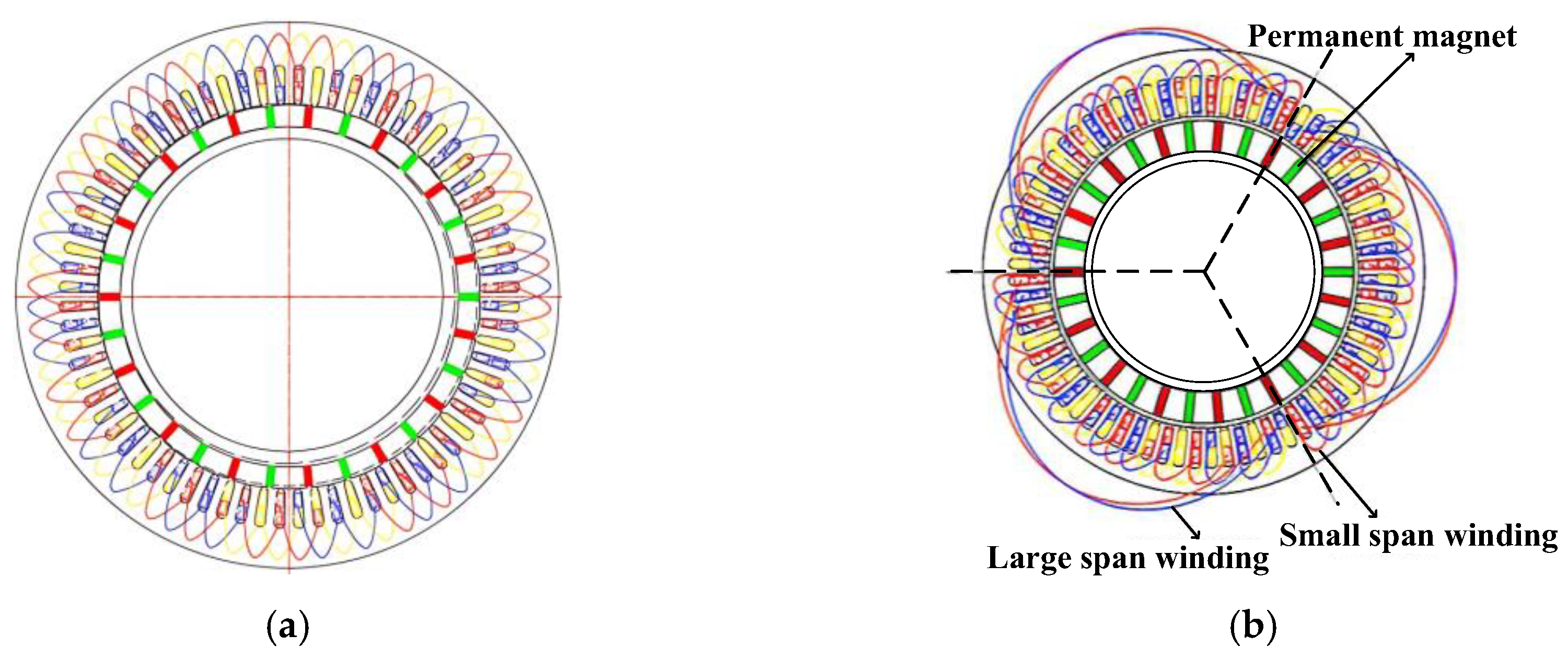
  85. Baoping, G.; Zhang, B.; Li, Q.; Guihong, F.; Li, G. Research on Operation of Low-Speed and High-Torque Module Combined Stator Permanent Magnetic Fault-Tolerant Motor with Unequal Span Winding. IEEE Access 2020, 8, 166824–166838. [Google Scholar]
  86. Zheng, R.; Wang, K.; Li, J.; Zhang, G.; Kong, J. Permanent Magnet Machine with Stator Tooth Offset to Improve Fault-Tolerant Capability. In Proceedings of the 2020 IEEE 9th International Power Electronics and Motion Control Conference (IPEMC2020-ECCE Asia), Nanjing, China, 29 November–2 December 2020; pp. 1957–1961. [Google Scholar]
  87. Yingying, X.; Zhang, B.; Feng, G. Analysis of Unwinding Stator Module Combined Permanent Magnet Synchronous Machine. IEEE Access 2020, 8, 191901–191909. [Google Scholar]
  88. Yanwu, X.; Zhang, Z.; Jiang, Y.; Huang, J.; Jiang, W. Numerical Analysis of Turn-to-Turn Short Circuit Current Mitigation for Concentrated Winding Permanent Magnet Machines with Series and Parallel Connected Windings. IEEE Trans. Ind. Electron. 2020, 67, 9101–9111. [Google Scholar]
  89. Sui, Y. Research on Key Technologies of Five-phase Fault-Tolerant Permanent-magnet Synchronous Machine for Pure Electric Vehicles. Ph.D. Dissertation, Harbin Institute of Technology, Harbin, China, 2015. [Google Scholar]
  90. Karamanis, E.K.; Kladas, A.G. Short Circuit Current reduction in PMSM by introducing End Winding Magnetic Circuits. In Proceedings of the 2020 International Conference on Electrical Machines (ICEM), Gothenburg, Sweden, 23–26 August 2020; Volume 1, pp. 332–337. [Google Scholar]
Figure 1. Propulsion motor technology.
Energies 16 07015 g001
Figure 2. Schematic diagram of the structure of the PMSM (where a,b,c denote 3-phase windings).
Energies 16 07015 g002
Figure 3. Schematic diagram of the structure of the WFSM (where a,b,c denote 3-phase windings).
Energies 16 07015 g003
Figure 4. Schematic diagram of superconducting motor structure (where a,b,c denote 3-phase windings).
Energies 16 07015 g004
Figure 5. Schematic diagram of IM (where a,b,c denote 3-phase windings).
Energies 16 07015 g005
Figure 6. Schematic diagram of SRM (where a,b,c denote 3-phase windings).
Energies 16 07015 g006
Figure 7. Performance comparison chart for five types of motor. (a) SRM; (b) IM; (c) PMSM; (d) HTSM; (e) WFSM.
Energies 16 07015 g007
Figure 8. Schematic diagram of Halbach array principle.
Energies 16 07015 g008
Figure 9. Coreless motor. (a) Quasi-Halbach arrays; (b) four-segment rectangular Halbach pole.
Energies 16 07015 g009
Figure 10. Slotless Halbach array propulsion motor.
Energies 16 07015 g010
Figure 11. Coreless motor. (a) Magnetomictic map; (b) picture of the motor.
Energies 16 07015 g011
Figure 12. Comparison of different winding forms. (a) Circular winding; (b) square winding.
Energies 16 07015 g012
Figure 13. Stepped end-windings.
Energies 16 07015 g013
Figure 14. University of Nottingham injection cooling test setup.
Energies 16 07015 g014
Figure 15. Finite element model of eddy current loss in conductors. (a) Winding distribution; (b) eddy current loss distribution.
Energies 16 07015 g015
Figure 16. Manufacturing process of hairpin windings.
Energies 16 07015 g016
Figure 17. Slotless high-speed propulsion motor.
Energies 16 07015 g017
Figure 18. Embedded high-speed PMSM. (a) Spoke-type permanent magnet; (b) magnetic circuit correction effect.
Energies 16 07015 g018
Figure 19. Axial flux high-speed motors. (a) 3D model; (b) non-iron-core stator.
Energies 16 07015 g019
Figure 20. Output power–power density curve.
Energies 16 07015 g020
Figure 21. Performance comparison chart for five types of motor. (a) Outside housing; (b) outside stator core; (c) outside end cap; (d) outside winding end.
Energies 16 07015 g021
Figure 22. MW-class integrated modular motor drive configuration.
Energies 16 07015 g022
Figure 23. 3D model of integrated motor system.
Energies 16 07015 g023
Figure 24. (a) 3-phase single-layer structure; (b) 6-phase double-layer structure, where the subscript i (i = 1,2) indicates that this phase belongs to the ith set of three-phase windings.
Energies 16 07015 g024
Figure 25. Three-phase and five-phase structures.
Energies 16 07015 g025
Figure 26. Performance during fault state: (a) one unit motor failure; (b) two unit motor failure; (c) torque output.
Energies 16 07015 g026
Figure 27. A 4 × 3-phase motor structure. (a) 3D structure; (b) winding extension.
Energies 16 07015 g027
Figure 28. Modular structure. (a) 2D model; (b) modular drive.
Energies 16 07015 g028
Figure 29. Common DC bus open-winding inverter structure.
Energies 16 07015 g029
Figure 30. Open-winding fault-tolerant motor. (a) 2D model; (b) fault tolerance strategy.
Energies 16 07015 g030
Figure 31. High-speed fault-tolerant motors. (a) 2D model; (b) weakened magnetic coupling.
Energies 16 07015 g031
Figure 32. Five-phase single- and double-layer hybrid winding. (a) 2D model; (b) magnetic susceptibility line distribution cloud map.
Energies 16 07015 g032
Figure 33. Unequal-width tooth structure.
Energies 16 07015 g033
Figure 34. Different windings. (a) Conventional winding form; (b) large- and small-span windings.
Energies 16 07015 g034
Figure 35. Non-winding winding.
Energies 16 07015 g035
Figure 36. Auxiliary fault-tolerant tooth structure. (a) Auxiliary tooth position diagram; (b) comparison of inductance parameters.
Energies 16 07015 g036
Figure 37. Slot leakage inductance analysis diagram.
Energies 16 07015 g037
Figure 38. Damping circle. (a) Round ring mounting position; (b) transformer structure.
Energies 16 07015 g038
Table 1. Inductance parameters under three winding structures.
Winding StructureLAA (mH)MAB (mH)MAC (mH)MAD (mH)MAE (mH)
Single layer3.470.040.050.050.04
Double layer2.250.020.150.150.02
Hybrid3.1400.010.010
Disclaimer/Publisher’s Note: The statements, opinions and data contained in all publications are solely those of the individual author(s) and contributor(s) and not of MDPI and/or the editor(s). MDPI and/or the editor(s) disclaim responsibility for any injury to people or property resulting from any ideas, methods, instructions or products referred to in the content.

