Abstract
The influences of V-shaped delta-wing baffles on the thermohydraulic performance characteristics in a round tube were experimentally tested. The V-shaped delta-wing baffles having a set number of wings (N = 4, 6, and 8) were comparatively tested. The V-shaped delta-wing baffles with various pitch ratios of P/D = 2.0, 2.5, and 3.0 were thoroughly fitted inside a tube. In the present work, the baffles were responsible for both the recirculation/reverse flow behind the solid baffle and the longitudinal vortex flow behind the V-shaped wing. The V-shaped winged baffles with N = 8 produced high heat transfer rates by promoting the development of reverse and vortex flows. These currents aid in fluid mixing between the two streams. Experimental results suggested that utilizing V-shaped delta-wing baffles having N = 4, 6, and 8 led to Nusselt number enhancement of up to 97–105.6%, 105.8–127.8% and 114.8–138.9%, respectively. When N was 8, the V-shaped wings baffles created additional multi vortex flows, which resulted in some fluid mixing between the vortex and the reverse flow. It was discovered that a greater turbulent intensity is imparted to the flow that was occurring between the V-shaped delta-wing baffles, which led to an increase in the rate of heat transfer when the pitch ratio was decreased. The increase in Nusselt number was up to 118.26–151.3% more than it was in a tube with the lowest pitch ratio (P/D = 2.0). It was also found that the baffles with N = 8 wings and P/D = 3.0 offered a maximum aerothermal performance factor (APF) of 1.01. Furthermore, the V-shaped delta-wing baffles have the potential for energy savings at low Re ≤ 6000, indicated by the APF beyond unity.
1. Introduction
Heat exchangers are essential parts of the thermal systems of several industries. Heat transfer enhancement techniques have been widely applied for energy savings in different systems such as refrigeration, automobiles, the process sector, and solar air heaters. Several investigations [1,2,3,4,5,6,7,8] have been carried out to minimize heat exchangers’ energy consumption and operating expenses. In the field of heat transfer engineering, turbulators, also known as vortex/reverse flow devices, are extensively utilized. Heat transfer coefficients and momentum transfer are improved by the presence of vortex flow and boundary dissipation. Vortex flow with intensive turbulent flow can enhance convection at a tube’s surface by decreasing the cross-sectional flow area and raising the velocity and temperature difference.
Conical-ring turbulators, utilized inside a tube by Yakut and Sahin, and Yakut et al. [9,10], generated turbulent flow in each ring module. As a result, the tube wall’s heat transfer rate was improved. Yaningsih et al. [11] investigated the effect of louvered strips with various louver angles on heat transfer enhancement. The results proved that the installation of louvered strips boosted heat transfer by 77% and pressure drop by 335%. The heat transfer performance characteristics of a tube mounted with circular rings with meshes were examined by Bartwal et al. [12]. The Nusselt number was promoted as the pitch length fell and the grade of metal wire net rose. Yadav and Sahu [13] evaluated the effect of helical surface discs on the heat transfer rate with various diameter ratios and helix angles. It was discovered that the heat exchanger with a diameter ratio of 0.42 had the highest heat transfer rate. It is notable that all aerothermal performance factors of the enhanced devices were beyond unity. Ibrahim et al. [14] computed the heat transfer of conical inserts with various configurations, diameter ratios, and pitch ratios. They discovered that the Nusselt number and friction factor rose when the diameter and pitch ratios were decreased. The average Nusselt number achieved with divergent-conical rings was found to be 765% over that of a plain tube. The diverging ring with diameter and pitch ratios of 0.4 and 2.0, respectively, yielded the highest aerothermal performance factor of 1.29. Nalavade et al. [15] evaluated the thermal enhancement factor (TEF) in a round tube with dividers at three different pitch ratios. It was pointed out that when the pitch ratio decreased, the heat transfer, pressure loss and TEF increased. The Nusselt number increased by up to 1.46 times and 1.6 times for 45° and 30° twists, respectively. Mohammed et al. [16] described the influences of forced mechanical vibration on transfer rate in a tube installed zigzag-shaped turbulators and varying acceleration (amplitudes), frequencies, and signal types on heat transfer rates. It was found that the maximum heat transfer augmentation was 116%, while the maximum friction factor enhancement was around 95%. Mousavi and Alavi [17] carried out the heat transfer and fluid flow in a tube with NACA airfoils. The NACA airfoils were utilized in a heat exchanger to decrease pressure losses due to their low vortex formation. The findings showed that the thermal performance factors were more promising at lower Reynolds numbers. A decrease in pitch ratio led to an increased pressure loss, heat transfer rate and TEF. Under the conditions of Re = 6000 and a pitch ratio 1.11, the greatest TEF of 1.91 was attained. Hassan and Hameed [18] examined the effect of a cut square turbulator tape inserted on TEF. Decreasing the width of the turbulator strip fins had a substantial effect on the enhanced heat transfer and pressure loss. Compared with a plain tube alone, the 0.25 cm wide square cut turbulator caused a higher heat transfer of up to 271.7%. Fang et al. [19] examined the influence of semicircular and teardrop-shaped turbulators on heat transfer characteristics. It was observed that both semicircular and teardrop-shaped turbulators had a significant influence on enhanced heat transfer. Lamlerd et al. [20] determined the heat transfer rate of a steam generator using circular-ring turbulators with four length ratios and four pitch ratios. Their data revealed that the turbulator installs provided an increased vapor quality (x) of up to 0.92 times, heat transfer of up to 1.55 times, and thermal performance of up to 0.64. Azmi et al. [21] investigated the heat transfer and thermal performance of tubes inserted with wire coil turbulators using nanofluids composed of TiO2 and SiO2 as the working fluid. It was disclosed that at a pitch ratio of 0.83, the optimal thermal performance factor surpassed 1.72. Oflaz et al. [22] examined the heat transfer of a tube containing conical wire turbulators placed at various distances. The conical wire inserts with a pitch ratio of 0.0 gave the highest heat transfer rate and the greatest thermal performance of 1.75. The influence of spindle-shaped turbulators on the heat transfer enhancement and pressure loss was investigated numerically by Izadi et al. [23]. The results indicated that spindle-shaped turbulators increased the coefficient of heat transfer by 11.5%. Wang et al. [24] investigated numerically the influence of a perforated teardrop-shaped turbulator with varying pore areas on the heat transfer characteristics. The results demonstrated that the greatest thermal enhancement factor corresponded to 1.39 while heat transfer improved by 310% compared to the plain tube. Zhao et al. [25] investigated the enhancement of heat transfer in a tube fitted with a wavy strip turbulator at different turbulator angles. According to their findings, the utilization of turbulators increased heat transfer by up to 17%. Chen et al. [26] investigated the improved performance of a flat tube with a conical turbulator. It was figured out that the flat tube mounted with a conical turbulator exhibited up to 33% greater heat transfer and exergy loss than the plain tube. In addition, applying the conical turbulator resulted in a 26% increase in performance.
The above review shows that the various turbulator designs (Figure 1) can alter fluid flow (related to the pressure loss) and enhanced heat transfer behaviors. In general, the presence of spaces on a turbulator helps in suppressing pressure losses and thus promotes thermal performance. The current work adopts this idea of improving thermal performance. The tests were carried out at inlet conditions, varying Re from 6000 to 20,000. The influence of the number of wings on the enhanced heat transfer rate was also examined.
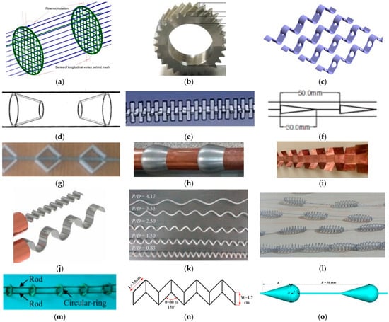
Figure 1.
Turbulators for heat transfer augmentation used in the previous studies. (a) circular ring–metal wire net [12], (b) helical surface disc [13], (c) horizontal perforated teardrop-shaped [24], (d) conical rings [14], (e) flow-divider-type turbulator [15], (f) conical turbulator [26], (g) zigzag-shaped turbulators [16], (h) digit NACA airfoil turbulator [17], (i) cut square turbulator [18], (j) semicircular-shaped turbulator [19], (k) wire coil turbulator [21], (l) wire coil turbulator [22], (m) circular-ring tabulators [20], (n) wavy strip turbulator [25], (o) spindle-shaped turbulators [23].
2. Experimental Setup and Numerical Details
2.1. Configuration of V-Shaped Delta-Wing Baffles
The V-shaped delta-wing baffles utilized in this research are illustrated in Figure 2. Each baffle was formed from a 0.8 mm thick (t) aluminum sheet with an inside diameter of 40 mm. These V-shaped winged baffles were fabricated with 3 numbers of wings (N = 4, 6, and 8) and periodically installed with a 10° attack angle (θ). In experiments, the V-shaped delta-wing baffles were thoroughly inserted inside a circular tube with various pitch ratios of P/D = 2.0, 2.5, and 3.0. The baffles were expected to generate recirculation/reverse flow behind the solid portion of the baffles and a longitudinal vortex flow behind the V-shaped wings.
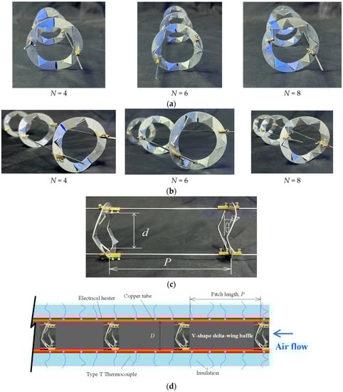
Figure 2.
Testing tube fitted with V-shaped delta-wing baffle turbulators. (a) front view. (b) isometric view. (c) side view. (d) test tube fitted with V-shaped delta-wing baffle turbulators.
2.2. Test Section and Apparatus
As shown in Figure 3, the tests were conducted in an open-loop experimental setup. The loop included a high pressure air blower, a control valve, an inverter, a digital pressure gauge, a data logger, an orifice-type flow meter, thermocouples, an AC power supply, and a test section. The total tube length was 3400 mm, which was subdivided into a 0.3 m long exit tube, a 1.6 m long calming section, and a 1.5 mm long testing tube (L). The system comprised a blower for providing room-temperature air at approximately 25 °C to the test section, which was connected to an orifice-type flow meter located adjacent to the test section. The speed of the high-pressure air blower motor was regulated as necessary using an inverter. According to Figure 2, the test section had a length of L = 1.5 m, an inner diameter of 62 mm, an outer diameter of 64 mm, and a thickness of 2.0 mm. To establish a constant wall heat flux, the test tube was heated by wrapping it with a flexible electrical heating wire. The exterior surface of the heating tube was adequately insulated to limit heat loss to the environment. The inlet and outlet temperatures were monitored at various locations using a data logger and T-type thermocouples. After 15 T-type thermocouples were attached to the tube’s surface and placed around it, the circumferential temperature variation was determined to be negligible. The thermocouples were calibrated using a thermostat and were found to have a precision of 0.1 °C. All temperature sensor signals generated by the system were captured utilizing a data logger. The pressure loss in the tube under tested section was recorded with a digital manometer, having a precision of 0.35%. During each test, the tests were carried out for 6000 ≤ Re ≤ 20,000. All fluid parameters were evaluated at their bulk air temperature.
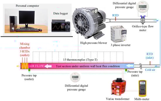
Figure 3.
Schematic diagram of experimental heat transfer setup.
2.3. Experimental Uncertainty
Reduced experimental data were examined to assess measurement uncertainties. The data uncertainty calculations were based on ref. [27]. The highest uncertainties of dimensionless Re, Nu and f were ±5.5%, ±8.6%, and ±8.1%, respectively, while the uncertainties of the pressure, axial air velocity, and wall temperature measurements were approximately ±6.8%, ±5.2%, and ±0.5%, respectively. Within these error margins, the results of the experiments were repeatable.
2.4. Experimental Uncertainty
Numerically, a three-dimensional turbulent investigation into the flow field and heat transfer behaviors in a round tube with V-shaped delta-wing baffles was performed. The numerical assessment was conducted based on the following assumptions: (1) the fluid is Newtonian, incompressible, continuous, and has constant physical properties; (2) V-shaped delta-wing baffles are rigid (the deformation and vibration of the insert are ignored) and the inserts were served as the insulator; and (3) thermal radiation, viscous heating, and gravity are not taken into consideration. It is presumed that the current numerical simulation of the flow structure and heat transfer behaviors is three-dimensional, turbulent, and steady. In the numerical method, at the entrance and exit of the flow domains, periodic boundaries were employed. The velocity profiles at the inlet and exit were similar. It is presumed that the physical characteristics of air remain constant at the average bulk temperature. On the surfaces of V-shaped delta-wing baffles and tube walls, an impermeable boundary and nonslip wall conditions were set up. It should be noted that the dimensionless temperatures at the entrance and exit were identical. The test section was supplied with air at a constant entrance temperature of 300 K and Reynolds number of 10,000. The conduit wall was subjected to an uniform heat flux of 600 W/m2.
3. Data Analysis
The major parameters determined in the current work are Nu, f, and the aerothermal performance factor (APF). Air is continually delivered into a testing section with constant heat flux. It is presumed that the heat absorbed by the air flow (Qair) and the convection of heat from the section being tested (Qconv) are identical.
where
The convective heat transfer can be expressed as
where
and
where Tw represents the local surface temperature of the outer tube wall. The average surface temperatures are evaluated at 15 sites located equidistant between the testing tube’s entrance and exit. The mean Nu and mean convective coefficient (h) are
The Reynolds number corresponds to
The friction factor, or f, corresponds to
where U, L and ΔP represent the mean velocity, the length of the testing tube, and the pressure drop, respectively. All air parameters were computed using the bulk air temperature provided by Equation (4).
The aerothermal performance factor (APF) is a suitable tool utilized to analyze the overall aero performance of an enhanced device. It is discussed in refs. [28,29] and is determined by the following balance between enhanced heat transfer ratio and friction factor ratio:
where which the subscript “0” indicates a plain tube.
APF = (Nu/Nu0)/(f/f0)1/3
4. Experimental Results and Discussion
4.1. Validation Test
Prior to experiments using the testing tube with V-shaped delta-wing baffle turbulators installed, experiments employing a plain tube were performed to develop benchmark results with the correlations of Dittus–Boelter [30]. This was performed to assess the reliability of the equipment and methodology.
Equation of Dittus and Boelter (1930),
Equation of Petukhov (1970),
The comparisons are demonstrated in Figure 4 and Figure 5. The experimental data agreed well with the equation of Petukhov and the equation of Dittus and Boelter, with errors within ±5.43% and ±5.19%, respectively.
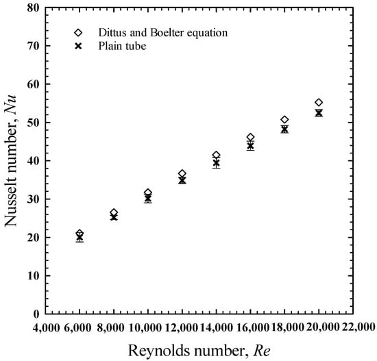
Figure 4.
Confirmation test of Nusselt numbers.
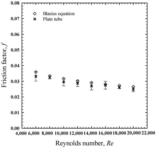
Figure 5.
Confirmation test of friction factors. Error bars added to all data-related figures.
4.2. Heat Transfer Enhancement Results
Figure 6a,b depict the experimental findings obtained under turbulent flow conditions for three different wing numbers of V-shaped winged baffles placed in a tube. In this figure, the Nusselt numbers are displayed as a function of the Reynolds number, with preliminary estimates utilizing the mass-averaged velocity. For comparison, the axial flow (plain tube) data are also provided. Due to the induction of a strong longitudinal vortex flow, the installed V-shaped winged baffles promoted heat transfer rates as compared to a plain tube for all Reynolds numbers. The best heat transfer rate was achieved at N = 8. With N = 8 (wings), the increased heat transfer rate over a plain tube alone ranged from 114.8% to 138.9% for Reynolds numbers between 6000 and 20,000. The increases were found to be roughly 97% to 120.4% for N = 4 and 105.8% to 127.8% for N = 6, although a similar trend was observed for V-shaped winged baffles with N = 8. The improvement was 7.1–9.3% more than those with N = 4 and 2.4–5.7% greater than those with N = 6.
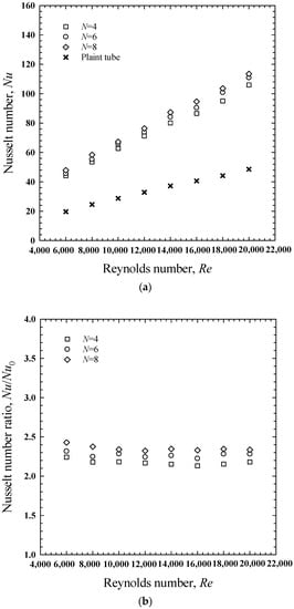
Figure 6.
Variation of the Nusselt number with the Reynolds number at different numbers of wings (N) and a constant pitch ratio (P/D) of 2.5. (a) Nu, (b) Nu/Nu0.
The plot of the mean Nusselt number and Nusselt number ratio versus Reynolds number at various pitch ratios (P/D) is displayed in Figure 7a,b. Obviously, heat transfer enhancement was more pronounced at a smaller pitch ratio (P/D). For P/D = 2.0, 2.5 and 3.0, the heat transfer rates, respectively, varied ranging from 118.3 to 151.3%, 114.8 to 138.9% and 94.5 to 127.5% compared to those of the plain tube. In other words, the heat transfer rates by the baffles having P/D = 2.0 were greater than those by the ones with P/D = 2.5 and P/D = 3.0 by 1.6–7.5% and 9.0–17.2%, respectively. With the aid of the results in Figure 8, it can be simply explained that as the pitch ratio decreases, the turbulence caused by secondary flows is more consistent throughout the enhanced tube since the adjacent baffles become closer. Consequently, the mixing of the fluid between the middle and the tube surface parts is more pronounced. On the other hand, the vortex becomes weakened before reaching the next baffle at a large pitch ratio, resulting in poorer heat transfer. The flow structure, temperature field and Nusselt number distribution in Figure 8a–c revealed that both recirculation/reverse and longitudinal vortex flows were created by the baffles. The former occurred behind the solid baffle area and the latter was observed behind the V-shaped wing. With more wings, the intensities of the reverse and vortex flows tended to increase and the fluid mixing between the two types of flows was subsequently enhanced, especially in the case of N = 8. The results can be attributed to the effect of an extra multi-vortex along the circumference of the baffles.
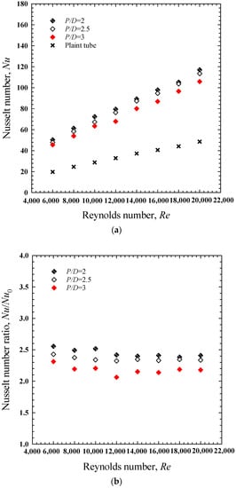
Figure 7.
Variation of the Nusselt number with the Reynolds number at different pitch ratios (P/D) and a constant number of wings (N) of 8. (a) Nu, (b) Nu/Nu0.
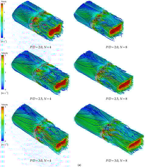
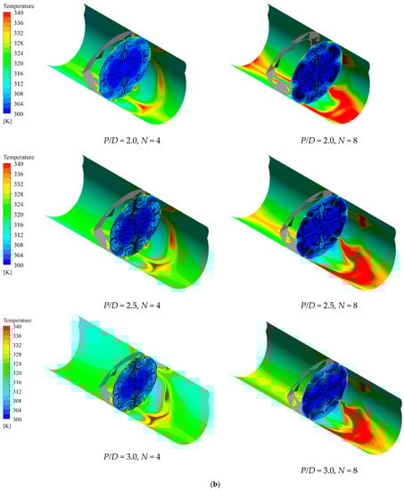
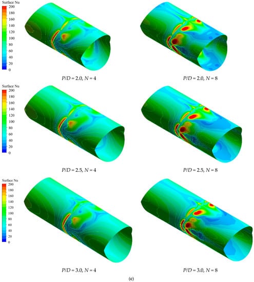
Figure 8.
Effect of numbers of wings (N) and pitch ratio (P/D) on the flow structure, temperature field and local Nusselt number at Reynolds number of 10,000. (a) flow structure, (b) temperature field, (c) local Nusselt number.
4.3. Friction Factor Results
Figure 9a,b depict the variation of the pressure losses in terms of friction factor over the test section as a function of the Reynolds number for three distinct numbers of wings (N). The presence of the turbulators resulted in an increased friction factor since circulation and longitudinal vortex flow were introduced. Additionally, pressure dissipation can be caused by the interplay of pressure and inertial forces in the boundary layer. Although the baffles with more wings generated more vortex flows, the friction factor decreased as the number of wings increased since the baffles possessed larger spaces. The open spaces allow fluid to flow more freely. Quantitative comparisons showed that the use of the baffles having N = 4 resulted in higher friction factors than the use of those having N = 6 and 8 by 12.2–25.6% and 39.4–50.9%, respectively. Additionally, the friction factors caused by V-shaped winged baffles with N = 4, 6 and 8 are, respectively, 29.6–31.9, 24.1–28.5 and 10.2–22.9 times that of a plain tube alone.
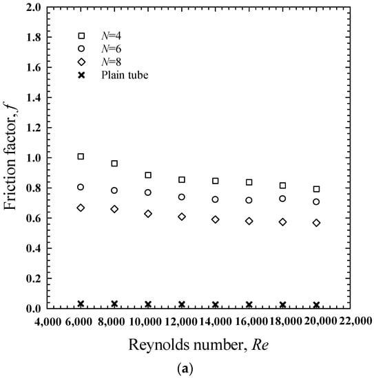
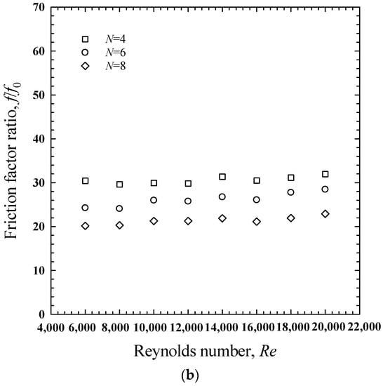
Figure 9.
Variation of the friction factor with the Reynolds number at different numbers of wings (N) and a constant pitch ratio (P/D) of 2.5. (a) f, (b) f/f0.
Figure 10a,b depict the variation of the friction factor with respect to the Reynolds number for the tube that was equipped with the V-shaped delta-wing baffles with various pitch ratios (P/D = 2.0, 2.5, and 3.0). As the Reynolds number and pitch ratio values increased, there was a general trend toward a reduction in the friction factor. Friction factors caused by the baffles having P/D = 3.0 dropped by 55.8–60.5% and 36.8–40.3% compared to those caused by the ones having P/D = 2.0 and 2.5, respectively. The results relate to the less consistent turbulence by the baffles with a larger pitch ratio, which are shown in Figure 8.
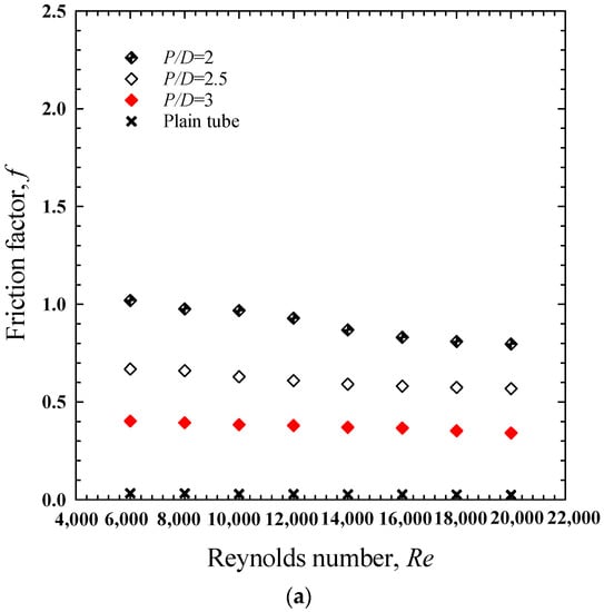
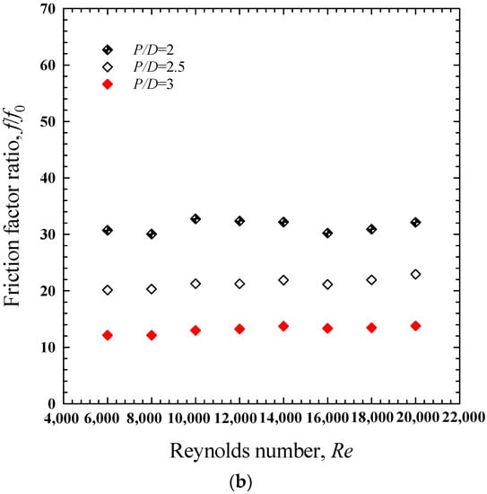
Figure 10.
Variation of the friction factor with the Reynolds number at different pitch ratios (P/D) and a constant number of wings (N) of 8. (a) f, (b) f/f0.
4.4. Aerothermal Performance Factor Results
The benefit of using the V-shaped winged baffles can be assessed at equal pumping power since energy consumption is crucial to the cost of operation. For constant pumping power [7,11,12,14,17,28,29],
Equation (13) can be derived and presented as the relationship between friction and the Reynolds number, as shown below.
With constant pumping power, the aerothermal performance factor (APF) is the ratio of the convective heat transfer coefficient of the tube with V-shaped delta-wing baffle turbulators to that of the plain tube as follows:
According to Figure 11, the aerothermal performance factor (APF) grew as the number of wings (N) increased and the Reynolds number decreased. The results suggest that saving energy using V-shaped delta-wing baffle turbulators is more practical at lower Reynolds numbers (Re ≤ 6000 for the current work). For the baffles with N = 4, 6, and 8, the aerothermal performance factor (APF) ranged between 0.68 and 0.7, 0.75 and 0.78, as well as 0.84 and 0.87, respectively. The high aerothermal performance factors yielded by the baffles with N = 8 were attributed to the low friction factor due to the reasons stated in Section 4.3, apart from their efficient heat transfer enhancement. Therefore, both excellent heat transfer and low friction factors must be taken into account for designing turbulators.
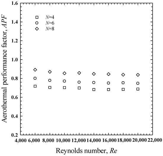
Figure 11.
Variation of aerothermal performance factor (APF) with the Reynolds number at different numbers of wings (N) and a constant pitch ratio (P/D) of 2.5.
Figure 12 displays the variation of the aerothermal performance factor (APF) relative to the Reynolds number for the tube that was fitted with the V-shaped delta-wing baffles in a variety of pitch ratios (P/D = 2.0, 2.5, and 3.0). At an identical Reynolds number, the baffles with a larger pitch ratio yielded greater aerothermal performance factors. Despite the baffles with a larger pitch ratio showing poorer heat transfer enhancement, their dominant effect on lower friction factors led to superior aerothermal performance factors.
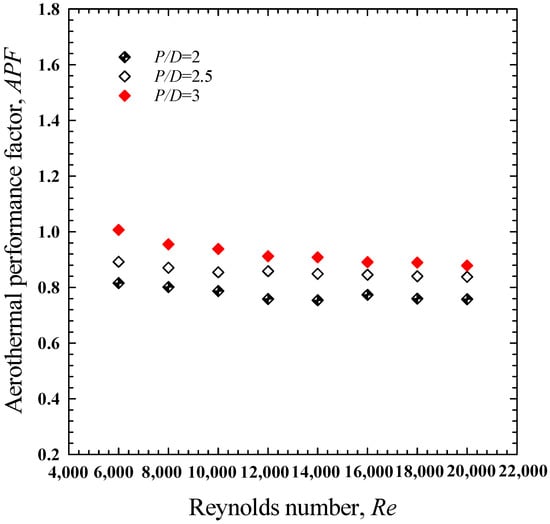
Figure 12.
Variation of aerothermal performance factor (APF) with the Reynolds number at different pitch ratios (P/D) and a constant number of wings (N) of 8.
4.5. Empirical Correlations
The empirical correlations developed from the experimental data of the tube with V-shaped delta-wing baffle turbulators between different numbers of wings (N) and the Nusselt number, friction factor and aerothermal performance factor (APF) are shown in Equations (16)–(18). All empirical correlations can be applied for the V-shaped delta-wing baffle turbulators for 2.0 ≤ P/D ≤ 3.0, 4.0 ≤ N ≤ 8.0, air as the working fluid with Pr = 0.71 and the flow with 6000 ≤ Re ≤ 20,000.
The correlations predict the Nusselt number (Nu) within ±6.54%, friction factor (f) within ±11.15%, and aerothermal performance factor (APF) within ±4.71%, as shown in Figure 13a–c.
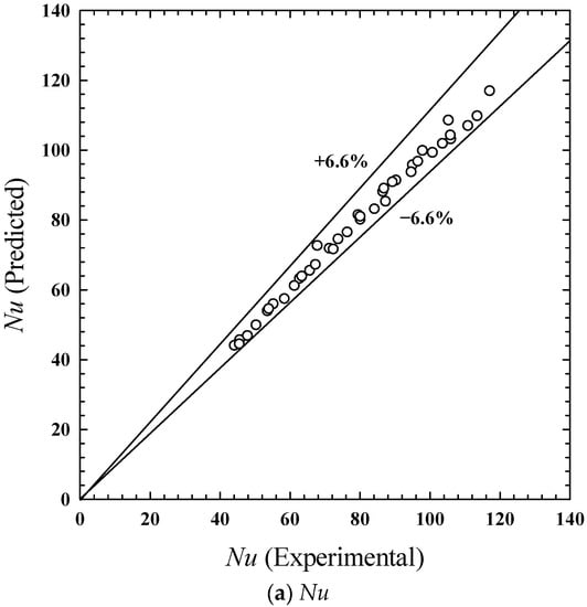
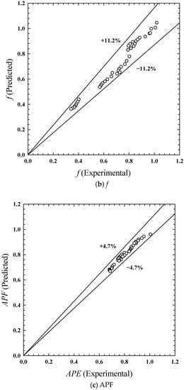
Figure 13.
Comparison of experimental and predicted (a) Nu, (b) f, and (c) APF.
4.6. Comparison with Previous Works
Figure 14a–c show the comparison of the Nusselt number (Nu), friction factor (f), and aerothermal performance factor (APF) which were associated by the V-shaped delta-wing baffle turbulators with P/D = 3.0 and N = 8 to those of the wavy strip turbulator [25], conical turbulator [26], serrated twisted tape [31], twisted tape [32], wire coil [33], and conical-nozzle [34]. All of the turbulators were compared at comparable Reynolds numbers (Re) and Prandtl numbers (Pr). The heat transfer rate and friction factor of the conical nozzle [34] were greater than those of the other turbulators. However, the conical nozzle yielded the lowest aerothermal performance factor (APF) due to its foremost effect of high friction loss. It can also be observed that most modified turbulators yielded a higher aerothermal performance factor (APF) than the conventional ones. The high APF offered by the V-shaped delta-wing baffle turbulators utilized in the current research was primarily influenced by the low flow block or pressure drop.
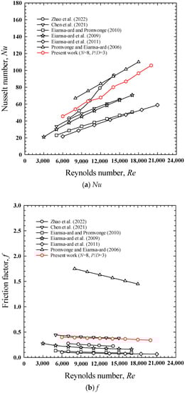
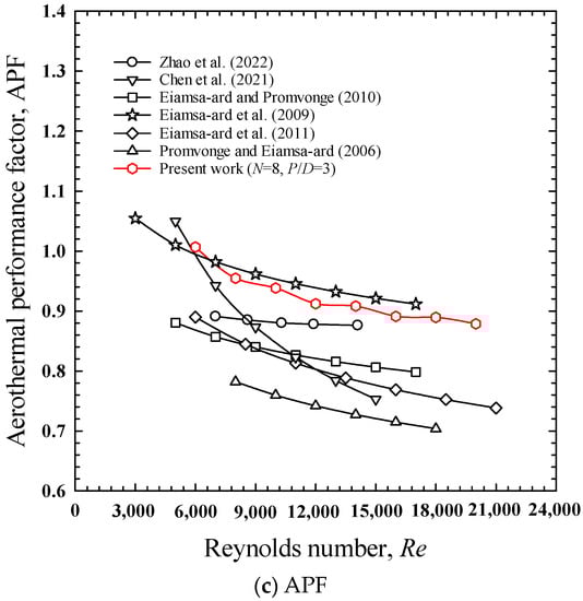
Figure 14.
Comparison between the current work and previous works [25,26,31,32,33,34]. (a) Nu, (b) f, (c) APF.
5. Conclusions
The effects of V-shaped delta-wing baffle turbulators with different numbers of wings on heat transfer, friction, and the aerothermal performance factor (APF) were experimentally studied. The following is an overview of the findings of the current research.
- ○
- Heat transfer can be enhanced by increasing fluid mixing between the core and the tube’s surface. This can be achieved by creating longitudinal vortex flow that mixes with the reverse flow along the baffles. Using V-shaped winged baffles with N = 4, 6, and 8 increased the mean heat transfer rates by 105.6%, 114.4%, and 122.6%, respectively, over that of a plain tube.
- ○
- The heat transfer rates were around 2.4% to 9.3% higher for N = 8 compared to N = 4 and N = 6, while N = 4 caused the maximum friction factor that was, respectively, 12.2–25.6% and 39.4–50.9% higher for N = 6 and 8.
- ○
- The baffles with a larger pitch ratio were less efficient in heat transfer augmentation, caused lower friction and yielded greater APF.
- ○
- For the baffles with N = 4, 6, and 8, the aerothermal performance factor (APF) ranged between 0.68 and 0.71, 0.75 and 0.78, and 0.84 and 0.87, respectively. Adoption of V-shaped wing baffles resulted in aerothermal performance factors (APFs) beyond unity in the low Reynolds number range (Re ≤ 6000).
Author Contributions
Conceptualization, C.T., N.M., M.H. and S.E.-a.; Methodology, P.S. and C.T.; Formal analysis, V.C.; Investigation, P.S., R.M., V.C. and S.E.-a.; Data curation, R.M. and V.C.; Writing—original draft, R.M.; Writing—review & editing, P.S. and C.T.; Supervision, N.M., M.H. and S.E.-a. All authors have read and agreed to the published version of the manuscript.
Funding
The Research on An Integrated Technology for Sustainable Development in the Agricultural Industry by King Mongkut’s Institute of Technology Ladkrabang (KMITL) has received funding support from the NSRF (FRB650028/0258).
Data Availability Statement
Not applicable.
Acknowledgments
This publication resulted (in part) from research on An Integrated Technology for Sustainable Development on Agricultural Industry by King Mongkut’s Institute of Technology Ladkrabang, which is supported by Thailand Science Research and Innovation (TSRI) funding (Grant No. FRB650028/0258).
Conflicts of Interest
The authors declare no conflict of interest.
References
- Bergles, A.E.; Webb, R.L. Guide to the literature on convection heat transfer augmentation. Adv. Enhanc. Heat Transf. 1985, 43, 81–89. [Google Scholar]
- Shelare, S.D.; Aglawe, K.R.; Belkhode, P.N. A review on twisted tape inserts for enhancing the heat transfer. Mater. Today Proc. 2022, 54, 560–565. [Google Scholar] [CrossRef]
- Poonpakdee, P.; Samutpraphut, B.; Thianpong, C.; Chokphoemphun, S.; Eiamsa-ard, S.; Maruyama, N.; Hirota, M. Heat Transfer Intensification in a Heat Exchanger by Means of Twisted Tapes in Rib and Sawtooth Forms. Energies 2022, 15, 8855. [Google Scholar] [CrossRef]
- Abed, N.; Afgan, I. An extensive review of various technologies for enhancing the thermal and optical performances of parabolic trough collectors. Int. J. Energy Res. 2020, 44, 5117–5164. [Google Scholar] [CrossRef]
- Rogowski, M.; Andrzejczyk, R. Recent advances of selected passive heat transfer intensification methods for phase change material-based latent heat energy storage units: A review. Int. Commun. Heat Mass Transf. 2023, 144, 106795. [Google Scholar] [CrossRef]
- Ajarostaghi, S.S.M.; Zaboli, M.; Javadi, H.; Badenes, B.; Urchueguia, J.F. A Review of Recent Passive Heat Transfer Enhancement Methods. Energies 2022, 15, 986. [Google Scholar] [CrossRef]
- Javanmard, S.; Ashrafizadeh, A. A comparative numerical study on heat transfer and pressure drops characteristics of perforated ribs. Int. J. Therm. Sci. 2023, 191, 108373. [Google Scholar] [CrossRef]
- Moria, H. Compound usage of twisted tape turbulator and air injection for heat transfer augmentation in a vertical straight tube with upward stream. Case Stud. Therm. Eng. 2021, 25, 100854. [Google Scholar] [CrossRef]
- Yakut, K.; Sahin, B. Flow-induced vibration analysis of conical rings used of heat transfer enhancement in heat exchanger. Appl. Energy 2004, 78, 273–288. [Google Scholar] [CrossRef]
- Yakut, K.; Sahin, B.; Canbazoglu, S. Performance and flow-induced vibration characteristics for conical-ring turbulators. Appl. Energy 2004, 79, 65–76. [Google Scholar] [CrossRef]
- Yaningsih, I.; Wijayanta, A.T.; Miyazaki, T.; Koyama, S. Thermal hydraulic characteristics of turbulent single-phase flow in an enhanced tube using louvered strip insert with various slant angles. Int. J. Therm. Sci. 2018, 134, 355–362. [Google Scholar] [CrossRef]
- Bartwal, A.; Gautam, A.; Kumar, M.; Mangrulkar, C.K.; Chamoli, S. Thermal performance intensification of a circular heat exchanger tube integrated with compound circular ring–metal wire net inserts. Chem. Eng. Process. Process Intensif. 2018, 124, 50–70. [Google Scholar] [CrossRef]
- Yadav, S.; Sahu, S.K. Heat transfer augmentation in double pipe water to air counter flow heat exchanger with helical surface disc turbulators. Chem. Eng. Process. Process Intensif. 2019, 135, 120–132. [Google Scholar] [CrossRef]
- Ibrahim, M.M.; Essa, M.A.; Mostafa, N.H. A computational study of heat transfer analysis for a circular tube with conical ring turbulators. Int. J. Therm. Sci. 2019, 137, 138–160. [Google Scholar] [CrossRef]
- Nalavade, S.P.; Prabhune, C.L.; Sane, N.K. Effect of novel flow divider type turbulators on fluid flow and heat transfer. Therm. Sci. Eng. Prog. 2019, 9, 322–331. [Google Scholar] [CrossRef]
- Mohammed, A.M.; Kapan, S.; Sen, M.; Celïk, N. Effect of vibration on heat transfer and pressure drop in a heat exchanger with turbulator. Case Stud. Therm. Eng. 2021, 28, 101680. [Google Scholar] [CrossRef]
- Mousavi, S.M.S.; Alavi, S.M.A. Experimental and numerical study to optimize flow and heat transfer of airfoil-shaped turbulators in a double-pipe heat exchanger. Appl. Therm. Eng. 2022, 215, 118961. [Google Scholar] [CrossRef]
- Hassan, J.H.; Hameed, V.M. Evaluate the hydrothermal behavior in the heat exchanger equipped with an innovative turbulator. South Afr. J. Chem. Eng. 2022, 41, 182–192. [Google Scholar] [CrossRef]
- Fang, Y.; Mansir, I.B.; Shawabkeh, A.; Mohamed, A.; Emami, F. Heat transfer, pressure drop, and economic analysis of a tube with a constant temperature equipped with semi-circular and teardrop-shaped turbulators. Case Stud. Therm. Eng. 2022, 33, 101955. [Google Scholar] [CrossRef]
- Lamlerd, B.; Bubphachot, B.; Chompookham, T. Experimental investigation of heat transfer characteristics of steam generator with circular-ring turbulators. Case Stud. Therm. Eng. 2023, 41, 102549. [Google Scholar] [CrossRef]
- Azmi, W.H.; Abdul Hamid, K.; Ramadhan, A.I.; Shaiful, A.I.M. Thermal hydraulic performance for hybrid composition ratio of TiO2-SiO2 nanofluids in a tube with wire coil inserts. Case Stud. Therm. Eng. 2021, 25, 100899. [Google Scholar] [CrossRef]
- Oflaz, F.; Keklikcioglu, O.; Ozceyhan, V. Investigating thermal performance of combined use of SiO2-water nanofluid and newly designed conical wire inserts. Case Stud. Therm. Eng. 2022, 38, 102378. [Google Scholar] [CrossRef]
- Izadi, M.; Alshehri, H.M.; Hosseinzadeh, F.; Rad, M.S.; Hamida, M.B.B. Numerical study on forced convection heat transfer of TiO2/water nanofluid flow inside a double-pipe heat exchanger with spindle-shaped turbulators. Eng. Anal. Bound. Elem. 2023, 150, 612–623. [Google Scholar] [CrossRef]
- Wang, H.; Abed, A.M.; Al-Zubaidi, A.; Deifalla, A.; Galal, A.M.; Zhou, Y.; Ghoushchi, S.P. Heat transfer enhancement of a copper tube with constant wall temperature using a novel horizontal perforated teardrop-shaped turbulators (PTST). Int. J. Therm. Sci. 2023, 192, 108418. [Google Scholar] [CrossRef]
- Zhao, J.; Reda, S.A.; Al-Zahrani, K.S.; Singh, P.K.; Amin, M.T.; Tag-Eldin, E.; Emami, F. Hydro-thermal and economic analyses of the air/water two-phase flow in a double tube heat exchanger equipped with wavy strip turbulator. Case Stud. Therm. Eng. 2022, 37, 102260. [Google Scholar] [CrossRef]
- Chen, H.; Ayed, H.; Marzouki, R.; Emami, F.; Mahariq, I.; Jarad, F. Thermal, hydraulic, exergitic and economic evaluation of a flat tube heat exchanger equipped with a plain and modified conical turbulator. Case Stud. Therm. Eng. 2021, 28, 101587. [Google Scholar]
- ASME PTC 19.1-2013; Test Uncertainty: Performance Test Codes. ANSI/ASME: New York, NY, USA, 2013; pp. 1–78.
- Jayranaiwachira, N.; Promvonge, P.; Thianpong, C.; Promthaisong, P.; Skullong, S. Effect of louvered curved-baffles on thermohydraulic performance in heat exchanger tube. Case Stud. Therm. Eng. 2023, 42, 102717. [Google Scholar] [CrossRef]
- Promvonge, P.; Promthaisong, P.; Skullong, S. Heat transfer augmentation in solar heat exchanger duct with louver-punched V-baffles. Sol. Energy 2022, 248, 103–120. [Google Scholar] [CrossRef]
- Incropera, F.; Dewitt, P.D. Introduction to Heat Transfer, 3rd ed.; John Wiley & Sons Inc.: Hoboken, NJ, USA, 1996; pp. 1–912. [Google Scholar]
- Eiamsa-ard, S.; Promvonge, P. Thermal characteristics in round tube fitted with serrated twisted tape. Appl. Therm. Eng. 2010, 30, 1673–1682. [Google Scholar] [CrossRef]
- Eiamsa-ard, S.; Thianpong, C.; Eiamsa-ard, P.; Promvonge, P. Convective heat transfer in a circular tube with short-length twisted tape insert. Int. Commun. Heat Mass Transf. 2009, 36, 365–371. [Google Scholar] [CrossRef]
- Eiamsa-ard, S.; Kongkaitpaiboon, V.; Promvonge, P. Thermal performance assessment of turbulent tube flow through wire coil turbulators. Heat Transf. Eng. 2011, 32, 957–967. [Google Scholar] [CrossRef]
- Promvonge, P.; Eiamsa-ard, S. Heat transfer enhancement in a tube with combined conical-nozzle inserts and swirl generator. Energy Convers. Manag. 2006, 47, 2867–2882. [Google Scholar] [CrossRef]


Disclaimer/Publisher’s Note: The statements, opinions and data contained in all publications are solely those of the individual author(s) and contributor(s) and not of MDPI and/or the editor(s). MDPI and/or the editor(s) disclaim responsibility for any injury to people or property resulting from any ideas, methods, instructions or products referred to in the content. |
© 2023 by the authors. Licensee MDPI, Basel, Switzerland. This article is an open access article distributed under the terms and conditions of the Creative Commons Attribution (CC BY) license (https://creativecommons.org/licenses/by/4.0/).