Abstract
This article presents the possibility of increasing the efficiency of a vertical-axis wind generator through the introduction of an automatic control system for the angle of attack of the blades. The calculation of the optimal position of the wind turbine blades for the maximum generation of electrical energy is given, and a developed scheme for controlling the blades using the sensors of the angular speed of rotation of the wind wheel by the anemometer and the current position of the blades is presented. The automatic control system implies the use of a PD controller. A comparison is made of two laboratory experimental models of vertical-axis wind turbines with and without the developed control system. This article focuses on optimizing the angle of attack and developing an automatic control system for vertical-axis wind turbines to increase their efficiency in generating electrical energy.
1. Introduction
Due to the volatility of electricity prices and environmental pollution, wind energy is a promising way to solve these problems. Renewable energy sources, in particular wind farms, are becoming more popular every year. According to IRENA, by 2040 many countries plan to completely switch to the use of alternative energy sources [1]. Today, wind energy has become so popular in many countries of the world that it competes with traditional energy sources. For example, in Spain and Denmark, the energy received from renewable sources exceeds in volume the energy that is generated in the traditional way [2]. Of all the renewable energy sources in Kazakhstan, wind power is the most significant. The possible potential of wind energy is calculated to be from 0.929 to 1.82 billion kWh per year [3], which corresponds to 3 billion kWh of energy per year. Comparison of the wind potential with the consumption of electricity in the country suggests that wind turbines are able to generate 15 times more electricity than Kazakhstan needs [4]. The most promising area for the placement of wind turbines is the Shelek corridor, Dzhungar gates, Akmola region, Zhambyl region, according to studies conducted under the UN Development Program on wind energy [5]. Also, it was found that in Kazakhstan there are more than 50 thousand square kilometer areas with an average annual wind speed of 6 m/s or more. Thus, the topic of wind energy development in Kazakhstan is relevant. The wind wheel converts the energy of the wind flow into rotational energy, then the rotational energy is converted into electrical energy using a generator system. The frequency of rotation of the generator and the wind wheel is constant when the power required to compensate for the moment of resistance from the generator corresponds to the power expended by the wind wheel from the wind. If this condition is not met, the wind wheel starts to slow down. Vertical-axis wind turbines and horizontal-axis wind turbines are the two main types of wind-energy extraction devices, with horizontal-axis wind turbines widely used in commercial wind farms but which are facing logistical difficulties and complex control systems. Vertical-axis wind turbines offer advantages such as quick wake recovery, closer packing for higher power densities, and smaller size [6].
Today, there is a development of and improvement in the mechanical part and electronic control circuits of wind turbines and new methods of controlling them are emerging. For example, there are methods for controlling a wind generator at fixed rotor speeds [7]. The essence of this method is to switch the windings of the generator or change the gear ratio of the multiplier. There are also options for the operation of wind turbines at a variable speed, where control is carried out by changing the geometric parameters of the rotor, changing the angle of attack of the wind flow on the blades, or by using a power controller. The simplest method of controlling the output power of a wind turbine is the control method at a constant speed [8]. The disadvantages of this method are:
- -
- the efficiency of the wind generator is possible in a limited range of wind speeds;
- -
- there is a problem of protecting the wind generator when the nominal value of the wind speed is exceeded.
The method of convergence with the control method at a constant speed is also known, but in contrast to it, in this method, the output voltage of the generator changes depending on the value of the wind speed, which ensures the productive operation of the wind generator at various speeds [9]. The disadvantages of this method are:
- -
- the need to apply wind speed measurement systems;
- -
- low level of reliability of the electronic part of the wind generator due to the use of switching mechanisms for the winding of the generator;
- -
- there is a problem of providing the wind generator with protective mechanisms when the nominal value of the wind speed is exceeded.
Another option for power output control is the method of changing the angle of attack on the blades by changing the parameters of the wind wheel. This method involves the use of various mechanisms, where the automated control of the mechanical part of the wind generator is performed in accordance with the change in the value of the wind speed [10].
The disadvantages of this method include:
- -
- the need to use complex mechanisms and additional automation systems;
- -
- higher costs for a wind power plant due to the complexity of the design and, accordingly, greater material consumption.
Adjustment of the wind power utilization factor is possible via turning the blade around the swing axis; changing the angle of attack of the blade produces a change in the proportion of energy taken from the wind. It follows that changing the angle of attack of the blade allows you to adjust the amount of energy taken from the wind, maintaining a balance of power and keeping the frequency rotation of the shaft of the wind wheel and the generator constant. To obtain the maximum energy from the wind generator at any wind speed, it is necessary to control the rotation speed in such a way that the turbine rotation speed corresponds to the optimal value at the current wind speed. Also, for each value of the speed of wind flow, there is a maximum power at the speed of rotation of the wind wheel [11]. Angle of attack control is crucial for vertical-axis wind turbines (VAWTs) to optimize their performance throughout the rotation [12]. VAWTs experience significant changes in their angle of attack as they rotate, and actively adjusting this angle allows for improved efficiency and power generation. The angle of attack refers to the angle between the oncoming wind direction and the rotor blade. It directly influences the lift and drag forces acting on the blades, which in turn affect the turbine’s power output and overall performance [13]. By dynamically controlling the angle of attack, VAWTs can adapt to varying wind conditions and extract more energy from the wind. There are several reasons why angle of attack control is necessary for VAWTs:
- -
- Aerodynamic Efficiency—By adjusting the angle of attack, the turbine blades can be positioned optimally to harness the maximum amount of wind energy [14]. At a certain angle, the blades generate the highest lift and minimize drag, leading to improved efficiency and power production. As the wind direction changes with the turbine rotation, controlling the angle of attack allows the blades to maintain an optimal orientation and maximize energy capture [15];
- -
- Start-Up and Cut-In Speed—VAWTs often face challenges during startup and at low wind speeds. By adjusting the angle of attack, the blades can be set to generate sufficient lift to initiate rotation even at low wind speeds [16]. Controlling the angle of attack allows VAWTs to start operating earlier and achieve their cut-in speed (the minimum wind speed required for the turbine to start generating power) more effectively;
- -
- Performance at Different Wind Speeds—Wind speed is not constant, and it varies with height and atmospheric conditions. VAWTs experience changing wind speeds as the rotor rotates, which affects the angle of attack [17]. By actively controlling the angle, the turbine can optimize power production by adjusting to the wind speed changes. Higher wind speeds may require a lower angle of attack to prevent excessive loads on the blades, while lower wind speeds may require a higher angle of attack to maintain lift and power generation [18];
- -
- Load Mitigation—VAWTs are subjected to cyclic loading as the blades pass through the wind stream [19]. These cyclic loads can lead to fatigue and structural damage over time. By adjusting the angle of attack, the turbine can manage the distribution of loads on the blades, reducing stress concentrations and extending the lifespan of the turbine [20].
To achieve angle of attack control, VAWTs employ various mechanisms such as blade pitching, twisting, or using airfoils with variable camber. These control systems continuously monitor wind conditions, rotor position, and other factors to determine the optimal angle of attack for each blade at any given moment [21]. This dynamic adjustment allows VAWTs to optimize their performance and extract the maximum energy from the wind, despite the substantial changes in the angle of attack during rotation.
By utilizing dynamic angle of attack control, vertical-axis wind turbines can optimize their performance throughout the rotation [22]. The angle of attack adjustment allows for improved aerodynamic efficiency, enabling the blades to capture the maximum wind energy. It also aids in the turbine’s start-up and operation at low wind speeds, enhances performance across different wind speeds, and helps mitigate cyclic loads and potential structural damage [23]. These benefits are achieved through mechanisms like blade pitching, twisting, or using airfoils with variable camber, which continuously monitor wind conditions and adjust the angle of attack for each blade.
2. Materials and Methods
To begin with, the optimal position of the wind generator blades was determined, which allowed us to obtain maximum energy from the wind. The power Pk generated by the wind generator depended on the power of each blade of the wind generator in accordance with the formula [24]:
where Pi is the power of each of the blades.
To achieve maximum efficiency of the wind generator, its blades must create the optimal value of aerodynamic resistance, changing their position with changes in wind speed and direction in order to use the wind force FB to the maximum extent in accordance with the formula [25]:
where m is the mass of wind flow, VB is the wind speed.
Figure 1 shows the optimal arrangement of the blades which will use the force of the wind to its maximum extent.
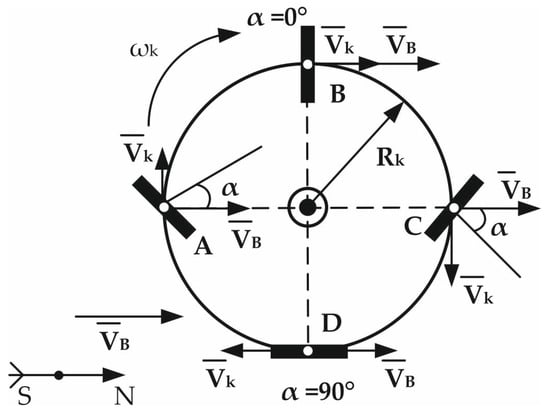
Figure 1.
The position of the blades in accordance with the current direction of the wind and the angular velocity of rotation.
Since the wind speed and its direction are not constant values, it is necessary to develop a control system to ensure a given position of the blades with a changed wind direction and a given rotor speed . In addition, for the effective operation of the automatic blade control system, it is necessary to have information on not only , , but also on the linear speed of the rotor , as well as the influence of these parameters on the current value of the angular position of the blades α. To do this, it is necessary to determine the power generated by the blades A and C, in accordance with the formula [26]:
where ρ is the air density, S is the area of the blade, VL is the linear speed of the blade, and α is the angle between the direction of the wind flow velocity and a certain blade perpendicular to the plane.
Next, the partial derivative of the powers generated by the blades A and C with respect to the angular position of the blades is determined α [27]:
Next, the expression 4 is equated to 0 and the value of the angular position of the blades is expressed α:
We considered the linear speed of the blade to be equal to:
where is the angular speed of the rotor, R is the radius of the wind wheel.
Thus, the final expression becomes:
In accordance with expression (7), to install the blades A and C, it is necessary to adjust the control system using the sensors of the angular speed of rotation of the wind wheel, ωK, according to the anemometer (wind speed device). Expression (7) determines the initial value of the position of the angle of the blades A and C. The rotation of the blades during the rotation of the wind wheel occurs relative to this angle with an angular velocity ωK. When blades A and C are set at the angle calculated in accordance with expression (7), blade B should receive the maximum amount of wind flow, while the plane of the blade is perpendicular to the direction of the wind, and, accordingly, blade D should be parallel to VV to ensure the minimum value of aerodynamic drag. When the wind direction changes, the automatic blade control system will change the control signal in time and the blades will turn according to the control signals ωK, φ (the angle of change in wind direction). The control is performed in accordance with Figure 2 and Table 1 (time delay when changing the angle of attack of the blades when changing wind direction).
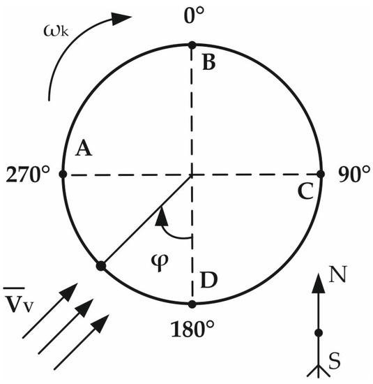
Figure 2.
Changing the angle of wind direction by the angle φ.

Table 1.
Time delay when changing the angle of attack of the blades with a change in wind direction.
To select the type of regulation, a study was conducted in the TIA Portal software environment. The block “CONT_C” was chosen, which is used in programmable logic controllers of technological processes of continuous inputs and outputs of variables (Figure 3).
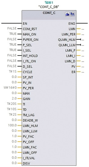
Figure 3.
Block “CONT_C”.
To select the type of regulation, the regulator in the open state was considered. The necessary parameters for the study of the P-controller were set at GAIN = 1 and GAIN = 1.5. The results are shown in Figure 4 and Figure 5.
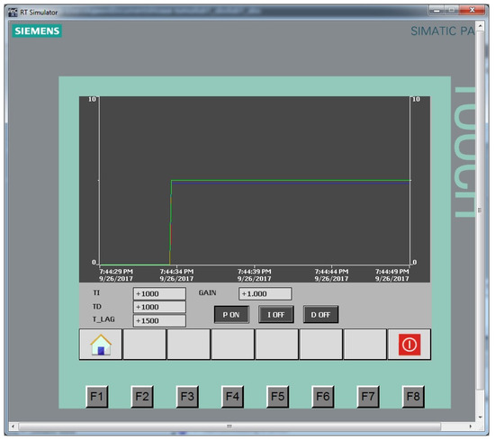
Figure 4.
P-controller with GAIN = 1 red line is the control action, green line is the setting signal, blue line is the output control signal.
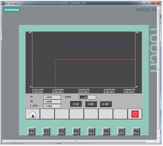
Figure 5.
P-regulator with GAIN = 1.5: red line is the control action, green line is the setting signal, blue line is the output control signal.
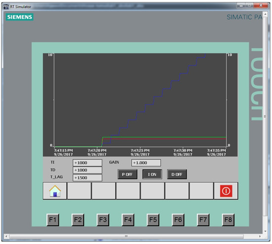
Figure 6.
I-controller at TI = 1 s: red line is the control action, green line is the setting signal, blue line is the output control signal.

Figure 7.
I-controller at TI = 5 s: red line is the control action, green line is the setting signal, blue line is the output control signal.
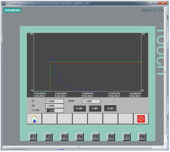
Figure 8.
D-regulator at TD = 2 s: red line is the control action, green line is the setting signal, blue line is the output control signal.
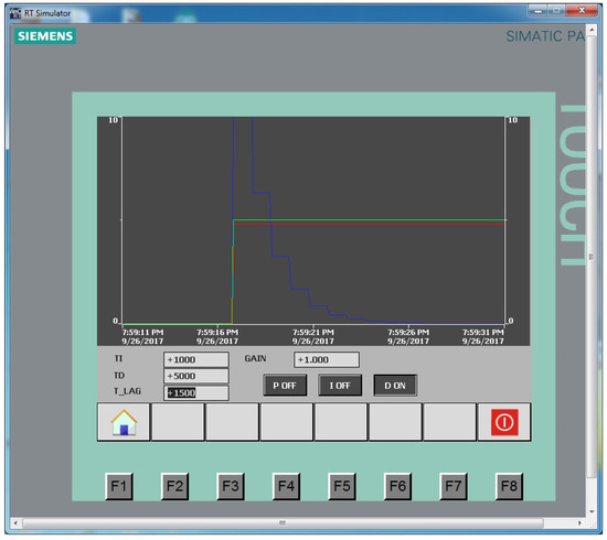
Figure 9.
D-regulator at TD = 5 s: red line is the control action, green line is the setting signal, blue line is the output control signal.
Next, the behavior of the controller with a simulated aperiodic plant was studied. Figure 10 and Figure 11 show the P-controller with GAIN = 2 and GAIN = 10, respectively.
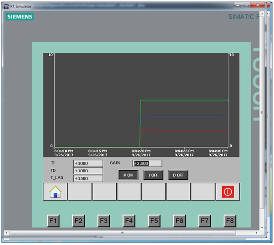
Figure 10.
P-controller with GAIN = 2: red line is the control action, green line is the setting signal, blue line is the output control signal.
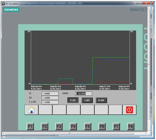
Figure 11.
P-controller with GAIN = 10: red line is the control action, green line is the setting signal, blue line is the output control signal.
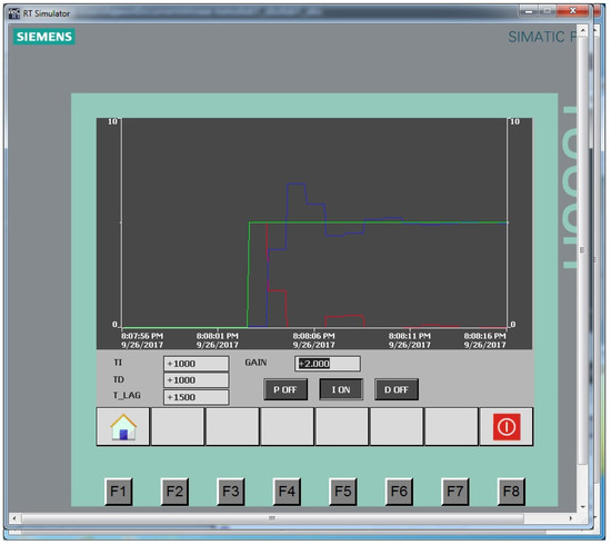
Figure 12.
I-controller at TI = 1 s: red line is the control action, green line is the setting signal, blue line is the output control signal.
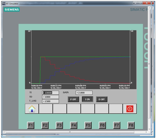
Figure 13.
I-controller at TI = 10 s: red line is the control action, green line is the setting signal, blue line is the output control signal.
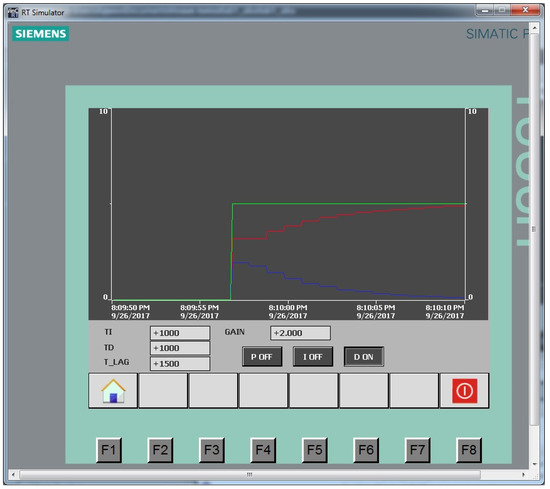
Figure 14.
D-regulator at TD = 1 s: red line is the control action, green line is the setting signal, blue line is the output control signal.
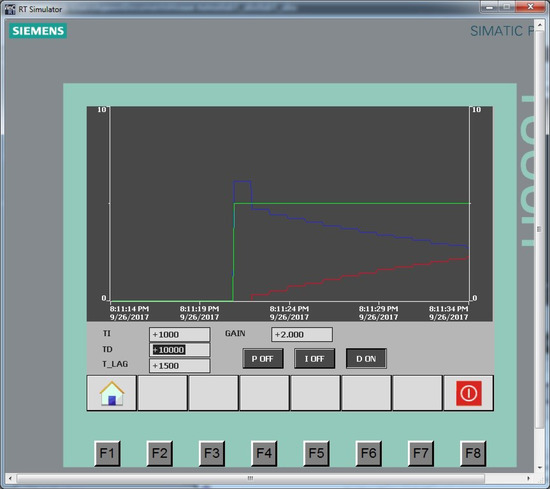
Figure 15.
D-regulator at TD = 10 s: red line is the control action, green line is the setting signal, blue line is the output control signal.
The studies shown in Figure 4, Figure 5, Figure 6, Figure 7, Figure 8, Figure 9, Figure 10, Figure 11, Figure 12, Figure 13, Figure 14 and Figure 15 show that the I-component allows you to compensate for the static error, and the D-component reduces the regulation time. An increase in the integration time leads to a slower rise in the I-component, and an increase in the differentiation time leads to an increase in the peak of the D-component. Thus, based on these results, the type of regulation was chosen and a scheme was developed.
Next, a mathematical model for controlling the angle of attack of the wind turbine blades was determined. In accordance with the calculations given above, a general functional diagram for controlling the blades of a vertical-axis wind generator was developed (Figure 16). Let us assume that the wind direction is south–north. The functional diagram includes 4 control channels for four blades A, B, C, and D. Setting the position of the blades depends on the direction of the wind flow, power calculation, angular speed of rotation of the wind generator, and wind speed. To take into account the above parameters, the use of sensors and setters in the feedback circuit is provided. Next, you need to determine the type of regulator and the law of regulation. Figure 17 shows a diagram of one channel for controlling the position of a wind turbine blade. In accordance with Figure 18, elements 1, 2, 3, and 4 set the desired position of the blade based on the values of the wind flow velocity and wind generator rotation. Next, it is necessary to determine the choice of control law, based on these parameters:
where is the servo angle, is the conversion factor, is the actual angle of rotation, αS is the angle reference, and is the blade angular velocity.
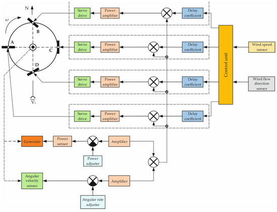
Figure 16.
A general functional diagram of the blade control of a vertical-axis wind generator: A, B, C, D—control channels for four blades.
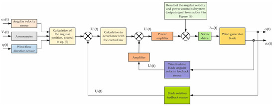
Figure 17.
Scheme of one channel for controlling the position of the wind turbine blade.
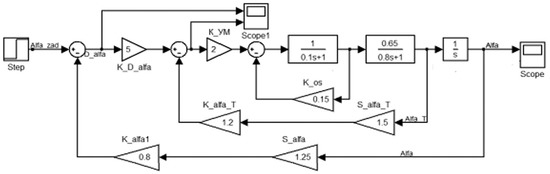
Figure 18.
Mathematical model of wind turbine blade control.
The value of the setting value of the angle was calculated in accordance with Formula (7) and Table 1 in block 4 in Figure 17. Next, a mathematical model of the blade attack angle control system was developed; for this, the MatLab/Simulink simulation environment was used, shown in Figure 18. The results of modeling the mathematical model are shown in Figure 19.
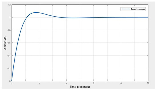
Figure 19.
Simulation result.
Figure 19 shows the simulation result of the developed wind turbine blade control system. As can be seen from it, the transition process setting time is 3 s, which is the optimal value when controlling the wind turbine blades. As can be seen, the blade position control system is robotic.
3. Results
On the basis of the obtained calculations and mathematical models, two laboratory models were assembled that have the same characteristics in terms of dimensions and materials of manufacture. The model shown in Figure 20 does not have a blade position control system, while the model shown in Figure 21 includes the control system designed and described. A stepper motor was used as a generator for both models. MG996R servo drives were used as an actuator for controlling the wind turbine blades in the model with a control system (Figure 21).
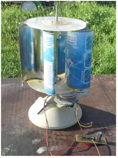
Figure 20.
Experimental model of a wind turbine without a control system.
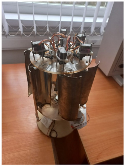
Figure 21.
Experimental model of a wind generator with a developed control system.
With the help of the laboratory software and hardware complex Petom-51 (Figure 22), the values of the output voltage for both models were obtained by supplying a wind flow at a speed of 25 m/s. Figure 23 shows the voltage output characteristic for a wind turbine model without a control system (Figure 20). Figure 24 shows the voltage output characteristic for a wind turbine model with a control system (Figure 21).
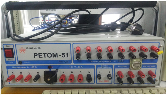
Figure 22.
Software and hardware complex Petom-51.
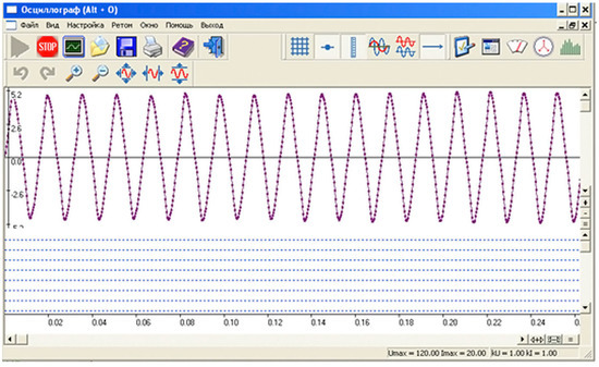
Figure 23.
Voltage output signal from the laboratory model without the implementation of the developed control system (the vertical axis is the voltage amplitude V, and the horizontal axis is the time, s).
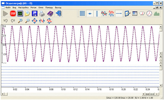
Figure 24.
Voltage output signal from the laboratory model with the introduction of the developed control system (the vertical axis is the voltage amplitude V, and the horizontal axis is the time, s).
In the course of the work, a system for automatically controlling the angle of rotation of the blades of a vertical-axis wind generator was developed and tested. Figure 23 and Figure 24 show the values of the output voltage amplitude for two wind turbine models. The voltage amplitude for the wind turbine model without a control system was 5.2 V. After the introduction of the control system described in this paper into the wind generator, the voltage amplitude became 5.6 V. The developed control system was able to increase the efficiency of vertically axial wind turbines. Thus, the efficiency of using the developed control system corresponded to 7.69%. The proposed calculation method does not pay attention to the losses in electricity associated with the rotation of the servos, since these losses can vary depending on factors such as materials, dimensions, and other characteristics of wind turbines. The main purpose of this article is to develop and demonstrate the control system, as well as to test its performance. In this case, the main emphasis is on the practical implementation of the control unit and its effectiveness.
Further, to calculate the efficiency from the introduction of the control system, calculations were made of the generated value of the output power of two wind turbines with and without the developed control unit, taking into account the experimental and calculated data given earlier. Since it was found that the efficiency of a wind generator with an embedded control unit is 7.69% higher than that of a wind generator without a control system, the power generated by a wind generator with a control system can be found by the formula [28]:
where is the generated power of a wind generator without a control system, and is the value of the increase in efficiency.
For comparison, a vertical-axis industrial wind generator with a nominal power of 4 kW was chosen, the instantaneous power data depending on the wind speed were taken from the literature [27], and, in accordance with the following expression, the values of the daily electricity generation by the wind generator were calculated [29]:
where P is the daily generation of electrical energy, and t is time (24 h).
The calculation data for the daily generation of electrical energy of a wind generator without a control system are shown in Table 2. The calculation of the daily generation of a wind generator with an embedded control unit is listed in Table 3.
Table 2.
Characteristics of an industrial wind turbine without a control system.
Table 3.
Characteristics of an industrial wind turbine with a control system.
For an example of calculating the effectiveness of the implementation of the control unit, let us take the value of electricity consumption per hour as equal to 390.8 kWh, or 390,805 Wh, and the value of the wind speed as 10 m/s. Thus, it is necessary to use 135 wind turbines with a nominal power of 4 kW or 41 wind turbines with a power of 10 kW.
Next, it is necessary to carry out a similar calculation for a wind generator with an embedded control unit. For the calculation, the wind speed is also taken as 10 m/s and the average consumption per hour is 390.8 kWh, or 390,805 W * h. Thus, it is necessary to use 126 wind turbines with a control unit with a rated power of 4 kW or 38 wind generators with a power of 10 kW. Figure 23 and Figure 24 shows a comparison of the daily power generation of a vertical-axis wind turbine with and without an embedded control unit. Thus, from the introduction of a control unit into a wind generator with a vertical axis of rotation, the savings are three wind generators with a rated power of 10 kW.
4. Conclusions
As a result of studying the components of a standard PID controller and developing the wind turbine blade control system, an optimal control law for the blades was selected based on calculations and mathematical models. The developed control system underwent successful testing using a mathematical model in the MatLab program and conducting experiments. The obtained experimental data confirm the robotic capability of the developed wind turbine blade control system. By accurately positioning blades A and C through control system adjustments and utilizing sensors for angular speed of the rotor and an anemometer, optimal performance of the wind turbine was achieved. Blade B receives the maximum wind flow, while blade D is oriented parallel to the wind direction to minimize aerodynamic drag. The implementation of the automated control system resulted in a 7.69% increase in the efficiency of the wind turbine, based on experimental data. This demonstrates the potential of the developed system to enhance the operation of wind turbines and improve the energy efficiency of wind power installations. Based on the conducting calculations, the incorporation of a control unit in a vertical-axis wind generator yields savings equivalent to three wind generators with a nominal power of 10 kW. This highlights the significant impact and efficiency achieved through the implementation of control mechanisms in vertical-axis wind turbines.
Further research in the field of wind turbine blade control can focus on improving the accuracy of the control system, reducing the transient response time, and optimizing the generator’s efficiency. Exploring alternative control algorithms and employing more accurate sensors can enhance the reliability and stability of the system. These advancements will continue to enhance the efficiency and reliability of wind power installations, contributing to sustainable development and environmental effectiveness in the renewable energy sector.
Author Contributions
Conceptualization, A.F. and T.I.; methodology, A.F., I.S., and T.I.; software, A.F., I.S., and T.I.; validation, all; formal analysis, all; investigation, all; writing—original draft preparation, all; writing—review and editing, A.F., T.I., and I.S.; visualization, A.F., T.I., and I.S.; contributed to the interpretation of the results, B.T. and I.B. All authors have read and agreed to the published version of the manuscript.
Funding
This research received no external funding.
Data Availability Statement
Data are obtained in the article.
Acknowledgments
This article is based on research conducted within the framework of the project ‘Development of a control and monitoring system for a multi-blade vertical-axis wind turbine’ (Project ID: AP19679162).
Conflicts of Interest
The authors declare no conflict of interest.
References
- Alvarez-Alvarado, M.S.; Rengifo, J.; Gallegos-Núñez, R.M.; Rivera-Mora, J.G.; Noriega, H.H.; Velasquez, W.; Donaldson, D.L.; Rodríguez-Gallegos, C.D. Particle Swarm Optimization for Optimal Frequency Response with High Penetration of Photovoltaic and Wind Generation. Energies 2022, 15, 8565. [Google Scholar] [CrossRef]
- Crespo, A. Wakes of Wind Turbines in Yaw for Wind Farm Power Optimization. Energies 2022, 15, 6553. [Google Scholar] [CrossRef]
- Sajadi, M.; De Kooning, J.D.M.; Vandevelde, L.; Crevecoeur, G. Harvesting wind gust energy with small and medium wind turbines using a bidirectional control strategy. J. Eng. 2019, 17, 4261–4266. [Google Scholar] [CrossRef]
- Fazylova, A.R.; Balbayev, G.; Tultayev, B. System of short-term forecasting of wind turbine output power consumption. In News of the National Academy of Sciences of the Republic of Kazakhstan, Series of Geology and Technical Sciences; National Academy of Sciences of the Republic of Kazakhstan: Almaty, Kazakhstan, 2022; Volume 2022, pp. 243–252. [Google Scholar]
- Al-Faruk, A.; Sharifian, A. Flow Field and Performance Study of Vertical Axis Savonius Type SST Wind Turbine. Energy Procedia 2017, 110, 235–242. [Google Scholar] [CrossRef]
- Gharaati, M.; Xiao, S.; Wei, N.J.; Martínez-Tossas, L.A.; Dabiri, J.O.; Yang, D. Large-eddy simulation of helical-and straight-bladed vertical-axis wind turbines in boundary layer turbulence. J. Renew. Sustain. Energy 2022, 14, 053301. [Google Scholar] [CrossRef]
- Soua, S.; Van Lieshout, P.; Perera, A.; Gan, T.H.; Bridge, B. Determination of thecombined vibrational and acoustic emission signatureof a wind turbine gearbox and generator shaft inservice as a pre-requisite for effective conditionmonitoring. Renew. Energy 2013, 51, 175–181. [Google Scholar] [CrossRef]
- Boukhezzar, B.; Siguerdidjane, H.; Maureen Hand, M. Nonlinear control of variable-speed wind turbines for generator torque limiting and power optimization. ASME Trans. J. Sol. Energy Eng. 2006, 128, 516–530. [Google Scholar] [CrossRef]
- Johnson, K.E.; Pao, L.Y.; Balas, M.J.; Fingersh, L.J. Control of variable-speed wind turbines: Standard and adaptive techniques for maximizing energy capture. IEEE Control. Syst. Mag. 2006, 26, 70–81. [Google Scholar]
- Xu, S.; Shao, R.; Chang, L.; Church, C. Energy cost estimation of small wind power systems –an integrated approach. IEEE J. Emerg. Sel. Top. Power Electron. 2015, 3, 945–956. [Google Scholar] [CrossRef]
- Belmili, H.; Cheikh, R.; Smail, T.; Seddaoui, N.; Biara, R.W. Study, design and manufacturing of hybrid vertical axis Savonius wind turbine for urban architecture. Energy Procedia 2017, 136, 330–333. [Google Scholar] [CrossRef]
- Rainone, C.; De Siero, D.; Iuspa, L.; Viviani, A.; Pezzella, G. A Numerical Procedure for Variable-Pitch Law Formulation of Vertical-Axis Wind Turbines. Energies 2023, 16, 536. [Google Scholar] [CrossRef]
- Martini, F.; Ibrahim, H.; Contreras Montoya, L.T.; Rizk, P.; Ilinca, A. Turbulence Modeling of Iced Wind Turbine Airfoils. Energies 2022, 15, 8325. [Google Scholar] [CrossRef]
- Aziz, S.; Khan, A.; Shah, I.; Khan, T.A.; Ali, Y.; Sohail, M.U.; Rashid, B.; Jung, D.W. Computational Fluid Dynamics and Experimental Analysis of a Wind Turbine Blade’s Frontal Section with and without Arrays of Dimpled Structures. Energies 2022, 15, 7108. [Google Scholar] [CrossRef]
- Siddappaji, K.; Turner, M. Improved Prediction of Aerodynamic Loss Propagation as Entropy Rise in Wind Turbines Using Multifidelity Analysis. Energies 2022, 15, 3935. [Google Scholar] [CrossRef]
- Li, L.; Chopra, I.; Zhu, W.; Yu, M. Performance Analysis and Optimization of a Vertical-Axis Wind Turbine with a High Tip-Speed Ratio. Energies 2021, 14, 996. [Google Scholar] [CrossRef]
- Hou, L.; Shen, S.; Wang, Y. Numerical Study on Aerodynamic Performance of Different Forms of Adaptive Blades for Vertical Axis Wind Turbines. Energies 2021, 14, 880. [Google Scholar] [CrossRef]
- Delafin, P.-L.; Deniset, F.; Astolfi, J.A.; Hauville, F. Performance Improvement of a Darrieus Tidal Turbine with Active Variable Pitch. Energies 2021, 14, 667. [Google Scholar] [CrossRef]
- Moreira, M.; Rodrigues, F.; Cândido, S.; Santos, G.; Páscoa, J. Development of a Background-Oriented Schlieren (BOS) System for Thermal Characterization of Flow Induced by Plasma Actuators. Energies 2023, 16, 540. [Google Scholar] [CrossRef]
- Menezes, E.; Araújo, A.; Silva, N. A review on wind turbine control and its associated methods. J. Clean. Prod. 2018, 174, 945–953. [Google Scholar] [CrossRef]
- Fazylova, A.; Balbayev, G.; Ilieva, D.; Aliyarova, M. Analysis of rotors’ critical mode of operation to be employed in the design of a wind generation control unit. In E3S Web of Conferences; EDP Sciences: Les Ulis, France, 2020; Volume 180, p. 02001. [Google Scholar] [CrossRef]
- Sang, L.Q.; Li, Q.; Maeda, T.; Kamada, Y.; Huu, D.N.; Tran, Q.T.; Sanseverino, E.R. Study Method of Pitch-Angle Control on Load and the Performance of a Floating Offshore Wind Turbine by Experiments. Energies 2023, 16, 2762. [Google Scholar] [CrossRef]
- Lin, M.; Porté-Agel, F. Power Production and Blade Fatigue of a Wind Turbine Array Subjected to Active Yaw Control. Energies 2023, 16, 2542. [Google Scholar] [CrossRef]
- Jeong, D.; Jeon, T.; Paek, I.; Lim, D. Development and Validation of Control Algorithm for Variable Speed Fixed Pitch Small Wind Turbine. Energies 2023, 16, 2003. [Google Scholar] [CrossRef]
- Zhou, M.; Wang, M.; Li, J.; Li, G. Multi-area generation-reserve joint dispatch approach considering wind power cross-regional accommodation. CSEE J. Power Energy Syst. 2017, 3, 74–83. [Google Scholar] [CrossRef]
- Chowdhury, A.M.; Akimoto, H.; Hara, Y. Comparative CFD analysis of vertical axis wind turbine in upright and tilted configuration. Renew. Energy 2016, 85, 327–337. [Google Scholar] [CrossRef]
- López-Ortiz, E.N.; Campos-Gaona, D.; Moreno-Goytia, E.L. Modelling of a wind turbine with permanent magnet synchronous generator. In 2012 North American Power Symposium; IEEE: New York, NY, USA, 2012; ISBN 9781467323086. [Google Scholar]
- Liu, T.; Sun, C.; Zhao, K.; Gong, A. Amplitude Control of Stall-Induced Nonlinear Aeroelastic System Based on Iterative Learning Control and Unified Pitch Motion. Energies 2022, 15, 787. [Google Scholar] [CrossRef]
- Chudzik, S. Wind Microturbine with Adjustable Blade Pitch Angle. Energies 2023, 16, 945. [Google Scholar] [CrossRef]
Disclaimer/Publisher’s Note: The statements, opinions and data contained in all publications are solely those of the individual author(s) and contributor(s) and not of MDPI and/or the editor(s). MDPI and/or the editor(s) disclaim responsibility for any injury to people or property resulting from any ideas, methods, instructions or products referred to in the content. |
© 2023 by the authors. Licensee MDPI, Basel, Switzerland. This article is an open access article distributed under the terms and conditions of the Creative Commons Attribution (CC BY) license (https://creativecommons.org/licenses/by/4.0/).