Abstract
Today, pipelines are the safest and most economical way to transport petroleum products and one of the key components of modern energy infrastructure. Nevertheless, pipeline systems are associated with certain risks that can lead to environmental disasters. The idea of carrying out this study was initiated by the results of the survey of the overpasses of the long-used oil pipelines laid in the mountainous area of the Carpathian region. Defects such as a change in the shape of the pipe and local bulges in the area of oil pipeline support nodes were detected. The explanation of the described problem is separate from the typical algorithms of design calculations, which are offered to manufacturers by current directive documents. The desire to provide an explanation and quantitative assessment of the detected defects became the main motivation for writing the article. An analytical model of the interaction of the oil pipeline with the rigid support has been developed. Additional internal loads in the cross-section of the pipe and displacement of its middle surface, which arise as a result of such interaction, are determined. The method of determining the reaction in the intermediate support of the overpass of the oil pipeline has been developed, considering the properties of the soil base in the underground sections and the mounting gap in the support node. The analytical dependence was obtained to determine the additional hoop stresses that arise in the oil pipeline due to the contact of the pipe with the support. The unambiguous relationship between the maximum additional hoop stress and the reaction in the support node was established. The dependence of additional hoop stresses on the geometric characteristics of the pipes was analyzed. The obtained research results are tested on the real structure of the overpass of the Druzhba oil pipeline, built in the Carpathians. In general, a simple engineering technique has been developed that allows analyzing the behavior of the oil pipeline support node and provides the numerical correction to the traditional strength assessment formulas, which determine the equivalent stresses in the oil pipeline.
1. Introduction
Based on the current state of the energy supply in the world, it is reasonable to predict that fossil fuels will continue to significantly contribute to the energy balance in the coming decades, and pipelines will remain one of the main components of modern energy infrastructure []. In the practice of construction of oil pipelines in areas with difficult relief and mountainous areas, beam-type overpasses are often used. They turned out to be the cheapest for construction work, simple, and convenient to operate []. Such overpasses of oil pipelines make it possible to effectively overcome natural and created artificial obstruction (ravines, mountain reservoirs, landslides, flood channels, etc.) as in Figure 1. Along with this, it should be noted that overpasses of main pipelines are structures in which high values of operational stresses occur, since at the design stage, in order to save material, they are planned to have sufficiently low strength factor compared to other branches of industry []. In the case of the significant age of the oil pipeline, these safety factors may decrease, which increases the risk of accidents [].
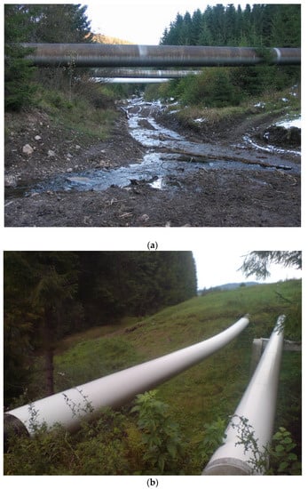
Figure 1.
Overpasses of pipelines located in the mountainous areas of the Carpathian region: (a) main gas pipeline Urengoi-Pomari-Uzhhorod; (b) Main oil pipeline Druzhba.
Therefore, when performing design or diagnostic strength calculations, one should try to consider all significant factors that affect the behavior of the overpass of the oil pipeline []. The development of new and improvement of existing methods of studying the stress–strain state of overpasses of oil pipelines are relevant applied problems, the solution of which will contribute to increasing the safety of pipeline transport.
The idea of the presented research appeared as a result of the formulation of the real industrial problem, in the solution of which the authors of the article took a direct part. As part of the implementation of the target program of the National Academy of Sciences of Ukraine, the technical diagnosis of overpasses of main oil pipelines and gas pipelines, which are in the Carpathian region and have been in operation for more than 20 years, was carried out—the most frequently identified problems related to the condition of pipeline support units. As a result of defectoscopy in the area of support nodes, along with traditional surface defects (corrosion damage, caverns, cracks, etc.), the quantitative assessment, prescribed in the expert documentation, changes in the shape of the pipe and local bulges were often recorded. The analysis of current directive documents should have allowed considering the impact of these defects on assessing the safety of further use of pipeline overpasses. It turned out that there are no such assessment methods. Our study is designed to eliminate the identified theoretical gap.
During construction and operation, oil pipelines may experience extraordinary loads [,] and be exposed to various risks []. Long-term operation of pipelines leads to damage to pipeline steel at the micro level and can contribute to the appearance of macrodefects []. The residual resource of the oil pipeline is also associated with the study of the corrosion situation []. The results of its study are used to predict the remaining service life of the pipeline. They are the reference point for establishing the cycle of inspections and the maintenance strategy []. No less important are the issues of the safe operation of underground structures in difficult mining and geological conditions [,]. The destruction of the separate section of the pipeline can lead to a catastrophic emergency, environmental problems, and significant financial losses. Therefore, for pipelines with long service life, the problems of preventing pipeline wall defects are particularly relevant []. In the field of pipeline transport, the problems of contact interaction of rod systems with the environment surrounding them have practical applications [,], as well as problems with the stiffness strength of axisymmetric structural elements, pipe columns, shells, etc. [,,,]. The demand for such research regularly arises in such areas as the construction and operation of oil and gas wells [,], the design of pipelines in karst zones [] and areas of increased seismic activity [], the construction of support columns [], the sinking of construction piles [], rational design of anti-vibration, and damping devices for long-dimension objects [,], etc.
In the process of long-term operation of oil and gas pipelines, corrosion defects in the form of significant areas of general corrosion, corrosion, and mechanical crack-like defects in the form of ulcers and caverns [,] and corrosion fatigue cracks [,] may appear on their surfaces cause a decrease in operational reliability and increase the risk of pipeline destruction. To prevent emergencies, non-destructive testing methods are used to carry out technical diagnostics of structures. As a result, sections of the oil pipeline containing both operational and technological defects are identified, and their sizes and locations are determined []. Next, it is necessary to assess the impact of the detected defects and decide on a strategy for further actions (continuation of operation, repair work, replacement of pipes, etc.). Methods of studying the stress state and structural integrity of shells damaged by closable crack-like defects were developed in papers [,]. The interference of collinear cracks in pipe material, considering the phenomenon of surface contact during bending, is studied in publications [,]. The authors [] studied the damage behavior in thin elastic shells under conditions of simultaneous stretching and bending. In addition, one of the ways to solve the problem is the application of crack healing techniques in low-carbon steel and the use of protective coatings and repair surfacing [,,].
Features of the distribution of stresses and displacements in pipeline systems have been studied in many works [,,,], and the general approaches to such problems can be divided into three global directions. The first direction is based on analytical methods [,], and the research of the second direction is based on the finite element method. It uses application packages of engineering programs [,], and the third direction uses devices for laboratory and natural measurements or model experiments [,]. Our article develops the first, analytical direction of research.
Therefore, the initiation of this study was caused by the results of the survey of the overpasses of the long-term operated oil pipelines located in the mountainous area. Defects such as the change in the shape of the pipe and local bulges in the area of the support nodes are detected. The interpretation of the described problem is separate from the typical algorithms offered to manufacturers by current directive documents. Accordingly, it is impossible to consider the impact of the detected defects on the safety of the further operation of the oil pipeline. The desire to provide an explanation and quantitative assessment of the detected defects became the main motivation to write this article.
The study aims to develop the analytical model of the interaction of the overpass pipe with the rigid support and to quantify the impact of such interaction on the strength of the oil pipeline. It is planned to develop a simple engineering technique that allows analyzing the behavior of the support node of the oil pipeline and provides the numerical correction to the traditional formulas by which the equivalent stresses are determined.
2. Materials and Methods
2.1. Modeling the Interaction of the Oil Pipeline with the Rigid Support
Consider the model of the two-section overpass of the oil pipeline in Figure 2, which is built in a mountainous area. The chosen model corresponds to the real object (see Figure 1b). The overpass consists of the above-ground section BC with the length of , equipped with the support K, and the adjacent underground sections AB and CD, which rest on the soil base (placed on the bottom of the trench). The length of the underground sections of the oil pipeline is much longer than the above-ground section. During the construction of the oil pipeline, hot-rolled seamless steel pipes were used. When considering the stress state of the oil pipeline, residual stresses that may have arisen during the manufacturing process of pipes are neglected.
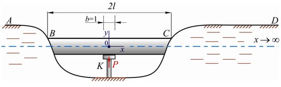
Figure 2.
The model of the two-section overpass of the oil pipeline.
The effect of volume forces and operating loads on the support K will cause a reaction P. Let us choose a pipe element of unit length above the support and consider in more detail the interaction of the selected element with the overpass support (Figure 3a). All loads that cause the reaction of the support are represented by the averaged integral equivalent q. We assume that this load q has the vertical direction and is distributed over the middle surface of the selected element of the pipe, the radius of which is R, and the wall thickness is h.
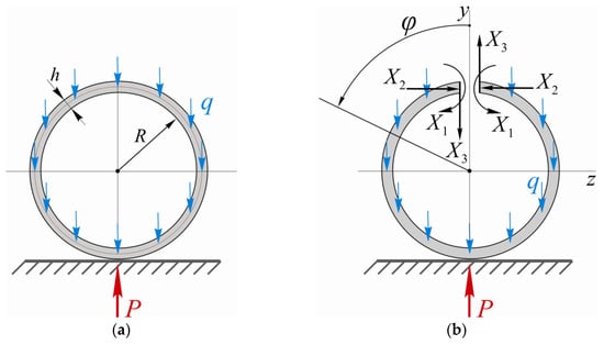
Figure 3.
The model of the interaction of the pipe with the support: (a) The scheme for analytical description of the model; (b) The equivalent scheme for revealing static indeterminacy.
The considered scheme (Figure 3a) contains the closed profile; therefore, it is statically indeterminate three times. To calculate the internal forces and stresses that arise in such a system, it is necessary to first reveal the static indeterminacy. For this, we use the method of forces. We make the vertical cut to separate the closed profile of the pipe element and apply unknown internal loads to the cut faces (Figure 3b): bending moment—X1; hoop force—X2 and transverse force—X3. The value of the loads
should be chosen so that the constructed equivalent scheme behaves like the real object. Since the selected element of the pipe is symmetrical about the vertical axis in terms of geometry and load, the transverse force is equal to zero in the selected section. To find X1 and X2, we write two equations of generalized displacements that describe the following:
- -
- the mutual angle of the rotation of the cut faces is equal to zero:
- -
- the mutual linear displacement of the cut faces is equal to zero:
We present Equations (1) and (2) in canonical form:
Here, is the specific displacement in the direction of action , which is caused by the action of the single generalized load ; is the generalized displacement in the equivalent scheme in the direction of action , which is caused by the influence of the load q.
The coefficients and free terms of Equations (3) and (4) are determined by the Maxwell–Mohr method [,]. To do this, we consider the behavior of the system shown in Figure 3b, first separately under the action of load q, then alternately under the action of unit loads and . Let us write the corresponding equations of the bending moments:
Since the model is used to evaluate objects in which the ratio of the pipe thickness to its length around the middle surface is less than 1/10, in the general equations of the Maxwell–Mohr method we limit ourselves to preserving integrals that consider only the action of bending moments, and the action of shears and compression effects are neglected.
Let us determine the components of Equations (3) and (4):
- -
- main coefficients and free terms
- -
- collateral coefficients
Here, is the Young’s modulus of the pipe material; is the length of the pipe element selected above the support.
Substituting (5) into (6) and (7), and the obtained results after integration into the displacement Equations (3) and (4), we obtain the desired result:
In this way, the static indeterminacy is revealed. Now, using the principle of superposition for linear systems, and considering the presence of the reaction P (as well as the relationship between q and P), we write the equation of bending moments for the entire circumference of the pipe (Figure 3a):
where is Heaviside’s function.
The transverse force and hoop force equations have the following form:
The distribution of internal loads in the pipe, which arise as the result of the contact interaction of the pipe with the rigid support, is illustrated in Figure 4. Here, the results are presented in dimensionless form. Thus, in Figure 4, going from top to bottom, we have: distribution of transverse forces; distribution of bending moments; and distribution of hoop forces along the length of the pipe ring.
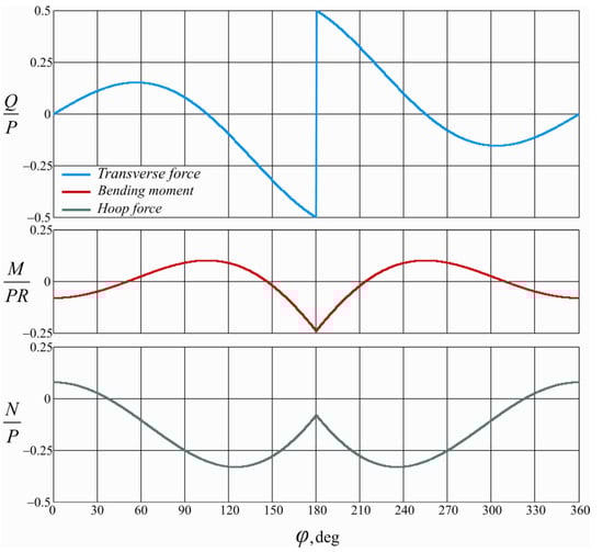
Figure 4.
The distribution of internal loads, which arise from the contact of the pipe with the support.
The transverse force Q along the length of the pipe ring varies non-monotonically, changes sign three times, and has a jump in the point of contact between the pipe and the support. The bending moment M varies non-monotonically along the length of the pipe ring has two extrema (maxima) and a pronounced corner point and reaches the highest modulus value at the point of contact of the pipe with the support. The maximum modulus value of the bending moment at stretches the inner fibers of the pipe and compresses the outer fibers. It should be noted that there is a differential relationship between graphs and . For example, the intervals, where the dependence keeps the constant sign, define areas of monotonous change in graph ; points in which , and around them the graph of transverse forces changes sign, determine the location of extrema of the graph of bending moments, etc. The hoop force N compresses in the greater part of the pipe and stretches only in a small upper area of the pipe. In contrast to the previous graphs, the maximum modulus values of the transverse force occur in sections that do not coincide with the point of contact of the pipe with the support.
Using the proposed approach, we can determine the displacement of the middle line of the pipe ring. Let us determine the change in the length of the vertical diameter of the pipe ring in the section that coincides with the y-axis (Figure 3b). To do this, we imagine applying a vertical unit force directed downwards at the point of the pipe ring with coordinates (0, 2R). The impact of such force causes the bending moment in the cross-sections of the pipe. Then, the desired displacement is as follows:
2.2. The Method to Determine the Reaction in the Intermediate Support of the Overpass of the Oil Pipeline
To use the built model of the interaction of the pipe with the support for real numerical calculations, it is necessary to determine the reaction that occurs at the support of the overpass.
Let us return to the general scheme of the overpass (Figure 2). We observed that the soil foundations to the left and to the right of the above-ground section of the oil pipeline, on which the underground sections of the structure are laid, have practically the same strength-deformation characteristics. The above-ground section consists of two identical parts and is symmetrical. Therefore, we can limit ourselves to considering half of the structure, describing and evaluating the stress–strain state of the KC and CD sections (see Figure 2). The underground section CD, laid directly on the natural soil base and loaded from above with backfill soil, was modeled by a semi-infinite beam with an annular cross-section interacting with a linear-elastic base (Figure 5). The properties of such elastic bases were described by the Fuss-Winkler hypothesis system, which allows us to assess the impact of changes in soil properties on the behavior of the oil pipeline. The above-ground part KC of the structure was modeled with an elastic tubular rod of fixed length, which has support with a one-way connection on the left end (there may be an installation gap between the support and the pipe). Standard operating loads on the oil pipeline consist of the structure’s own weight, the weight of the petroleum product filling the pipes, and the standard load from the weight of the soil used to fill the trenches with underground pipe sections. The totality of the listed force influences on the calculation scheme was presented in the form of distributed loads . At the final stage of the calculation, when assessing the strength of the oil pipeline elements, the pipes were modeled with the Kirchhoff-Love shell.
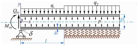
Figure 5.
The scheme for calculating the above-ground overpass of the oil pipeline with the intermediate support.
The system of differential equations of equilibrium in displacements, which describe the deformation of the oil pipeline sections, has the following form:
where , are transverse movements of the above-ground and underground sections of the oil pipeline, respectively; E is Young’s modulus of the pipe material; is the axial moment of inertia of the pipe cross-section; D is the pipe diameter; and is the bed coefficient of the soil base.
To obtain the solution of the system of Equations (11) and (12), the method of initial parameters proposed by the authors of the article in their previous publication [] was applied. As a result, we obtain the following solving equation:
where, respectively, the matrix of coefficients , the vector of free members and the vector of unknown static initial parameters have the following form:
The solution of Equation (13) gives us the value of the transverse force and the bending moment in the middle of the above-ground section, and at the beginning of the underground section are , . Then, the equations of transverse forces and bending moments for the oil pipeline can be written in the following form:
where is a coefficient that depends on the stiffness of the soil based on settlement and the bending stiffness of the oil pipeline; .
The support reaction of the oil pipeline is equal to the jump in the transverse force curve that occurs above the overpass support.
3. Results and Discussion
3.1. The Formula to Determine the Additional Hoop Stresses in the Oil Pipeline, Which Arise Due to the Interaction of the Pipe with the Support
The interaction of the oil pipeline with the support causes the occurrence of additional hoop stresses , which consists of stresses from the influence of the bending moment and stresses from the action of the hoop force :
where
Let us analyze the obtained formulas on a numerical example. We take into account that on the intermediate support of the overpass of the oil pipeline, the reaction is equal to (this value was obtained experimentally during the examination of the support node of one of the overpasses of the Druzhba oil pipeline in the Carpathians (Ukraine) [,]). The diameter of the pipe is 720 mm, and the wall thickness is 9.5 mm. Figure 6 shows the distribution of the hoop stresses that arise due to the influence of the bending moment. Stress is unevenly distributed along the pipe wall thickness. That is why Figure 6 shows two curves, that illustrate the distribution of hoop stresses in the outer (red solid line) and inner (blue dashed line) contours of the pipe cross-section. The highest modulus value of such stresses occurs in the contact area of the pipe with the support, in particular, at , , these stresses are tensile on the inner contour of the pipe cross-section and compressive on the outer contour of the cross-section pipe.
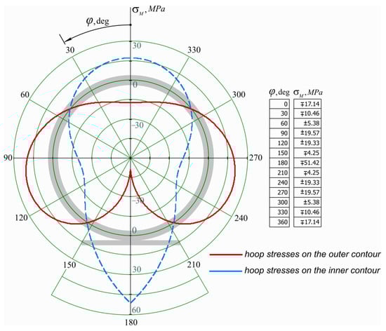
Figure 6.
The distribution of hoop stresses that arise due to the interaction of the oil pipeline with the support (caused by the bending moment).
Figure 7 shows the distribution of the hoop stresses , which arise due to the influence of the hoop force. These stresses are evenly distributed throughout the thickness of the pipe, and in most of the pipe they are compressive, only in the small upper area of the pipe are these stresses tensile. The maximum modulus values occur in cross-sections that do not coincide with the point of contact of the pipe with the support (at and , ). If we compare the absolute values of stresses and , then obviously have a significantly smaller effect on the strength of the pipe material.
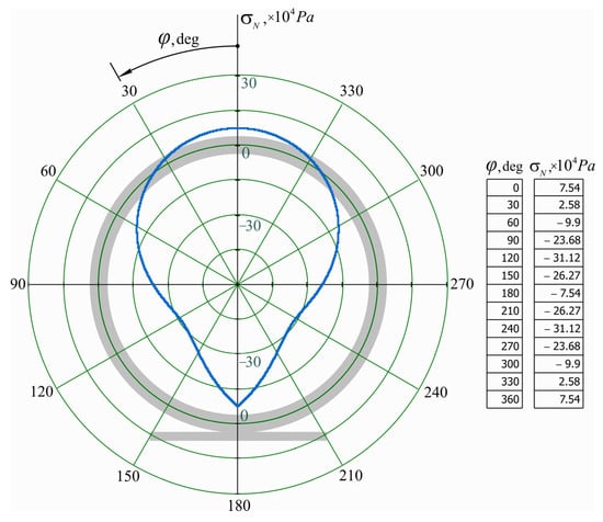
Figure 7.
The distribution of hoop stresses that arise due to the interaction of the oil pipeline with the support (caused by the hoop force).
Figure 8 illustrates the effect of the ratio of the pipe’s radius to the wall thickness on the value of the additional hoop stresses. The greater the ratio , the greater the additional hoop stresses caused by the interaction of the pipe with the support, other things being equal.
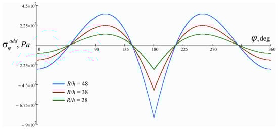
Figure 8.
The influence of the ratio of the pipe’s radius to the wall thickness on the value of additional hoop stresses that arise due to the interaction of the oil pipeline with the support.
The normal pressure in the oil pipeline creates operational hoop tensile stresses in the pipe material. Therefore, the additional tensile stresses, which add up to the standard stresses, harm the strength of the oil pipeline. Analysis of Formulas (17)–(19) and graphs in Figure 6, Figure 7 and Figure 8 allow us to do the following conclusion. As a result of the interaction of the oil pipeline with the support, the maximum tensile stresses occur on the inner contour of the pipe cross-section in the contact area. These stresses can be determined by the following formula:
The greater the ratio , the higher the convergence of the results obtained by the exact and approximate variants of Formula (20).
3.2. Analysis of the Strength of the Overpass of the Oil Pipeline in the Contact Area with the Intermediate Support
As a result of the influence of operational loads, the complex stress state occurs in the material of the oil pipeline. At this research stage, we model the oil pipeline with the Kirchhoff–Leav thin-walled shell, and we use the Huber–Mises theory to evaluate the strength. According to this theory, the strength criterion is the amount of specific potential deformation energy accumulated by a deformed structural element. The expression for determining the equivalent stresses in the oil pipeline will have the following form [,]:
Here, the normal stresses in the top and bottom fibers of the oil pipeline will be determined based on the presence of a flat thermoelastic stress–strain state:
where is hoop stresses in the pipe from the influence of the pressure of the petroleum product being pumped, represents stresses that can be caused by temperature changes, represents normal stresses that arise as a result of pipe bending, p is the pressure of the petroleum product being pumped, is coefficient of thermal expansion for pipe material, is change in oil pipeline temperature, is Poisson’s ratio, is the function of the bending moment distribution along the length of the overpass of the oil pipeline (determined by Formula (16)).
However, to estimate the strength of the pipe in the contact area of the overpass of the oil pipeline with the intermediate support, Formula (21) must be supplemented with the component determined by Equation (20). The specified formula for determining the equivalent stresses in the area of the support node of the oil pipeline is as follows:
Since the phenomenon of the occurrence of additional hoop stresses occurs only in the area of contact of the oil pipeline with the support, i.e., it has an exclusively local character, the term in Equation (22) is still missing.
To ensure the strength of the structure, it is necessary to perform the strength conditions: on the section of the overpass and adjacent underground sections ; in the area of the support node , where is the permissible stress for the material of the structure, taking into account the reserve coefficients, working conditions, reliability, etc., which are regulated by current directive documents.
Let us illustrate what is described in the example of the specific problem. Figure 1b shows the general appearance of the overpass of the oil pipeline, which is built in the mountainous area of the Carpathian region. For this research, we chose the two-section overpass (shown on the right in Figure 1b). The total length of the overpass is 25 m, while the intermediate support is built in the middle of the overpass, which divides the overpass into two sections 12.5 m long. The support design allows, if necessary, to create the installation gap in the support node. The underground sections of the oil pipeline are laid directly on the natural soil base, which is represented by dispersed cohesive rock, that is loam. For loam, the bedding coefficient was determined by field tests. The underground sections of the overpass are deepened by and filled with soil that has a specific gravity . The material of the pipe is tubular steel with the following mechanical characteristics: elasticity modulus is , Poisson’s ratio is 0.3, and yield strength is . The required geometric characteristics of the pipes: the diameter is , and the wall thickness is . The pipeline is used to transport crude oil, and the average operating pressure is , the temperature difference was considered insignificant. Distributed loads are and , which were applied to the calculation model (Figure 5) were calculated according to normative methods [].
Figure 9 shows graphs of internal loads (transverse forces and bending moments) that occur in the oil pipeline. Such graphic dependencies indirectly describe the stressed state of the structure. The graphs are presented in the Cartesian coordinate system, the origin of which is aligned with the middle of the above-ground section (see Figure 2). Therefore, the graphs show the internal loads in the above-ground section of the oil pipeline at , and the internal loads in the underground section of the oil pipeline at . To draw such dependencies, the sequence of actions is as follows. It is necessary to first use Equation (13) and calculate the vector of unknown static initial parameters. For example, for case 2, when there is a gap in the support node, from Equation (13) we obtain: , , , and . After that, Equations (15) and (16) should be used alternately.
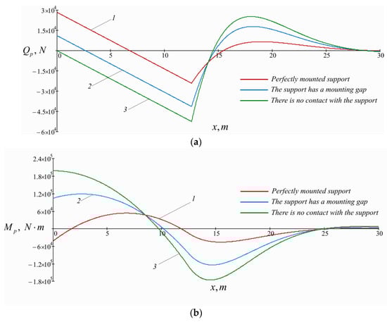
Figure 9.
Distribution of internal forces in the above-ground () and underground () sections of the oil pipeline: (a) distribution of transverse forces along the length of the oil pipeline; (b) distribution of bending moments along the length of the oil pipeline (the graphs are drawn from the side of the compressed fibers of the oil pipeline); 1—perfectly mounted support; 2—support has the mounting gap; 3—there is no contact between the oil pipeline and the support.
In the case of the ideal installation of the intermediate support, we get the largest value of the support reaction and the smallest value of the bending moments in the oil pipeline. As the mounting gap increases, the support reaction gradually decreases, and the absolute values of the bending moments in the oil pipeline increase. If there is no contact between the pipe and the intermediate support, there is no support reaction, and the bending moments in the oil pipeline acquire the greatest values.
A characteristic feature of the presented dependences (Figure 9) is the wave-like changes in the functions of internal loads at the beginning of the underground section of the oil pipeline with gradual damping when moving away from the edge of this section. We call such an effect the marginal effect of the change in the stress state of the underground section of the oil pipeline, and the length over which this effect has significant manifestations is the length of the marginal effect. The damping of the marginal effect is explained by the presence in Equations (15) and (16) of the functions , which contain the multiplier . This multiplier goes to zero if the product goes to infinity. Let us estimate the length of the marginal effect for the considered case using the function . If , then this function is equal to one. If , then , therefore, with an accuracy of up to 5%, the function can be considered already damped. From the equality , we calculate that for the underground section of the oil pipeline, the marginal effect has significant manifestations along the length , therefore, the construction of graphs can be limited to the coordinate .
Let us evaluate the strength of the support node of the oil pipeline in case 2 (Figure 9). According to the classical formula for equivalent stresses (21), we get . The additional hoop stresses that arise from the contact of the pipe with the support are calculated by Formula (20), and we get . Specified Formula (23) for calculating the maximum equivalent stresses in the support node gives the result . Let’s consider the construction of the overpass of the oil pipeline in general. The support node is a concentrator of equivalent stresses, and the ratio can be considered a theoretical coefficient of concentration of equivalent stresses in the support node. For the considered case, the limit state does not occur, since the equivalent stresses do not exceed the yield point of the pipe material.
Figure 10 is illustrated the distribution of the maximum equivalent stresses in the overground and underground sections of the oil pipeline in general. Graphical dependence 1 (shown in Figure 10 by a solid red line) is constructed for the case when the oil pipeline is laid on the intermediate support without the installation gap. For its construction, Formula (21) was used, which does not consider the influence of the contact interaction of the pipe with the support on the stressed state of the structure. Graphical dependence 2 (shown in Figure 10 by a solid green line) is constructed for when the oil pipeline does not come into contact with the intermediate support. A comparison of curves 1 and 2 shows that intermediate support reduces the maximum equivalent stresses in the oil pipeline. Under other identical conditions, the limit state of the oil pipeline will come sooner for the second case and will be reached first at a distance of about 1.3 m from the edge of the underground section. However, after applying the refined Formula (23) and drawing graphic dependence 3 (presented in Figure 10 by a red dashed line, which later coincides with curve 1), there is a sharp increase in the equivalent stresses in the area of the support node. Such the sharp perturbation of the equivalent stresses has a local character because when moving away from the center of the support node, the equivalent stresses decrease rapidly. Nevertheless, it should be remembered that the destruction of the separate (even the small) section of the oil pipeline can lead to a facility-wide emergency; therefore, when assessing the strength, it is necessary to take into account the influence of the interaction of the pipe with the support on the value of the equivalent stresses.
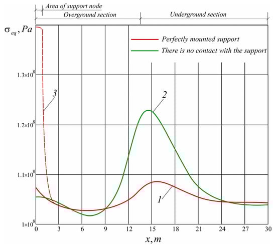
Figure 10.
Distribution of the maximum equivalent stresses in the overground and underground sections of the oil pipeline: 1—the oil pipeline is laid on the intermediate support without the installation gap, and calculations are made according to Formula (21); 2—the oil pipeline does not come into contact with the intermediate support, calculations are made according to Formula (21); 3—the oil pipeline is laid on the intermediate support without the installation gap, calculations are made according to the refined Formula (23).
It should be noted that the internal loads in the oil pipeline depend on several factors, among which is the bed coefficient of the soil base of the underground sections. When checking overpass, this coefficient must be determined for a specific research object.
The properties of the base for laying overpass pipes differ depending on the terrain, and the depth of the trench. The resistance to the pipe movement of the same soil type can even vary significantly depending on the season or weather conditions. Today, in several mountainous regions, abnormal climate changes (uncharacteristic for these areas) are occurring, which cause unfavorable physical and geographical processes (slides, waterlogging, flooding, etc.). In these cases, considering extraordinary changes in the compliance of the soil base on the strength of the transition will have an important diagnostic value.
4. Conclusions
Many factors affect the safe operation of overpasses of main oil pipelines, one of which is the contact interaction of the pipe with rigid supports. Particularly significant changes in the process of long-term operation occur in the pipeline precisely in the areas of support nodes. Therefore, during diagnostic inspections of the overpasses, special attention should be paid to the areas of contact between the pipe and the supports, and conclusions regarding the safety of further operation of the structure should be based on detailed strength calculations.
This study has three main innovation outcomes as follows:
- An analytical model of the interaction of the overpass of the pipeline with the rigid support has been developed. The developed model makes it possible to determine additional internal loads in the pipe and displacement of its middle surface, which occur due to the contact of the pipe with the support.
- The method of determining the reaction in the intermediate support of the overpass of the oil pipeline has been developed, which considers the influence on the reaction value of the properties of the soil base of the underground sections of the overpass and the possible presence of the installation gap in the support node.
- The analytical dependence was obtained to determine the additional hoop stresses in the oil pipeline, which arise due to the contact of the pipe with the support. The unambiguous relationship between the maximum additional hoop stress and the reaction in the support node is established.
Therefore, in order to use the results of the conducted research, it is necessary to perform the following sequence of actions. Using the method of initial parameters, we solve Equation (13) and calculate the reaction at the support node we are interested in. The maximum value of additional hoop stresses, which arise from the contact interaction of the pipe surface with the support, is determined by Formula (20). We formulate the strength condition of the oil pipeline as a thin-walled shell, using the Huber–Mises energy strength criterion—Expression (21) while considering the two-dimensional thermoelastic state of the oil pipeline, the normal stress in its extreme fibers is determined by Formula (22). Finally, we calculate the maximum equivalent stresses in the zones of the support nodes of the oil pipeline according to the refined Formula (23), which considers the effect of additional hoop stresses on the strength.
The obtained research results were tested on the real structure of the overpass of the oil pipeline built in the mountainous area. In general, the study’s results represent the engineering theory that allows analyzing the behavior of the support node of the oil pipeline and provides the numerical correction to traditional formulas for strength estimation. In further research, it is expedient to study the influence of seismic loads, which often occur in mountainous areas, on the strength of the support nodes of overpasses of oil pipelines.
Author Contributions
Conceptualization, M.D. and A.V.; methodology, M.D., A.A., I.P. and A.K.; software, A.A.; validation, M.D., A.V. and A.A.; formal analysis, I.P. and A.K.; investigation, M.D. and A.V.; resources, A.A., I.P. and A.K.; data curation, M.D. and A.A.; writing—original draft preparation, A.V. and M.D.; writing—review and editing, M.D. and A.V.; visualization, A.V. and M.D.; supervision, A.A., I.P. and A.K.; project administration, M.D. and A.V.; funding acquisition, M.D. and A.V. All authors have read and agreed to the published version of the manuscript.
Funding
This research received no targeted external funding.
Data Availability Statement
Data are contained within the article.
Conflicts of Interest
The authors declare no conflict of interest.
References
- IEA. World Energy Outlook. Flagship Report—2022; International Energy Agency: Paris, France, 2022; Available online: https://www.iea.org/reports/world-energy-outlook-2022 (accessed on 9 May 2023).
- Simão, M.; Mora-Rodriguez, J.; Ramos, H.M. Design Criteria for Suspended Pipelines Based on Structural Analysis. Water 2016, 8, 256. [Google Scholar] [CrossRef]
- Mohamed Azzam, M. Failure Analysis of Pipelines in the Oil and Gas Industry. In Pipeline Engineering—Design, Failure, and Management; IntechOpen: London, UK, 2023. [Google Scholar] [CrossRef]
- Popescu, C.; Gabor, M.R. Quantitative Analysis Regarding the Incidents to the Pipelines of Petroleum Products for an Efficient Use of the Specific Transportation Infrastructure. Processes 2021, 9, 1535. [Google Scholar] [CrossRef]
- Dai, L.; Wang, D.; Wang, T.; Feng, Q.; Yang, X. Analysis and Comparison of Long-Distance Pipeline Failures. J. Pet. Eng. 2017, 2017, 3174636. [Google Scholar] [CrossRef]
- Xie, M.; Tian, Z. A review on pipeline integrity management utilizing in-line inspection data. Eng. Fail. Anal. 2018, 92, 222–239. [Google Scholar] [CrossRef]
- Velychkovych, A.S.; Andrusyak, A.V.; Pryhorovska, T.O.; Ropyak, L.Y. Analytical model of oil pipeline overground transitions, laid in mountain areas. Oil Gas Sci. Technol. 2019, 74, 65. [Google Scholar] [CrossRef]
- Kryzhanivs’kyi, E.I.; Rudko, V.P.; Shats’kyi, I.P. Estimation of admissible loads upon a pipeline in the zone of sliding ground. Mater. Sci. 2004, 40, 547–551. [Google Scholar] [CrossRef]
- Amandi, K.U.; Diemuodeke, E.O.; Briggs, T.A. Model for remaining strength estimation of a corroded pipeline with interacting defects for oil and gas operations. Cogent Eng. 2019, 6, 1663682. [Google Scholar] [CrossRef]
- Bembenek, M.; Mandziy, T.; Ivasenko, I.; Berehulyak, O.; Vorobel, R.; Slobodyan, Z.; Ropyak, L. Multiclass Level-Set Segmentation of Rust and Coating Damages in Images of Metal Structures. Sensors 2022, 22, 7600. [Google Scholar] [CrossRef]
- Bi, A.; Huang, S.; Zhang, Y.; Gao, Y. Reliability Analysis of Oil and Gas Pipelines Based on Step-Down-Stress Testing in Corrosive Environments. Math. Probl. Eng. 2022, 2022, 4055779. [Google Scholar] [CrossRef]
- Dutkiewicz, M.; Shatskyi, I.; Martsynkiv, O.; Kuzmenko, E. Mechanism of Casing String Curvature Due to Displacement of Surface Strata. Energies 2022, 15, 5031. [Google Scholar] [CrossRef]
- Shats’kyi, I.P.; Struk, A.B. Stressed state of pipeline in zones of soil local fracture. Strength Mater. 2009, 41, 548–553. [Google Scholar] [CrossRef]
- Dutkiewicz, M.; Dalyak, T.; Shatskyi, I.; Venhrynyuk, T.; Velychkovych, A. Stress Analysis in Damaged Pipeline with Composite Coating. Appl. Sci. 2021, 11, 10676. [Google Scholar] [CrossRef]
- Shatskii, I.P.; Perepichka, V.V. Shock-wave propagation in an elastic rod with a viscoplastic external resistance. J. Appl. Mech. Tech. Phys. 2013, 54, 1016–1020. [Google Scholar] [CrossRef]
- Shatskyi, I.; Vytvytskyi, I.; Senyushkovych, M.; Velychkovych, A. Modelling and improvement of the design of hinged centralizer for casing. IOP Conf. Ser. Mater. Sci. Eng. 2019, 564, 12073. [Google Scholar] [CrossRef]
- Bazaluk, O.; Dubei, O.; Ropyak, L.; Shovkoplias, M.; Pryhorovska, T.; Lozynskyi, V. Strategy of Compatible Use of Jet and Plunger Pump with Chrome Parts in Oil Well. Energies 2022, 15, 83. [Google Scholar] [CrossRef]
- Shats’kyi, I.P. Closure of a longitudinal crack in a shallow cylindrical shell in bending. Mater. Sci. 2005, 41, 186–191. [Google Scholar] [CrossRef]
- Panevnik, D.A.; Velichkovich, A.S. Assessment of the stressed state of the casing of the above-bit hydroelevator. Neft. Khozyaystvo Oil Ind. 2017, 1, 70–73. [Google Scholar]
- Velichkovich, A.S. Shock Absorber for Oil-Well Sucker-Rod Pumping Unit. Chem. Petrol. Eng. 2005, 41, 544–546. [Google Scholar] [CrossRef]
- Grydzhuk, J.; Chudyk, I.; Velychkovych, A.; Andrusyak, A. Analytical estimation of inertial properties of the curved rotating section in a drill string. East. Eur. J. Enterp. Technol. 2019, 1, 6–14. [Google Scholar] [CrossRef]
- Velychkovych, A.; Petryk, I.; Ropyak, L. Analytical study of operational properties of a plate shock absorber of a sucker-rod string. Shock. Vib. 2020, 2020, 3292713. [Google Scholar] [CrossRef]
- Wu, N.; Liu, Y.; Tong, G.; Dai, J. Stability Analysis of Multispan Pipeline Embedded in Temperature-Dependent Matrix. Math. Probl. Eng. 2021, 2021, 6153291. [Google Scholar] [CrossRef]
- Han, B.-J.; Jiang, Y.-S.; Wang, Z.; Gong, D.; Jiang, H.; Jiang, P. Analysis of the Risk Path of the Pipeline Corridor Based on System Dynamics. Shock. Vib. 2021, 2021, 5529642. [Google Scholar] [CrossRef]
- Velychkovych, A.; Ropyak, L.; Dubei, O. Strength Analysis of a Two-Layer PETF-Concrete Column with Allowance for Contact Interaction between Layers. Adv. Mater. Sci. Eng. 2021, 2021, 4517657. [Google Scholar] [CrossRef]
- Shatskyi, I.; Perepichka, V. Problem of dynamics of an elastic rod with decreasing function of elastic-plastic external resistance. In Dynamical Systems in Applications, Proceedings of the DSTA 2017, Lodz, Poland, 11–14 December 2017; Awrejcewicz, J., Ed.; Springer: Cham, Switzerland, 2018; Volume 249, pp. 335–342. [Google Scholar] [CrossRef]
- Shatskyi, I.; Velychkovych, A. Analytical Model of Structural Damping in Friction Module of Shell Shock Absorber Connected to Spring. Shock. Vib. 2023, 2023, 4140583. [Google Scholar] [CrossRef]
- Dutkiewicz, M.; Velychkovych, A.; Shatskyi, I.; Shopa, V. Efficient Model of the Interaction of Elastomeric Filler with an Open Shell and a Chrome-Plated Shaft in a Dry Friction Damper. Materials 2022, 15, 4671. [Google Scholar] [CrossRef] [PubMed]
- Xie, M.; Wang, Y.; Xiong, W.; Zhao, J.; Pei, X. A Crack Propagation Method for Pipelines with Interacting Corrosion and Crack Defects. Sensors 2022, 22, 986. [Google Scholar] [CrossRef]
- Vanaei, H.R.; Eslami, A.; Egbewande, A. A review on pipeline corrosion, in-line inspection (ILI), and corrosion growth rate models. Int. J. Press. Vessel. Pip. 2017, 149, 43–54. [Google Scholar] [CrossRef]
- Du, J.; Wang, H.; Wang, S.; Song, X.; Wang, J.; Chang, A. Fatigue damage assessment of mooring lines under the effect of wave climate change and marine corrosion. Ocean. Eng. 2020, 206, 107303. [Google Scholar] [CrossRef]
- Jimenez-Martinez, M. Harbor and coastal structures: A review of mechanical fatigue under random wave loading. Heliyon 2021, 7, E08241. [Google Scholar] [CrossRef]
- Velázquez, J.C.; Hernández-Sánchez, E.; Terán, G.; Capula-Colindres, S.; Diaz-Cruz, M.; Cervantes-Tobón, A. Probabilistic and Statistical Techniques to Study the Impact of Localized Corrosion Defects in Oil and Gas Pipelines: A Review. Metals 2022, 12, 576. [Google Scholar] [CrossRef]
- Shats’kyi, I.P.; Makoviichuk, M.V. Analysis of the limiting state of cylindrical shells with cracks with regard for the contact of crack lips. Strength Mater. 2009, 41, 560–565. [Google Scholar] [CrossRef]
- Rong, L.; Tie, Z.; Wu, X.J.; Wang, C.H. Crack closure effect on stress intensity factors of an axially and a circumferentially cracked cylindrical shell. Int. J. Fract. 2004, 125, 227–248. [Google Scholar] [CrossRef]
- Shatskii, I.P.; Makoviichuk, N.V. Effect of closure of collinear cracks on the stress-strain state and the limiting equilibrium of bent shallow shells. J. Appl. Mech. Tech. Phys. 2011, 52, 464–470. [Google Scholar] [CrossRef]
- Dovbnya, K.M.; Hryhorchuk, Y.V. Stressed state of a shell of double curvature with two collinear cracks under bending. J. Math. Sci. 2016, 212, 98–105. [Google Scholar] [CrossRef]
- Shats’kyi, I.P.; Makoviichuk, M.V. Contact interaction of crack lips in shallow shells in bending with tension. Mater. Sci. 2005, 41, 486–494. [Google Scholar] [CrossRef]
- He, M.; Zhentai, Z.; Shi, F.; Guo, D.; Yu, J. A novel crack healing technique in a low carbon steel by cyclic phase transformation heat treatment: The process and mechanism. Mater. Sci. Eng. A 2020, 772, 138712. [Google Scholar] [CrossRef]
- Prysyazhnyuk, P.; Molenda, M.; Romanyshyn, T.; Ropyak, L.; Romanyshyn, L.; Vytvytskyi, V. Development of a hardbanding material for drill pipes based on high-manganese steel reinforced with complex carbides. Acta Montan. Slovaca 2022, 27, 685–696. [Google Scholar] [CrossRef]
- Bembenek, M.; Prysyazhnyuk, P.; Shihab, T.; Machnik, R.; Ivanov, O.; Ropyak, L. Microstructure and Wear Characterization of the Fe-Mo-B-C—Based Hardfacing Alloys Deposited by Flux-Cored Arc Welding. Materials 2022, 15, 5074. [Google Scholar] [CrossRef]
- Xu, P.; Zhang, M.; Lin, Z.; Cao, Z.; Chang, X. Additional Stress on a Buried Pipeline under the Influence of Coal Mining Subsidence. Adv. Civ. Eng. 2018, 2018, 3245624. [Google Scholar] [CrossRef]
- Feng, Q.; Li, R.; Zhang, H. Modeling and Calculation of Dent Based on Pipeline Bending Strain. J. Sens. 2016, 2016, 8126214. [Google Scholar] [CrossRef]
- Wang, X.; Li, H.; Li, B.; Sheng, J.; Zhao, J.; Ding, Y.; Lu, D. Simulation Analysis of External Damage and Repair of the Gas Transmission Pipeline. Adv. Mater. Sci. Eng. 2022, 2022, 3978649. [Google Scholar] [CrossRef]
- Li, X.; Wu, Q.; Jin, H.; Kan, W. A New Stress Monitoring Method for Mechanical State of Buried Steel Pipelines under Geological Hazards. Adv. Mater. Sci. Eng. 2022, 2022, 4498458. [Google Scholar] [CrossRef]
- Zhang, W.; Zhang, J.; Li, X.; Chen, F.; Guo, J.; Li, W.; Cai, J. Energy pipeline strength evaluation and reliability technology based on Fuzzy deep learning network algorithm. Energy Rep. 2022, 8, 5129–5136. [Google Scholar] [CrossRef]
- Witek, M. Structural Integrity of Steel Pipeline with Clusters of Corrosion Defects. Materials 2021, 14, 852. [Google Scholar] [CrossRef] [PubMed]
- Tan, N.; Zhou, L.; Zheng, W.; Song, H.; Sun, Z.; Wang, Z.; Wang, G.; Wang, G.; Zhang, L.; Zhou, X. Using Finite Element Method for Stress-Strain Evaluation of Commonly Used Buried Pipelines in Fault. Energies 2022, 15, 1655. [Google Scholar] [CrossRef]
- Liu, X.; Sun, Z.; Zhu, J.; Fang, Y.; He, Y.; Pan, Y. Study on Stress-Strain Characteristics of Pipeline-Soil Interaction under Ground Collapse Condition. Geofluids 2022, 2022, 5778761. [Google Scholar] [CrossRef]
- Li, L.; Ma, H.; Jing, H. Vertical Displacement Monitoring and Safety Evaluation of Oil Pipelines in Permafrost Region. J. Geosci. Environ. Prot. 2018, 6, 247–256. [Google Scholar] [CrossRef]
- Abushanab, W. Oil Transmission Pipelines Condition Monitoring Using Wavelet Analysis and Ultrasonic Techniques. Engineering 2013, 5, 551–555. [Google Scholar] [CrossRef]
- Lee, D.; Shin, S.; Hoan Doan, Q. Real-time robust assessment of angles and positions of nonscaled steel outrigger structure with Maxwell-Mohr method. Constr. Build. Mater. 2018, 186, 1161–1176. [Google Scholar] [CrossRef]
- Dubei, O.Y.; Tutko, T.F.; Ropyak, L.Y.; Shovkoplias, M.V. Development of Analytical Model of Threaded Connection of Tubular Parts of Chrome-Plated Metal Structures. Metallofiz. Noveishie Tekhnol. 2022, 44, 251–272. [Google Scholar] [CrossRef]
- Kychma, A.O.; Predko, R.Y. Estimation of residual stresses for multi-layer circumferential welds of oil and gas pipelines. Diagnostyka 2019, 20, 11–18. [Google Scholar] [CrossRef]
- Banakhevych, Y.V.; Dragilev, A.V.; Kychma, A.O. Diagnostics of the Stress-Strain State of Multilayer Annular Welded Joints of Pipelines. Mater. Sci. 2014, 50, 217–223. [Google Scholar] [CrossRef]
- Shats’kyi, I.P.; Shopa, V.M.; Velychkovych, A.S. Development of full-strength elastic element section with open shell. Strength Mater. 2021, 53, 277–282. [Google Scholar] [CrossRef]
- Tutko, T.; Dubei, O.; Ropyak, L.; Vytvytskyi, V. Determination of Radial Displacement Coefficient for Designing of Thread Joint of Thin-Walled Shells. In Advances in Design, Simulation and Manufacturing IV, Proceedings of the 4th International Conference on Design, Simulation, Manufacturing: The Innovation Exchange, DSMIE 2021, Lviv, Ukraine, 8–11 June 2021; Ivanov, V., Trojanowska, J., Pavlenko, I., Zajac, J., Peraković, D., Eds.; Lecture Notes in Mechanical Engineering; Springer: Cham, Switzerland, 2021; pp. 153–162. [Google Scholar] [CrossRef]
- Singh, R. Pipeline Integrity Handbook: Management and Risk Evaluation; Elsevier Science: Amsterdam, The Netherlands, 2017. [Google Scholar]
Disclaimer/Publisher’s Note: The statements, opinions and data contained in all publications are solely those of the individual author(s) and contributor(s) and not of MDPI and/or the editor(s). MDPI and/or the editor(s) disclaim responsibility for any injury to people or property resulting from any ideas, methods, instructions or products referred to in the content. |
© 2023 by the authors. Licensee MDPI, Basel, Switzerland. This article is an open access article distributed under the terms and conditions of the Creative Commons Attribution (CC BY) license (https://creativecommons.org/licenses/by/4.0/).