1. Introduction
Currently, the demand for energy worldwide is constantly increasing and technologies based on fossil fuels are used to meet the requirements of modern society. In this sense, the excessive use of fossil fuels has produced consequences and irreversible damage to the environment. The waste pollution gases by combustion are the main factor that contribute to global warming, causing an increase in global temperature, and consequently, an irreversible deterioration of the environment and its ecosystems.
The use of renewable technologies to produce energy is an alternative to reduce this destructive trend. In this sense, solar energy has the potential to meet the needs of global energy demand because is an inexhaustible, abundant, reliable, and clean resource. Mitigating the global warming by the substitution of fossil fuel power by solar power will be, in a short time, environmentally, economically, and socially beneficial to the entire world. A constant effort to implement solar energy technologies will result in a beneficial reduction in CO
2 emissions by 2050, while on the other hand, the non-implementation of sustainable energies will jeopardize the future of the planet [
1,
2,
3,
4].
In this sense, a point that has recently become of interest in the scientific community is the combination of traditional power plants and the application of solar technology. The result has been the hybridization of power plants that use a traditional combined cycle with solar technology (ISCC). Mainly, the solar technology is the PTC, one of the most mature devices to convert the incident solar irradiation into sensible heat by heating a working fluid with a high operating temperature range, normally up to 300 °C [
4,
5].
PTC technology is highly efficient, even at elevated levels of temperature, and are widely used in ISCC power plants; moreover, PTC technology is capable of directly generating steam (DSG), resulting in an increment in the affordability of the power plant. The sizing and optimization of an ISCC-PTC-DSG is extremely important because of the cost investment. Therefore, it is important to have reliable tools and procedures to thermally evaluate and predict the behavior and performance of such power plants [
6].
For example, a study that looked at predicting the performance of an ISSC-PTC installed in Aswan City, Egypt demonstrated that the plant capacity increased by 50 MW in the summer months, having an annual reduction in gas emissions close to 51,670.8 tons [
4]. The authors used Mathcad models, Excel, and Water Steam Pro to analyze the thermodynamic performance of the plant.
The Kurymat power plant, installed at South Cairo, Egypt, uses the PTC technology to generate the steam during the daytime. The plant was modeled and numerically simulated using the TRNSYS software and the results were compared with the measured data of the power plant and the numerical results were in close agreement with the measurements [
7].
The application of PTC combined with a steam Rankine, an organic Rankine cycle with the capacity to store heat for operating when solar irradiance is not present, was analyzed by means of multi-objective optimization using the PSO algorithm with the addition of EES and MATLAB. The PSO algorithm selects the best designing variables, and the results showed that 59% of the total exergy destruction happens on the solar collector [
8].
A model based on an energy balance in PTC collectors was used to determine the main operative parameters of a typical power plant. The simulation considered forced convection inside the solar absorber tube and the model was verified using heat data from a solar thermal power plant located in Spain. The heat generated in similar conditions of a solar collector in the region with a temperate climate in the city of Bialystok, Poland was determined by the model for different months of the year. The results showed that the energy obtained from the same area of concentrated solar collectors was eight times lower compared to the installation in Spain [
9].
Another work investigated the performance of a conventional steam power plant retrofitted with a solar-assisted regenerative system using parabolic trough solar collectors, where the steam power plant was located in Kuwait, which received high solar radiation levels. The results showed that removing the low-pressure turbine extractions enhanced the performance of the solar power plant by 9.8 MW with an aperture area of
, a techno-economic analysis was also used to estimate the levelized cost of energy; this power plant, compared to a conventional photovoltaic solar plant, reduced the total aperture area to 45% and 44% [
10].
Different numerical tools such as TRNSYS-STEC, GateCycle, Termoflex, SAM, models in MATLAB, CYCLO-Tempo, TRNSYS, mathematical models in FORTRAN, IPSEpro, models in Mathcad, PSO with EES and MATLAB, just to mention a few, have been used to predict the behavior and performance of ISCC-PTC-DSG power plants [
5]. However, none of them were based on the theory of phase change in the PTC as the software presented here does.
In this paper, the thermal evaluation of a solar power plant by means of a numerical tool for evaluating DSG with PTC technology was developed. The software offers the user the possibility of comparing the thermal behavior of different geometrical dimensions for a PTC and even considers different materials to satisfy the demand of superheated steam by a DSG process. The objective was to use this novel numerical tool to analyze the feasibility of implementing ISCC-PTC-DSG in substituting the actual configuration of a CC power plant in Mexico that uses a PTC field with a synthetic oil as the heat transfer substance.
3. Mathematical Model
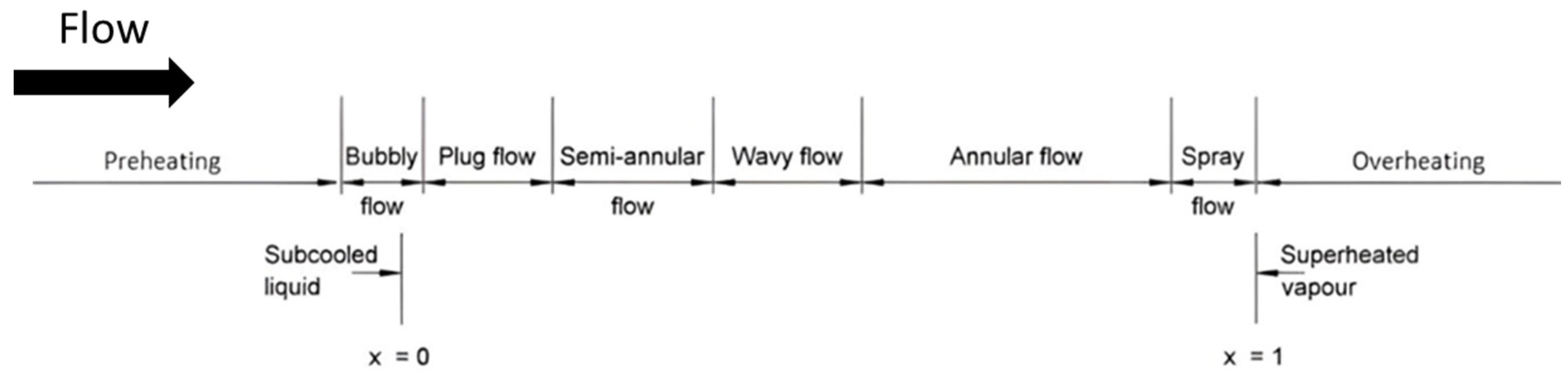
DSG generation based on parabolic trough solar collectors can be simplified for analysis by considering them as horizontal pipes with a constant heat flux at the outer boundary, while in the interior, a forced evaporation phenomenon is developing. The evaporative process can be divided into three different heating zones: saturated liquid where the temperature is less than the saturation liquid temperature when the fluid enters the absorber, then the steam generation zone where the fluid goes through several flow patrons until reaching the saturated steam condition. Finally, there is the reheating zone, where the steam reaches the desired steam condition. In the first and last heating zones, the HTF will be considered as a one phase fully developed fluid. The HTF goes into the collector as a subcooled fluid and when passing through the collector, the fluid temperature and wall temperature increase in the flow direction, and the mean temperature can be computed by means of an energy balance in the axial direction. Similarly, once the HTF has become steam, it will be treated as a one phase fluid. This zone is critical because as the heat flux remains constant at the boundary, and the sudden diminution in the heat transfer coefficient carries a sudden increase in the wall temperature, which can cause severe damage in the duct. Several studies have considered that this critical situation is because the liquid film in the annular regime has evaporated because of the heating flux conditions in the wall [
13].
In zones 1 and 3, the heat transfer coefficient will be computed using the classical model for a fully developed flow in one phase for circular pipes. The heat transfer coefficient for fully developed flow in pipes depends on the flow regime and in the heat imposed on the pipe wall as the boundary. For the turbulent regime, the Nusselt is a function of the Reynolds, the Prandtl, and the friction factor. Gnielinski developed a correlation valid for several Reynolds including the transition zone with a maximum of 10% error when compared with the experimental data [
14].
In the evaporative zone or changing phase zone, the liquid and steam are at saturation conditions and the heat at the wall produces the latent thermal energy for the evaporation process. Here, the assumptions of a horizontal smooth pipe will be applied. The flow patterns and the heat transfer are a function of the temperature differences between the wall and the fluid saturation temperature as well as the fluid properties.
The heat radiant energy supplied is captured by the receiver pipe, which induces changes in the flow going from a saturated liquid to a saturated steam. The flow goes through different patterns [
15], as shown in
Figure 1. As the mass flow is higher, the flow pattern is more symmetric and stable, which occurred in the vertical ducts. In this sense, a high mass flow would be recommended by the PTC operation.
There are several correlations in the literature related to the evaporative forced convective heat transfer. Chen’s correlation is the most widely used when water is considered; this correlation uses more than 600 experimental data for water in a vertical duct [
16]. The approximation is good for water at low pressure but is not suitable for thermal oils or refrigerants. Gunger and Winterton combined the models of Chen and Shah, while Liu and Winterton showed a correlation based on more than ten thousand data for water, refrigerants, and cryogenic substances [
13,
17,
18]. These data are suitable for a large variety of density relations for the liquid and vapor phases as well as different heat flux and mass flows. The effect of density and boiling number are critical for the computation. He presented a simple model for the convective effects and the nucleation by introducing an additional parameter for taking into account the effects of the fluid surface and the nucleate boiling dominant region and the convective boiling dominant region based on the convective number, boiling number and Froude number. The heat transfer is computed by the addition of the following equations:
where
NBD and
CBD refer to the nucleate boiling dominant and convective boiling dominant, respectively. The dimensionless parameters are the convective number (
Co), the boiling number (
Bo), and the Froude number (
Fr), according to Equations (3)–(5), respectively:
The Froude multiplier
for horizontal smooth pipes is defined as:
The heat transfer coefficient for the liquid phase
is computed according the Gnielinski correlation for
and
.
However, for
and
, the Petukhov and Popov is used:
The friction factor is computed by Equation (9):
, according to Kandlikar, is equal to unity for water [
13].
The above mathematical procedure is the basis of computing the SOLEEC II software. A difference in the other numerical tools used to evaluate the ISSC-PTC-DSG plants compared to the software here presented is that it uses the equations of phase change and a two phase-flow model to design the evaporative zone in the PTC absorber.
4. Numerical Methodology
The software SOLEEC was coded to run in the MATLAB platform. The reason for this choice was because of the large quantity of operations and the versatility of MATLAB in processing vectorial arrays as well as the easiness to develop graphic interfaces.
For a DSG with a PTC design, the absorber pipe is horizontal and the energy is uniform along the pipe. The water at the inlet, with a temperature lower than the saturation temperature for a given pressure, will increase until it reaches the saturation point, which then starts the phase change; first, the nucleation and then after, the steam quality increases, several different flow patterns occur as the evaporative convection is presented. The heat transfer coefficient in the phase change is influenced by the bubble generation and the liquid film on the wall. The saturated water is completely converted into steam and the heat coefficient is reduced. The maximum in the heat transfer coefficient is found in the change in phase when the steam quality reaches the value of x = 0.8 [
19].
The numerical methodology considered in SOLEEC to compute the conditions from saturated water to super heating steam at the pressure given was divided into three parts for simplification. First, preheating until reaching the saturation point; second, is the evaporative section where the change from liquid to steam is given; and finally, the superheating zone, as is presented in
Figure 2. Each zone is treated with a different mathematical model because, in fact, the HTF is changing and has different properties, thus, the mathematical model must be appropriate to calculate the heat transfer and pressure drop.
The preheating is the first part of the absorber pipe. At the inlet, the water is at a temperature close to ambient, and at the exit, the saturation point for the given pressure should be reached. With the mass flux (kg/s) and the heat supply, the length of the pipe for this zone can be computed. The software makes the required interpolations to compute the thermal properties by considering the flow as a one phase flow or liquid phase [
20]. Once the saturated temperature is reached, it starts evaporation or forced evaporation. The substance starts as a liquid, and at the exit, we find saturated steam. In this zone, the pressure and temperature are constants for the mass flow previously computed. Here, the heat transfer coefficient and the pressure drop are the most important parameters to define, and the models for nucleating and the flow patterns are used for the correct computation.
In the last section, the superheating process is considered. At the inlet, the flow is a saturated steam, and at the end of the absorber pipe, a superheating steam at the temperature and pressure desired. The flow mass remains constant from the other sections and is considered as a fully developed flow, and the mathematical models are those of one phase flow, while the software carries out double interpolated values for the properties of every point.
SOLEEC software is a computational tool for designing and evaluating DSG systems. The software allows for the evaluation of the solar resource for any location, and then by means of a succession of different windows, the software allows for the computation and evaluation of different geometrical dimensions for a DSG. In this sense, the software provides complete information on the thermal behavior of different PTC, which, according to the energy requirements, can supply the thermal demand considering the meteorological data and the solar energy supply. In a first stage, the software was planned for no phase change systems, but in an upgrade, the computing subroutines were introduced to consider the two-phase flow and the steam generation, so the result is a robust, versatile, and complete numerical tool for the analysis of these systems.
The principal advantage of the SOLEEC software is its ability to consider the geometrical dimensions as well as different materials of different PTCs (
Table 1). The user can execute the program and make a comparison by choosing the best combination of parameters to supply the energy demand required. This numerical tool has become an auxiliary option for analyzing and designing thermal devices or thermal equipment because several combinations of different variables can be analyzed at low cost, and at the end, it is possible to choose the combinations of parameters that give the maximum efficiency and the best thermal behavior.
The reliability, accuracy, and precision of every numerical tool must be proven by means of experimental data or the published results of other authors. In this sense, the SOLEEC software has been validated by several papers and textbooks. The validation process and detailed description of the software can be consulted in previously published work by the authors [
20,
21,
22].
5. Results
The combined cycle power plant, 171 CC Agua Prieta II, is conditioned with a PTC, which produces the steam mass flow at the temperature and pressure conditions, generating 14 MW. Agua Prieta, Sonora, is located in the north of Mexico, latitude of 31.31° N, longitude of 109.53° W, and has a predominant desert climate, meaning that it is an excellent place for installing solar thermal systems due to the huge quantity of available solar radiation.
The inclusion of this solar field for steam generation using renewable energies diminishes the fossil fuel (natural gas) consumption, positively impacting the decrease in greenhouse gases, thus avoiding the emission of 17,760 tons of carbon dioxide (CO
2) per year. The solar field installed in the power plant uses 277 tons of synthetic oil as heat transfer fluid (HTF), reaching temperatures close to 500 °C. The HTF is pumped across the heat exchangers located in the Combined cycle power plant (CCPT) to produce saturated steam. The operative conditions of the solar field in the CCPT are summarized in
Table 2.
The solar–gas hybrid power plant at Agua Prieta II Sonora, consists of 34,944 mirrors and 3744 absorber tubes distributed in 26 rows. Each row is composed of four PTCs and each PTC has a length of 150 m. The solar field aperture is 300,000 m
2 and the total area of the solar field is about 600,000 m
2. The PTC rows are north–south oriented and the one-axis electromechanical positioning system allows the east–west rotation to diminish the solar irradiance incident angle and make better use of the solar resource. A schematic diagram of the integrated solar combined cycle power plant, Agua Prieta II, is shown in
Figure 3.
It should be understood that the operative conditions for the solar field of the CCPT requires a saturated steam at 330 °C at 130 bar, which means that the heat required to superheat the steam is provided by the exhausted hot gas from the gas turbine. The purpose of this work was to assess the feasibility of using a PTC collector with DSG in once-through mode in the mentioned power plant instead of a PTC solar collector field with synthetic oil. The SOLEEC software was used to determine the best configuration, the dimensions, flow, and thermal analysis of three different sizes of PTC collectors, which provide the steam demand by considering the operative parameters.
To execute the thermal evaluation, the SOLEEC software needs input data as the solar radiation in the place as well as some information on the construction materials for the PTC. In this case, the data from
Table 3 were used for solar radiation and as for the materials, it was proposed that the absorber pipe for the PTC was made of copper because of its high conductivity and because this material presents a minimal deflection for high temperatures. In addition, for the reflective surface in the parabola, we chose anodized aluminum, black chrome as selective surface for the coper absorber, and borosilicate as the coating tube to cover up the absorber and reduce the heat loss.
Other geometric parameters such as parabola aperture, focal length, internal coating tube diameter, and coating tube thickness for the PTC are a function of the absorber diameter and it is the internal computing process of the software that estimates these dimensions according to the input data and the steam pressure, temperature, and mass flow required. For the purpose of analysis, three different diameters were proposed, and the geometric parameters of the PTC obtained from the software execution are presented in
Table 4 for an absorber pipe with diameters of 1.0, 2.0, and 3.0 inches.
Table 4 indicates that if the diameter in the absorber pipe augments the aperture, then the focal length also increases, which means that a larger parabola is needed for bigger absorber pipes.
The combination of materials proposed in the software computing, considering a one-axis tracking system and a maximum solar irradiance angle, resulted in 69.42% for the optical efficiency for the PTC, which means that for the total solar irradiation reaching the parabola aperture, only 69.42% reached the absorber pipe and the other 30.58% was lost to the surroundings. The optical efficiency in the PTC was considered a good one, and indicates that the PTC has been suitably designed and is working properly.
By means of an iterative process based on the mathematical model presented, the SOLEEC software determines the flow, optimal length, and the energy balance for a PTC for DSG in once-through mode. The results of computing for 1.0 in, 2.0 in, and 3.0 inches for the absorber pipe diameter are presented in
Table 5,
Table 6, and
Table 7, respectively. Note that the superheating length is not presented because the DSG was only for saturated steam according to the plant diagram.
Table 5 shows the PTC geometrical designing parameters for the 1″-diameter absorber for each month of the year. The total length was very similar for all months, with an average of 14.63 m. However, the solar irradiance for every month directly impacts the mass flow steam rate, whose values fluctuated significantly, from a minimum value of 0.0048 kg/s in July, when the solar irradiance was the lowest, to 0.0093 kg/s for October, for the highest solar irradiance. The variation in the solar irradiance also affected the heat gained by the PTC collector in the range of 11,600 W to 22,700 W.
The total average length of the PTC for a 2″-diameter absorber was 27.17 m, as seen in
Table 6. The saturated mass flow steam rate had a minimum of 0.0166 kg/s for July and a maximum of 0.0326 kg/s for October, while the solar irradiance had a lowest value for July (391.30 W/m
2) and the highest value for October (753.57 W/m
2). The heat gained was in the range of 40,600 W to 79,800 W.
Results for the 3″-diameter absorber are presented in
Table 7. The steam mass flow rate was in the range from 0.0356 kg/s to 0.0702 kg/s for the months of July and October, respectively. The total average length of the PTC was 39.76 m. The minimal heat gained was for July with 46,500 W and the maximum heat gained had a value of 91,800 W for October.
The number of PTC collectors and the total aperture area to supply the steam to the CCPT can be determined for every simulated case, considering that the power plant operates with 20.594 kg/s of steam. The lowest and highest steam mass flows computed in the simulation were used to compute the number of PTC collectors to generate the steam, and the total aperture area was computed by the multiplication of the number of PTCs and the aperture in
Table 3 for each absorber diameter.
Table 8 shows this combination of parameters, in order to correctly size the solar field.
As can be observed from
Table 8, the number of collectors needed decreased as the diameter collector increased. However, the total aperture area remained almost constant, averaging values of 19.379 hectares for the month with the lowest solar irradiance and 9.989 hectares for the month with the highest solar irradiance value. According to the results in
Table 8, the total area for the solar field remained almost the same for the geometrical proposals, however, the size of each PTC and its cost were significantly different. Obviously, less PTC are needed for a 3-in absorber, but its size is significantly bigger as is its cost and maintenance.
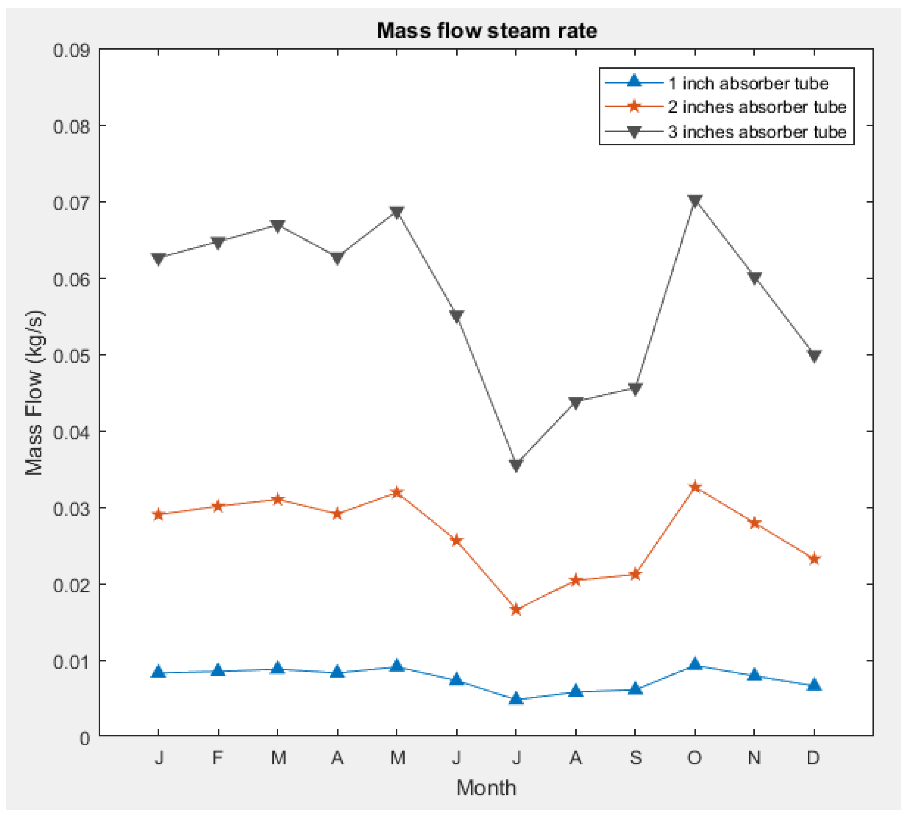
The mass flow steam rate is the main parameter of the PTC collector design, as explained previously, the mass flow directly depends on the solar irradiance reaching the collector, which is the reason why it is imperative to use a good flow control system due to the solar irradiance variation every day and in every season of the year, and even more if the exit temperature must be maintained as constant.
Figure 4 shows the computed mass flow rate for the absorber diameters studied. The mass flow rate increases as the diameter of the absorber tube is augmented. Minimal values of the mass flow steam rate were shown for the 1″ diameter absorber and the highest values were for the 3″ diameter absorber. Additionally, it was observed that in the months with less solar irradiance, the mass flow decreased to maintain the needed energy power for the plant. For the month with the highest solar irradiance, the mass flow steam rate had the maximum value.
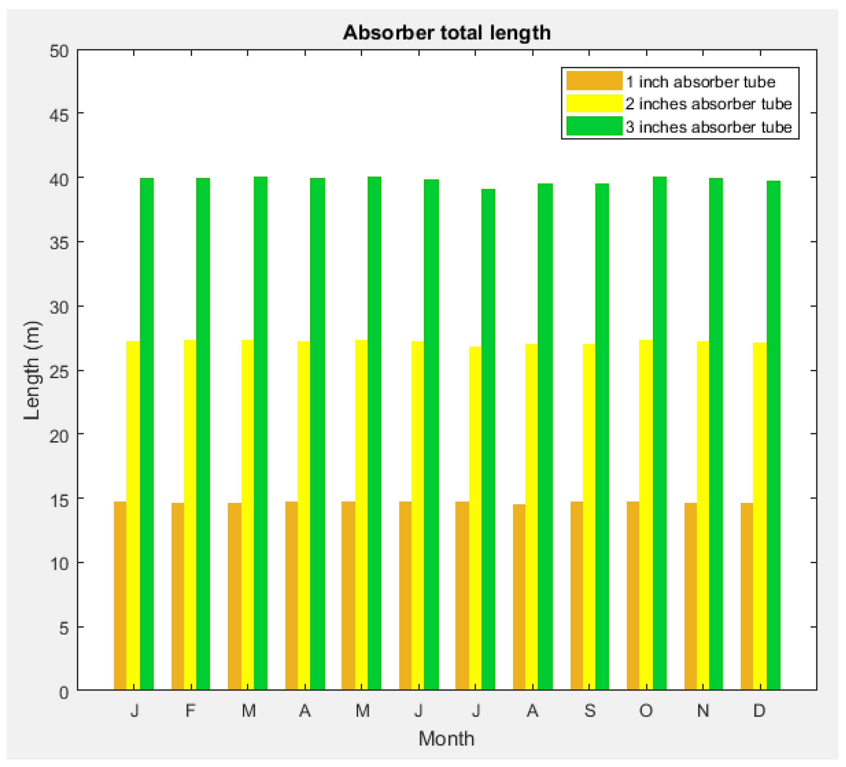
A comparison of the total length for the absorber diameters analyzed is presented in
Figure 5. The total length was almost constant throughout the year for each diameter absorber. The largest length was required for the 3″ absorber diameter while the shortest length for the 1″ absorber diameter. As the diameter in the absorber increased, a higher amount of heat gained was presented. In this sense, a bigger absorber will concentrate more energy and a considerable reduction in the number of concentrators will be required to reach the required power in the steam.
The results show that by using the DSG system in once-through mode, the solar field area necessary to satisfy the saturated steam diminished significantly. The actual PTC collector solar field, installed in the combined cycle power plant Agua Prieta II has a total solar field aperture of 30 hectares, and if the lowest value of solar irradiance is considered as the design point when using the DSG system, the total solar field aperture was 19.379 hectares, which means that the aperture surface decreased by 35.4%. Aside from the decrease in the total installed solar field area, another important advantage of using a DSG system is that the use of heat exchangers is not necessary, reducing the installation costs.
Finally, the objective to prove the feasibility of modifying the Agua Prieta II plant was presented by means of the SOLEEC software application, which evaluated three different geometric combinations that satisfy the necessary power requirements. To make decisions as to whether to improve the plant, more detailed analyses will be required including economic analyses. However, the results shown here can serve as a starting point, thus demonstrating that the SOLEEC software meets the requirements of precision, accuracy, easiness, versatility, and reliability for the analysis of ISCC-PTC-DSG power plants.
6. Conclusions
The present work describes the feasibility of implementing parabolic trough solar collectors with a direct steam generation system in a combined cycle power plant 171 CC Agua Prieta II in the north of Mexico, where the desert climate shows an abundant solar irradiance, making the place an excellent option to leverage solar resources.
The thermal analysis obtained by means of the SOLEEC software provided a comparison between a solar power plant implemented in the combined cycle power plant Agua Prieta II and the proposed PTC solar field using a DSG system in once-through mode. Three kinds of PTC designs were analyzed based on the absorber tube diameter for a saturated steam demand of 20.594 kg/s. All three design proposals satisfied the steam demand, and the results showed that the total aperture area of the solar field was almost constant, having values of 19.379 hectares for the month with the lowest solar irradiance and 9.989 hectares for the month with the highest solar irradiance.
The total aperture area was reduced by 35.4% with the DSG system compared to the actual installed solar field in the CCPT Agua Prieta. Aside from the reduction in the total installed area of the solar field, by using the DSG system, the installation of a heat exchanger is not necessary as the saturated steam is directly produced, reducing the complexity, the installation costs, and the total size.
The use of solar irradiance to produce steam does not generate any kind of exhaust gases that contribute to the greenhouse effect, so in this way, the solar field proposed by the SOLEEC software contributes to diminishing global warming. The numerical tool designed is an excellent tool for evaluating and designing a DSG system with high accuracy.


 ,
, 


