Abstract
A self-supplied circuit that is able to significantly increase the power delivered to a bridge rectifier by a Resonant Piezoelectric Vibration Energy Harvester (RPVEH) is presented and discussed. The proposed circuit, called the Energy Harvester Power Optimizer (EHPO), is implemented by means of a switch-mode converter that emulates a negative capacitance. Unlike switch-mode impedance emulators, based on sophisticated tracking algorithms requiring lossy microcontrollers, EHPO exploits a very light control circuit based on a hysteresis comparator. The EHPO is self-supplied since it does not need an external supply, but it draws the energy for its operation directly from the RPVEH. Moreover, it is developed without the assumption of purely sinusoidal vibrations. Experimental results show that the EHPO can significantly increase the power delivered to a rectifier, both in the case of sinusoidal vibrations (percent gain of the net extracted power up to about 190%) and non-sinusoidal vibrations (percent gain of the net extracted power up to about 245%), regardless of the shape of the forcing acceleration and regardless of the RPVEH resonance frequency.
1. Introduction
Most wireless sensor networks are fed by standard primary batteries or rechargeable batteries [1,2,3]. Batteries have many drawbacks, such as their high cost, limited reliability, need for frequent maintenance (recharge or replacement), and risk to the environment due to hazardous chemical materials. Energy harvesting offers an alternative to battery replacement or, at least, an increase in their lifetime [4,5,6]. The last few years have seen increasing attention devoted to Resonant Piezoelectric Vibration Energy Harvesters (RPVEHs). Recent developments have concerned both the harvester electronic interfaces, aimed at increasing the extracted power [7,8], and the piezoelectric material properties, which contribute to the harvesting performance [9,10]. Significant attention has also been devoted to magnetically activated piezoelectric composites for their promising potential in IoT applications [11,12].
In the presence of sinusoidal vibrations with an angular frequency , the load impedance that maximizes the average power transferred from a harvester to a linear load must be equal to the complex conjugate of the equivalent RPVEH internal impedance [13]. However, in practical applications, the output voltage of an RPVEH needs to be rectified using an AC/DC converter that should be able to emulate [7]. Since (and hence also ) can vary over time, it is also necessary to carry out a tracking process to dynamically emulate the optimal impedance in any possible operating condition. Several single or double-stage active AC/DC converters have been proposed in the literature aimed at the emulation of [8,9,10,11,12,13,14,15,16,17]. However, they cannot be self-supplied due to the complexity of their power stage and their control techniques, usually implemented through lossy microcontrollers. This is the main reason why, in most cases, a passive bridge rectifier is employed for the rectification of the RPVEH output voltage. To the best of the authors’ knowledge, nearly all of the commercial power electronics boards, available on the market for piezoelectric energy-harvesting applications, are equipped with a passive bridge rectifier [18,19,20,21]. Unfortunately, in many cases, passive bridge rectifiers cannot extract the maximum power from RPVEHs, since they are not able to emulate [7]. Therefore, the performance of RPVEHs connected to passive bridge rectifiers can be further improved, even if they are equipped with Maximum Power Point Tracking controllers on their DC side [22]. To achieve that purpose, an inductor could be added, but the necessary value of the inductance is typically too large and cannot adapt to the variations of the input vibrations. As an alternative, interesting non-linear approaches, such as the SSHI [23,24] and the SECE techniques [25,26], have been developed.
In the case of non-sinusoidal vibrations, which are typically encountered in practical applications, it is not possible to define an optimal impedance . Instead, as it will be detailed in the following section, the time-domain compensation of the current drawn by the RPVEH output capacitance can have a boost effect on the power extraction. In this paper, a new approach to compensate the current is presented and discussed for the first time after patent granting [27]. The compensation of is achieved by exploiting a self-supplied switch-mode converter with a light control that, in the following, will be called the “Energy Harvester Power Optimizer” (EHPO). The main characteristic of the EHPO is its capability to behave like a negative capacitance that efficiently operates under arbitrary vibration conditions [28,29]. The EHPO does not require a complex and lossy microcontroller because it does not implement a sophisticated control algorithm. The control circuit is as simple as those employed by SSHI and SECE circuits, and it is specifically designed for non-sinusoidal vibrations. Finally, the EHPO emulates the desired negative capacitance without using a linear amplifier, unlike the circuits that have been very effectively employed for the active damping of structures with piezoelectric transducers [28]. Such circuits provide reactive power to the transducer at the expense of their power supply and, hence, they are not energetically efficient for energy-harvesting applications.
The rest of the paper is organized as follows: In Section 2, the operating principle and the architecture of the EHPO are presented. In Section 3, the actual implementation and the relationships that are useful for design purposes are discussed. Finally, the experimental results are reported in Section 4. Our conclusions end the paper.
2. Operating Principle of the EHPO
The most used equivalent electric circuit of an RPVEH in a cantilever configuration is shown in Figure 1. denotes the vibrating mass, the equivalent stiffness of the piezoelectric cantilever, the viscous damping coefficient, and the force factor describing the piezoelectric effect. Moreover, is the clamp acceleration and is the speed of the cantilever tip. As shown in Figure 1, is the output capacitance of the piezo layers and is the current generated by the piezoelectric effect, which is not only a function of time but also of the piezo output voltage, .
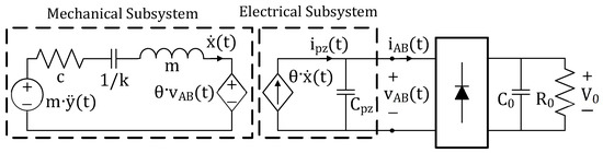
Figure 1.
Equivalent electric circuit of an RPVEH loaded by a diode bridge rectifier.
The capacitance in the electrical subsystem of an RPVEH plays a negative effect on the extraction of power, significantly reducing the maximum power that the rectifier can extract from the harvester. Let us clarify such an aspect by assuming, for the sake of simplicity, negligible voltage drops across the diodes of the bridge rectifier in Figure 1 and .
According to the typical current and voltage waveforms shown in Figure 2, when () and (), it is leading to a power transfer, through the bridge rectifier, to the DC load. When () and , it is , since flows inside . Hence, no instantaneous power can be transferred to the DC load. The capacitance draws the piezoelectric output current during the transitions of between the voltage limits and (from to and vice versa). The bigger , the longer the transitions delay. In order to maximize the power transferred to the load, it is necessary to minimize the time intervals when (and hence ), that is, the rising and falling times of between and .
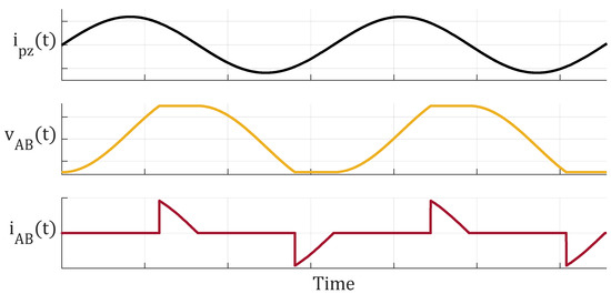
Figure 2.
Typical current and voltage waveforms for a piezoelectric harvester loaded by a bridge rectifier, as shown in Figure 1.
In this paper, a self-supplied circuit to be connected in parallel to the bridge rectifier, EHPO, is proposed, as shown in Figure 3a. The target of the EHPO is to cancel the negative effect of by drawing a current equal to , where is the current drawn by . Thereby, the time intervals when are minimized and the power extraction is maximized. It should be highlighted that the EHPO is able to emulate the negative capacitance regardless of the shape of and without requiring an external supply. The EHPO is intended to draw whatever the working frequency and whatever the shape of the vibration waveform (sinusoidal or not). Such a property makes it incredibly more attractive from a practical point of view, with respect to all those techniques requiring tuning at a specific frequency [7].
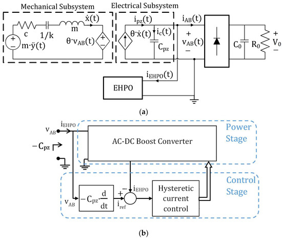
Figure 3.
(a) Connection of EHPO in parallel between an RPVEH and a passive rectifier. (b) Block diagram of EHPO.
The EHPO architecture is based on a switch-mode power converter whose input current is controlled as desired. As shown in the EHPO block diagram of Figure 3b, the input current is controlled by a feedback loop that ensures that follows the desired reference current . Such a reference current, obtained by sensing the input voltage , is the current that would be drawn by the desired negative capacitance . Finally, the current control is implemented through a hysteretic controller, instead of the usual PWM controller, to obtain a faster response in non-sinusoidal reference tracking and to reduce the switching losses. Indeed, the hysteretic controller ensures the lowest switching frequency for a given tracking error.
3. Design and Implementation of the EHPO
In this section, the circuit that implements the EHPO is presented, and its main characteristics are analyzed. Since the EHPO should emulate a negative capacitance, it must allow a bidirectional energy flow. Thus, as shown in Figure 4, it exploits an AC-DC boost converter based on a half-bridge topology, which allows a four-quadrant operation. The implementation of the feedback control loop is described in detail in the following section, and its simplicity, which avoids the adoption of an energy-hungry microcontroller, is shown. Next, the expected duty cycle and the switching frequency are evaluated as a function of the circuit parameters, as needed in the design phase.
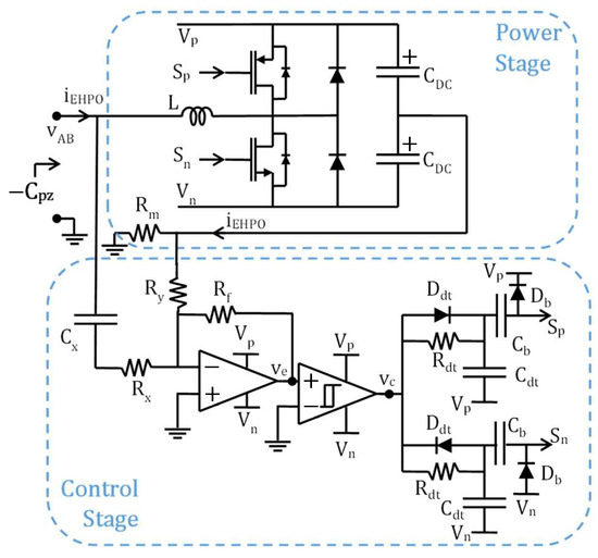
Figure 4.
Schematic of EHPO.
3.1. The Feedback Control Loop
The negative capacitance block and the difference node, shown in the feedback loop of Figure 3b, are implemented by means of an operational amplifier circuit, as shown in Figure 4. Moreover, for the implementation of the hysteretic current control, a hysteresis comparator and two delay networks are used. The expression of the comparator input i.e., the voltage , can be calculated by applying the Kirchhoff’s current law to the op-amp inverting node. Under the assumption of , it results in
which can be rewritten as
where
It should be highlighted that the pole in Equation (3), due to the presence of , is deliberately introduced to limit the op-amp gain at high frequencies and, thus, to prevent possible instability problems. However, if is sufficiently higher than the angular frequency band of the input voltage i.e., , Equation (3) can be simplified as
Equations (2) and (4) confirm that the operational amplifier implements the difference block shown in Figure 3b and that the reference current is proportional to the opposite of the derivative of the input voltage .
The negative feedback loop keeps the comparator input within a hysteresis band around zero. If the hysteresis band is sufficiently small, it is and, according to Equations (2) and (4), it results in
Equation (5) proves that, under current control, the EHPO draws a current that is proportional to the opposite of the time derivative of , that is, the EHPO emulates a negative capacitance. The emulated negative capacitance is just equal to provided that . Therefore, the values of the resistances and and of the capacitance should be chosen according to the value of the internal capacitance of the specific piezoelectric harvester to be compensated. However, such values are independent of the shape of the input vibrations and the possible mechanical tuning of the cantilever structure of the RPVEH, which regulates its resonance frequency [5].
Note that, a dead time is introduced in the control signals ( and ) of the upper and lower MOS switches of the converter leg, by means of the two delay networks made up by , , and at the output of the hysteresis comparator. This is enacted to prevent the simultaneous conduction of the two MOS in correspondence with the commutation times. In this way, the turn-on of a MOS is delayed by the network and the turn-off of the other MOS is sped up by the action of diode . Moreover, the presence of the two networks composed by and ensures that none of the two MOS switches remain blocked in the ON state at the system start-up, when the capacitors are not still charged. In particular, the capacitor is large enough to behave like a short circuit in normal operations, whereas, to avoid the MOS remaining blocked in the ON state, it disconnects its gate from the relative control signal after a sufficiently long stationary time. In this way, the reverse current of the diode turns off the MOS.
It is worth noting that, with reference to the hysteretic controller, the amplitude of the hysteresis band of the comparator determines the acceptable error on the voltage tracking. Such an error, as will be investigated in the next section, is also affected by the delay introduced by the comparator. Due to the low power constraints of the considered application, the chosen comparator should have a very low power consumption, which unavoidably leads to a delay that needs to be properly considered.
Further, note that the EHPO is self-supplied since it does not need an external supply, but it draws the energy for its operation directly from the RPVEH. As shown in Figure 4, the op-amp and the comparator are supplied by the capacitors . They are charged at the voltage levels and , with the energy drawn directly from the RPVEH, by the diodes that are in parallel to the MOS switches. The voltage levels and are nearly equal to the peak values of the input voltage , so that the difference is nearly equal to the peak-to-peak amplitude of . In the experimental tests that are shown in Section 4, the average power that is drawn by the EHPO during its operation is reported for different operating conditions.
Finally, let us underline that the feedback loop implemented by the EHPO is stable as the initial start-up transient, reported in Figure 5, shows. In Figure 5, simulated waveforms are reported for an EHPO connected between a piezoelectric harvester driven by a sinusoidal acceleration and a bridge rectifier.
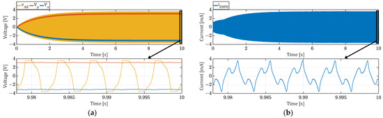
Figure 5.
Simulated waveforms of EHPO (implemented with the parameters in Table 1) during the start-up transient. (a) Voltage waveforms; (b) Current waveform.
3.2. The Duty Cycle and the Switching Frequency
Differently from a PWM control, in a hysteretic control, both the duty cycle and the switching frequency change, during the circuit operation, as a function of the input voltage . For a proper design of the circuit, the dependence of the duty cycle and the switching frequency on and the circuit parameters is discussed in this section.
By imposing the quasi-stationary condition on the inductor current in Figure 4, it is possible to obtain the expression of the duty cycle . When , the quasi-stationary condition leads to , that is
and, hence
On the other hand, when , the quasi-stationary condition leads to , that is
and, hence
Expressions (7) and (9) state that, under the quasi-stationary condition, the expression of the duty cycle is the same for and . Therefore, under the reasonable assumption of zero mean input voltage i.e., , it is
To calculate the expression of the switching frequency , let us consider the time evolutions of the reference current signal and of the EHPO input current , shown in Figure 6. Since the comparator input is kept within a hysteresis band around zero, according to Equation (2), the input current is kept within a hysteresis bandwidth equal to around the reference current . According to the schematic in Figure 4, when and the NMOS control signal is on, the time needed by the current to cross, during its rise, the entire current hysteresis bandwidth is given by

Figure 6.
Typical waveforms of the MOS control signals and and of the currents and .
Instead, when the NMOS is off, such a time is
Moreover, it should be considered that the turn-on of the NMOS device is delayed, with respect to the end of the previous time interval , by a time due to the comparator delay. During , the falling current goes out of the current hysteresis bandwidth of a quantity equal to
This implies that, after the turn-on of the NMOS, requires a supplementary time to come back inside the hysteresis bandwidth. is given by
In a similar way, the turn-off of the NMOS device is delayed with respect to by a time . During , the rising current goes out of the hysteresis bandwidth of a quantity equal to
and the supplementary time required to come back inside the hysteresis bandwidth is equal to
Taking into account that similar considerations also hold for , the total switching time can be expressed as the sum of the above partial times given by Equations (11), (12), (14) and (16) as
Thus, under the reasonable assumption of zero mean input voltage i.e., , the switching frequency is given by
Equations (10) and (18) allow us to predict the time evolution of the duty cycle and the switching frequency as a function of the input electrical quantities.
In Figure 7, Equations (10) and (18) are compared with the corresponding waveforms obtained by means of numerical simulations of the circuit in Figure 4 in case of a purely sinusoidal voltage . It is interesting to observe that the switching frequency varies between zero and its maximum value, with a frequency double that of . The maximum switching frequency is reached when the input voltage crosses zero. Moreover, it is interesting to note that when the current crosses zero, the duty cycle assumes a value equal to or . This means that, when the current crosses zero, the switching does not take place. This behavior is confirmed by the experimental results reported in the following section.
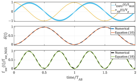
Figure 7.
Waveforms as a function of the normalized time. is the maximum of the current and is the period of .
From Equation (18), it is possible to predict that the maximum switching frequency is
Equation (19) provides a useful relationship between the circuit parameters and the maximum switching frequency. It is worth noting that the maximum switching frequency must be kept sufficiently low to reduce the switching losses. Therefore, the EHPO parameters should be accurately chosen to guarantee a suitable compromise between the increase in the extracted power, due to the negative capacitance emulation, and the associated switching losses.
4. Experimental Results
A prototype of the EHPO, shown in Figure 8a, was implemented with the parameters in Table 1, which ensure a compromise between negative capacitance emulation and switching loss minimization. Experimental tests were performed to show the significant increase in power extraction obtained by inserting the EHPO in parallel with a RPVEH loaded by a bridge rectifier. The tests were carried out using the architecture shown in Figure 8b and by applying both sinusoidal and non-sinusoidal vibrations to the harvester. It is worth noting that the operation of the EHPO is independent of the type of diode rectifier that is connected to the RPVEH terminals. In the considered architecture, without any loss of generality, a diode half-bridge rectifier was used, which could be useful for increasing the output DC voltage. The half-bridge rectifier shown in Figure 8b is made up of two diodes, 1N5817 by ST Microelectronics, and two 100 µF 50 V aluminum electrolytic capacitors by Lelon; the value of the resistance at the output of the bridge rectifier was varied to identify the maximum power extraction condition.
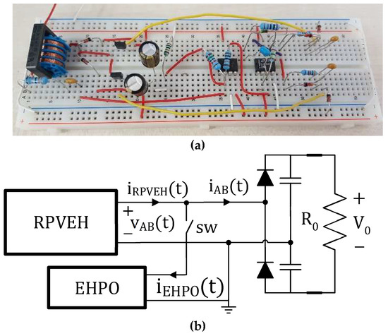
Figure 8.
(a) Photo of the prototype of EHPO. (b) Architecture of the system under test.

Table 1.
Parameters of EHPO under test.
The experimental tests were performed using the RPVEH PPA4011 by MIDE mounted on the two different mechanical configurations shown in Figure 9. The circuit parameters of the EHPO were not modified during the tests, independently of the shape of the input vibrations and the RPVEH resonance frequency resulting from its mechanical configuration. To achieve the desired acceleration, the shaker 50009 by TIRAvib equipped with the power amplifier BAA 60 was used. The accelerometers used to monitor the acceleration on the constrained terminal of the cantilever beam were the 355B04 by PCB Piezotronics (sensitivity 1 V/g and measurement range ±5 g peak) and the 352C33 by PCB Piezotronics (sensitivity 100 mV/g and measurement range ±50 g peak).

Figure 9.
Harvester PPA4011 by MIDE mounted on the two tested configurations. (a) Configuration C1 (tuned at 232 Hz). (b) Configuration C2 (tuned at 477 Hz).
4.1. Sinusoidal Input Vibrations
The first tests were carried out using the RPVEH mounted on the configuration C1 shown in Figure 9a. The harvester was forced by a sinusoidal vibration with a frequency equal to the RPVEH open circuit resonance frequency, 232 Hz, and an acceleration amplitude equal to 2 g. The results of the tests are reported in Figure 10, and examples of the measured waveforms are reported in the oscilloscope screenshots in Figure 11. The meanings of the symbols are as follows: is the resistance at the output of the bridge rectifier. is the average of the power extracted from the RPVEH when the EHPO is connected at the harvester terminals (the switch sw of Figure 8b is closed). is the average of the power that is drawn by the EHPO when it is working. is the average of the power provided to the diode bridge rectifier (DBR) when the EHPO is connected at the harvester terminals (the switch sw of Figure 8b is closed). is the average of the power provided to the bridge rectifier when the EHPO is not connected (the switch sw of Figure 8b is open). In Figure 10a, the performance of the EHPO circuit is analyzed in detail by showing the total extracted power , the dissipated power , and the net extracted power . It is worth noting that, the power , which is needed for the operation of the EHPO, is directly drawn from the RPVEH terminals without any other external supply, making it a self-supplied device. In Figure 10b, the EHPO is compared with a standard DBR () by considering both the total power that can be extracted from the RPVEH () and the net extracted power (). In Figure 10c, the percentage gains of power are shown. In particular, is the percentage gain of total power at the RPVEH terminals, and it is given by
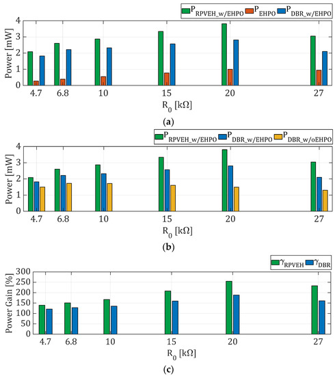
Figure 10.
Results of the tests of configuration C1 with a sinusoidal vibration. (a) Performance of the EHPO circuit; (b) Comparison of the EHPO with a standard DBR; (c) Percentage gains of power. is the resistance at the output of the bridge rectifier. is the average of the power extracted from the RPVEH when the EHPO is connected at the harvester terminals (the switch sw of Figure 8b is closed). is the average of the power that is drawn by the EHPO when it is working. is the average of the power provided to the DBR when the EHPO is connected at the harvester terminals (the switch sw of Figure 8b is closed). is the average of the power provided to the bridge rectifier when the EHPO is not connected (the switch sw of Figure 8b is open). is the percentage gain of total power at the RPVEH terminals, and it is given by Equation (20). is the percentage gain of net power at the RPVEH terminals, and it is given by Equation (21).
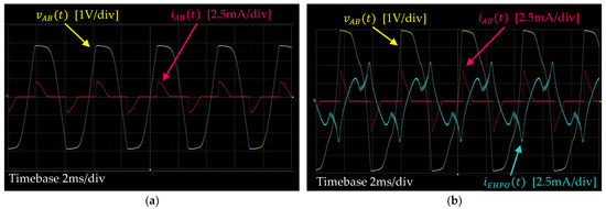
Figure 11.
Waveforms measured when the harvester is tuned at 232 Hz, the acceleration is sinusoidal, and . (a) EHPO is not connected. (b) EHPO is connected.
is the percentage gain of net power at the RPVEH terminals, and it is given by
The results in Figure 10 show that, in the presence of the EHPO, a significant increase in the extracted power can be obtained, with a percentage total power gain () that can reach 250% and a percentage net power gain () that can reach about 190%.
The difference between and is due to the losses taking place in the actual implementation with discrete components of the EHPO circuit. Such losses, which are shown in detail in Figure 10a, can be reduced if an integrated implementation of the circuit is considered, leading to an increase in the net power gain () that will approach the total power gain (). It is also interesting to observe that, without the EHPO, the maximum average power that the standard diode bridge rectifier can extract is obtained in correspondence of and it is equal to , as shown in Figure 10b. On the other hand, in the presence of the EHPO, the maximum average net power is extracted in correspondence of and it is equal to . This means that, by employing a DC/DC converter equipped with a Maximum Power Point Tracking (MPPT) controller [7], connected at the output of the passive bridge rectifier (both with and without EHPO), the MPPT power gain is .
Note that the EHPO is self-supplied through the RPVEH terminals. Thus, only if is greater than a given threshold (related to the minimum supply voltage of the electronic components) can the EHPO work properly. In the present implementation, the minimum value needed for the peak-to-peak amplitude of is about .
A last interesting consideration concerns the impact of the EHPO on the operation and efficiency of the diode bridge rectifier connected at the RPVEH terminals. The comparison of the gains of power obtained at the AC side and the DC side of the rectifier as a function of the load resistance is shown in Figure 12. is the percentage gain of net power at the DC side of the rectifier, and it is given by
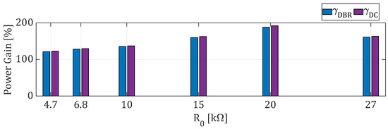
Figure 12.
Results of the tests of configuration C1 with a sinusoidal vibration. is the resistance at the output of the bridge rectifier. is the percentage gain of net power at the rectifier AC side, and it is given by Equation (21). is the percentage gain of net power at the rectifier DC side, and it is given by Equation (22).
is the average of the power provided to the load resistance when the EHPO is connected at the harvester terminals (the switch sw of Figure 8b is closed). is the same average power provided to when the EHPO is not connected (the switch sw of Figure 8b is open). and , respectively, are the voltage potentials, with respect to the ground, of the upper and lower terminals of , and is the current flowing into such a resistance. In Figure 13, an example of waveforms at the AC and DC sides of the rectifier is reported with reference to the case . The results in Figure 12 show that the efficiency of the rectifier is essentially not affected by the connection of the EHPO, and the significant increase in the extracted power obtained in the presence of the EHPO is also confirmed at the rectifier DC side.
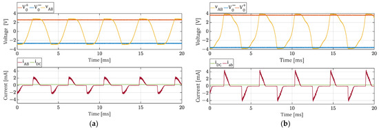
Figure 13.
Example of waveforms at the AC side ( and ) and at the DC side (, , and , being ) of the bridge rectifier (the harvester is tuned at 232 Hz, the acceleration is sinusoidal, and ). (a) EHPO is not connected. (b) EHPO is connected.
4.2. Non-Sinusoidal Input Vibrations
The second set of tests of the EHPO was carried out under non-sinusoidal vibrations. Firstly, the RPVEH mounted on the configuration C1 shown in Figure 9a was used. The voltage signal that was applied to the shaker amplifier is a scaled form of the acceleration of the vibration measured on an aircraft (the fuselage side of a flying Boeing 737 [30]) and is reported in Figure 14. It is characterized by a dominant frequency around 232 Hz and produces an acceleration on the constrained terminal of the RPVEH cantilever beam with an RMS value equal to about 5 g. The results of such tests are reported in Figure 15, and examples of measured waveforms are reported in the oscilloscope screenshots in Figure 16. Figure 15 shows very good performance of the EHPO also under non-sinusoidal vibrations, with a percent total power gain () that reaches about 270% and a percent net power gain () that reaches about 180%. Moreover, by comparing the maximum net power extracted from the RPVEH when the EHPO is not connected () and the maximum net power extracted when the EHPO is connected (), it can be observed that the MPPT power gain is about .

Figure 14.
(a) Voltage signal applied to the shaker amplifier (scaled form of the acceleration of the vibration measured on the fuselage side of a flying Boeing 737 [30]). (b) Corresponding FFT (amplitudes).
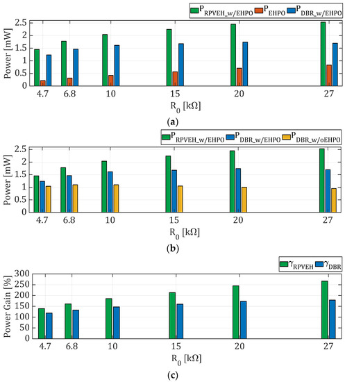
Figure 15.
Results of the tests of configuration C1 with a non-sinusoidal vibration (signal of Figure 14). (a) Performance of the EHPO circuit; (b) Comparison of the EHPO with a standard DBR; (c) Percentage gains of power. is the average of the power extracted from the RPVEH when the EHPO is connected at the harvester terminals (the switch sw of Figure 8b is closed). is the average of the power that is drawn by the EHPO when it is working. is the average of the power provided to the DBR when the EHPO is connected at the harvester terminals (the switch sw of Figure 8b is closed). is the average of the power provided to the bridge rectifier when the EHPO is not connected (the switch sw of Figure 8b is open). is the percentage gain of total power at the RPVEH terminals, and it is given by Equation (20). is the percentage gain of net power at the RPVEH terminals, and it is given by Equation (21).
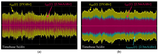
Figure 16.
Waveforms measured when the harvester is tuned at 232 Hz, the acceleration is non-sinusoidal, and . (a) EHPO is not connected. (b) EHPO is connected.
To show the ability of the EHPO to work whatever the RPVEH mechanical configuration, the harvester PPA 4011 was mounted on a different configuration i.e., C2 in Figure 9b. In such a configuration, it exhibits an open circuit resonance frequency equal to 477 Hz. Tests of such a new mechanical configuration were carried out by applying a signal to the shaker amplifier that is a scaled form of the acceleration of the vibration measured on a car (Ford Focus diesel engine turned on [31]) and reported in Figure 17. Such a vibration is characterized by a dominant frequency around 477 Hz and an RMS value of the acceleration measured on the constrained terminal of the RPVEH cantilever equal to about 5 g. It is worth noting that the same EHPO circuit, used in the previous tests with configuration C1, was also able to work with the configuration C2 without any modification.
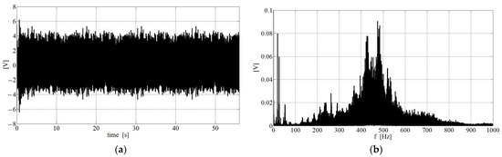
Figure 17.
(a) Voltage signal applied to the shaker amplifier (scaled form of the acceleration of the vibration measured on a Ford Focus diesel engine turned on [31]). (b) Corresponding FFT (amplitudes).
The results of such experimental tests are reported in Figure 18, and examples of the measured waveforms are reported in the oscilloscope screenshots in Figure 19. The results of Figure 18 show that, also in these different mechanical conditions, the performances of the EHPO under non-sinusoidal vibrations are very good. The percentage total power gain () reaches about 398%, and the percentage net power gain () reaches about 245%. Moreover, since the maximum power extracted by the harvester without the EHPO is and the maximum net power extracted when the EHPO is connected is , in this case it is about .

Figure 18.
Results of the tests of configuration C2 with a non-sinusoidal vibration (signal of Figure 17). (a) Performance of the EHPO circuit; (b) Comparison of the EHPO with a standard DBR; (c) Percentage gains of power. is the average of the power extracted from the RPVEH when the EHPO is connected at the harvester terminals (the switch sw of Figure 8b is closed). is the average of the power that is drawn by the EHPO when it is working. is the average of the power provided to the DBR when the EHPO is connected at the harvester terminals (the switch sw of Figure 8b is closed). is the average of the power provided to the bridge rectifier when the EHPO is not connected (the switch sw of Figure 8b is open). is the percentage gain of total power at the RPVEH terminals, and it is given by Equation (20). is the percentage gain of net power at the RPVEH terminals, and it is given by Equation (21).
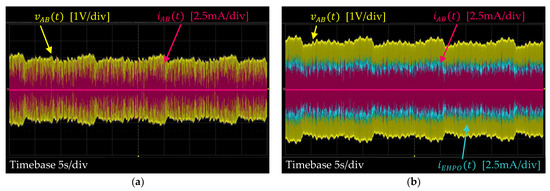
Figure 19.
Waveforms measured when the harvester is tuned at 477 Hz, the acceleration is non-sinusoidal, and . (a) EHPO is not connected. (b) EHPO is connected.
The experimental results, which have been shown in this section, confirm the ability of the EHPO to significantly increase the power extracted from an RPVEH. It is possible to highlight that the EHPO can operate both in the case of sinusoidal and non-sinusoidal vibrations, regardless of the shape of the input acceleration and the RPVEH resonance frequency. Moreover, the EHPO does not need an external power supply, but it draws the power for its operation directly from the RPVEH terminals. Such a power, , was measured in all the different testing conditions and reported in Figure 10a, Figure 15a and Figure 18a. , which is the reason for the difference between and , can be strongly reduced with an integrated implementation of the EHPO.
A comparison of the proposed EHPO circuit with the most recent RPVEH optimizer circuits is reported in Table 2. In the last few years, many self-supplied circuits have been proposed implementing SSHI, SECE, and Impedance Matching techniques. They are mainly devoted to increasing the extracted power from RPVEHs by compensating the output piezo capacitance. The proposed EHPO circuit is designed for the same goal, but it exploits a very light control technique aimed at emulating a negative capacitance. Moreover, research efforts on non-sinusoidal vibrations have mainly focused on circuit optimization for impact vibrations. Differently, the EHPO, by emulating a negative capacitance, can compensate the RPVEH output capacitance in every working condition, regardless of the shape of the non-sinusoidal forcing acceleration. Furthermore, among the circuits implemented with discrete components, the EHPO is the only one that is tested both in sinusoidal and non-sinusoidal conditions, and, despite its simplicity, it leads to very high gains of power in both conditions. Finally, considering that the integrated circuit implementation allows an increase in overall efficiency, further improvements in power gain will be possible thanks to an integrated implementation of the EHPO.
Table 2.
Comparison of the proposed EHPO with the state of the art.
5. Conclusions
In this paper, a new self-supplied circuit, named the EHPO, aimed at the optimization of the extraction of power from RPVEHs, was presented and discussed. It compensates the electrical current drawn by the RPVEH output capacitance by exploiting a switch-mode converter and a very light control circuit based on a hysteresis comparator. By emulating a negative capacitance, the EHPO can lead to a significant increase in the power provided by an RPVEH to a passive rectifier. A prototype of the proposed circuit was implemented using discrete components on a breadboard and tested. The experimental results show that the EHPO significantly increases the power extracted from a commercial RPVEH, both in the case of sinusoidal and non-sinusoidal vibrations, regardless of the shape of the forcing acceleration and the RPVEH resonance frequency. The EHPO’s performance is very promising and can be further improved by integrating it on a chip.
6. Patents
In this paper, a new technology is presented and discussed for the first time after patent granting.
European Patent EP3942686. Title: Electronic device and method for the maximization of the average power extracted from a vibration harvester. Inventors: L. Costanzo, A. Lo Schiavo, M. Vitelli. Applicant: Università degli Studi della Campania Luigi Vanvitelli. Italian Patent Granting Date: 4 February 2021, European Patent Publication Date: 26 January 2022; Links:
https://register.epo.org/application?number=EP20719490 (accessed on 23 May 2023).
https://patentscope.wipo.int/search/en/detail.jsf?docId=EP348440005 (accessed on 23 May 2023).
https://patents.google.com/patent/EP3942686A1/en (accessed on 23 May 2023).
Author Contributions
Conceptualization, L.C., A.L.S. and M.V.; Data curation, L.C., A.L.S., and M.V.; Formal analysis, L.C., A.L.S. and M.V.; Funding acquisition, L.C., A.L.S. and M.V.; Investigation, L.C., A.L.S. and M.V.; Methodology, L.C., A.L.S. and M.V.; Project administration, L.C., A.L.S. and M.V.; Resources, L.C., A.L.S. and M.V.; Software, L.C., A.L.S. and M.V.; Validation, L.C., A.L.S. and M.V.; Visualization, L.C., A.L.S. and M.V.; Writing–original draft, L.C., A.L.S. and M.V.; Writing—review and editing, L.C., A.L.S. and M.V. All authors have read and agreed to the published version of the manuscript.
Funding
This work was supported in part by Università degli Studi della Campania Luigi Vanvitelli in the framework of “Piano Strategico di Ateneo 2021–2023-Azione strategica R1.S2” under Grant SCAVENGE.
Data Availability Statement
No available data.
Acknowledgments
The vibration data of Section 4.2 is provided on an “as is” basis through EnABLES, funded by the EU H2020 Infrastructure Programme (H2020-INFRAIA-02-2017) under the Grant Agreement 730957.
Conflicts of Interest
The authors declare no conflict of interest.
References
- Hung, L.-L.; Leu, F.-Y.; Tsai, K.-L.; Ko, C.-Y. Energy-Efficient Cooperative Routing Scheme for Heterogeneous Wireless Sensor Networks. IEEE Access 2020, 8, 56321–56332. [Google Scholar] [CrossRef]
- Femine, A.D.; Gallo, D.; Landi, C.; Schiavo, A.L.; Luiso, M. Low Power Contactless Voltage Sensor for Low Voltage Power Systems. Sensors 2019, 19, 3513. [Google Scholar] [CrossRef] [PubMed]
- Gulati, K.; Boddu, R.S.K.; Kapila, D.; Bangare, S.L.; Chandnani, N.; Saravanan, G. A review paper on wireless sensor network techniques in Internet of Things (IoT). Mater. Today Proc. 2021, 51, 161–165. [Google Scholar] [CrossRef]
- Harb, A. Energy harvesting: State-of-the-art. Renew. Energy 2011, 36, 2641–2654. [Google Scholar] [CrossRef]
- Costanzo, L.; Vitelli, M. Tuning Techniques for Piezoelectric and Electromagnetic Vibration Energy Harvesters. Energies 2020, 13, 527. [Google Scholar] [CrossRef]
- Costanzo, L.; Liu, M.; Schiavo, A.L.; Vitelli, M.; Zuo, L. Backpack Energy Harvesting System with Maximum Power Point Tracking Capability. IEEE Trans. Ind. Electron. 2022, 69, 506–516. [Google Scholar] [CrossRef]
- Brenes, A.; Morel, A.; Juillard, J.; Lefeuvre, E.; Badel, A. Maximum power point of piezoelectric energy harvesters: A review of optimality condition for electrical tuning. Smart Mater. Struct. 2020, 29, 033001. [Google Scholar] [CrossRef]
- Costanzo, L.; Schiavo, A.L.; Vitelli, M. Active Interface for Piezoelectric Harvesters Based on Multi-Variable Maximum Power Point Tracking. IEEE Trans. Circuits Syst. I Regul. Pap. 2020, 67, 2503–2515. [Google Scholar] [CrossRef]
- Piliposian, G.; Hasanyan, A.; Jilavyan, H. On the Sensing, Actuating and Energy Harvesting Properties of a Composite Plate with Piezoelectric Patches. Int. J. Precis. Eng. Manuf. Technol. 2020, 7, 657–668. [Google Scholar] [CrossRef]
- Li, T.; Lee, P.S. Piezoelectric Energy Harvesting Technology: From Materials, Structures, to Applications. Small Struct. 2022, 3, 2100128. [Google Scholar] [CrossRef]
- Brito-Pereira, R.; Ribeiro, C.; Pereira, N.; Lanceros-Mendez, S.; Martins, P. Printed multifunctional magnetically activated energy harvester with sensing capabilities. Nano Energy 2022, 94, 106885. [Google Scholar] [CrossRef]
- Shi, Y.; Li, N.; Ye, J.; Ma, J. Enhanced magnetoelectric response in nanostructures due to flexoelectric and flexomagnetic effects. J. Magn. Magn. Mater. 2020, 521, 167523. [Google Scholar] [CrossRef]
- Kong, C.S. A general maximum power transfer theorem. IEEE Trans. Educ. 1995, 38, 296–298. [Google Scholar] [CrossRef]
- Liao, Y.; Liang, J. Maximum power, optimal load, and impedance analysis of piezoelectric vibration energy harvesters. Smart Mater. Struct. 2018, 27, 075053. [Google Scholar] [CrossRef]
- Minami, M. Improvement in Output Characteristics Using a Resonator and Passive Rectifiers in Vibration Generators. IEEE Trans. Power Electron. 2018, 34, 7184–7191. [Google Scholar] [CrossRef]
- Ulusan, H.; Gharehbaghi, K.; Zorlu, O.; Muhtaroglu, A.; Kulah, H. A Fully Integrated and Battery-Free Interface for Low-Voltage Electromagnetic Energy Harvesters. IEEE Trans. Power Electron. 2014, 30, 3712–3719. [Google Scholar] [CrossRef]
- Hsieh, C.-Y.; Huang, B.; Golnaraghi, F.; Moallem, M. Regenerative Skyhook Control for an Electromechanical Suspension System Using a Switch-Mode Rectifier. IEEE Trans. Veh. Technol. 2016, 65, 9642–9650. [Google Scholar] [CrossRef]
- Datasheet. Available online: https://www.analog.com/en/products/ltc3588-1.html (accessed on 23 May 2023).
- Datasheet. Available online: https://www.analog.com/en/products/ltc3331.html (accessed on 23 May 2023).
- Datasheet. Available online: http://www.ti.com/tool/TIDA-00690#0 (accessed on 23 May 2023).
- Datasheet. Available online: https://datasheets.maximintegrated.com/en/ds/MAX17710.pdf (accessed on 23 May 2023).
- Costanzo, L.; Schiavo, A.L.; Vitelli, M. Design Guidelines for the Perturb and Observe Technique for Electromagnetic Vibration Energy Harvesters Feeding Bridge Rectifiers. IEEE Trans. Ind. Appl. 2019, 55, 5089–5098. [Google Scholar] [CrossRef]
- Guyomar, D.; Badel, A.; Lefeuvre, E.; Richard, C. Toward energy harvesting using active materials and conversion improvement by nonlinear processing. IEEE Trans. Ultrason. Ferroelectr. Freq. Control 2005, 52, 584–595. [Google Scholar] [CrossRef]
- Wu, L.; Do, X.-D.; Lee, S.-G.; Ha, D.S. A Self-Powered and Optimal SSHI Circuit Integrated with an Active Rectifier for Piezoelectric Energy Harvesting. IEEE Trans. Circuits Syst. I Regul. Pap. 2017, 64, 537–549. [Google Scholar] [CrossRef]
- Dicken, J.; Mitcheson, P.D.; Stoianov, I.; Yeatman, E.M. Power-extraction circuits for piezoelectric energy harvesters in miniature and low-power applications. IEEE Trans. Power Electron. 2012, 27, 4514–4529. [Google Scholar] [CrossRef]
- Lefeuvre, E.; Badel, A.; Brenes, A.; Seok, S.; Woytasik, M.; Yoo, C.S. Analysis of piezoelectric energy harvesting system with tunable SECE interface. Smart Mater. Struct. 2017, 26, 035065. [Google Scholar] [CrossRef]
- Patent. Available online: https://patentscope.wipo.int/search/en/detail.jsf?docId=EP348440005&_cid=P10-L2A8TC-36138-1 (accessed on 23 May 2023).
- De Marneffe, B.; Preumont, A. Vibration damping with negative capacitance shunts: Theory and experiment. Smart Mater. Struct. 2008, 17, 035015. [Google Scholar] [CrossRef]
- Neri, I.; Travasso, F.; Mincigrucci, R.; Vocca, H.; Orfei, F.; Gammaitoni, L. A real vibration database for kinetic energy harvesting application. J. Intell. Mater. Syst. Struct. 2012, 23, 2095–2101. [Google Scholar] [CrossRef]
- Vibration Signal. Available online: http://realvibrations.nipslab.org/node/235 (accessed on 23 May 2023).
- Vibration Signal. Available online: http://realvibrations.nipslab.org/node/152 (accessed on 23 May 2023).
- Yao, M.; Li, J.; Niu, Y. Adaptive impedance matching for power management circuit for a piezoelectric energy harvester on the bridge. Sens. Actuators A Phys. 2021, 331, 112986. [Google Scholar] [CrossRef]
- Yang, L.; Wei, T.; Chen, N. High-Efficiency Energy Management Circuit Combining Synchronized Switch Harvesting on Inductor Rectifier and Impedance Matching for Impact-Type Piezoelectric Energy Harvester. Energy Technol. 2022, 10, 2200434. [Google Scholar] [CrossRef]
- Fang, S.; Xia, H.; Xia, Y.; Ye, Y.; Shi, G.; Wang, X.; Chen, Z. An Efficient Piezoelectric Energy Harvesting Circuit with Series-SSHI Rectifier and FNOV-MPPT Control Technique. IEEE Trans. Ind. Electron. 2021, 68, 7146–7155. [Google Scholar] [CrossRef]
- Yang, L.; Wei, T.; Chen, N. A Piezoelectric Energy Management Circuit Combining ReL-SSHI and MPPT for Impact-Type Piezoelectric Harvesters. In Proceedings of the 2022 7th International Conference on Integrated Circuits and Microsystems (ICICM), Xi’an, China, 28–31 October 2022; pp. 12–16. [Google Scholar] [CrossRef]
- Ammar, M.B.; Sahnoun, S.; Fakhfakh, A.; Viehweger, C.; Kanoun, O. Self-Powered Synchronized Switching Interface Circuit for Piezoelectric Footstep Energy Harvesting. Sensors 2023, 23, 1830. [Google Scholar] [CrossRef]
- Chamanian, S.; Ciftci, B.; Muhtaroglu, A.; Kulah, H. A Self-Powered and Area Efficient SSHI Rectifier for Piezoelectric Harvesters. IEEE Access 2021, 9, 117703–117713. [Google Scholar] [CrossRef]
- Lo, Y.; Shu, Y. Self-powered SECE piezoelectric energy harvesting induced by shock excitations for sensor supply. Mech. Syst. Signal Process. 2022, 177, 109123. [Google Scholar] [CrossRef]
Disclaimer/Publisher’s Note: The statements, opinions and data contained in all publications are solely those of the individual author(s) and contributor(s) and not of MDPI and/or the editor(s). MDPI and/or the editor(s) disclaim responsibility for any injury to people or property resulting from any ideas, methods, instructions or products referred to in the content. |
© 2023 by the authors. Licensee MDPI, Basel, Switzerland. This article is an open access article distributed under the terms and conditions of the Creative Commons Attribution (CC BY) license (https://creativecommons.org/licenses/by/4.0/).