Abstract
Given the fact that the operation of electrical machines generates various loss components that finally become heat, developing advanced thermal management technologies is essential to control temperature increases and to guarantee safe operations. Meanwhile, the armature winding can stand larger currents when the machines are equipped with advanced cooling systems, which directly improves torque/power densities. This paper aims to provide a systematic review of the latest developments of advanced thermal management technologies of electrical machines. According to different heat dissipation mechanisms, the cooling systems studied in this paper are categorized into five major types: enclosed housing cooling, enhanced conductive cooling, embedded heat pipe cooling, direct oil cooling, and enhanced rotor cooling. The advantages and disadvantages of these cooling systems are researched and compared comprehensively. This study contributes to the revelation of insights on the thermal management of electrical machines and offers good guidance for the thermal management of electrical machines.
1. Introduction
With increasing concerns on energy shortage and environmental pollution, electrical machines are attracting significant attention because of their zero-emission feature. The principle applications of electrical machines include electric vehicle (EV) propulsion [1], renewable energy generation [2,3,4], industrial drive [5], and home appliances [6], etc. The development of electrical machines has a history of more than one hundred years, and various electrical machines have been investigated to meet the requirements of different applications, such as DC machines, induction machines, permanent magnet (PM) machines, and switched reluctance machines, etc. The power rating of the electrical machines used in our modern society ranges from watts to megawatts. Renewable energy systems and industrial automation are the two major stimulators of the fast development of electrical machines. Despite the fact that the success of industrial automation relies on advanced data exchange, machine learning, and artificial intelligence, electric motors are always the actuators that turn many intelligent thoughts into reality, such as driving automated production lines, robots, and autonomous vehicles.
The design of electrical machines has a multi-physical nature, which involves electromagnetic design, mechanical analysis, and thermal management. The operation of electrical machines generates various loss components, such as copper loss, iron loss, magnet loss, and mechanical loss, all of which turn to be heat and cause temperature increases. Therefore, thermal management is essential to guarantee the safe operation of electrical machines. Meanwhile, since the toque of electrical machine is proportional to armature currents, advanced thermal management techniques that allow for larger armature current contribute to the improvement of the torque/power density of electrical machines. The typical components of electrical machines, such as the air-gap, stator and rotor laminations, windings, winding insulations, and magnets, have different thermal properties, which renders thermal analysis complicated. Meanwhile, a significant portion of effort has been made on developing advanced machine concepts over the past decades [7,8,9,10,11,12,13], such as dual stator/rotor machines, magnetic geared machines, flux switching machines, doubly salient machines, and vernier machines. The performance of electrical machines has been significantly improved; on the other hand, the machine structure is also becoming more complicated, which provides more challenges on thermal management.
The thermal analysis of electrical machines has been widely conducted by researchers, which mainly includes the lumped parameter thermal method (LPTN) [14,15,16], numerical methods [17], and experimental calibration [18]. The heat inside the machine can be extracted by utilizing conduction, convection (natural and forced), and radiation. Based on the machine topologies and practical application requirements, various thermal management technologies have been developed. This paper aims to provide a comprehensive review of the state-of-the-art of thermal management technologies of electrical machines. The paper will be organized as follows: Section 2, Section 3, Section 4, Section 5 and Section 6 will review enclosed housing cooling, enhanced conductive cooling, embedded heat pipe cooling, direct oil cooling, and enhanced rotor cooling, respectively. Finally, Section 7 will summarize and compare the characteristics of the cooling systems reviewed in this paper.
2. Enclosed Housing Cooling
Enclosed housing cooling is the primary choice to dissipate heat from electrical machines, because it does not influence the internal structure. The heat generated by different loss components of electrical machines is transferred through the stator core to the housing and then dissipated to ambient air. Cooling fins have been widely used in the housing cooling systems, for which its major principle is to enlarge the heat dissipation area. Figure 1 shows a fin-cooled electric tail motor used in a medium sized helicopter [19], which uses modular winding arrangement to ensure that each phase coil occupies its own stator slot and has a distinct cooling path to the outer casing via the stator core. The heat transfer coefficient between the fins and the surrounding air was investigated in [20], which demonstrated a difference of as much as 20% when different numbers and dimensions of the fins are used. Therefore, optimizing the fins is of great importance to effectively manage the temperature increase in electrical machines. A 2-D conjugate heat transfer model was proposed in [21] to optimize the cooling fins of a completely enclosed fin-cooled electrical machine, which can be used to study a large parameter set and to determine the candidates of computational fluid dynamic (CFD) analysis. This approach showed a higher accuracy than the lumped circuits and was less computationally expensive than CFD. The results in [21] demonstrated that the fins can neither be designed too thick nor too thin, because a large portion of the cooling channel is blocked in thick fins while thin fins will reduce the cross-sectional area available for air flow. Piezoelectric Fan Cooling was developed in [22,23], which indicated that an average convective heat transfer coefficient enhancement of 364.8% on the fin base and an enhancement of 53.6% on each of the fin side walls were attainable.
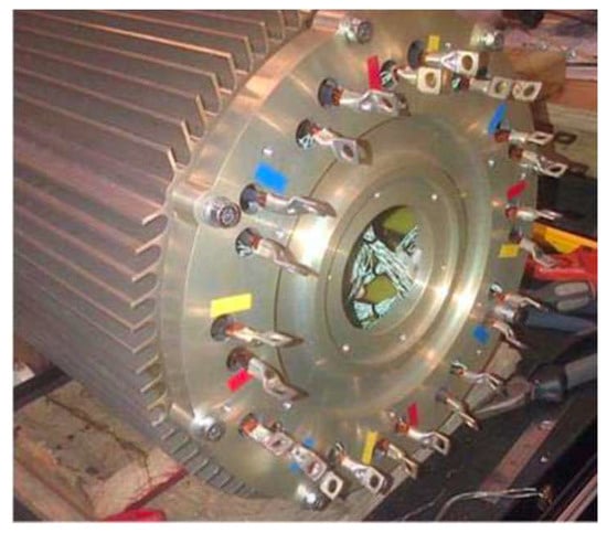
Figure 1.
A fin-cooled electric tail motor [19].
Using a water jacket is another important housing cooling method. The heat generated inside the machine is transported to the cooling jacket through conduction and convection, and then it is dissipated to the outside environment by the coolant. Figure 2 shows the configuration of a jacket-cooled electric motor, for which the series number of the water channel was optimized in [24] to realize the best performance of heat dissipation as well as mechanical protection. The coolant inside the water jacket can flow at different directions [25], such as circumferential, axial, and spiral, as shown in Figure 3. The circumferential one is a hollow jacket, which encloses the stator and allows the coolant water to circulate along the circumferential direction. In the axial water jacket, axial channels and ribs are introduced to make the coolant flow along the axial direction. The spiral water jacket can be considered as a combination of the circumferential water jacket and axial water jacket. Compared to circumferential and axial jackets, the spiral cooling jacket has superior thermal performance demonstrated by the increased heat transfer coefficient, larger surface area, and lower winding temperature. In [26], water jacket cooling was employed on a PM synchronous in-wheel motor. The optimization on the jacket configuration showed that the axial jacket can achieve a 1.6-times convection heat transfer coefficient for the circumferential counterpart. Generally, the enclosed housing cooling method has a good function to control overall temperature increases, but it has limitations in terms of cooling internal hotspots.
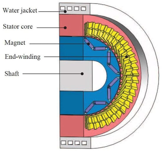
Figure 2.
An electric motor cooled by water jacket [24].
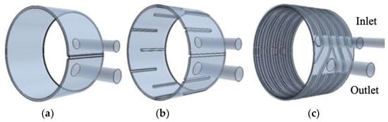
Figure 3.
Cooling water jacket concepts [25]. (a) Circumferential. (b) Axial. (c) Spiral.
3. Enhanced Conductive Cooling
The inside hotspots of electrical machines are most likely to appear on armature windings and the stator core, which generate copper loss and iron loss, respectively. One major obstacle of cooling interior hotspots is the low thermal conductivity of the air-gap and winding insulation, which makes it difficult to transport heat from armature winding to the housing. Inserting heat conductors into the slot is an effective method to increase heat dissipation efficiencies. Figure 4 shows an aircraft wheel actuator with an inserted T-shaped copper path in each stator slot [27]. Because of the high thermal conductivity of copper, the T-shaped path is more effective to transfer the heat generated by in-slot winding to the stator core. A similar idea was implemented in a tubular linear permanent magnet machine [28], which demonstrated a reduction of approximately 40% in the slot hot-spot temperature for the same current loading. The increased capability of heat dissipation enables the electrical machines to be designed with larger current densities and achieve higher torque/power density accordingly. In [29], heat guides were inserted between the two layers of the in-slot windings, as shown in Figure 5. The heat guides have similar functions as the T-shaped copper plate, which demonstrated an improvement of 55–85% heat transfer from the in-slot windings to the stator core.
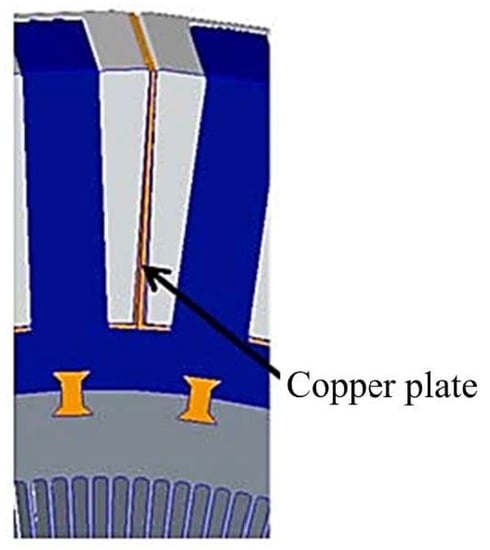
Figure 4.
An aircraft wheel actuator with inserted T-shaped copper paths [27].
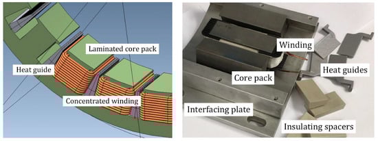
Figure 5.
A concentrated winding electrical machine with heat guide [29].
In addition to in-slot windings, end-windings also generate a significant part of heat, especially for electrical machines with distributed windings. The gap between the end-windings and the housing makes thermal management a challenging problem. Employing potting materials that have a high thermal conductivity is an effective method [30], as shown in Figure 6. The potting material can significantly increase heat conduction’s efficiency. In addition to remove heat from the end-windings, the potting material also prevents rotor magnets from being over heated. The investigation on a 100 kW radial flux PM electrical machine showed that potting materials can reduce the temperature of end-windings and rotor magnets by 7 K and 6 K, respectively. Similarly, an extended end-winding cooling insert was developed for electrical machines with concentrated windings [31], as shown in Figure 7. The stator lamination was extended in both axial directions, and the thermal conduct surface between the stator windings and the machine housing significantly increased. Compared with a reference cooling system which employs epoxy potting material on the end-windings, the extended end-winding insert was able to increase continuous current densities from 19.0 A/mm2 to 26.5 A/mm2; hence, a significant improvement of power density can be achieved accordingly. It should be noted that materials with high thermal conductivity generally also have high electrical conductivity; therefore, enhanced conductive cooling may introduce additional eddy current loss. Meanwhile, the potting material and cooling insert will increase the weight of electrical machines as well.
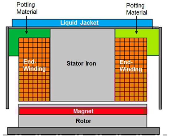
Figure 6.
A permanent magnet motor with potting materials [30].
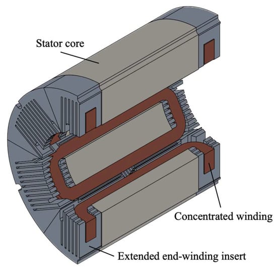
Figure 7.
Cross section of a machine stator with extended end-winding insert [31].
4. Embedded Heat Pipe Cooling
In enhanced conductive cooling systems, the heat is firstly transported to the stator core and machine frame, and then dissipated by the cooling fins or the coolant in the water jackets. The heat dissipation process is indirect. Embedding heat pipes at the positions of hotspots is more efficient, which removes the heat directly from the hotspots. Figure 8 shows a thermal design with an annular heat pipe directly installed on the end-windings [32]. The end-winding temperature can be reduced by 25% when the heat pipe was employed on one side of the end-windings, and further temperature reductions can be achieved when both sides of end-windings are equipped with the heat pipe. The heat pipe can be constructed using different materials, such as metal, polymer, composite, and silicone rubber, among which silicone rubber demonstrated the best cooling performance. A U-shaped heat pipe was developed in [33], and one leg was inserted into the stator slots and the other leg was inserted into the fins, as shown in Figure 9. Different from the in-slot copper plate in conductive cooling systems, the U-shaped heat pipe transferred heat from in-slot windings to the ambient air axially. A maximum winding temperature less than 100 degrees was observed on a 167 W machine when the current density was 12.5 A/mm2.
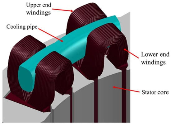
Figure 8.
Split end-winding with a cooling pipe [32].
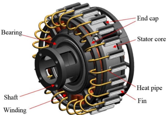
Figure 9.
An electrical machine with U-shaped heat pipes [33].
Various heat pipes have been developed to remove heat from the in-slot windings. In [34], axial cooling channels were introduced to the slot openings of a switched reluctance machine, as shown in Figure 10. Instead of passing through the stator core to the machine frame, the heat of the windings can be directly removed axially through the cooling channels. The simulation results showed that a maximum temperature reduction of 90 degrees and 65 degrees can be achieved on the coil and the stator lamination, respectively. A direct winding heat exchanger was developed in [35], which used a microfeature-enhanced heat exchanger that was inserted between the stator winding bundles, as shown in Figure 11. This technique is especially suitable for concentrated winding electrical machines. The microchannels significantly reduced the thermal resistance between the windings and the ambient; hence, the current density can be substantially increased with the same winding insulation. For class F insulation, a maximum current density of 24.7 A/mm2 and 40 A/mm2 can be achieved for steady-state and transient conditions, respectively. Slot water jacket cooling systems for hairpin windings were investigated in [36], as illustrated in Figure 12. The water jackets can be installed at the slot openings or at the bottom of the slots. To fit the installation of water jackets, either the winding height was reduced to keep the same slot area or the slot depth was increased to maintain the original winding size. The investigation on an induction motor and a PM motor revealed that placing a water jacket at the slot opening produced better thermal performance due to the proximity of the coolant to the machine’s hotspots.
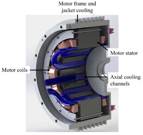
Figure 10.
A thermal system with axial cooling channels at slot openings [34].
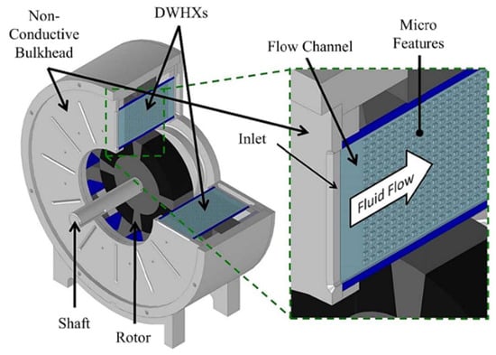
Figure 11.
An electrical machine with in-slot microchannel heat exchangers [35].
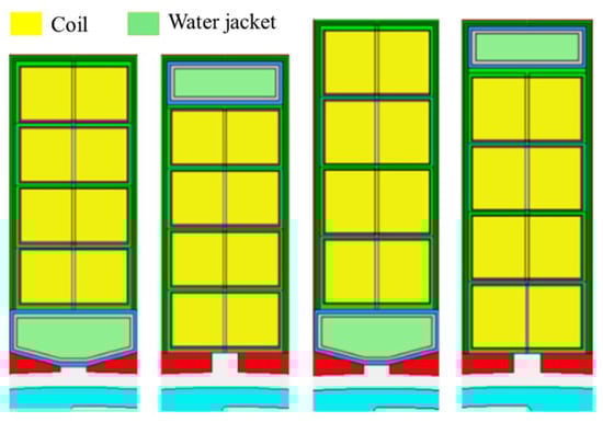
Figure 12.
Four different slot designs with water jackets [36].
Figure 13 shows the schematic of hollow conductors developed in [37], in which the phase change material (PCM) was placed inside the hollow conductors. Because of the significant capability of transferring energy of PCM, this technique resulted in a reduction of 8% in winding temperature increases and a 18% decrease in winding weight. Similarly, a direct liquid cooling system was developed in [38] for an axial-flux PM machine, as shown in Figure 14. Helical tooth coil winding was employed, which was formed from a hybrid conductor comprising a stainless-steel coolant conduit tightly wrapped with a stranded Litz wire. Although the cooling channel occupied a certain area of the wire, the torque density of the machine can still be substantially improved since the current density can be increased 3.5 times. The investigations on a proof-of-concept showed a temperature reduction of more than 50 degrees when compared with indirect cooling systems. The problem of this design is that the integrated cooling channel increases the bending radius of the windings, which makes the end-windings very long and leads to a winding proportion that is not useful accordingly.
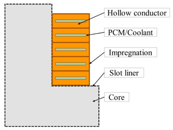
Figure 13.
Schematic of hollow conductors [37].
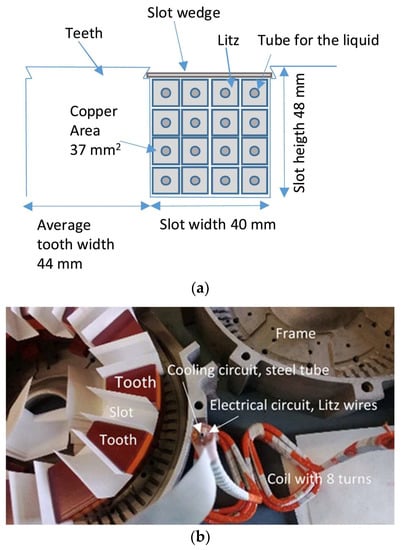
Figure 14.
Configuration of an axial-flux permanent magnet machine [38]. (a) Slot configuration; (b) stator configuration.
The stator core is the major heat conductor between the windings and the machine frame. Meanwhile, stator core loss generates a significant part of heat. Therefore, the stator core may suffer from a high temperature increase, particularly for high-speed machines for which their high frequencies greatly increases core losses. Figure 15 shows the structure of a linear PM machine, which employed a cooling channel with uniformly distributed water pipes in the stator yoke [39]. Under the same limitation of a temperature increase in windings, a 2.76-times result of the original thrust force density can be achieved due to the substantial heat dissipation capabilities of the water pipes. The water pipes contributed to the cooling of magnets as well, and a temperature reduction of 72 K was observed, which has a significant value in protecting PMs from being demagnetized by high temperatures.
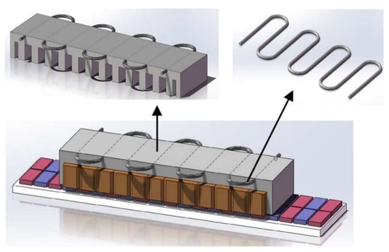
Figure 15.
Structure of linear permanent magnet machine with cooling channel in the stator core [39].
5. Direct Oil Cooling
In order to achieve full contact between the stator and the coolant, a semi-flooded oil cooling system has been proposed for high-power-density electrical machines [40], as shown in Figure 16. An oil sleeve was implemented in the air-gap, and the electrical machines were separated into two enclosed chambers: a stator chamber formed by the oil sleeve, two end flanges, and the machine frame; and a rotor chamber formed by the rotor shaft, two end flanges, and the oil sleeve. This electrical machine was directly coupled with a gear box, for which its high-pressure lubricant oil was used as the coolant and no additional oil supply system was needed. The oil was injected into the stator chamber through the holes around the end-windings and impinged on the end-windings directly. In order to minimize the impact on electromagnetic performance, the cooling channels at the stator core were created close to the outer surface. The oil was forced to pass through the cooling channels and then cooled the stator core and coils. This semi-flooded oil cooling system allowed the coolant have complete contact with the windings and stator core; hence, they had higher cooling efficiencies. The oil-flooded cooling method can be applied to axial-flux machines as well, as reported in [41], in which a glass fiber casing was used to enclose the stator, and this allowed oil to be injected into the stator chamber and to have direct contact with windings and core. A temperature reduction of 13 degrees at the hotspot was observed when compared with the original machine without oil-flooded cooling.
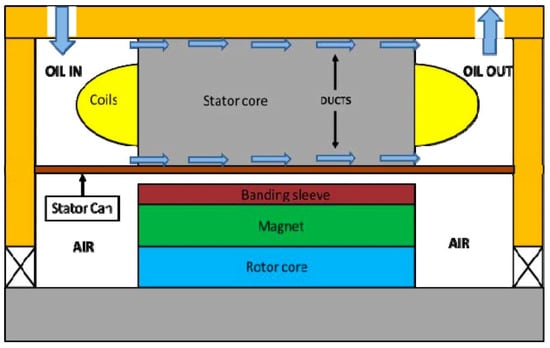
Figure 16.
Schematic of a semi-flooded oil cooling system [40].
Instead of cooling the entire stator, Figure 17 shows the schematic of direct oil cooling for the end-windings of core-wound Torus-type machines [42]. An external fiberglass cover, as shown in light green in Figure 17b, was used to seal the end-windings and avoid the oil from leaking into the air-gap. The outer end-windings were specially designed to channel an axial flow of oil and to maximize the heat exchange surface to achieve an optimal heat extraction accordingly. In this cooling system, the heat generated by the copper loss only flows through the copper and enamel before reaching the oil, and thermal resistance was significantly reduced. Compared with the indirect water cooling, this direct oil cooling method can achieve heat extraction capabilities up to 2.87 times, and the torque and power densities were doubled when it was applied to an axial-flux permanent magnet machine.
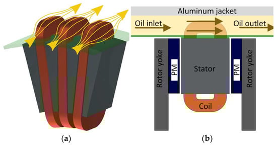
Figure 17.
Schematic of the direct oil cooling for the end-winding [42]. (a) Slot configuration; (b) axial cross section.
Recently, hairpin windings have attracted increasing attention in electric vehicle propulsion areas due to the advantages of a high-fill factor, reduced manufacturing time, and shorter end-windings. The conductors of hairpin windings are precisely arranged, and the gap between the conductors of end-windings is regularly and accurately defined. This geometric feature introduces new challenges and opportunities for heat dissipation. Oil spray cooling is ideal for the cooling of hairpin windings, which can achieve a good balance between the heat dissipation, fluid inventory, and robustness. Figure 18 shows two examples of oil spray cooling. The oil can be injected through the nozzle close to the housing or through a hollow shaft, which directly removes heat from the end-windings. Therefore, oil spray cooling can achieve a much higher convective heat transfer coefficient than air cooling. Compared with water jacket cooling, oil spray cooling can almost double the current density and power of electrical machines [43]. A 3-D lumped parameter thermal network (LPTN) of the oil spray cooled hairpin windings was proposed in [44], which considered the slot configuration, winding connection, and sprayed oil characteristics. This LPTN had been validated through experimental investigations and can be used as a good reference for electrical machine researchers to investigate the thermal performance of such windings. The estimation of heat transfer coefficient of oil spray cooling system was investigated in [45], which was based on reduced-parameter models that can be easily used by other electrical machines.
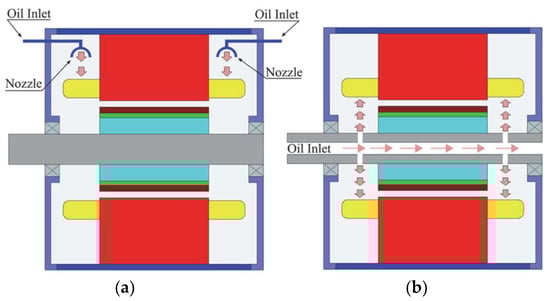
Figure 18.
Schematics of oil spray cooling arrangements [43]. (a) Oil injected by a single nozzle on top of the end-winding. (b) Oil injected through a hollow shaft.
6. Enhanced Rotor Cooling
All the aforementioned cooling methods focused on the cooling of the stator, for which its copper loss and core loss are the major heat sources of electrical machines. However, it is also significant for managing the thermal conditions of the rotor, especially for PM machines since PMs may inevitably be demagnetized by high temperatures. Forced air cooling is the most popular method of rotor cooling, in which a fan is implemented co-axially with the rotor and takes away heat when the rotor rotates. Figure 19 shows the configuration of an axial flux PM machine with a centrifugal fan attached on the rotor [46]. This fan cooling was used as a secondary cooling method in addition to water cooling for the purpose of boosting machine performances even further. The rotor was designed with an opening at the center and a single outlet on the radial cover. When the rotor rotates, a pressure gradient will be created and the air will flow inside through the center inlet and flow outside through the side outlet. The air flow will remove heat from the rotor and increase the machine’s continuous power by 43% and the torque by 20%.
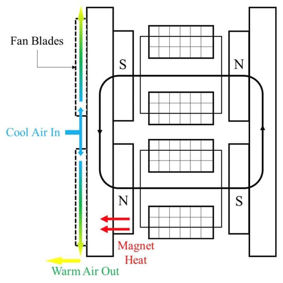
Figure 19.
Configuration of an axial flux permanent magnet machine with a centrifugal fan attached on the rotor [46].
Another rotor cooling method is to employ hollow shafts with inside cooling channels, which has a superior heat dissipation performance because the coolant can remove heat from the rotor directly. Figure 20 shows the configuration of a hybrid cooling system with both hollow shaft rotor cooling and housing cooling [47]. The coolant flowed inside the machine through the inlet and then circulated in the housing jacket, end cap, and hollow shaft before exiting through the outlet. Compared with air-cooled and housing jacket-cooled designs, this hybrid cooling system could reduce the coil temperature by 50% and 38%, respectively, and decrease the outer stator’s temperature by 42% and 10%, respectively. The temperature reduction leads to a larger current density that can be applied in the windings, and the torque and power densities can be improved accordingly. The major challenge is that hollow shaft will reduce the mechanical strength, and excellent sealing is needed to prevent oil leakage.
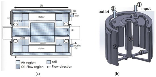
Figure 20.
Hollow shaft rotor cooling [47]. (a) 2D coolant path; (b) 3D diagram.
7. Summary and Conclusions
Thermal management technologies have a great impact on the operation and performance of electrical machines. This paper reviews advances in the thermal management technologies of electrical machines, with a specific focus on cooling system configurations. For the literature reporting the same configuration, only the representative ones are cited and discussed. The findings in this paper provide good guidance for cooling system designs and can inspire new ideas on the research and development of future thermal management technologies of electrical machines. Overall, the heat of electrical machines is mainly dissipated through conduction and convection. Different cooling systems have their unique features, and various factors should be considered, such as the machine configuration, operation environment, and cost, to achieve the best overall performance. Most research focused on stator cooling, since stator core loss and winding copper loss are the principal heat sources of electrical machines. Enhanced rotor cooling is mainly implemented on PM machines to protect the magnets from being demagnetized by the high temperature. The summary and comparison of different cooling systems are provided in Table 1.

Table 1.
Comparison of different cooling systems.
The key parameters of different cooling systems are listed in Table 2, which aims to provide a more quantitative comparison. There are some unavailable parameters in the references that are notated as “N/A”. One can observe that the enclosed housing cooling system has the poorest hear transfer coefficient (HTC). By comparison, using direct oil cooling brings better thermal conditions as the oil has higher HTC than air. However, enclosed housing cooling is generally used as the primary thermal management technique of electrical machines, because it does not influence the machines’ internal structure; therefore, it is is easy to implement. The research mainly focuses on increasing the heat dissipation area of cooling fins, designing novel configurations of water jackets, and optimizing water flow inside the jackets for the purpose of increasing heat dissipation efficiency. This cooling method shows a good performance in controlling the overall temperature increase and can be implemented in almost all types of electrical machines. However, it has limitations in cooling the inside of hotspots.
Table 2.
Key parameters of different cooling systems.
Enhanced conductive cooling generally serves as a secondary thermal management technique in addition to enhanced housing cooling, which employs materials with high thermal conductivity to reduce thermal resistance between the heat source and the machine frame. Since materials with high thermal conductivity usually have good electrical conductivity, this method may introduce additional eddy current loss.
Embedded heat pipe cooling and direct coil cooling aim to remove heat from the source directly. The heat pipe can be designed into flexible configurations and be implemented at different locations, such as the stator core, slots, in-slot windings, and end-windings. With a proper design, the cooling oil can reach all hotspots as well. Therefore, both methods have excellent heat dissipation capabilities. The challenge is that heat pipe increases the complexity of the structure, and superior sealing is needed in the direct oil cooling system to prevent oil leakage.
Author Contributions
Q.W. contributed the major content of this paper. Y.W., S.N. and X.Z. participated in the writing and revision of the paper. All authors have read and agreed to the published version of the manuscript.
Funding
This research received no external funding.
Institutional Review Board Statement
Not applicable.
Informed Consent Statement
Not applicable.
Data Availability Statement
Not applicable.
Conflicts of Interest
The authors declare no conflict of interest. The funders had no role in the design of the study; in the collection, analyses, or interpretation of data; in the writing of the manuscript; or in the decision to publish the results.
References
- Cheng, M.; Sun, L.; Buja, G.; Song, L. Advanced Electrical Machines and Machine-Based Systems for Electric and Hybrid Vehicles. Energies 2015, 8, 9541–9564. [Google Scholar] [CrossRef] [Green Version]
- Kumar, L.; Jain, S. Electric Propulsion System for Electric Vehicular Technology: A Review. Renew. Sustain. Energy Rev. 2014, 29, 924–940. [Google Scholar] [CrossRef]
- Ho, S.L.; Wang, Q.; Niu, S.; Fu, W.N. A Novel Magnetic-Geared Tubular Linear Machine with Halbach Permanent-Magnet Arrays for Tidal Energy Conversion. IEEE Trans. Magn. 2015, 51, 1–4. [Google Scholar]
- Ozturk, S.; Fthenakis, V.; Faulstich, S. Failure Modes, Effects and Criticality Analysis for Wind Turbines Climatic Regions and Comparing Geared and Direct Drive Wind. Energies 2018, 11, 2317. [Google Scholar] [CrossRef]
- Xie, P.; Vakil, G.; Gerada, C. Electric Drive Systems with Long Feeder Cables. IET Electr. Power Appl. 2020, 14, 16–30. [Google Scholar] [CrossRef]
- Saghin, S.M.; Ghaheri, A.; Shirzad, H.; Afjei, E. Performance Optimisation of a Segmented Outer Rotor Flux Switching Magnet Motor for Direct Drive Washing Machine Application. IET Electr. Power Appl. 2021, 15, 1574–1587. [Google Scholar] [CrossRef]
- Wang, Q.; Niu, S. Overview of Flux-Controllable Machines: Electrically Excited Machines, Hybrid Excited Machines and Memory Machines. Renew. Sustain. Energy Rev. 2017, 68, 475–491. [Google Scholar] [CrossRef]
- Wang, Q.; Niu, S. A Novel DC-Coil-Free Hybrid-Excited Machine with Consequent-Pole PM Rotor. Energies 2018, 11, 700. [Google Scholar] [CrossRef] [Green Version]
- Mao, Y.; Niu, S.; Wang, Q. Design and Optimization of a Slot-PM-Assisted Doubly-Salient Machine Based on Saturation Assuaging. Chin. J. Electr. Eng. 2021, 7, 65–72. [Google Scholar] [CrossRef]
- Wang, Q.; Niu, S. A Novel Hybrid-Excited Flux Bidirectional Modulated Machine for Electric Vehicle Propulsion. In Proceedings of the 2016 IEEE Vehicle Power and Propulsion Conference (VPPC), Hangzhou, China, 17–20 October 2016; pp. 1–6. [Google Scholar]
- Pothi, N.; Zhu, Z.Q.; Afinowi, I.A.A.; Lee, B.; Ren, Y. Control Strategy for Hybrid-Excited Switched-Flux Permanent Magnet. IET Electr. Power Appl. 2015, 9, 612–619. [Google Scholar] [CrossRef]
- Ullah, N.; Khan, F.; Basit, A.; Shahzad, M. Experimental Validations of Hybrid Excited Linear Flux Switching Machine. Energies 2021, 14, 7274. [Google Scholar] [CrossRef]
- Ali, Q.; Hussain, A.; Baloch, N.; Kwon, B. Design and Optimization of a Brushless Wound-Rotor Vernier Machine. Energies 2018, 11, 317. [Google Scholar] [CrossRef] [Green Version]
- Liang, D.; Zhu, Z.Q.; Zhang, Y.; Feng, J.; Guo, S.; Li, Y.; Wu, J.; Zhao, A. A Hybrid Lumped-Parameter and Two-Dimensional Analytical Thermal Model for Electrical Machines. IEEE Trans. Ind. Appl. 2021, 57, 246–258. [Google Scholar] [CrossRef]
- Rostami, N.; Feyzi, M.R.; Pyrhonen, J.; Parviainen, A.; Niemela, M. Lumped-Parameter Thermal Model for Axial Flux Permanent Magnet Machines. IEEE Trans. Magn. 2013, 49, 1178–1184. [Google Scholar] [CrossRef]
- Graffeo, F.; Vaschetto, S.; Miotto, A.; Carbone, F.; Tenconi, A.; Cavagnino, A. Lumped-Parameters Thermal Network of PM Synchronous Machines for Automotive Brake-by-Wire Systems. Energies 2021, 14, 5652. [Google Scholar] [CrossRef]
- Zhou, K.; Pries, J.; Hofmann, H. Computationally Efficient 3-D Finite-Element-Based Dynamic Thermal of Electric Machines. IEEE Trans. Transp. Electrif. 2015, 1, 138–149. [Google Scholar] [CrossRef]
- Boglietti, A.; Cossale, M.; Popescu, M.; Staton, D.A. Electrical Machines Thermal Model: Advanced Calibration Techniques. IEEE Trans. Ind. Appl. 2019, 55, 2620–2628. [Google Scholar] [CrossRef]
- Mellor, P.H.; Yon, J.; Baker, J.L.; North, D.; Booker, J.D. Electromagnetic and Thermal Coupling within a Fault-Tolerant Aircraft Propulsion Motor. In Proceedings of the 2017 IEEE International Electric Machines and Drives Conference, Miami, FL, USA, 21–24 May 2017. [Google Scholar]
- Valenzuela, M.A.; Tapia, J.A. Heat Transfer and Thermal Design of Finned Frames for TEFC Variable-Speed Motors. IEEE Trans. Ind. Electron. 2008, 55, 3500–3508. [Google Scholar] [CrossRef]
- Ulbrich, S.; Kopte, J.; Proske, J. Cooling Fin Optimization on a TEFC Electrical Machine Housing Using a 2-D Conjugate Heat Transfer Model. IEEE Trans. Ind. Electron. 2018, 65, 1711–1718. [Google Scholar] [CrossRef]
- Gilson, G.M.; Pickering, S.J.; Hann, D.B.; Gerada, C. Piezoelectric Fan Cooling: A Novel High Reliability Electric Machine Thermal Management Solution. IEEE Trans. Ind. Electron. 2013, 60, 4841–4851. [Google Scholar] [CrossRef]
- Gilson, G.M.; Pickering, S.J.; Hann, D.B.; Gerada, C. High Reliability Piezoelectric Fan Cooling for Electric Machine Thermal Management. In Proceedings of the 6th IET International Conference on Power Electronics, Machines and Drives (PEMD 2012), Bristol, UK, 27–29 March 2012; pp. 1–6. [Google Scholar]
- Zhang, B.; Qu, R.; Member, S.; Fan, X.; Wang, J.; Analysis, A.E.F. Thermal and Mechanical Optimization of Water Jacket of Permanent Magnet Synchronous Machines for EV Application. In Proceedings of the 2015 IEEE International Electric Machines & Drives Conference, Coeur d’Alene, ID, USA, 10–13 May 2015. [Google Scholar]
- Yang, X.; Fatemi, A.; Nehl, T.; Hao, L.; Zeng, W.; Parrish, S. Comparative Study of Three Stator Cooling Jackets for Electric Machine of Mild Hybrid Vehicle. IEEE Trans. Ind. Appl. 2021, 57, 1193–1201. [Google Scholar] [CrossRef]
- Liang, P.; Chai, F.; Shen, K.; Liu, W. Thermal Design and Optimization of a Water-Cooling Permanent Magnet Synchronous in-Wheel Motor. In Proceedings of the 2019 22nd International Conference on Electrical Machines and Systems (ICEMS), Harbin, China, 11–14 August 2019; pp. 1–6. [Google Scholar]
- Xu, Z.; Galea, M.; Tighe, C.; Hamiti, T.; Gerada, C.; Pickering, S.J. Mechanical and Thermal Management Design of a Motor for an Aircraft Wheel Actuator. In Proceedings of the 2014 17th International Conference on Electrical Machines and Systems, ICEMS 2014, Hangzhou, China, 22–25 October 2014; pp. 3268–3273. [Google Scholar]
- Galea, M.; Gerada, C.; Raminosoa, T.; Wheeler, P. A Thermal Improvement Technique for the Phase Windings of Electrical Machines. IEEE Trans. Ind. Appl. 2012, 48, 79–87. [Google Scholar] [CrossRef]
- Wrobel, R.; Hussein, A. A Feasibility Study of Additively Manufactured Heat Guides for Enhanced Heat Transfer in Electrical Machines. IEEE Trans. Ind. Appl. 2020, 56, 205–215. [Google Scholar] [CrossRef] [Green Version]
- Polikarpova, M.; Lindh, P.M.; Tapia, J.A.; Pyrhönen, J.J. Application of Potting Material for a 100 KW Radial Flux PMSM. In Proceedings of the Proceedings—2014 International Conference on Electrical Machines, Berlin, Germany, 2–5 September 2014; pp. 2146–2151. [Google Scholar]
- Vansompel, H.; Sergeant, P. Extended End-Winding Cooling Insert for High Power Density Electric Machines with Concentrated Windings. IEEE Trans. Energy Convers. 2020, 35, 948–955. [Google Scholar] [CrossRef]
- Madonna, V.; Walker, A.; Giangrande, P.; Serra, G.; Gerada, C.; Galea, M. Improved Thermal Management and Analysis for Stator End-Windings of Electrical Machines. IEEE Trans. Ind. Electron. 2019, 66, 5057–5069. [Google Scholar] [CrossRef]
- Zhang, X.; Zhang, C.; Fu, P.; Zhang, C.; Li, L. A Novel Cooling Technique for the Windings of High-Torque-Density Permanent Magnet Machines. In Proceedings of the 2018 21st International Conference on Electrical Machines and Systems (ICEMS), Jeju, Korea, 7–10 October 2018; pp. 332–337. [Google Scholar]
- Rhebergen, C.; Bilgin, B.; Emadi, A.; Rowan, E.; Lo, J. Enhancement of Electric Motor Thermal Management through Axial Cooling Methods: A Materials Approach. In Proceedings of the 2015 IEEE Energy Conversion Congress and Exposition (ECCE), Montreal, QC, Canada, 20–24 September 2015; pp. 5682–5688. [Google Scholar]
- Semidey, S.A.; Mayor, J.R. Experimentation of an Electric Machine Technology Demonstrator Incorporating Direct Winding Heat Exchangers. IEEE Trans. Ind. Electron. 2014, 61, 5771–5778. [Google Scholar] [CrossRef]
- Venturini, G.; Volpe, G. Slot Water Jacket Cooling System for Traction Electrical Machines with Hairpin Windings: Analysis and Comparison. In Proceedings of the 2021 IEEE International Electric Machines & Drives Conference (IEMDC), Hartford, CT, USA, 17–20 May 2021. [Google Scholar]
- Ayat, S.; Serghine, C.; Klonowski, T.; Yon, S.; Mutabazi, A.; McDaniel, S. The Use of Phase Change Material for the Cooling of Electric Machine Windings Formed with Hollow Conductors. In Proceedings of the 2019 IEEE International Electric Machines and Drives Conference, San Diego, CA, USA, 12–15 May 2019; pp. 1195–1201. [Google Scholar]
- Lindh, P.; Petrov, I.; Jaatinen-Varri, A.; Gronman, A.; Martinez-Iturralde, M.; Satrústegui, M.; Pyrhonen, J. Direct Liquid Cooling Method Verified with an Axial-Flux Permanent-Magnet Traction Machine Prototype. IEEE Trans. Ind. Electron. 2017, 64, 6086–6095. [Google Scholar] [CrossRef]
- Lu, Q.; Zhang, X.; Chen, Y.; Huang, X.; Ye, Y.; Zhu, Z.Q. Modeling and Investigation of Thermal Characteristics of a Water-Cooled Permanent-Magnet Linear Motor. IEEE Trans. Ind. Appl. 2015, 51, 2086–2096. [Google Scholar] [CrossRef]
- Xu, Z.; La Rocca, A.; Arumugam, P.; Pickering, S.J.; Gerada, C.; Bozhko, S.; Gerada, D.; Zhang, H. A Semi-Flooded Cooling for a High Speed Machine: Concept, Design and Practice of an Oil Sleeve. In Proceedings of the IECON 2017-43rd Annual Conference of the IEEE Industrial Electronics Society, Beijing, China, 29 October–1 November 2017. [Google Scholar]
- Camilleri, R.; Beard, P.; Howey, D.A.; McCulloch, M.D. Prediction and Measurement of the Heat Transfer Coefficient in a Direct Oil-Cooled Electrical Machine With Segmented Stator. IEEE Trans. Ind. Electron. 2018, 65, 94–102. [Google Scholar] [CrossRef]
- Marcolini, F.; de Donato, G.; Capponi, F.G.; Caricchi, F. Direct Oil Cooling of End-Windings in Torus-Type Axial-Flux Permanent-Magnet Machines. IEEE Trans. Ind. Appl. 2021, 57, 2378–2386. [Google Scholar] [CrossRef]
- Liu, C.; Xu, Z.; Gerada, D.; Li, J.; Gerada, C.; Chong, Y.C.; Popescu, M.; Goss, J.; Staton, D.; Zhang, H. Experimental Investigation on Oil Spray Cooling with Hairpin Windings. IEEE Trans. Ind. Electron. 2020, 67, 7343–7353. [Google Scholar] [CrossRef]
- Zhang, F.; Gerada, D.; Xu, Z.; Liu, C.; Zhang, H.; Zou, T.; Chong, Y.C.; Gerada, C. A Thermal Modeling Approach and Experimental Validation for an Oil Spray-Cooled Hairpin Winding Machine. IEEE Trans. Transp. Electrif. 2021, 7, 2914–2926. [Google Scholar] [CrossRef]
- Liu, C.; Gerada, D.; Xu, Z.; Chong, Y.C.; Michon, M.; Goss, J.; Li, J.; Gerada, C.; Zhang, H. Estimation of Oil Spray Cooling Heat Transfer Coefficients on Hairpin Windings with Reduced-Parameter Models. IEEE Trans. Transp. Electrif. 2021, 7, 793–803. [Google Scholar] [CrossRef]
- Fawzal, A.S.; Cirstea, R.M.; Gyftakis, K.N.; Woolmer, T.J.; Dickison, M.; Blundell, M. Fan Performance Analysis for Rotor Cooling of Axial Flux Permanent Magnet Machines. IEEE Trans. Ind. Appl. 2017, 53, 3295–3304. [Google Scholar] [CrossRef]
- Lee, K.H.; Cha, H.R.; Kim, Y.B. Development of an Interior Permanent Magnet Motor through Rotor Cooling for Electric Vehicles. Appl. Therm. Eng. 2016, 95, 348–356. [Google Scholar] [CrossRef]
- Shams Ghahfarokhi, P.; Podgornovs, A.; Kallaste, A.; Cardoso, A.J.M.; Belahcen, A.; Vaimann, T.; Asad, B.; Tiismus, H. Determination of Heat Transfer Coefficient from Housing Surface of a Totally Enclosed Fan-Cooled Machine during Passive Cooling. Machines 2021, 9, 120. [Google Scholar] [CrossRef]
- Shams Ghahfarokhi, P.; Kallaste, A.; Podgornovs, A.; Belahcen, A.; Vaimann, T.; Asad, B. Determination of Heat Transfer Coefficient of Finned Housing of a TEFC Variable Speed Motor. Electr. Eng. 2021, 103, 1009–1017. [Google Scholar] [CrossRef]
- Huang, Z.; Nategh, S.; Lassila, V.; Alaküla, M.; Yuan, J. Direct Oil Cooling of Traction Motors in Hybrid Drives. In Proceedings of the 2012 IEEE International Electric Vehicle Conference, Greenville, SC, USA, 4–8 March 2012; pp. 1–8. [Google Scholar]
- Camilleri, R.; Howey, D.A.; McCulloch, M.D. Predicting the Temperature and Flow Distribution in a Direct Oil-Cooled Electrical Machine with Segmented Stator. IEEE Trans. Ind. Electron. 2015, 63, 82–91. [Google Scholar] [CrossRef] [Green Version]
- Kang, M.; Guo, L.; Wang, H.; Wang, Z.; Xia, C. An Improved Rotor Cooling Structure of IPMSM. In Proceedings of the 2019 22nd International Conference on Electrical Machines and Systems (ICEMS), Harbin, China, 11–14 August 2019; pp. 1–6. [Google Scholar]
Publisher’s Note: MDPI stays neutral with regard to jurisdictional claims in published maps and institutional affiliations. |
© 2022 by the authors. Licensee MDPI, Basel, Switzerland. This article is an open access article distributed under the terms and conditions of the Creative Commons Attribution (CC BY) license (https://creativecommons.org/licenses/by/4.0/).