Article

Detection of Stator Winding Faults in PMSMs Based on Second Harmonics of Phase Instantaneous Reactive Powers

1
College of Information Engineering, Beijing Institute of Petrochemical Technology, Beijing 102617, China
2
State Key Laboratory of Reliability and Intelligence of Electrical Equipment, Hebei University of Technology, Tianjin 300401, China
3
Department of Electrical and Computer Engineering, Michigan State University, East Lansing, MI 48824, USA
4
College of Electrical Engineering, Zhejiang University, Hangzhou 310027, China
*
Author to whom correspondence should be addressed.
Energies 2022, 15(9), 3248; https://doi.org/10.3390/en15093248
Submission received: 1 April 2022 / Revised: 23 April 2022 / Accepted: 27 April 2022 / Published: 28 April 2022
(This article belongs to the Section F: Electrical Engineering)

Abstract

:
Reliable stator winding faults diagnosis is important for machine drives. This work presents an inter-turn short-circuit (ITSC) winding faults detection method for permanent magnet synchronous motors (PMSMs), based on the percentage of the second harmonics in phase instantaneous reactive powers (IRPs), defined in the abc frame of reference. In particular, the proposed indicator can locate the phase with ITSC for the PMSM with neutral conductor. The feature of ITSC in phase IRP is analyzed theoretically first, and a simulation setup is established in MATLAB/Simulink using the faulty PMSM model widely used for ITSC detection. From the theoretical analysis and the simulations, the second harmonic in phase IRP is proven to be the characteristic feature for fault detection. Simulations at different operating conditions show that the percentage of the second harmonic to its dc component in phase IRP, which is the proposed indicator in this article, is more reliable than the second harmonic amplitude itself for the ITSC detection and location. Experimental tests are carried out on a 3 kW motor with ITSC to investigate the effectiveness of the proposed indicator under different working conditions.

1. Introduction

Permanent magnet synchronous motors (PMSMs) are widely used in modern industrial production due to their high efficiency and high power density. With the increased demand for high power and torque density, the motor will work in an environment with higher mechanical, thermal and electrical stress, which further increases the possibility of failure. Winding faults due to insulation degradation and failure between turns, leading to short circuits (stator inter-turn short-circuits, ITSCs) are among the most common faults in PMSMs. After ITSC, due to the induced voltage cross the shorted turns, a high fault current (also called circulating current), is generated in the short-circuit path, which further aggravates the degradation of the turn-to-turn insulation. The fault current increases rapidly, which seriously affects the normal operation of the motor and always leads to a catastrophic failure in a short time [1,2]. It is difficult to reduce the damage to the PMSMs when there is an ITSC, because the magnets cannot be switched off.
Machine currents and voltages signature analysis (MCSA and MVSA) have proven to be efficient techniques for fault detection because of their non-invasive feature and being easy to access. The current measurements are essential for machine control and the voltages can also be acquired from voltage sensors. As an alternative to the measurement of voltages, the controller reference voltages have been proved to be applicable in faults detection [2]. The harmonics introduced by the ITSCs in currents and magnetic field of air gap are determined by the fundamental frequency of the motor, the number of pole pairs, the motor inherent parameters [3], and the amplitudes of characteristic harmonics are positively correlated with the fault severity. In [4], the ITSC was detected by the stator currents, and the sideband components of the stator current were used to evaluate the fault severity. Regardless of the machine winding configuration, the third harmonics of the stator currents were credible for ITSCs detection, and the percentage of shorted turns detectable is as low as 2–3% [5]. The zero-sequence voltage component and the zero-sequence current component were used to diagnose the ITSCs fault of star-connected and delta-connected PMSMs, respectively [6]. The proposed fault indicator based on short-circuit current realized the detection of ITSCs, fault phase location and fault severity assessment. The inter-turn faults of the stator windings with 50% phase turns were detected by extracting the amplitude of the second harmonic in the reference voltages [7]; however, the performance of detection for the low percentage of short-circuits was not studied in detail. ITSCs in PMSM can be detected by the dc components and second harmonics in reference voltages [8]. In the synchronous frame of reference, the changes in the currents vector amplitude and angle were used to detect the stator winding faults and distinguish them from demagnetization faults [9], and the second harmonic components in the voltages and currents were used for ITSCs fault detection [10]. However, the relationship between the characteristic components and the fault severity will be affected by the regulator parameters [11]. In [12], the detection and classification of ITSC were achieved by detecting the amplitudes of first 15 harmonics in measured currents and commanded voltages. The relationship between the fault characteristics and the voltages drop of the winding with ITSC was analyzed in [13], and the faulty phase was detected by comparing the residual components in the three-phase voltages. In addition, the third negative and positive harmonics in the space vectors of current and voltage in the synchronous frame of reference [14], the Park’s Vectors of current and voltage [4], the back-induced electromotive forces (EMFs) and the impedance [15,16] were also used for ITSCs detection.
The fault characteristics are usually reflected in various parameters of the drive system, and the degrees of these characteristics are different. Most of the above techniques are based on the analysis of one signal, such as voltages or currents. However, due to the weak fault characteristics in the signals, especially for the incipient faults with low severity, it becomes a difficult task to recognize the fault. For ITSC with a few shorted turns, the fault information contained in voltages or currents is always not sufficient for detecting [2]. Therefore, the methods of multi-signal fusion are more effective. The fault information in currents and voltages can be weighted adaptively to the change in current controller bandwidth, and this way an ITSC indicator, incorporating fault information in both currents and voltages and robust to the current controller bandwidth, was proposed in [17]. In [18], the third harmonics of the stator currents and the dc component of the zero-sequence voltage were combined to detect the surface-mounted PMSMs ITSCs fault, the Vold–Kalman order-filtering tracking algorithm was used to track the characteristic harmonics, which improved the reliability of fault detection when the speed changes. Another combination of the characteristic in currents and voltages for ITSCs detection is instantaneous real and reactive power [1,19,20,21]. In synchronous frame of reference, instantaneous reactive power (IRP), has been reported as an effective indicator for ITSCs detection, since it contains more fault information than currents and voltages individually. For example, the second harmonic in IRP, defined in the synchronous frame of reference:
IRP = 1.5 ( v q i d v d i q )
was reported to be an effective indicator for ITSCs detection in PMSMs under motoring mode [19]. The classification and connection of the above fault detection methods, based on machine current and voltage signature analysis, are shown in Figure 1.
This article proposes a new ITSC indicator, the percentage of second harmonic to dc component in the phase IRP defined in the abc frame of reference. For three-phase PMSMs, the proposed indicator can not only detect ITSC faults, but also locate the faulty phase when the neutral is connected. The proposed indicator was first introduced in [22], where only the simulation results were presented. In this article, experiments validation is conducted, and moreover, the robustness with respect to operating conditions of the proposed indicator is evaluated and validated by coefficient of variation.

2. Reactive Power Signature Analysis

Different from the classical power definition based on the root mean square (RMS) and mean values of current and voltage, the instantaneous power is defined with their instant values. An advantage is that it is valid in the transient state, such as the load change in the case of a motor operating. Considering that the stator active power changes in a much wider range and in a faster way when compared to the reactive power, the analysis of the stator reactive power is used for fault diagnostic purposes [21].

2.1. Instantaneous Reactive Power Definition

The generalized IRP is defined as [23]:
q n t = q ¯ = q a 2 + q b 2 + q c 2
in which the phase IRPs, qabc, are defined to be the cross-product of the voltage and current vectors, shown as:
q ¯ = v ¯ × i ¯ = v a v b v c × i a i b i c = q a q b q c = v b i c v c i b v c i a v a i c v a i b v b i a
This definition is valid for three-phase three-wire system, and the original authors introduced in [23] showed that many other definitions can be deducted from (2) using different transformations.
The objective of this work is to detect ITSCs in PMSM and locate the faulty phase as much as possible. Therefore, the absolute value of the three-phase IRPs, |qa|, |qb| and |qc|, are investigated, in order to show a different phase IRP behavior among the three phases when an ITSC happens in only one of them.

2.2. ITSC Characterization

2.2.1. Case of Healthy PMSMs

Assuming the healthy PMSM is powered from a balanced three-phase voltage inverter and driving a constant load, the expressions of stator voltages and currents are modeled by the following:
v a t = 2 V cos ( ω t ) v b t = 2 V cos ( ω t 2 π / 3 ) v c t = 2 V cos ( ω t + 2 π / 3 )
i a t = 2 I cos ( ω t φ ) i b t = 2 I cos ( ω t φ 2 π / 3 ) i c t = 2 I cos ( ω t φ + 2 π / 3 )
The phase IRPs can be calculated by substituting (4) and (5) into (3), and derived the qi (t) in healthy case as:
q a t = q b t = q c t = 3 V I sin φ
where φ is the power factor of the machine.
It is clear that phase IRPs only contain dc components in healthy condition.

2.2.2. Case of Faulty PMSMs

In real applications, permanent magnet AC machines work together with controllers, and there will be no harmonics in currents if the current controllers are perfect. Even for the controllers with limited bandwidth, in ideal symmetric three-phase machines without neutral conductors, the third harmonic currents are absent because they are in phase with each other and there is no return path, while in the case of PMSMs with ITSCs, the third harmonic voltages in three phases change both in amplitude and phase angle due to the unbalance caused by the machine faults, leading to the third harmonics in phase voltages no longer in phase and the third harmonic currents generated [17]. These third harmonics in phase currents exist in a faulty PMSM no matter with neutral conductor or without. However, the negative sequence components can be excluded by adding negative sequence current controllers, and hence, the fundamental component of the currents are balanced [24]. The fundamental phase currents and voltages with ITSC are expressed as:
v a 1 f t = 2 V a cos ( ω t + φ a ) v b 1 f t = 2 V b cos ( ω t 2 π / 3 + φ b ) v c 1 f t = 2 V c cos ( ω t + 2 π / 3 + φ c )
i a 1 f t = i a ( t ) i b 1 f t = i b ( t ) i c 1 f t = i c ( t )
in which φabc represent the phase shift caused by the ITSC, and Vabc represent the amplitudes of the phase voltages after the ITSC. Then, the phase currents and voltages with ITSC are expressed as:
v a f t = v a 1 f ( t ) + V a 3 cos ( 3 ω t + φ a v 3 ) v b f t = v b 1 f ( t ) + V b 3 cos ( 3 ω t + φ b v 3 ) v c f t = v c 1 f ( t ) + V c 3 cos ( 3 ω t + φ c v 3 )
i a f t = i a 1 f ( t ) + I a 3 cos ( 3 ω t + φ a i 3 ) i b f t = i b 1 f ( t ) + I b 3 cos ( 3 ω t + φ b i 3 ) i c f t = i c 1 f ( t ) + I c 3 cos ( 3 ω t + φ c i 3 )
where Vn3 and φnv3, n = a, b, c, represent the amplitudes and the phase angles of the third harmonic voltages, respectively; In3 and, φni3, n = a, b, c, represent the amplitudes and the phase angles of the third harmonic currents, respectively. According to the definition in (3), the second, fourth and sixth harmonics will come out in the spectra of the phase IRPs, and by substituting (9) and (10) into (3), the phase IRPs with ITSC is derived as:
q n ( t ) = q n 0 + q n 2 cos cos 2 ω t + q n 2 sin sin 2 ω t + q n 4 cos cos 4 ω t + q n 4 sin sin 4 ω t + q n 6 cos cos 6 ω t + q n 6 sin sin 6 ω t
where qn0 is the dc component; qn2cos (and qn2sin), qn4cos (and qn4sin), and, qn6cos (and qn6sin) represent the second, fourth, and sixth harmonics in the phase IRPs, respectively; n = a, b, c. Neglecting higher harmonics in qn(t), since the low harmonics are relevant to the proposed indicator, the dc component and second harmonics are shown as:
q n 0 = I [ V n + 1 cos ( φ ( n + 1 ) v 1 φ ( n 1 ) i 1 ) V n 1 cos ( φ ( n 1 ) v 1 φ ( n + 1 ) i 1 ) ] + 1 2 [ V ( n + 1 ) 3 I ( n 1 ) 3 cos ( φ ( n + 1 ) v 3 φ ( n 1 ) i 3 ) V ( n 1 ) 3 I ( n + 1 ) 3 cos ( φ ( n + 1 ) i 3 φ ( n 1 ) v 3 ) ] q n 2 cos = I [ V n + 1 cos ( φ ( n + 1 ) v 1 + φ ( n 1 ) i 1 ) V n 1 cos ( φ ( n 1 ) v 1 + φ ( n + 1 ) i 1 ) ] + 1 2 [ V n + 1 I ( n 1 ) 3 cos ( φ ( n + 1 ) v 1 φ ( n 1 ) i 3 ) + V ( n + 1 ) 3 I cos ( φ ( n 1 ) i 1 φ ( n + 1 ) v 3 ) V ( n 1 ) 3 I cos ( φ ( n + 1 ) i 1 φ ( n 1 ) v 3 ) I ( n + 1 ) 3 V n 1 cos ( φ ( n 1 ) v 3 φ ( n + 1 ) i 3 ) ] q n 2 sin = I [ V n + 1 sin ( φ ( n + 1 ) v 1 + φ ( n 1 ) i 1 ) V n 1 sin ( φ ( n 1 ) v 1 + φ ( n + 1 ) i 1 ) ] + 1 2 [ V n + 1 I ( n 1 ) 3 sin ( φ ( n + 1 ) v 1 φ ( n + 1 ) i 3 ) + V ( n + 1 ) 3 I sin ( φ ( n 1 ) i 1 φ ( n + 1 ) v 3 ) V ( n 1 ) 3 I sin ( φ ( n + 1 ) i 1 φ ( n 1 ) v 3 ) I ( n + 1 ) 3 V n 1 sin ( φ ( n 1 ) v 3 φ ( n + 1 ) i 3 ) ]
where n − 1, n, n + 1, are arranged in three-phase positive sequence, if n = a, then n + 1 = b, n − 1 = c; if n = b, then n − 1 = a, n + 1 = c; if n = c, then n + 1 = a, n − 1 = b. In (12), φxi1 and φxv1 (x = a, b, c) represent the phase angle of currents and the phase shift in voltages caused by the ITSC, respectively, shown as:
φ a i 1 = φ φ a v 1 = φ a φ b i 1 = 2 π / 3 φ φ b v 1 = 2 π / 3 + φ b φ c i 1 = 2 π / 3 φ φ c v 1 = 2 π / 3 + φ c
Compared to the healthy condition, where only dc component is contained, these pulsations in phase IRPs caused by ITSC are credible for the fault detection in PMSMs. In this work, the percentages of the second harmonics to their dc components in phase IRPs are proposed as the indicator for ITSC detection in PMSM.
From the calculation of phase IRPs according to (3), it is clear that the IRP of faulty phase is based on the currents and voltages of the other two healthy phases, and the IRPs of the healthy phases contain the current and voltage of the faulty phase. Generally, the current and voltage of the faulty phase contain more fault information than the other two phases. For the motor without a neutral conductor, the sum of three phase currents is zero both before and after ITSC. Hence, by representing the faulty phase current using the other two healthy phase currents, it can be conducted that the three-phase IRPs are the same. However, when a neutral conductor is connected, the relationship between the faulty phase current and the other healthy phase currents is not held, and the three phase IRPs are not the same. Because of the higher third harmonic in the faulty phase current, the second harmonics in IRPs of the healthy phases are larger than that of the faulty phase IRP. Therefore, the fault localization is available.
In the following, the effectiveness of the proposed indicator is validated through simulations and experiments.

3. Fault Model and Simulation

In order to investigate the behavior of the second harmonic in phase IRP, a faulty PMSM model was introduced, and a simulation setup was established in MATLAB/Simulink.

3.1. Voltage Equations of Faulty PMSM

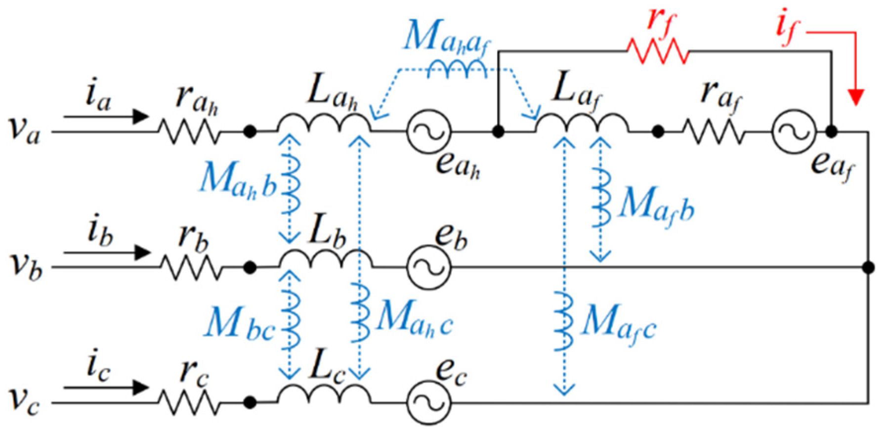
The circuit model of PMSM with ITSC, shown in Figure 2, has been widely used to study the effects of ITSC.
Each phase is modeled using its resistance (rs), self and mutual inductance (L and M) and the back-EMFs (eabc). The ITSC is introduced by shorting a portion of healthy windings with a resistor (rf), which represents the insulation degradation between two shorted turns. Phase A is split into two separate windings, denoted as ah for the healthy part and af for the shorted area. A circulating current, if, is generated in the short-circuit path. The voltage equations for a PMSM with ITSC is given as [2]:
( v a v b v c 0 ) = ( r s 0 0 r a f 0 r s 0 0 0 0 r s 0 r a f 0 0 r a f + r f ) ( i a i b i c i f ) + ( L a M a b M a c L f M b a L b M b c M b a f M c a M c b L c M c a f L f M a f b M a f c L a f ) d d t ( i a i b i c i f ) + ( e a e b e c e a f )
where
e a e b e c e a f = ω e λ p m cos θ e ω e λ p m cos θ e 2 π / 3 ω e λ p m cos θ e + 2 π / 3 Δ ω e λ p m cos θ e
in which the following are defined: vabc is the phase voltage; iabc is the phase current; raf is the resistance of the shorted turns; Labc is the three-phase self-inductance; Mab, Mac and Mbc are the mutual inductances between phase A-B, phase B-C and phase A-C, respectively; Laf is the self-inductance of the shorted turns; Mafb and Mafc are the mutual inductances between the shorted turns and phase B and phase C, respectively; Mahaf is the mutual inductance between the healthy turns of phase A and shorted turns; eaf is the back-EMF of the shorted turns; λpm is the flux linkage of the permanent magnet; ωe is the electrical angular velocity; θe is the electrical angular. The number of turns involved in the ITSC is denoted as Nf and the total number of turns per phase is Ntotal. The ratio is defined as follows:
Δ = N f N t o t a l
The values of the resistance and inductance corresponding to the fault, used in (15), are determined by the parameters of the healthy machine and the Δ, as shown in (17).
r a f = Δ r s L a f = Δ 2 L a M a h a f = Δ 1 Δ L a M a f b = M b a f = Δ M a b M a f c = M c a f = Δ M a c L f = L a f + M a h a f
Comparing with the equations in healthy condition, a fourth line, which shows the voltage relationship with the circling circuit, is added. Additionally, the remaining healthy part (rows 1 to 3) are affected by the circulating current.

3.2. Simulation Results

A single-layer fractional-slot concentrated-winding PMSM is analyzed in this work. The main advantage of this configuration relating to decreasing the effect of winding fault is eliminating the possibility of overlapping between end windings of different phases, leading to low mutual inductance between phases, therefore reducing the effect of the short-circuit current in one phase has on others. For this winding configuration, all the mutual inductances between the healthy coil or the faulted coil in the faulty phase and the other two healthy phases can be neglected [2], while the mutual inductance between the healthy coil and the faulted coil is not negligible as they share the same slot. The healthy machine specification is described in Table 1. The self and mutual inductances regarding the ITSC are determined according to (17), in the same way as that in [2].
A simulation setup was built in Simulink based on the faulty PMSM model in (14), and the ITSC was introduced to phase A.

3.3. Fault Feature Analysis

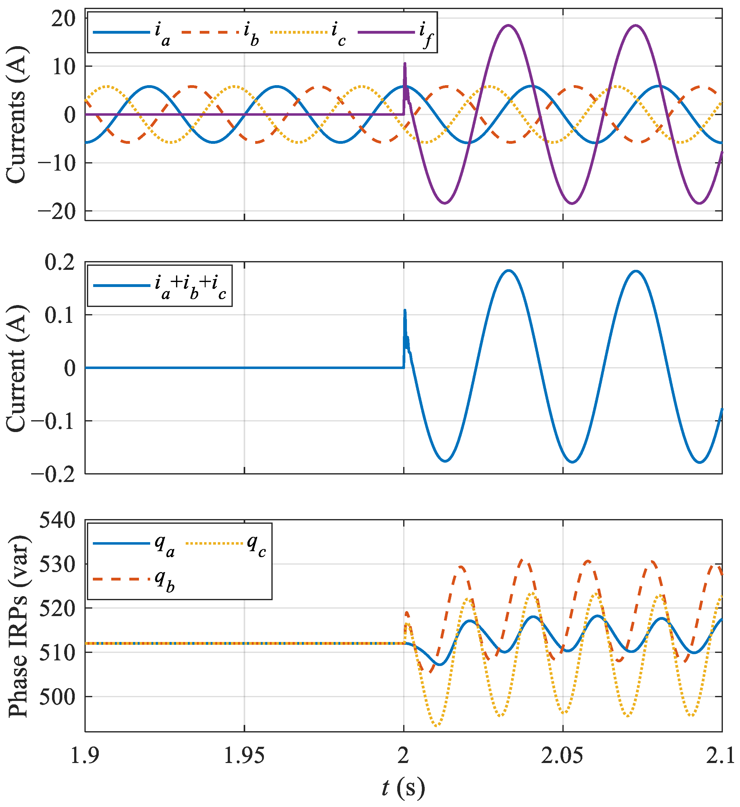
The machine was operated in constant speed mode under FOC control, id was set to zero. Figure 3 shows the phase currents and the circulating current, the neutral current and the phase IRPs before and after introducing ITSC at t = 2 s.
The ITSC generated a circulating current, if, in the short-circuit path, and a small current in the same phase of if was introduced to the neutral conductor due to the fault. It was clear that the ITSC also caused dc component changes and the second harmonic pulsations in the three-phase IRPs. Moreover, the second harmonic amplitude of qa was smaller than that of qb and qc, which was reasonable because more disturbance was generated in the faulty phase (phase A) compared to the other two healthy phases. According to (3), the pulsations in qb and qc should be larger than that in qa.
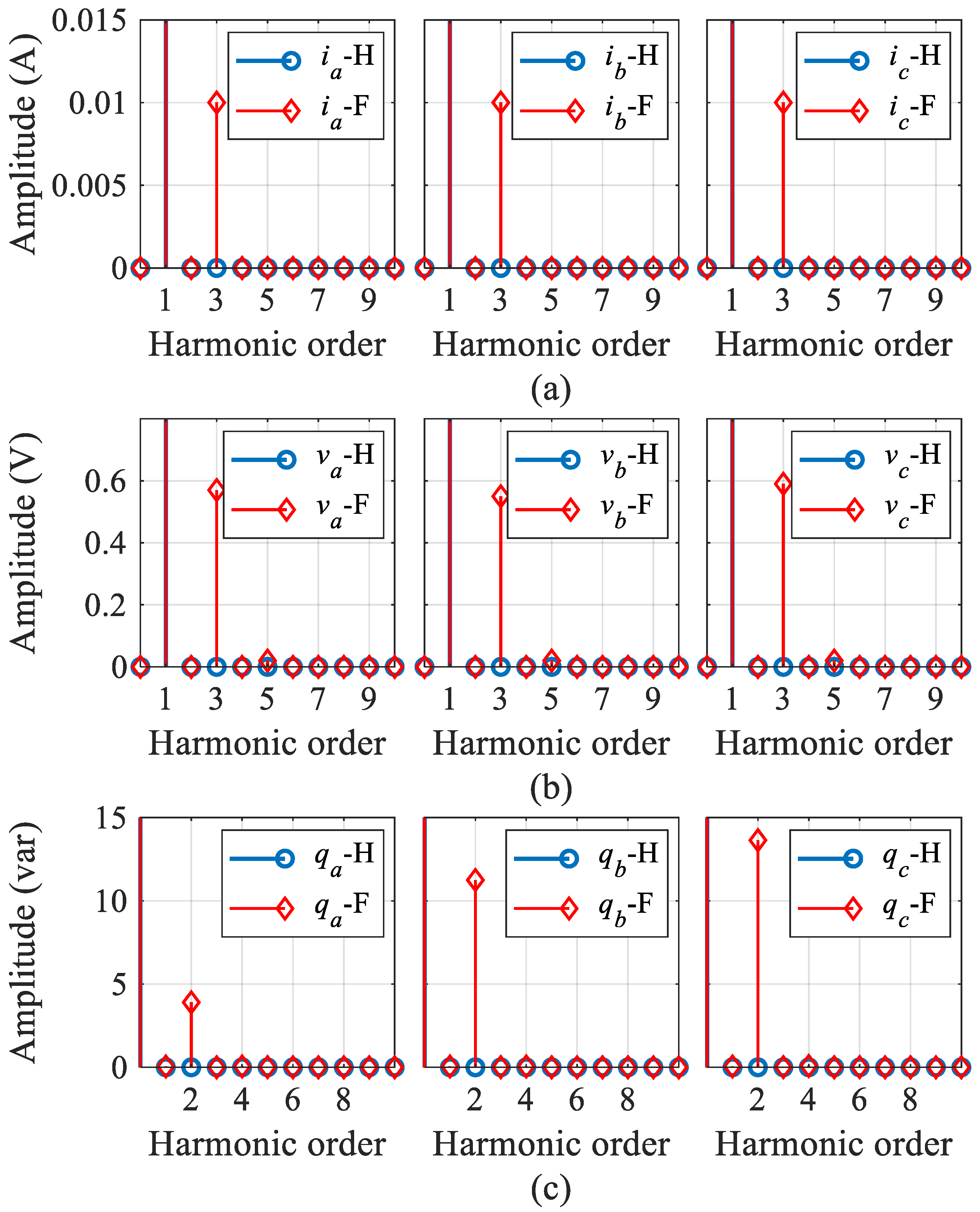
Figure 4 shows the spectra of currents, voltages and phase IRPs in healthy and faulty cases marked with H and F, respectively. According to (3), IRPs contain more fault information than voltages and currents. The fundamentals of currents and voltages in Figure 4a,b and the dc components of phase IRPs in Figure 4c are relatively high and do not change much after ITSC, and hence they are not shown in Figure 4.
Apparently, the third harmonics in currents and voltages, and the second harmonics in phase IRPs increase after ITSC. In order to eliminate the effects of units and make it comparable, the percentages of third harmonic current and voltage to their fundamentals, and the percentage of second harmonic IRP to its dc component, which is the proposed indicator, are presented in Table 2.
The third harmonics in currents and voltages, and the second harmonics in phase IRPs are zero in healthy case. Hence, the ITSCs can be detected by the spectra analysis of currents, voltages or IRPs. However, from Table 2, it is clear that the percentages of the second harmonic phase IRPs are larger than that of the third harmonics in currents and voltages, which means the fault can be detected more reliably using the proposed indicator. According to (12), the reason for the high second harmonic of IRP is that it contains not only the third harmonics in the voltages and currents (Vx3, Ix3, x = a, b, c), but also the unbalances of the fundamental components (Vx, x = a, b, c) caused by ITSC. Moreover, the indicators of qb and qc are greater than qa, which provides a method to locate the faulty phase.

3.4. ITSCs Detection at Different Operating Conditions

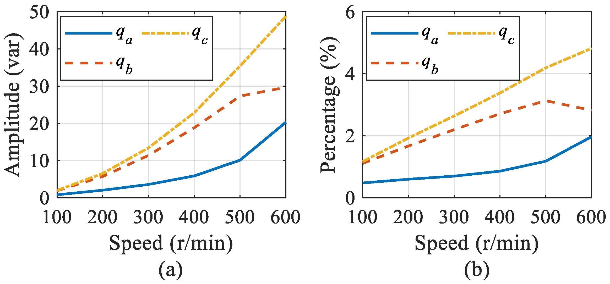
The effectiveness of the proposed indicator was validated under different operating conditions. The amplitudes of the second harmonic IRPs and the proposed indicators, at different speeds, are shown in Figure 5, where the fault severity is the same as that in Figure 3.
Both the amplitudes and the percentages increase as the speed increases, which is mainly caused by the increasing voltages due to the EMFs. As introduced in the previous section, the qa indicator is always below that of qb and qc, which makes it available for ITSC location. In Figure 5a, the amplitude of qa also behaves similarly, always below that of qb and qc. However, the difference at low speeds is not obvious.
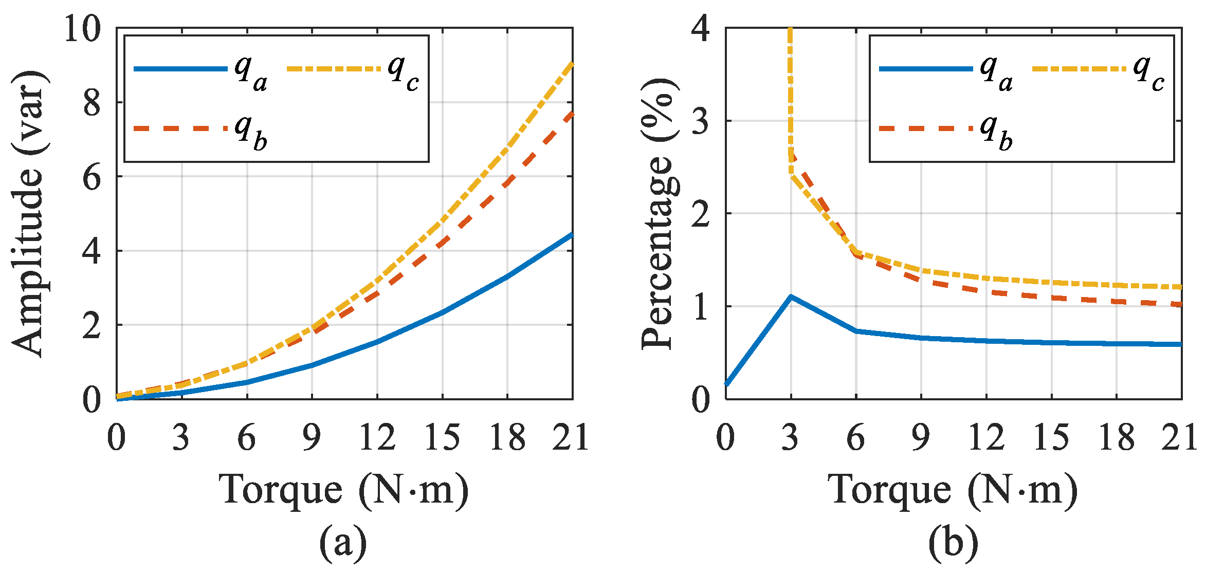
The machine was also tested at different load torques with the same fault severity, and the results are shown in Figure 6. At zero torque, there was no current injected into the machine, and the amplitudes of the second harmonic IRPs are close to zero, as shown in Figure 6a. Despite this, the circulating current due to the EMFs of the shorted turns introduces more features to the faulty phase than the other two healthy phases. In the case of zero torque, the percentages of qb and qc are 79.9% and 105.3%, respectively, which are very high and caused by the small dc components of qb and qc.
The results from Figure 6b also confirm that the ITSC in phase A can be located because the qa indicator is always below that of qb and qc at the whole torque range.
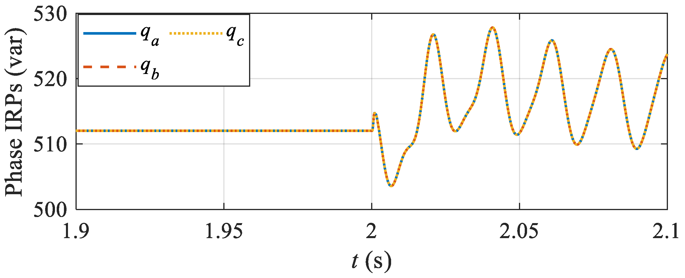
Above, the proposed ITSCs indicator is valid for a three-phase PMSM with a neutral conductor. If the neutral is not connected, the fault still can be detected by this indicator; however, the faulty phase location is not available. Because the three-phase currents add up to zero, the phase IRPs will have the same dc component changes and the same harmonic fluctuations, according to (3). In this case, the phase IRPs are shown in Figure 7.

4. Experimental Validation

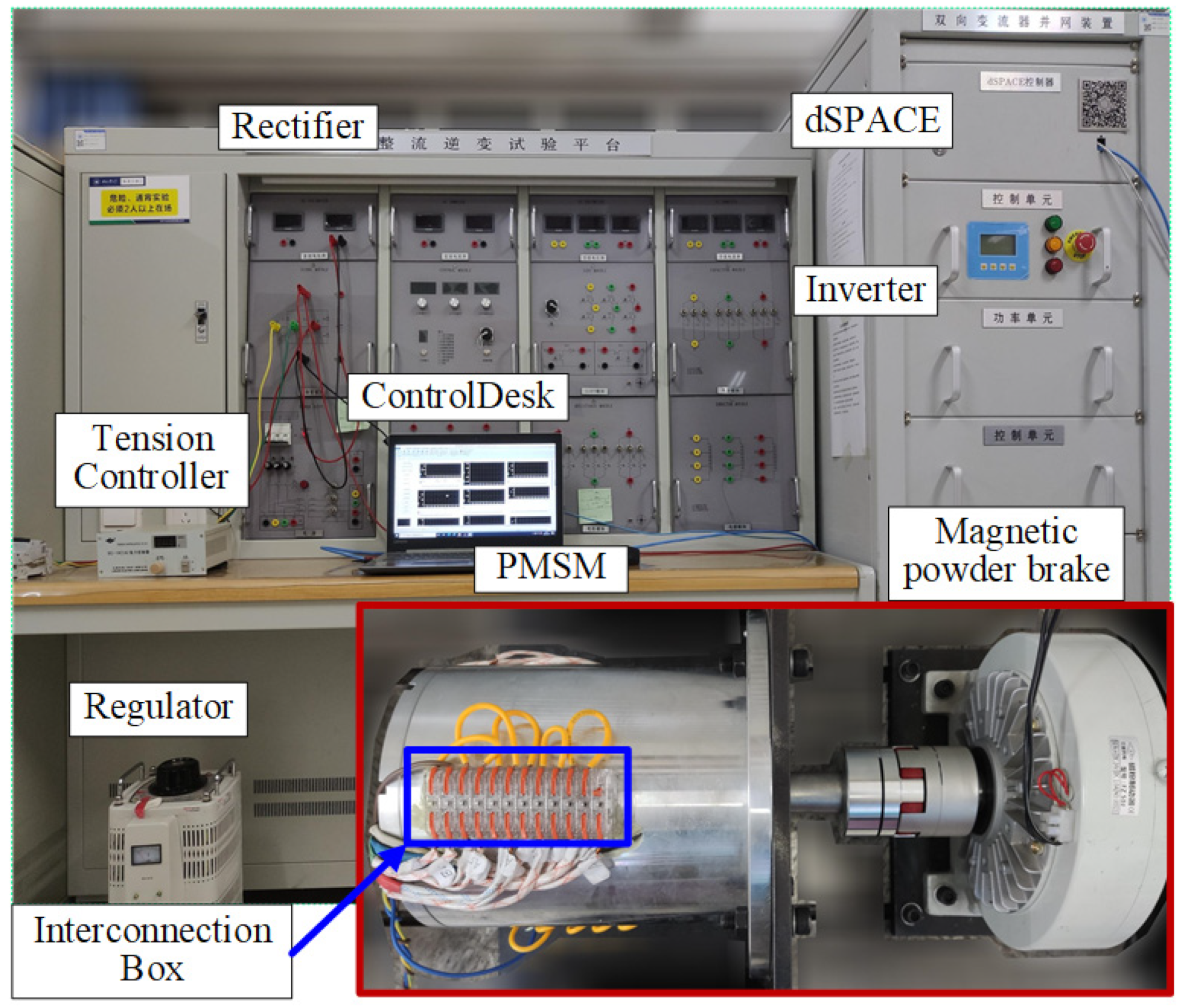
To verify the proposed indicator for ITSC detection in this work, an experimental setup was established as shown in Figure 8. The load was lifted by the magnetic powder brake controlled by the tension controller. The voltages and currents are obtained by the Hall sensors and sent to the dSPACE through bus data communication. Finally, data processing and waveform are carried out through the ControlDesk.
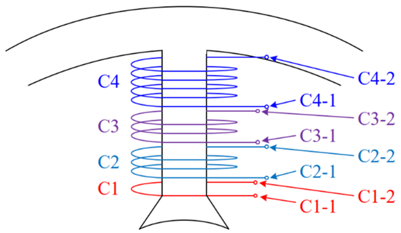
The tested faulty prototype is a surface-mounted PMSM without neutral conductor, and its design parameters are shown in Table 1. Each phase winding of the prototype is composed of two coil sets connected in parallel. In order to introduce ITSC fault in experiments, one of the coil sets of phase A is redesigned as shown in Figure 9, where the coil is wound by four sub-coils with different turns. The two ends of each sub-coil are drawn out and connected to an interconnection box. These sub-coils are shorted in series to form a winding in healthy state. Then, ITSCs with different numbers of short-circuit turns and different degrees of insulation degradation can be obtained by connecting different sub-coils in parallel with variable resistors.

4.1. Fault Feature Analysis in Experiments

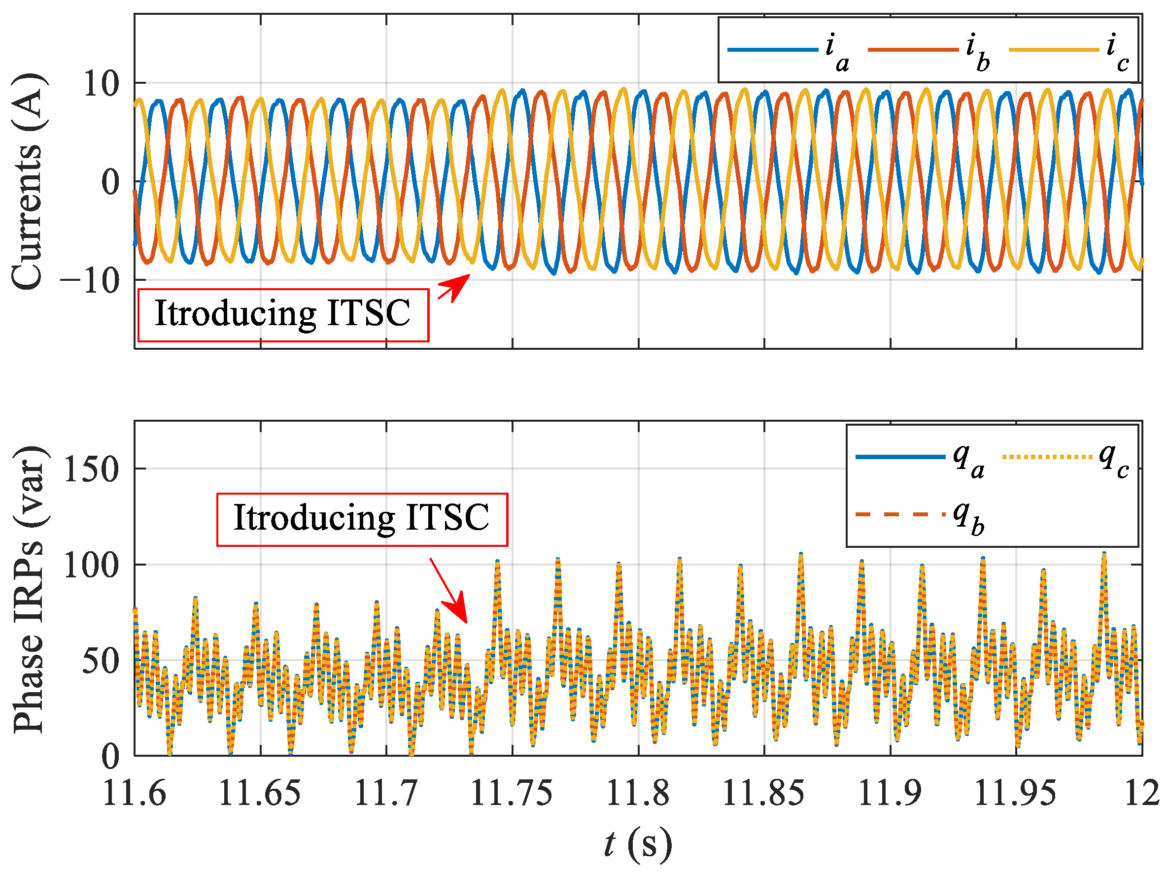
The machine was operated in constant speed mode under FOC control, id was set to zero. Figure 10 shows the phase currents, and phase IRPs before and after introducing ITSC at t = 11.74 s. The slight increase in phase currents can be observed after introducing ITSC, which is mainly due to the braking torque caused by the circulating current in the shorted turns, and the phase currents have to be increased to match the load torque. The braking torque due to the fault increases as the number of shorted turns and the amplitude of the circulating current increase [25]. In addition, the ITSC also caused dc component variations and more pulsations in the phase IRPs. The increased pulsations turn out to be mainly the second harmonics. It is clear that the phase IRPs contain harmonic components even in the healthy condition, which are caused by the inherent unbalances in the machine and setup. The three-phase IRPs have the same waveform because no neutral is connected.
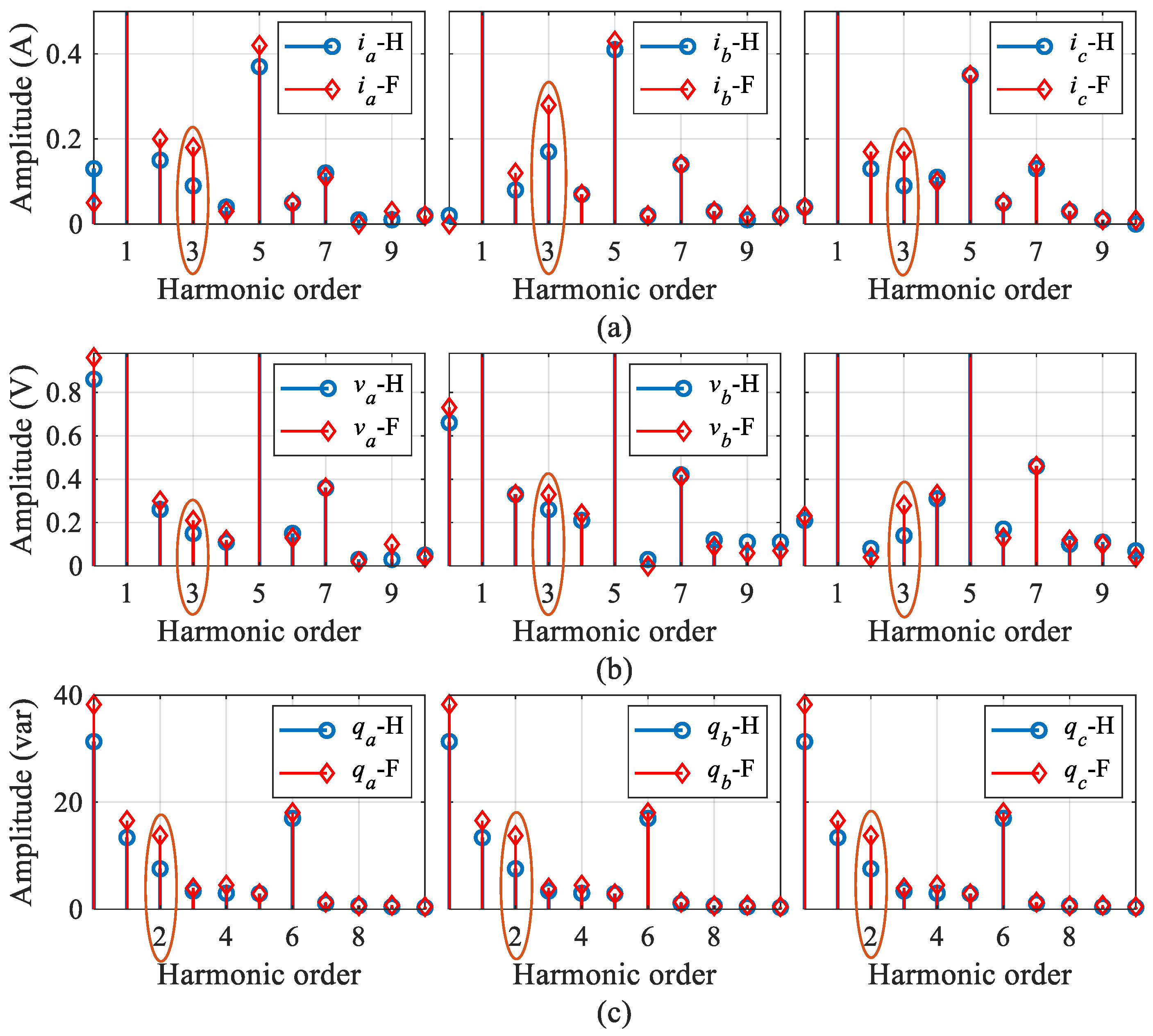
Figure 11 shows the spectra of currents, voltages and IRPs in healthy and faulty cases marked with H and F, respectively. Due to the inherent unbalance, harmonics in the phase IRPs and higher harmonics in currents and voltages (in addition to the fundamentals) can be seen in healthy condition. Under ITSC condition, compared to other harmonics, the third harmonic currents and voltages, and the second harmonic IRPs increase significantly as shown in Figure 11.
The percentages of the third harmonics to their fundamentals in currents and voltages, and the proposed indicators, are compared in Table 3. It can be obviously seen that the proposed indicators have higher percentage values than the third harmonic currents and voltages, which shows the effectiveness of the proposed indicator. The second harmonics of three-phase IRPs have the same amplitude which is reasonable for a PMSM without neutral conductor.

4.2. Performance of Proposed Indicator

The performance of the proposed indicator was evaluated under different operating conditions. The motor with Δ = 0.1 shorted turns of phase A was tested with varying motor speed (from 100 r/min to 800 r/min with a step of 100) at fixed torque (TL = 3 N∙m), and with varying load torque (from 0 to 21 N∙m with a step of 3) at fixed speed (ωm = 400 r/min). During the tests, a short-circuit resistor rf = 0.2 Ω was added to limit the circulating current if and avoid motor failure. The amplitudes of the second harmonic IRPs and the proposed indicator under different speeds and different torques are presented in Figure 12 and Figure 13, respectively, where the healthy case and faulty case are marked with H and F, respectively. Since |qa|, |qb| and |qc| are the same, only |qa| is shown in the results.
It is difficult to accurately detect ITSCs for motors running at low speed. As shown in Figure 12a, although the amplitude of second harmonic qa increased from 0.283 to 0.533 after ITSC at 100 r/min, which means the fault can be detected theoretically, the amplitude of the second harmonic qa itself is relatively small at low speed, and is not credible for fault detection due to its low signal-to-noise ratio. In this situation, the disturbance in the motor system is more likely to cause misdiagnosis. Compared with amplitude, the indicator has a better performance at low speed. The indicator increased from 38.6% to 48.6% after ITSC at 100 r/min, as shown in Figure 12b, and this high percentage value and its increase make it credible for fault detection due to the high signal-to-noise ratio. As the speed increases from 100 to 800 r/min, both the amplitude and percentage of second harmonic qa increase due to the increased circulating current caused by the higher back EMF of shorted turns at higher speed, and it can be seen that the proposed indicator is reliable for ITSC detection within the rated motor speed, as shown in Figure 12b.
Under different load torque, both the amplitude and percentage of second harmonic qa increase significantly after ITSC, as shown in Figure 13. Since the circulating current increases with the stator currents, the amplitude of second harmonic qa increases with torque, as shown in Figure 13a. However, the percentage decreases with torque, as shown in Figure 13b, because the amplitude of second harmonic qa is more sensitive to speed than to torque [17], and the dc component of qa increases significantly with torque. Similarly to the case at low speed in Figure 12a, the amplitude of second harmonic qa at zero torque is relatively small, which means the fault detection based on amplitude is not reliable enough. As a contrast, the percentage at zero torque is high due to the low dc component of qa, increasing from 71.84% to 120.97% after ITSC. When the motor is fully loaded at 21 N∙m, the percentage increased from 12.58% to 19.84% after ITSC. Within the rated torque range, the proposed indicator values both before and after ITSC are higher than 10%, which makes it reliable for ITSC detection in PMSM.
In practical applications, fault detection always requires a lookup table of ITSC indicator values under healthy condition. However, the indicator value varies with operating conditions, and it is difficult to determine a reasonable detection threshold. Therefore, the fault indicator needs not only a high signal-to-noise ratio, but also robustness to speed and torque. In this article, the robustness of the proposed indicator with respect to speed and torque is evaluated by coefficient of variation (CV):
C V = σ x μ x
where σx and μx are the standard deviation and the mean of amplitude or percentage of second harmonic qa. This means that small CV represents higher robustness.
From 100 to 800 r/min, the CVs of the amplitude and percentage of second harmonic qa after ITSC are 0.953 and 0.364, respectively. Therefore, the proposed indicator is more robust with respect to speed than the amplitude itself. When the motor is lightly loaded (below 9 N∙m), the percentage is high due to the low dc component of qa, which results in low robustness of the proposed indicator to torque. From 9 to 21 N∙m, the CVs of the amplitude and percentage after ITSC are 0.377 and 0.238, respectively. In this case, the proposed indicator is more robust to torque than the amplitude itself.
According to the above discussion, the signal-to-noise ratio, robustness to motor speed and the capability of locating ITSC were compared and presented in Table 4. It shows that the proposed method has a higher signal-to-noise ratio and is more robust to motor speed. In addition, for the motors with neutral conductors, the proposed method can locate the faulty phase when ITSC occurs.
Overall, the proposed indicator can achieve effective detection of ITSC within the rated operating range.

4.3. Online Fault Detection Algorithm

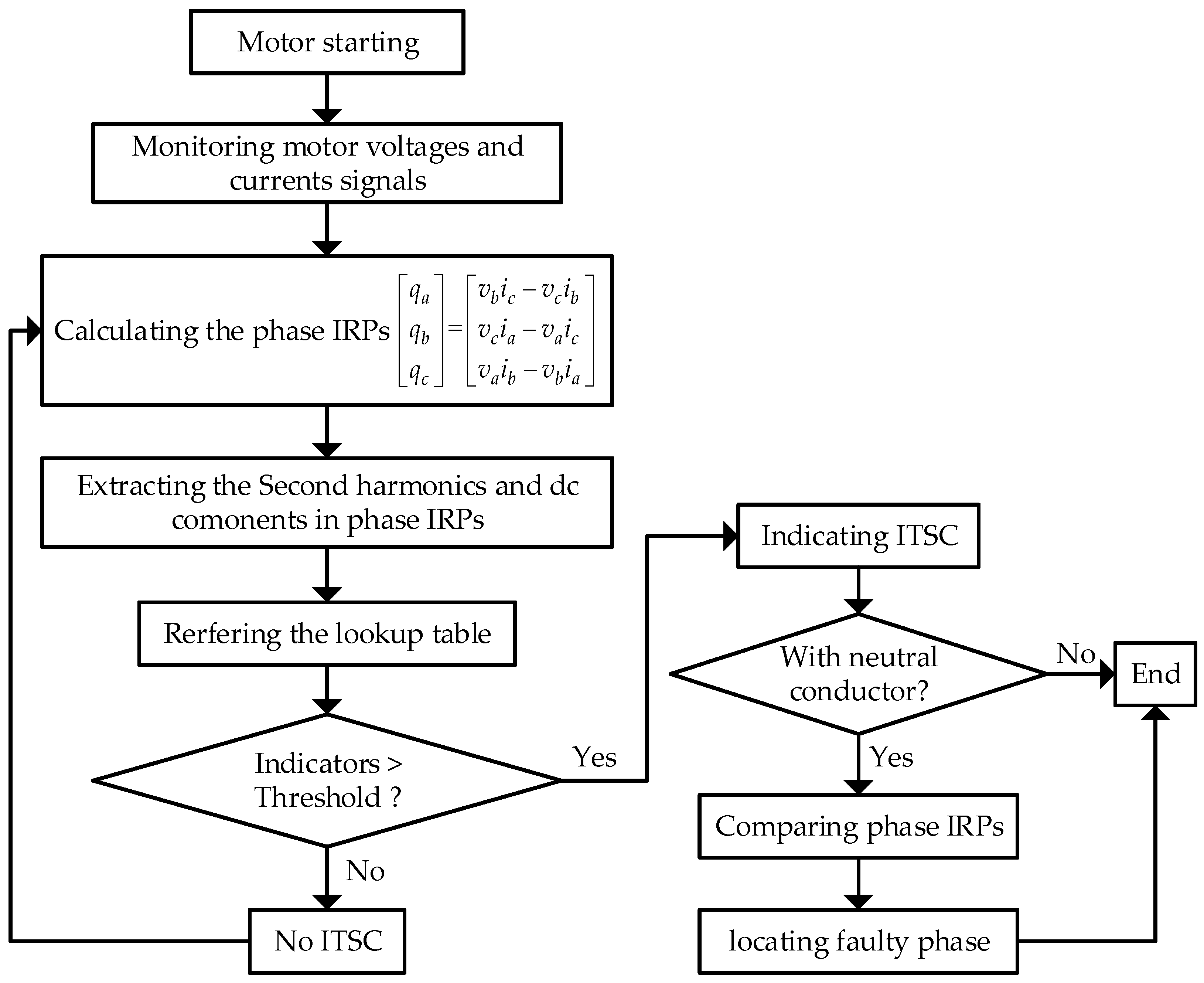
The flowchart of the algorithm of the proposed online ITSC detection is shown in Figure 14, which is synchronous with the motor drive system control frequency (10 kHz). Before introducing ITSC to the motor, a lookup table needs to be established first under different motor operating conditions to store the indicator values in healthy conditions, and a reasonable detection threshold should be determined. During the motor operating, the dc components and second harmonics in phase IRPs are extracted online by a quadrature digital lock-in amplifier, and the indicator is calculated. According to the operating condition and referring to the lookup table, if the indicator value is higher than the threshold, then an ITSC is detected. For the motor with a neutral conductor, the three phase IRPs are compared to locate the faulty phase.

5. Conclusions

ITSC introduces imbalance to PMSM and generates third harmonics in phase currents and voltages, and IRP combines the fault features in voltages and in currents and provides a more reliable ITSC detection method. The definition of phase IRPs in abc frame of reference makes it possible to not only detect ITSCs but also locate the faults for the PMSMs with neutral conductors. Simulation results show that the percentages of the second harmonics in phase IRPs to their dc components are more appropriate for the faulty phase location than the amplitudes themselves. The ITSCs detection at different operating conditions shows that the proposed indicator of faulty phase is always lower than that of the other two healthy phases, and the differences are credible for fault location. Moreover, the effectiveness of the proposed indicator in ITSCs detection is validated in experiments. The values of the proposed indicator are always higher than 10% within the rated motor operating range, and hence, its high signal-to-noise ratio is beneficial for a reliable ITSC detection. Additionally, its robustness with respect to motor operating conditions, especially the speed, is evaluated by CV. From 100 to 800 r/min, the CV of the proposed indicator is smaller than that of the amplitude of second harmonic IRP, which means the proposed indicator is more robust with respect to speed. This high robustness is beneficial for obtaining a reasonable fault detection threshold under various operating conditions.
The results in this work are from steady state, and the proposed indicator can be used to detect ITSCs in PMSMs online by introducing harmonic extraction techniques to the drive systems [17].

Author Contributions

Conceptualization, S.H.; methodology, S.H. and Z.B.; software, S.H., Z.B. and Z.S.; validation, Z.S. and Z.B.; formal analysis, S.H. and Z.B.; investigation, F.N. and S.H.; resources, Z.S. and Z.B.; data curation, Z.B. and Z.S.; writing—original draft preparation, S.H. and Z.B.; writing—review and editing, A.A. and F.N.; visualization, S.H. and Z.B.; supervision, X.H. and L.W.; project administration, F.N., X.H. and L.W. All authors have read and agreed to the published version of the manuscript.

Funding

This research was funded in part by the National Nature Science Foundation of China under Grant 52077054, in part by the China Postdoctoral Science Foundation under Grant 2021T140077 and 2020M681446, in part by the National Undergraduate Innovation and Entrepreneurship Training Program under Grant 2022J00090, in part by the Foundation for Creative Research Groups of Hebei Province under Grant E2020202142, and in part by the State Key Laboratory of Reliability and Intelligence of Electrical Equipment under Grant PI2020002, Hebei University of Technology.

Conflicts of Interest

The authors declare no conflict of interest.

References

  1. Drif, M.; Cardoso, A.J.M. Stator Fault Diagnostics in Squirrel Cage Three-Phase Induction Motor Drives Using the Instantaneous Active and Reactive Power Signature Analyses. IEEE Trans. Ind. Inform. 2014, 10, 1348–1360. [Google Scholar] [CrossRef]
  2. Foster, S.N.; Cintron-Rivera, J.G.; Strangas, E.G. Detection of incipient stator winding faults in PMSMs with single-layer fractional slot concentrated windings. Electr. Power Syst. Res. 2016, 131, 231–243. [Google Scholar] [CrossRef]
  3. Ebrahimi, B.M.; Faiz, J. Feature Extraction for Short-Circuit Fault Detection in Permanent-Magnet Synchronous Motors Using Stator-Current Monitoring. IEEE Trans. Power Electron. 2010, 25, 2673–2682. [Google Scholar] [CrossRef]
  4. Faiz, J.; Exiri, A.H.; Nejadi-Koti, H. Current-based inter-turn short circuit fault modeling in permanent magnet synchronous machine using magnetic equivalent circuit model. In Proceedings of the 10th International Conference on Compatibility, Power Electronics and Power Engineering (CPE-POWERENG), Bydgoszcz, Poland, 1–29 June 2016. [Google Scholar]
  5. Saavedra, H.; Saavedra, J.-C.; Riba, U.J.-R.; Rome-ral, L. Detection of interturn faults in PMSMs with different winding configurations. Energy Convers. 2014, 79, 534–542. [Google Scholar] [CrossRef]
  6. Hang, J.; Zhang, J.; Cheng, M. Online Interturn Fault Diagnosis of Permanent Magnet Synchronous Machine Using Zero-Sequence Components. IEEE Trans. Power Electron. 2015, 30, 6731–6741. [Google Scholar] [CrossRef]
  7. Boileau, T.; Leboeuf, N.; Nahid-Mobarakeh, B.; Meibody-Tabar, F. Synchronous demodulation of control voltages for stator interturn fault detection in PMSM. IEEE Trans. Power Electron. 2013, 28, 5647–5654. [Google Scholar] [CrossRef]
  8. Ahn, G.; Lee, J.; Park, C.H.; Youn, M.; Youn, B.D. Inter-turn short circuit fault detection in permanent magnet synchronous motors based on reference voltage. In Proceedings of the IEEE 12th International Symposium on Diagnostics for Electrical Machines, Power Electronics and Drives (SDEMPED), Toulouse, France, 27–30 August 2019. [Google Scholar]
  9. Moon, S.; Jeong, H.; Lee, H.; Kim, S.W. Detection and classification of demagnetization and interturn short faults of IPMSMs. IEEE Trans. Ind. Electron. 2017, 64, 9433–9441. [Google Scholar] [CrossRef]
  10. Qi, Z.; Liang, Y. Evaluating the stator winding inter-tern short circuit fault of permanent magnet motor using FEA combined with experiment. In Proceedings of the 2014 17th International Conference on Electrical Machines and Systems (ICEMS), Hangzhou, China, 22–25 October 2014. [Google Scholar]
  11. Sarikhani, A.; Mohammed, O.A. Inter-Turn Fault Detection in PM Synchronous Machines by Physics-Based Back Electromotive Force Estimation. IEEE Trans. Ind. Electron. 2013, 60, 3472–3484. [Google Scholar] [CrossRef]
  12. Haddad, R.Z.; Strangas, E.G. On the accuracy of fault detection and separation in permanent magnet synchronous machines using MCSA/MVSA and LDA. IEEE Trans. Energy Convers. 2016, 31, 924–934. [Google Scholar] [CrossRef]
  13. Moon, S.; Jeong, H.; Lee, H.; Kim, S.W. Interturn short fault diagnosis in a PMSM by voltage and current residual analysis with the faulty winding model. IEEE Trans. Energy Convers. 2018, 33, 190–198. [Google Scholar] [CrossRef]
  14. Çira, F.; Arkan, M.; Gümüş, B.; Goktas, T. Analysis of stator inter-turn short-circuit fault signatures for inverter-fed permanent magnet synchronous motors. In Proceedings of the IECON 42nd Annual Conference of the IEEE Industrial Electronics Society, Florence, Italy, 23–26 October 2016. [Google Scholar]
  15. Du, B.; Wu, S.; Han, S.; Cui, S. Interturn fault diagnosis strategy for interior permanent magnet synchronous motor of electric vehicles based on digital signal processor. IEEE Trans. Ind. Electron. 2016, 63, 1694–1706. [Google Scholar] [CrossRef]
  16. Qi, Y.; Zafarani, M.; Akin, B. A diagnosis procedure in standstill mode for inter turn short circuit faults of PMSMs through modified self-commissioning. In Proceedings of the 2016 IEEE Energy Conversion Congress and Exposition (ECCE), Milwaukee, WI, USA, 18–22 September 2016. [Google Scholar]
  17. Huang, S.; Aggarwal, A.; Strangas, E.G.; Li, K.; Niu, F.; Huang, X. Robust Stator Winding Fault Detection in PMSMs With Respect to Current Controller Bandwidth. IEEE Trans. Power Electron. 2021, 36, 5032–5042. [Google Scholar] [CrossRef]
  18. Urresty, J.; Riba, J.; Romeral, L. Diagnosis of Interturn Faults in Pmsms Operating under Nonstationary Conditions by Applying Order Tracking Filtering. IEEE Trans. Power Electron. 2013, 28, 507–515. [Google Scholar] [CrossRef]
  19. Wang, B.; Wang, J.; Griffo, A.; Sen, B. Stator turn fault detection by second harmonic in instantaneous power for a triple-redundant fault-tolerant PM drive. IEEE Trans. Ind. Electron. 2018, 65, 7279–7289. [Google Scholar] [CrossRef] [Green Version]
  20. Eltabach, M.; Charara, A.; Zein, I. A comparison of external and internal methods of signal spectral analysis for broken rotor bars detection in induction motors. IEEE Trans. Ind. Electron. 2004, 51, 107–121. [Google Scholar] [CrossRef]
  21. Abadi, M.B. Detection of stator and rotor faults in a DFIG based on the stator reactive power analysis. In Proceedings of the IECON 40th Annual Conference of the IEEE Industrial Electronics Society, Dallas, TX, USA, 29 October–1 November 2014. [Google Scholar]
  22. Huang, S.; Strangas, G.; Li, K.; Niu, F. Detection of inter-turn short-circuit faults in PMSMs based on instantaneous reactive power. In Proceedings of the 7th International Conference on Reliability of Electrical Products and Electrical Contacts, Suzhou, China, 4–6 November 2019. [Google Scholar]
  23. Drif, M.; Cardoso, A.J.M. The use of the instantaneous-reactive-power signature analysis for rotor-cage-fault diagnostics in three-phase induction motors. IEEE Trans. Ind. Electron. 2009, 56, 4606–4614. [Google Scholar] [CrossRef]
  24. Jeong, I.; Hyon, B.J.; Nam, K. Dynamic Modeling and Control for SPMSMs With Internal Turn Short Fault. IEEE Trans. Power Electron. 2013, 28, 3495–3508. [Google Scholar] [CrossRef]
  25. Lee, Y.; Habetler, T.G. A phase variable simulation model for interior PM synchronous motor drives with stator turn faults. In Proceedings of the 12th International Power Electronics and Motion Control Conference, Portoroz, Slovenia, 30 August–1 September 2006. [Google Scholar]
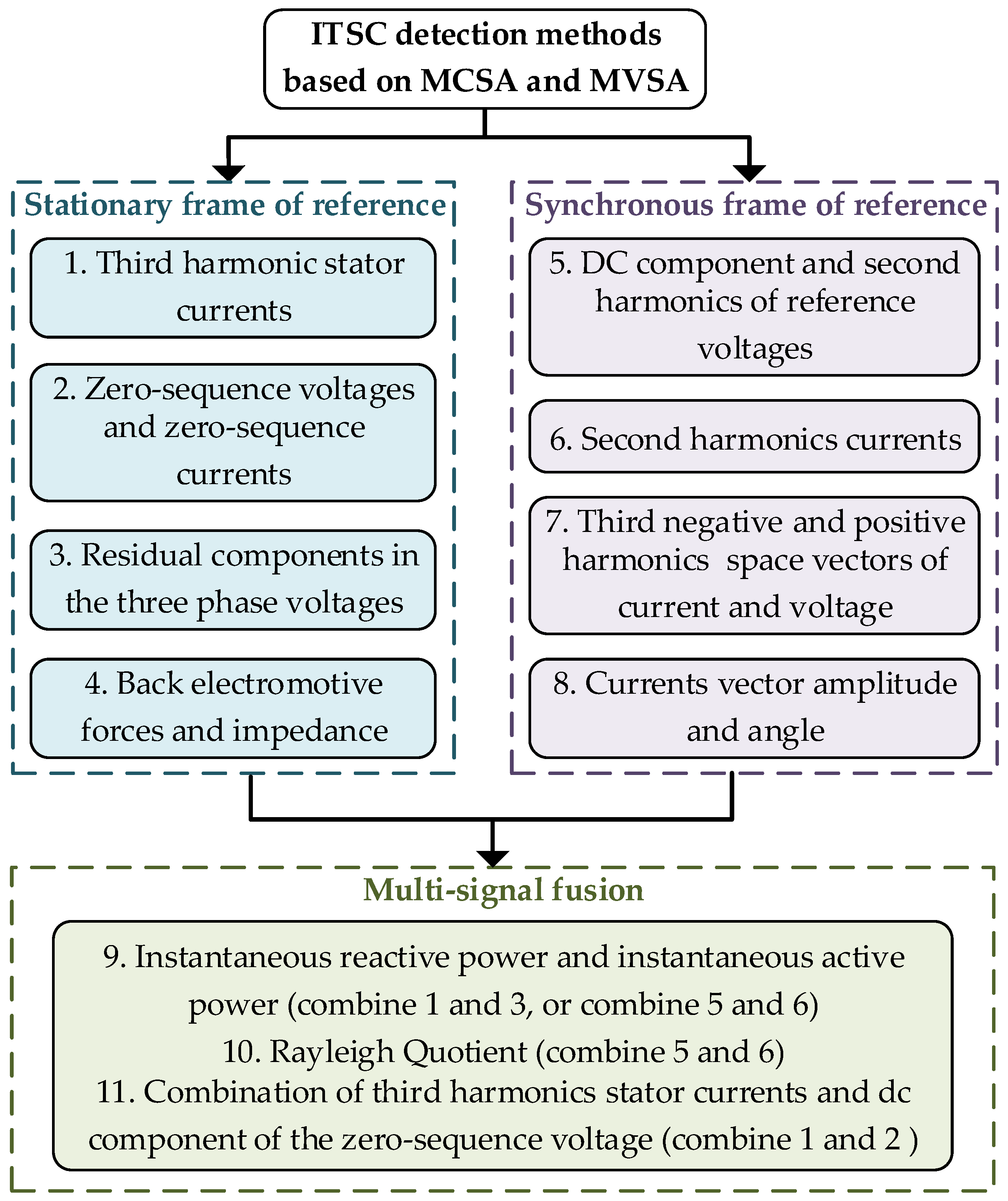
Figure 1. Classification and connection of detection methods.
Energies 15 03248 g001
Figure 2. Three-phase electrical model for a PMSM with ITSC.
Energies 15 03248 g002
Figure 3. The phase currents and circulating current (top), the neutral current (middle) and the phase IRPs (bottom) before and after ITSC. Operating conditions: machine speed ωm = 300 r/min and load torque TL = 10 N∙m. Fault severity: Δ = 0.01, rf = 50 mΩ.
Energies 15 03248 g003
Figure 4. The spectra of currents (a), voltages (b) and phase IRPs (c) in healthy and faulty cases. The same operating conditions and fault severity as that in Figure 3.
Energies 15 03248 g004
Figure 5. The amplitudes of the second harmonics in IRPs (a) and the proposed indicators (b), with ITSC, at different speeds. TL was fixed at 10 N∙m.
Energies 15 03248 g005
Figure 6. The amplitudes of the second harmonics in IRPs (a) and the proposed indicators (b), with ITSC, at different torques. ωm was fixed at 100 r/min.
Energies 15 03248 g006
Figure 7. The phase IRPs before and after ITSC, without neutral conductor. Operating conditions: machine speed ωm = 300 r/min and load torque TL = 10 N∙m. Fault severity: Δ = 0.01, rf = 50 mΩ.
Energies 15 03248 g007
Figure 8. Experimental setup for ITSCs detection.
Energies 15 03248 g008
Figure 9. Stator winding configuration of phase A.
Energies 15 03248 g009
Figure 10. The phase currents and circulating current (top), the neutral current (middle) and the phase IRPs (bottom) before and after ITSC. Operating conditions: machine speed ωm = 500 r/min and load torque TL = 10 N∙m. Fault severity: Δ = 0. 1, rf = 0.2 Ω.
Energies 15 03248 g010
Figure 11. The spectra of currents (a), voltages (b) and phase IRPs (c) in healthy and faulty cases. The same operating conditions and fault severity as Figure 10.
Energies 15 03248 g011
Figure 12. The amplitudes of the second harmonics in IRPs (a) and the proposed indicators (b), with ITSC, at different speeds. TL was fixed at 3 N∙m.
Energies 15 03248 g012
Figure 13. The amplitudes of the second harmonics in IRPs (a) and the proposed indicators (b), with ITSC, at different torques. ωm was fixed at 400 r/min.
Energies 15 03248 g013
Figure 14. The flowchart of the online detection algorithm.
Energies 15 03248 g014
Table 1. Machine Specification.
ParameterValueParameterValue
Number of phases3Number of Slots/Poles12/10
Rated phase current Irms18 ATurns of Phase Ntotal300
Rated line voltage Vrms480 VPhase Resistance rs1.5 Ω
Base speed800 r/minPhase Inductance Ls112 mH
Magnet flux λpm0.23 WbMutual Inductance Ms≈0 mH
Table 2. Percentages of Fault Feature (%).
Currents 3 r d 1 s t × 100 Voltages 3 r d 1 s t × 100 IRPs 2 r d d c × 100
ia0.19va0.5qa0.76
ib0.18vb0.51qb2.17
ic0.18vc0.53qc2.68
Table 3. Percentages of Fault Feature (%).
Currents 3 r d 1 s t × 100 Voltages 3 r d 1 s t × 100 IRPs 2 r d d c × 100
ia1.92va0.48qa35.96
ib3.04vb0.73qb35.96
ic1.88vc0.61qc35.96
Table 4. Comparison of Advantages and Disadvantages of ITSC Detection Methods.
Detection MethodsSignal-to-Noise RatioRobustness to SpeedCapability of Fault Location
Method based on the third harmonic stator voltagesLowLow
Method based on the third harmonic stator currentsLowLow
Method based on the second harmonic IRPsMediumLow×
The proposed methodsHighHigh
Publisher’s Note: MDPI stays neutral with regard to jurisdictional claims in published maps and institutional affiliations.