Abstract
Concerns about climate change, air pollution, and the depletion of oil resources have prompted authorities to enforce increasingly strict rules in the automotive sector. There are several benefits to implementing fuel cell hybrid vehicles (FCHV) in the transportation sector, including the ability to assist in reducing greenhouse gas emissions by replacing fossil fuels with hydrogen as energy carriers. This paper examines different control strategies for optimizing the power split between the battery and PEM fuel cell in order to maximize the PEM fuel cell system efficiency and reduce fuel consumption. First, the vehicle and fuel cell system models are described. A forward approach is considered to model the vehicle dynamics, while a semi-empirical and quasi-static model is used for the PEM fuel cell. Then, different rule-based control strategies are analyzed with the aim of maximizing fuel cell system efficiency while ensuring a constant battery state of charge (SOC). The different methods are evaluated while the FCHV is performing both low-load and high-load drive cycles. The hydrogen consumption and the overall fuel cell system efficiency are considered for all testing conditions. The results highlight that in both low-load cycles and high-load cycles, the best control strategies achieve a fuel cell system efficiency equal or greater to 33%, while achieving a fuel consumption 30% less with respect to the baseline control strategy in low-load drive cycles.
1. Introduction
Scientists and politicians have been becoming increasingly concerned about the effects of climate change in recent years. The transportation industry, which now depends nearly entirely on fossil fuels, is being asked to implement a decarbonization program [1]. This approach has resulted in the introduction of incentives in the automobile industry to focus on breakthrough alternative powertrain technology [2]. In this framework, there are several benefits to implementing fuel cell vehicles (FCV) in the transportation sector, including the ability to assist reduce greenhouse gas emissions by replacing fossil fuels with hydrogen as energy carriers. The advantages of FCVs are apparent, especially when hydrogen is product by renewable sources. Since they are propelled by the electrochemical reaction of hydrogen, they enable a carbon-free propulsion, and their unique by-product is pure water. As a result, fuel cells have three times the efficiency of an internal combustion engine (ICE), since they are not constrained by the Carnot cycle. Furthermore, the FCV beats electric vehicles (EV) in terms of driving range and charging time [3,4]. However, the fuel cells can have lower power density and slower power response when compared to ICE [5,6].
Due to the slow transient reaction of the fuel cells, which must be considered to prevent premature deterioration, FCVs often integrate extra electrical energy storage. Additionally, this energy storage system makes it possible to recover energy from braking. Most of the time, the energy storage system is either a battery or a supercapacitor, but there are many different ways to put the power sources together. According to [7,8], the possible configurations of a FCV powertrain are: (1) without electrical energy storage (FCV), (2) with supercapacitors directly connected to the fuel cell (Fuel Cell Electric Vehicle—FCEV) and, (3) with energy storage unit coupled in parallel with the fuel cell through a DC/DC converter (Fuel Cell Hybrid Vehicle—FCHV). Fuel cell vehicles have a basic construction and do not add much weight to the vehicle, but because of the delayed power response of the fuel cell, they need a higher power fuel cell stack and quick hydrogen/air delivery systems in order to satisfy the power requirements. Since supercapacitors have a more significant power density with respect to battery, FCVs with supercapacitors are more efficient in absorbing the regenerative braking energy and providing power in transients [9]. However, the most popular powertrain configuration among carmakers is with an energy storage unit coupled in parallel with the fuel cell through a DC/DC converter [10]. The energy storage unit is coupled in parallel with the fuel cell and provides the transient power, thus being regulated by the DC/DC converter. This arrangement shortens the start-up time and makes it possible to recover the regenerative energy. Applications can be found in the Honda FCX Clarity and the Toyota Mirai [11].
Despite the advantages of FCHVs, more research is required to manage the flow and exchange of energy among energy storage systems. To maintain the vehicle’s equivalent hydrogen consumption and efficiency during a trip, proper control of the power and energy variables is required. Moreover, the additional energy storage system should operate at the optimum operating range, and therefore, an energy management system must be designed for it and for minimizing the overall fuel consumption. Generally, there are two major types of energy management system, namely model-based and rule-based, respectively [12,13,14]. The first category aims to determine the optimal control policy by performing optimization over a predefined driving cycle, and can be further divided into offline and online optimization. The offline methods include numerical techniques such as genetic algorithms [15] and dynamic programming [16,17,18,19,20], as well as analytical techniques such as Pontryagin’s Minimum Principle [21,22]. Instead, when implementing online optimization techniques in FCHVs, the systems can be controlled through the Equivalent Consumption Minimization Strategy (ECMS) [23,24,25,26] and Model Predictive Control [27,28,29,30]. Although offline techniques are well-suited for defining the reference ideal solution, they cannot be applied in real time on a vehicle since they need previous information of the whole driving cycle.
On the other hand, the online approaches are based on the real-time optimization of a preset cost function. They can be performed online, but need precise adjustment of the reference model and may incur high computational costs. The second category of techniques, referred to as rule-based methods, makes use of deterministic [31,32,33,34,35] or fuzzy logic [26,36,37,38,39], and constitute the most well-known way of achieving real-time management in FCHV applications [40]. They are not model-based, and determine the operating point of the power source by means of rule tables to meet the requirements of other devices (e.g., battery or fuel cell) and the driver. The rules are defined on the basis of the designer’s experience and knowledge, and the resulting energy management strategy can be executed in real controllers.
Among all the possible energy management systems used in the literature for energy and power split in FCHVs, three rule-based control strategies are analyzed in this work. Indeed, a systematic approach for assessing the performance of rule-based energy management for FCHVs in terms of fuel cell system efficiency and fuel consumption minimization is not fully addressed in the mentioned literature. This consideration inspired this work, which aims to define how much the fuel cell system efficiency can be improved and how much hydrogen can be saved by using a rule-based energy management to control the power and energy split between the fuel cell and battery. The paper presents three rule-based control strategies, namely, constant power, baseline mode-based, and fuzzy logic control-based. The performance and the adjustments of the strategies are evaluated in terms of fuel cell system efficiency and fuel consumption. The first (efficiency) is computed considering all the auxiliaries of the fuel cell systems, while the second one considers the hydrogen consumption corrected according to the requirements in ISO 23274 standard [41]. The performance of the strategies is evaluated by simulation in five different driving cycles. These include three low-load driving cycles (e.g., Urban Dynamometer Driving Schedule—UDDS; New European Driving Cycle—NEDC; Federal Test Procedure—FTP) and two high-load driving cycles (e.g., Worldwide harmonized Light-Duty vehicles Test Procedure—WLTP; and Supplemental Federal Test Procedure—US06). The fuel cell system efficiency is taken into account through a semi-empirical model that also considers different auxiliary systems such as: cooling pump and fan, water recirculation pump, recirculation hydrogen blower, and compressor at cathode inlet.
In summary, the novel contribution of this work is the analysis of three different control strategies, namely, constant power, baseline mode-based, and fuzzy logic control-based. The control strategies are compared at the simulation level considering a FCHV model including a semi-empirical model for the fuel cell system. The performance and the adjustments of the strategies are evaluated in terms of fuel cell system efficiency and fuel consumption considering five different drive cycles.
The structure of the paper is as follows. Section 2 illustrates the adopted vehicle and fuel cell system modeling approach. This section also presents three different control strategies for energy management of the retained vehicle. Section 3 presents and discusses the obtained results on five different driving cycles, both low-load and high-load driving cycles. A performance analysis in terms of fuel cell system efficiency and fuel consumption is then presented. Finally, Section 4 discusses the paper’s findings.
2. Methodology
This section describes the powertrain, the fuel cell system and battery models adopted for the simulations. The design of the three proposed energy management strategies is also presented in this section.
2.1. Powertrain Model
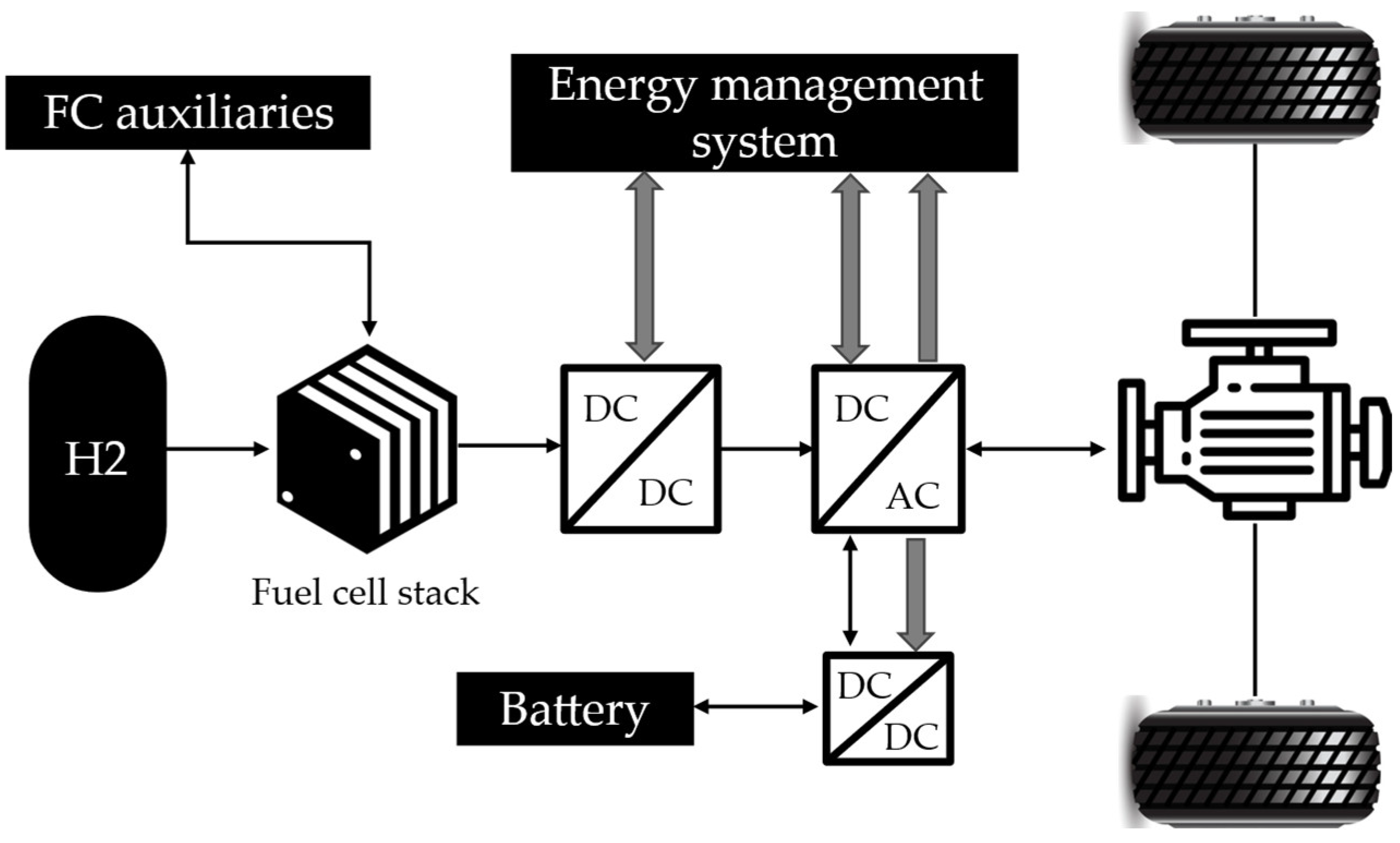
The architecture of the vehicle used in this work is reported in Figure 1.
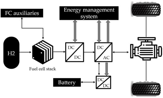
Figure 1.
FCHV powertrain architecture.
Table 1 summarizes the main parameters of the FCHV vehicle.

Table 1.
Main FCHV parameters.
According to the configuration shown in Figure 1, the electric motor supplies power to the wheels through the differential. Additionally, the electric motor may function as a generator, recovering energy during braking. The car has three manual-shifting gears, and regenerative braking is available exclusively in the lowest gear. The electric motor is linked to the direct current bus (DC-BUS) through an electronic converter. The fuel cell is the primary energy source for the FCHV and supplies power to the DC-BUS through the boost converter. Instead, the battery stores the energy recovered during braking and makes up for the instantaneous power demand when the fuel cell power is insufficient.
In this work, the vehicle dynamic model considers the power dissipated in the rolling resistance of the tires, the power due to the aerodynamic drag (), the power needed for overcoming the road grade and the power () to accelerate the vehicle equivalent inertia . Thus, Equation (1) details the requested electrical power:
Then, the demand torque at the motor is:
where is the wheel radius, is the gearbox ratio, and is the transmission efficiency. The demanded torque is corrected to respect the motor characteristic curve. Specifically, below the base speed the motor can provide up to the peak torque. Instead, at speeds greater than the motor’s base speed, the torque is limited by flux weakening, in this case the motor characteristic is well approximated by its maximum power. Furthermore, the motor speed is limited by its maximum speed, imposed, among the others, by the rotor mechanical strength.
To ensure that the power delivered by the fuel cell system and the battery satisfies the driving cycle power demand, in the present work, the battery power is defined as follows:
2.1.1. Battery Model
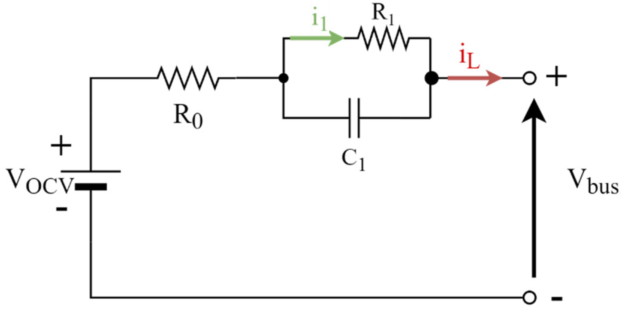
In this work, a lithium-ion battery is considered and modeled via an equivalent circuit model [42]. As depicted in Figure 2, the model is composed of three components: a voltage source , which represents the open circuit voltage (OCV), a resistor , representing the internal resistance, and one RC network, which is connected in series to describe the dynamic behavior of the battery. The nominal parameters of the battery considered in this work are reported in Table 2. The parameters vary with State of Charge (SOC) and temperature (T). Moreover, the thermal behavior of the battery is modeled via a lumped thermal capacity model.

Figure 2.
Schematic of the retained equivalent circuit model.
Table 2.
Nominal battery parameters.
The terminal voltage is computed by applying the Kirchhoff’s voltage law:
while the load current is given by the Kirchhoff’s current law:
and thus
The SOC is equal to:
where is equal to the integral of the current over the entire simulation time. Specifically,
Then, the internal battery temperature is calculated by considering conductive and convective heat transfer:
where m denotes the battery mass, the specific heat capacity, the heat transfer coefficient, the surface area for heat exchange, and and denote air and battery temperatures, respectively.
2.1.2. Fuel Cell System Model
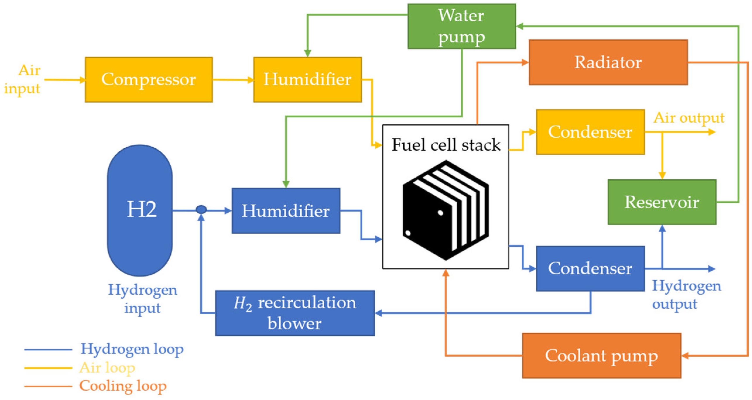
This study considers a PEM fuel cell system derived from [43] and implemented in the Advisor™ 2003 simulation tool embedded in MATLAB® software. It is a quasi-static and semi-empirical model that considers the main electrochemical, fluid-dynamic, and thermal properties of a fuel cell system. Air and fuel supply, fuel cell stack, and coolant loop, as well as humidification and water recovery, are all included in the retained model, as shown in Figure 3.
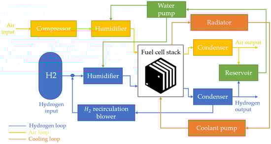
Figure 3.
Schematic of the retained fuel cell system model.
Table 3 shows the fuel cell system specifications.
Table 3.
Fuel cell system specification.
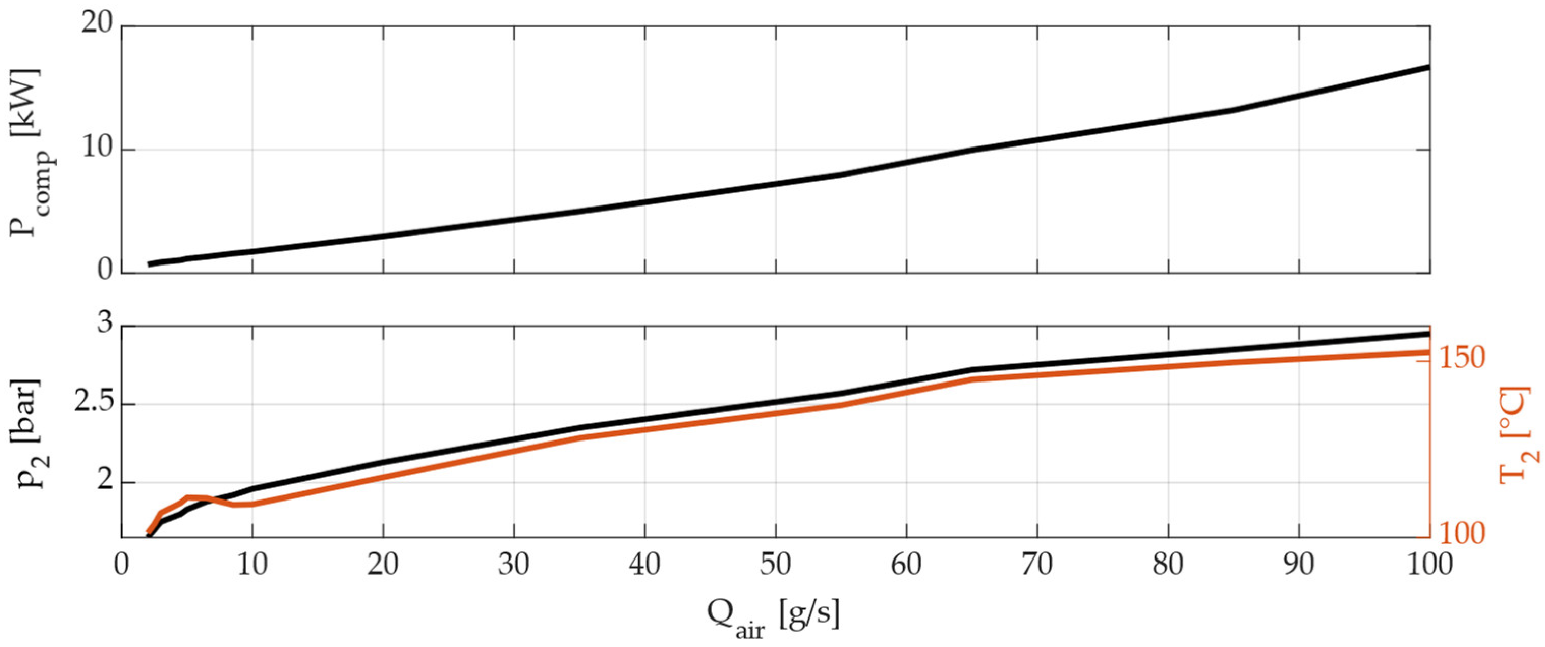
In the air supply sub-system, a model of a twin-screw volumetric air compressor is employed, and its characteristic map is reported in Figure 4. The compressor is supposed to be load-following with respect to the fuel cell system, and thus its pressure output rises as the fuel cell system load grows to deliver the appropriate operating pressure. Separate humidifiers are used to humidify the intake gases. An amount of moisture from the exhaust is collected and reused for humidification purposes once it has been cooled in the condenser. It is important to manage the fuel cell system’s water balance by using water reservoirs, humidifiers, and a condenser to collect exhaust water from the fuel cell stacks and humidify the in-coming flows. The cooling system maintains the fuel cell at optimal operating temperature and releases the heat excess.
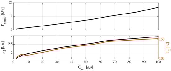
Figure 4.
Twin-screw air compressor map.
The electric power output from the fuel cell stack is computed as:
where is the cell voltage, is the cell current, and the current per cell area, is the cell area, and is the number of cells in the stack.
Except for the air compressor, the parasitic power of the fuel cell auxiliaries is computed by applying Bernoulli’s equation,
where is the fluid flowrate, is the pressure difference between the pipe inlet and outlet, is the fluid density, is the gravitational acceleration, is the height difference between the pipe inlet and outlet, and is the fluid velocity contribution.
The overall power loss due to the auxiliaries is given by:
The fuel cell system efficiency is defined as:
where is the hydrogen consumption [kg/s] and is the hydrogen lower heating value [kWh/kg].
2.2. Energy Management Strategies
To properly determine the target power split of the different FCHV power sources, e.g., fuel cell and battery, it is crucial to design a suitable and reasonable system control strategy. This section presents three different control strategies, namely, constant power, baseline mode-based, and optimal mode-based, for the retained FCHV.
2.2.1. Constant Power
The constant power control strategy enforces the fuel cell working as a range extender for the vehicle. Specifically, the vehicle’s propulsion is mostly delegated to the battery, but the fuel cell may provide extra power to keep the battery charged and boost the vehicle’s range. Since the sizing of the energy storage components did not change, the most convenient level of power delivered by the fuel cell was set on the basis of the mean requested power during the different driving missions. In particular, two different power outputs were set for the low- and high-load drive cycles to complete the drive cycles while reducing fuel consumption properly. For the reasons mentioned above, the power delivered by the fuel cell was set constant at values equal to 5 kW and 12 kW for low-load driving cycles and high-load driving cycles, respectively. Moreover, a charge sustaining mode (CS) was considered for the battery operations.
Referring to Equation (4), the power delivered by the battery is equal to:
in low-load and high-load drive cycles, respectively.
The fuel cell is set to idle during vehicle operation until the battery reaches the lowest desired SOC. Then, once the fuel cell is powered, on the power output is kept constant and equal to the selected value for the remaining simulation time. In this way, there is always enough power from the fuel cell to recharge the battery.
2.2.2. Baseline Mode-Based
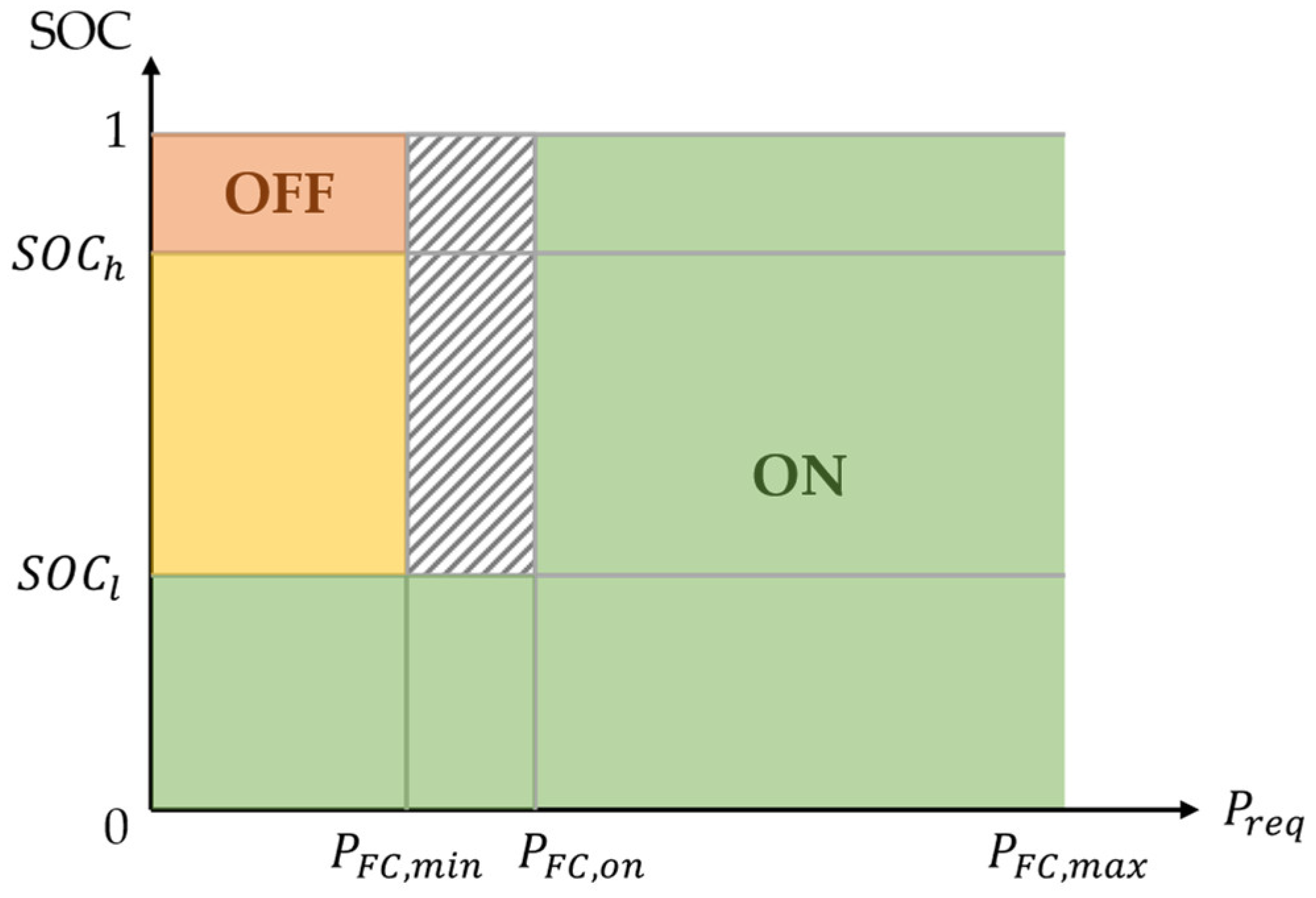
The baseline mode-based control method takes into account a variety of operating modes depending on battery SOC and power needs. The fundamental concept of this power-oriented control strategy is as follows: the fuel cell system is designated as the primary power source, and its output power is controlled to a certain amount in order to match the vehicle’s driving power needs. The fuel cell system is turned on for practically the whole driving period, except for possible initial cold start and when there is minimal driving power demand and the battery pack is at a high state of charge. During the control strategy design, the battery is considered to operate in CS mode and to achieve smooth fuel cell power output transitions, the prior state is checked, and variations are limited. The logic of the baseline mode-based control strategy is shown in Figure 5.
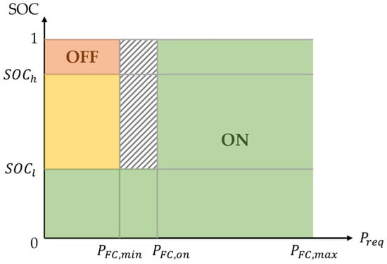
Figure 5.
Baseline mode-based control strategy logic.
In Figure 5, in the green region, the fuel cell is always on, while in the red area, it is always off. The orange region is a transition zone in which the fuel cell retains its on/off state based on its prior condition. During braking, kinetic energy held in the translating mass of the vehicle is stored in the vehicle by using the traction motor as a generator. In this way, braking torque is provided to the wheels and is used to recharge the battery. The target power of the fuel cell system is calculated as:
where and are the minimum and maximum desired values of battery SOC, is the minimum power deliverable by the fuel cell system, is the power at which the fuel cell is started, and is the fuel cell working state at the previous time step.
The main baseline mode-based control strategy parameters are reported in Table 4.
Table 4.
Baseline mode-based control strategy parameters.
2.2.3. Fuzzy Logic Control-Based
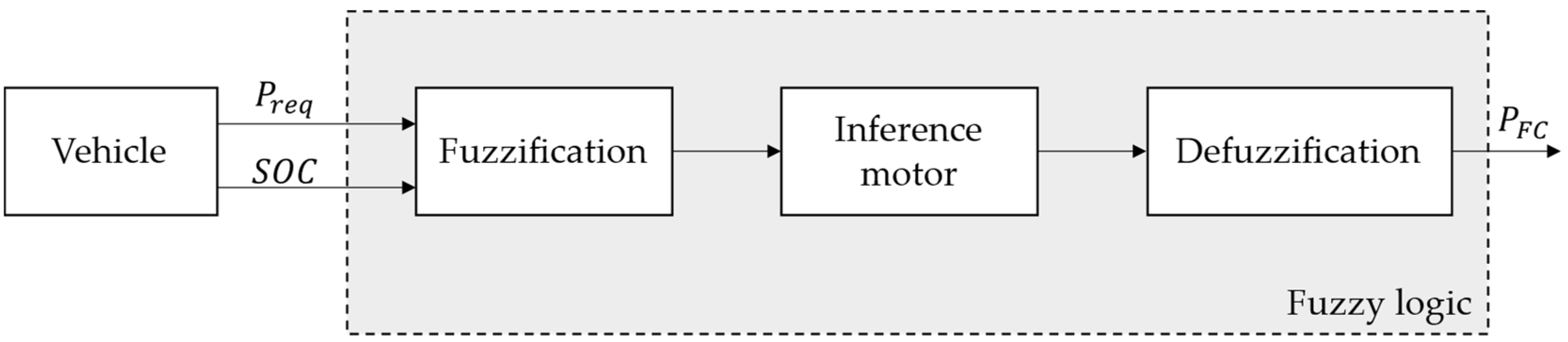
The optimal mode-based control strategy improves the technique presented in the previous subsection by introducing a fuzzy logic technique to control the power split between the vehicle’s battery and fuel cell system. The structure of a fuzzy logic controller is shown in Figure 6. It is divided into three parts: the fuzzification module, the rule-based inference engine, and the defuzzification module.

Figure 6.
General architecture of the fuzzy logic controller.
Fuzzification is the process of converting input into fuzzy subsets. The subsets comprise certain input ranges and membership functions that define the degree of certainty that the input belongs to a given range. The outputs of this block are then sent to the inference engine along with the fuzzy rule base to create control actions. Finally, the defuzzification module processes the output of the inference motor by means of membership functions which determine the output in physical terms.
There are two input variables and one output variable in the retained fuzzy logic controller in the present study. The input variables are the power request and the state of charge (SOC) of the battery while the output variable is the amount of power required to the fuel cell. The power from the battery is then found as the difference between the overall amount of power required by the FCHV and the power generated by the fuel cell system.
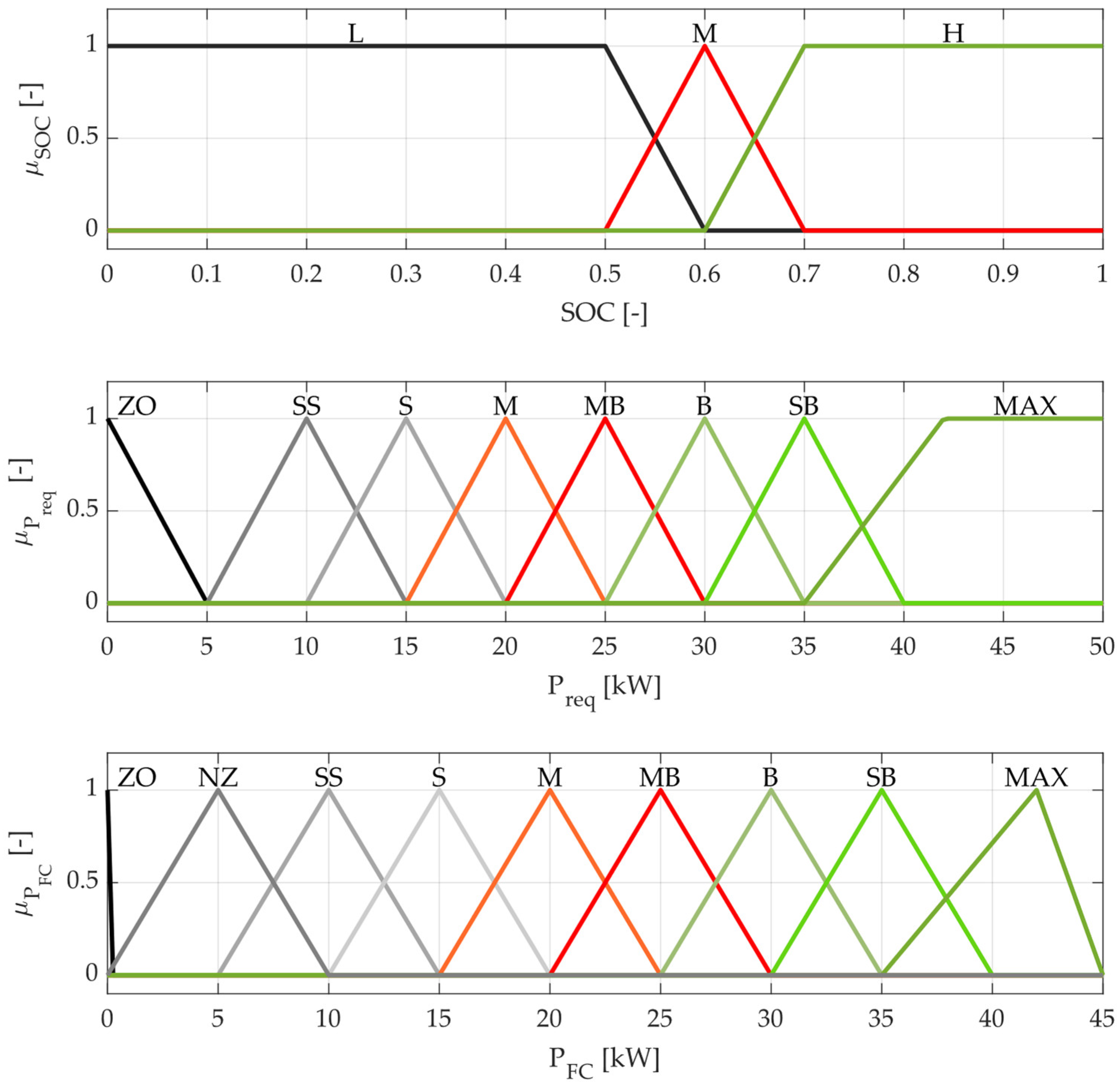
Additionally, the number and shape of the membership functions for each of the fuzzy variables are crucial for increasing fuel cell system efficiency as well as preserving battery charge status, which are critical in a fuzzy logic-based energy management approach. Figure 7 depicts the membership functions of the input and output variables, respectively.
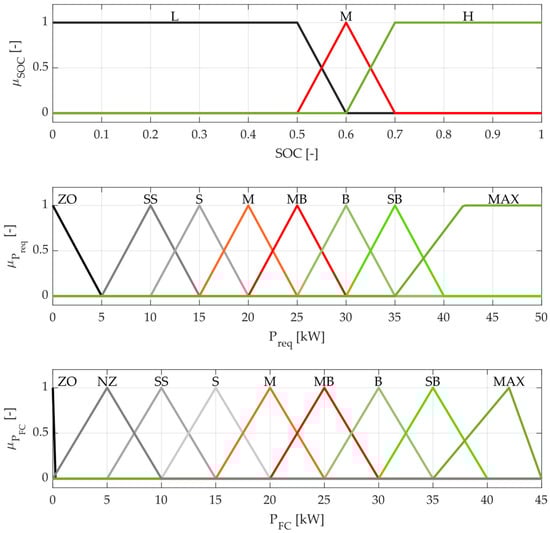
Figure 7.
Membership function of fuzzy logic inputs (, requested power and SOC, battery state of charge) and output (, power to be provided by the fuel cell system).
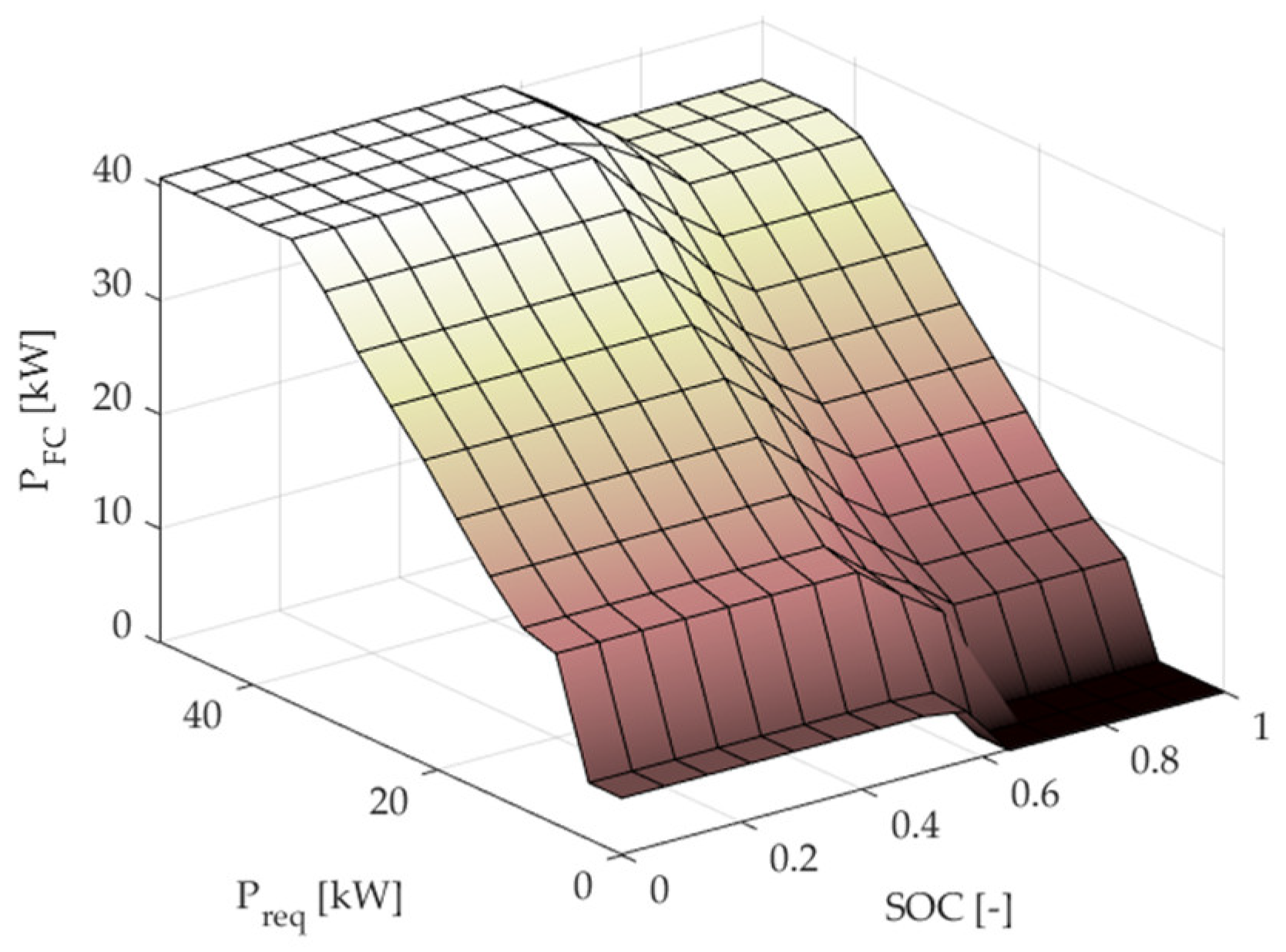
Figure 8 presents a representation of the rule base for the inference motor. This is designed to minimize fuel consumption and maximize the fuel cell system efficiency, while having the net energy drawn from the battery over the drive cycle be as close to zero as possible.
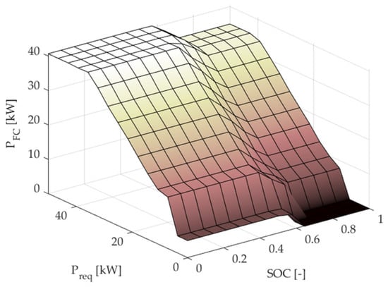
Figure 8.
Tridimensional representation of the fuzzy logic rule base for the inference motor.
3. Results
The presented rule-based control strategies aim to maximize fuel cell system efficiency while minimizing fuel consumption. This section presents the results of the evaluation of the performance of the obtained techniques. Firstly, the performance of the proposed methods was evaluated on the basis of simulations by means of two homologation driving cycles, e.g., New European Driving Cycle (NEDC) and Worldwide harmonized Light vehicles Test Procedure (WLTP). Then, a detailed sensitivity analysis was undertaken to evaluate the fuel cell system efficiency and fuel consumption for the various control techniques in three low-load driving cycles (e.g., FTP, NEDC, UDDS) and two high-load driving cycles (e.g., US06 and WLTP).
3.1. Simulation Results
This section presents the results of the simulations conducted on two standard drive cycles and discusses the performance of the aforementioned control strategies. All the control strategies were implemented in the MATLAB/Simulink environment, while the plant model was modeled in the Simulink environment. When running all of the simulations, equal battery SOC values were imposed at the start and end of each driving cycle.
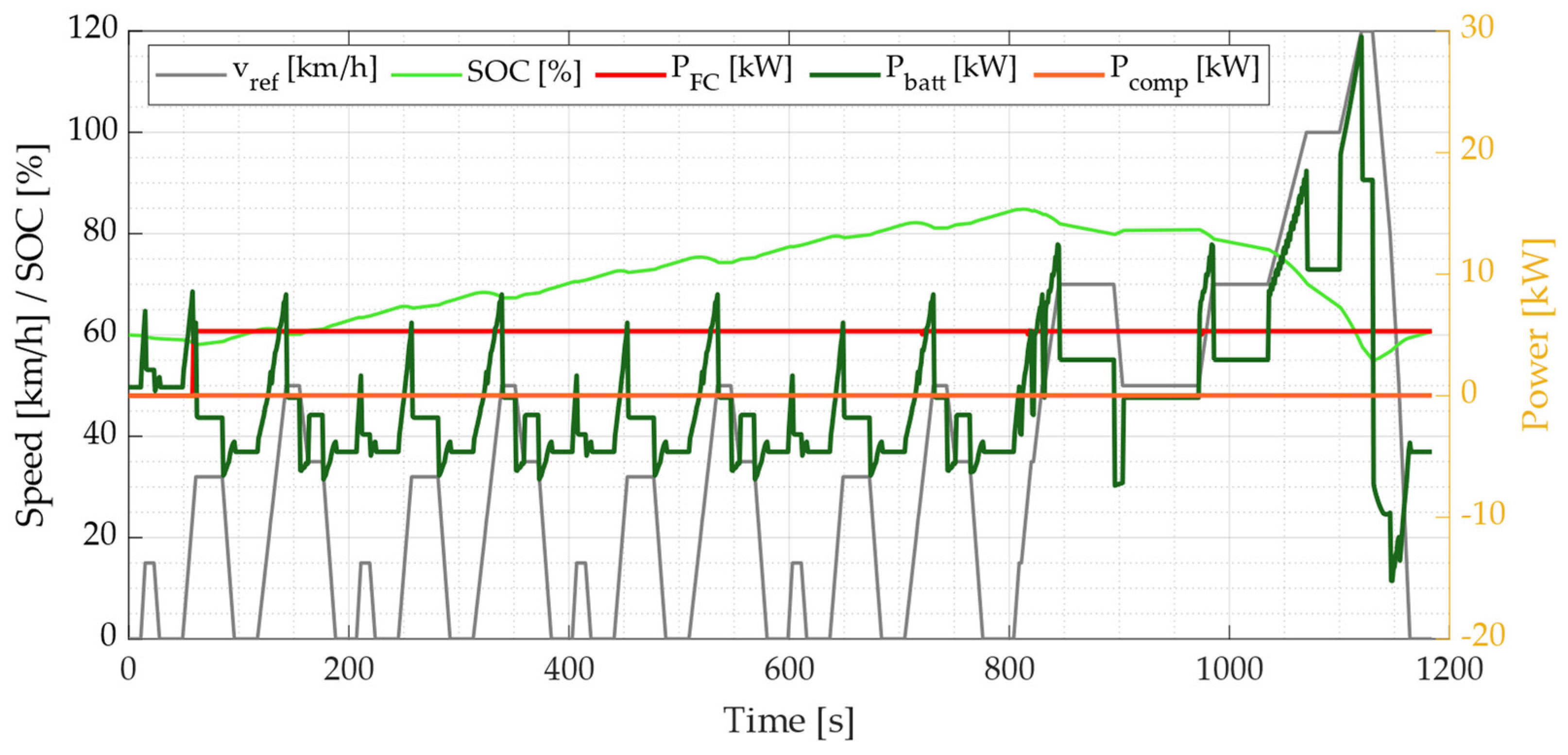
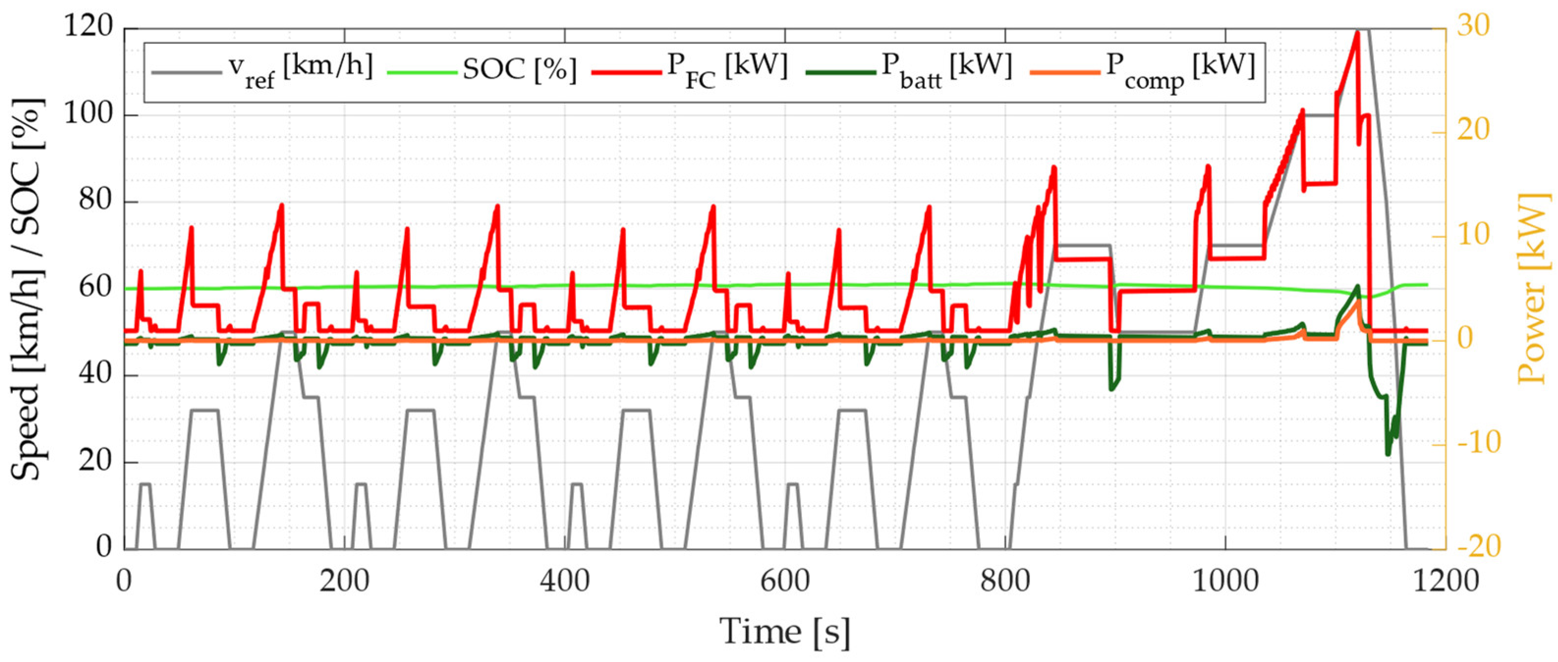
Figure 9, Figure 10 and Figure 11 present the results for the NEDC drive cycle. Each figure shows the reference speed profile (grey solid line) and SOC profile (green solid line) on the left y-axis and the fuel cell power (red solid line), battery power (dark green solid line) and compressor power (black solid line) on the right y-axis.
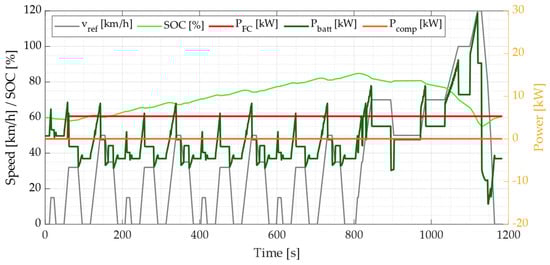
Figure 9.
Simulation conducted on NEDC driving cycle with constant power control strategy.
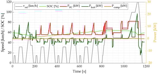
Figure 10.
Simulation conducted on NEDC driving cycle with baseline mode-based control strategy.
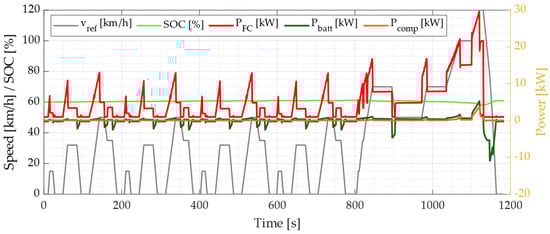
Figure 11.
Simulation conducted on NEDC driving cycle with fuzzy logic control strategy.
Figure 9 presents the constant power control strategy. The fuel cell is kept idle until the SOC reaches the minimum allowable value. Starting from this instant, the fuel cell is turned on until the end of the cycle, and the delivered power is equal to 5 kW.
Figure 10 presents the baseline rule-based control strategy. The fuel cell is kept idle until the SOC reaches the minimum allowable value stated in Table 4. Starting from this instant, the fuel cell is turned on until the end of the cycle. The delivered power varies accordingly to the rules reported in Figure 5. The fuel cell compressor power is always below 100 W.
Figure 11 refers to the fuzzy logic control strategy. In this particular case, the fuel cell is immediately turned on, and the provided power is computed according to the rules reported in Figure 7. In contrast to the previous control strategies, the SOC profile is stable around 60%, which is the initial SOC value. Since the fuel cell is used more dynamically, also the compressor power increases up to 1.5 kW.
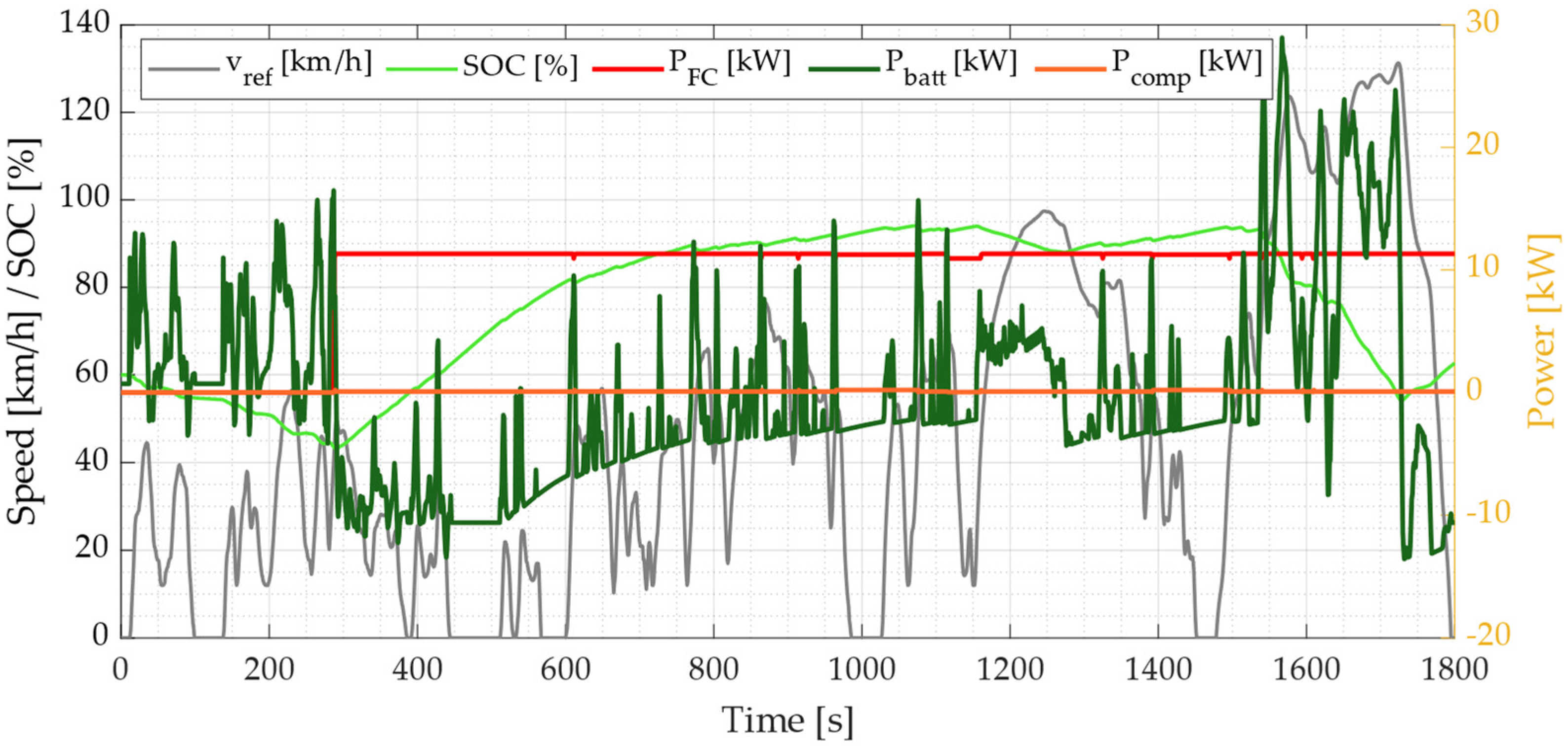
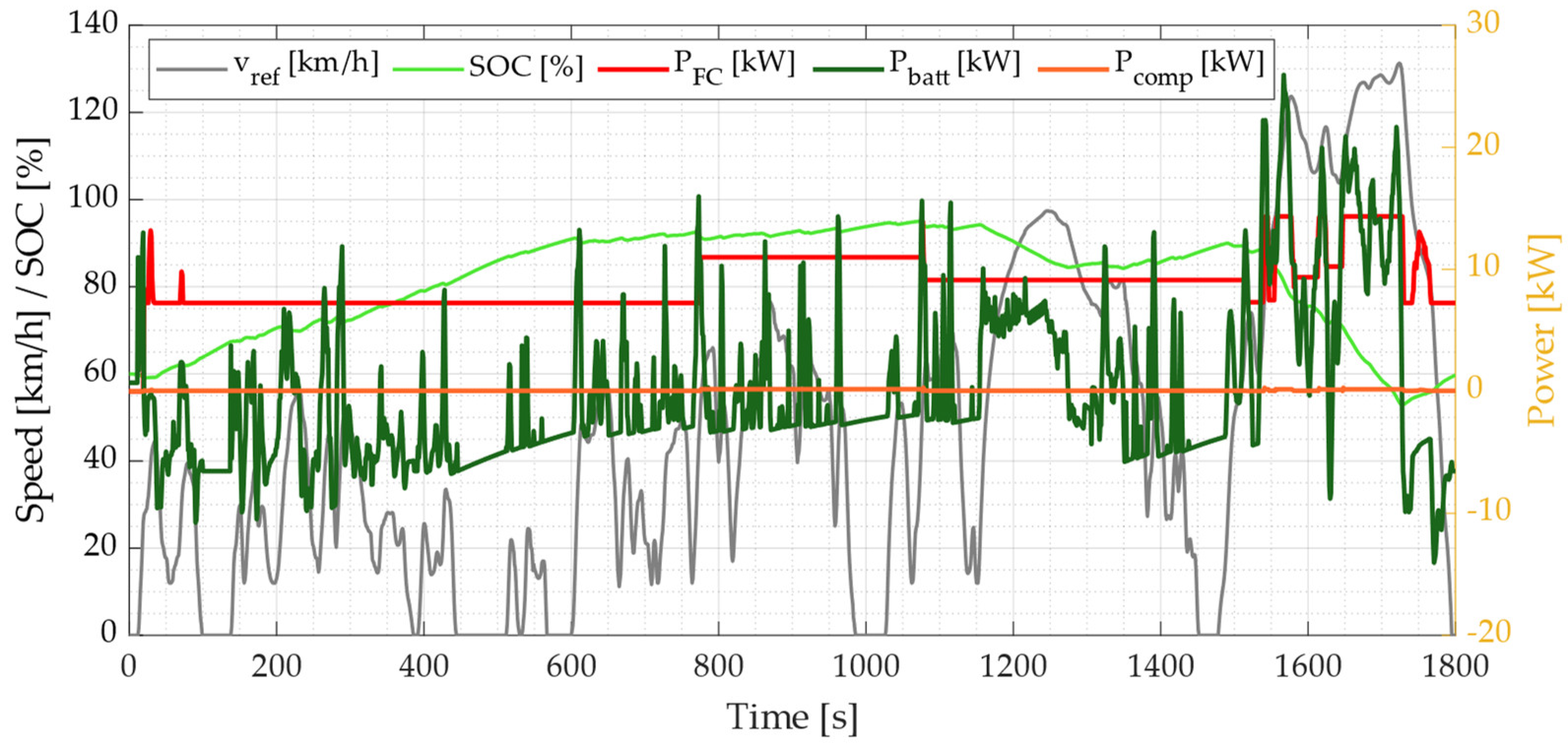
Figure 12, Figure 13 and Figure 14 present the results for the WLTP drive cycle. Each figure shows the reference speed profile (grey solid line) and SOC profile (green solid line) on the left y-axis and the fuel cell power (red solid line), battery power (dark green solid line) and compressor power (black solid line) on the right y-axis.
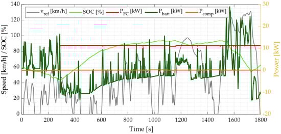
Figure 12.
Simulation conducted on WLTP driving cycle with constant power control strategy.
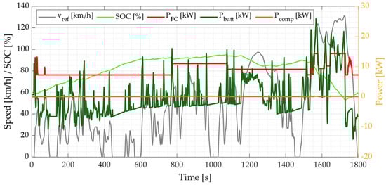
Figure 13.
Simulation conducted on WLTP driving cycle with baseline mode-based control strategy.
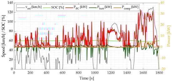
Figure 14.
Simulation conducted on WLTP driving cycle with fuzzy logic control strategy.
Figure 12 presents the constant power control strategy. The fuel cell is kept idle until the SOC reaches the minimum allowable value. Starting from this instant, the fuel cell is turned on until the end of the cycle and the delivered power is equal to 12 kW. Figure 13 presents the baseline rule-based control strategy. The fuel cell is kept idle until the SOC reaches the minimum allowable value stated in Table 4. Starting from this instant, the fuel cell is turned on until the end of the cycle. The delivered power varies according to the rules presented in Figure 5. The fuel cell compressor power is always below 100 W.
Figure 14 presents the fuzzy logic control strategy. In this particular case, the fuel cell is immediately turned on and the provided power is computed according to the rules reported in Figure 7. In contrast to the previous control strategies, the SOC profile is stable at around 60% for almost the whole cycle. Since the fuel cell is used more dynamically and the drive cycle is more expensive in terms of requested power, the compressor power increases to 2.5 kW in the last part of the drive cycle.
3.2. Control Strategy Performance Analysis
To visualize the above results more effectively, it is convenient to show more precisely to which degree the different control strategies improve or deteriorate the FCHV performance in terms of equivalent consumption and fuel cell system efficiency. To this end, three low-load drive cycles and three high-load drive cycles are considered.
The equivalent consumption is computed on the basis of the ISO 23274-1 standard. Unless the energy battery fluctuation at cycle start and end is more than 1% of the energy associated with fuel used throughout cycle, the standard does not require any modifications to the observed fuel consumption (e.g., hydrogen usage). Thus, the equivalent fuel consumption is given by
where is the hydrogen consumption and is the corrective factor for the battery and is equal to the ratio of fuel cell energy fluctuation across the whole drive cycle to battery energy variation at the start and end of the drive cycle.
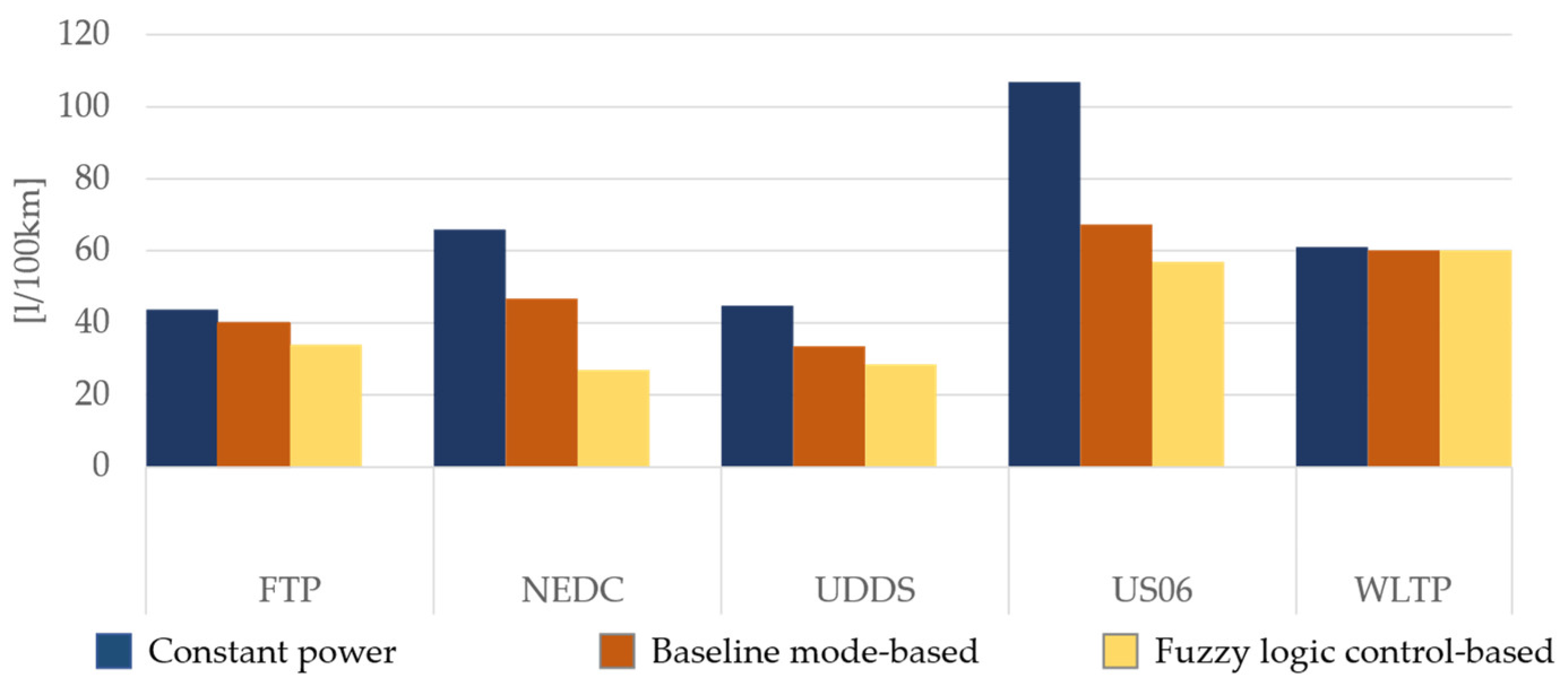
Figure 15 shows the equivalent fuel consumption per 100 km for each control strategy in six different drive cycles. The constant power control strategy is the one with the highest fuel consumption, up to 108 L/100 km in the US06 drive cycle. Then, the fuzzy logic control strategy performs better when compared to the constant power and baseline rule-based control strategies. Nevertheless, when the WLTP drive cycle is considered, the results are comparable.
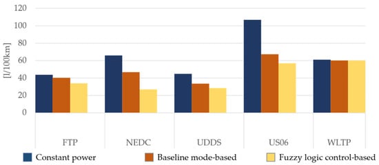
Figure 15.
Comparison of equivalent consumption per 100 km [L/100 km].
Figure 16 shows the equivalent fuel cell system efficiency for each control strategy in six different drive cycles. The constant power control strategy shows quite high fuel cell system efficiency due to the low compressor use. Afterwards, the fuzzy logic control strategy shows improved fuel cell system efficiency when compared to the constant power and baseline rule-based control strategies. The fuel cell system efficiency increases by 33% in low-load drive cycles and 12% in high-load drive cycles. Nevertheless, when WLTP drive cycle is considered the results are comparable and it is coherent to the results reported in Figure 15. Please note that despite the reduced regenerative braking when the fuzzy logic control strategy is applied, the better efficiency given by this control logic leads to a decrease in energy consumption as shown in Figure 15.
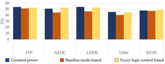
Figure 16.
Comparison of fuel cell system efficiency [%].
4. Conclusions
In this paper, the design and assessment of three different control strategies for energy management in FCEVs was presented. The study was specifically conducted to define how much the fuel cell system efficiency can be improved and how much hydrogen can be saved by using a rule-based energy management strategy to control the power and energy split between the fuel cell and the battery.
Specifically, the novel contribution of this paper was the analysis of three different control strategies, namely, constant power, baseline mode-based and optimal mode-based, in an FCEV using a semi-empirical model for the fuel cell system. The performance and adjustments of these strategies were evaluated in terms of fuel cell system efficiency and fuel consumption. The results were obtained on the basis of simulations of five different drive cycles.
A passenger FCEV was modeled via a forward approach. The fuel cell system was modeled by means of a semi-empirical model in consideration of both the influence of different auxiliary systems and the thermal and water management of the system. To guarantee an adequate power and energy split between the fuel cell and battery, three control strategies were analyzed. The first one imposed a constant power flow from the fuel cell, while the remaining two implemented rule-based control strategies. The results showed that in both low-load cycles (FTP, NEDC, UDDS) and high-load cycles (US06 and WLTP), the best control strategy maintained a fuel cell system efficiency equal to or greater than 33%, while the fuel consumption was 30% and 20% less with respect to the baseline control strategy in low-load and high-load drive cycles, respectively.
This work proposed a systematic approach for assessing the performance of rule-based energy management strategies for FCEVs in terms of fuel cell system efficiency and fuel consumption minimization. The methodology could be further improved by adding consideration about the FCEV lifetime components, with the purpose of making this platform more affordable. Then, an extensive experimental validation phase on real FCEVs could be performed. Nevertheless, the proposed methodology is general, and can be applied in a wide range of energy management scenarios in FCEVs.
Author Contributions
Conceptualization and methodology, A.T., S.L.; software, S.L.; writing—original draft preparation, S.L.; writing—review and editing, S.L. and A.T.; supervision, A.T. All authors have read and agreed to the published version of the manuscript.
Funding
This research received no external funding.
Acknowledgments
This work was developed in the framework of the activities of the Interdepartmental Center for Automotive Research and Sustainable Mobility (CARS) at Politecnico di Torino (www.cars.polito.it, accessed on 16 February 2022).
Conflicts of Interest
The authors declare no conflict of interest.
Abbreviations
| FCHV | Fuel cell hybrid vehicle |
| PEM | Proton-exchange membrane fuel cell |
| ICE | Internal combustion engine |
| EV | Electric vehicle |
| FTP | Federal test procedure |
| NEDC | New European driving cycle |
| UDDS | Urban dynamometer driving schedule |
| US06 | Supplemental federal Test Procedure |
| WLTP | Worldwide harmonized light-duty vehicle test procedure |
| OCV | Open circuit voltage |
| SOC | State of charge |
| LHV | Lower heating value |
| CS | Charge sustaining |
References
- Ajanovic, A.; Haas, R. Economic and environmental prospects for battery electric-and fuel cell vehicles: A review. Fuel Cells 2019, 19, 515–529. [Google Scholar] [CrossRef] [Green Version]
- Bishop, J.; Martin, N.P.; Boies, A.M. Cost-effectiveness of alternative powertrains for reduced energy use and CO2 emissions in passenger vehicles. Appl. Energy 2014, 124, 44–61. [Google Scholar] [CrossRef]
- Tanç, B.; Arat, H.T.; Baltacıoğlu, E.; Aydın, K. Overview of the next quarter century vision of hydrogen fuel cell electric vehicles. Int. J. Hydrogen Energy 2019, 44, 10120–10128. [Google Scholar] [CrossRef]
- Thomas, C. Fuel cell and battery electric vehicles compared. Int. J. Hydrogen Energy 2009, 34, 6005–6020. [Google Scholar] [CrossRef] [Green Version]
- Khaligh, A.; Li, Z. Battery, Ultracapacitor, Fuel Cell, and Hybrid Energy Storage Systems for Electric, Hybrid Electric, Fuel Cell, and Plug-In Hybrid Electric Vehicles: State of the Art. IEEE Trans. Veh. Technol. 2010, 59, 2806–2814. [Google Scholar] [CrossRef]
- Hames, Y.; Kaya, K.; Baltacioglu, E.; Turksoy, A. Analysis of the control strategies for fuel saving in the hydrogen fuel cell vehicles. Int. J. Hydrogen Energy 2018, 43, 10810–10821. [Google Scholar] [CrossRef]
- Bethoux, O. Hydrogen Fuel Cell Road Vehicles: State of the Art and Perspectives. Energies 2020, 13, 5843. [Google Scholar] [CrossRef]
- Zhao, H.; Burke, A. Fuel Cell Powered Vehicles. In Encyclopedia of Automotive Engineering; Wiley: Hoboken, NJ, USA, 2013; pp. 1–18. [Google Scholar]
- Carello, M.; Pinheiro, H.D.C.; Longega, L.; Di Napoli, L. Design and Modelling of the Powertrain of a Hybrid Fuel Cell Electric Vehicle. SAE Tech. Pap. Ser. 2021, 3, 2878–2892. [Google Scholar] [CrossRef]
- Hilkert, M. Pathways for a Transition to a Sustainable Hydrogen Transportation Fuel Infrastructure in California; Karlsruhe Institute of Technology (KIT): Karlsruhe, Germany, 2004. [Google Scholar]
- Davis, S.C.; Williams, S.E.; Boundy, R.G.; Moore, S.A. 2016 Vehicle Technologies Market Report; Oak Ridge National Laboratory: Oak Ridge, TN, USA, 2017. [Google Scholar]
- Xu, N.; Kong, Y.; Chu, L.; Ju, H.; Yang, Z.; Xu, Z.; Xu, Z. Towards a Smarter Energy Management System for Hybrid Vehicles: A Comprehensive Review of Control Strategies. Appl. Sci. 2019, 9, 2026. [Google Scholar] [CrossRef] [Green Version]
- Biswas, A.; Emadi, A. Energy Management Systems for Electrified Powertrains: State-of-the-Art Review and Future Trends. IEEE Trans. Veh. Technol. 2019, 68, 6453–6467. [Google Scholar] [CrossRef]
- Tran, D.-D.; Vafaeipour, M.; El Baghdadi, M.; Barrero, R.; Van Mierlo, J.; Hegazy, O. Thorough state-of-the-art analysis of electric and hybrid vehicle powertrains: Topologies and integrated energy management strategies. Renew. Sustain. Energy Rev. 2020, 119, 109596. [Google Scholar] [CrossRef]
- Odeim, F.; Roes, J.; Heinzel, A. Power Management Optimization of an Experimental Fuel Cell/Battery/Supercapacitor Hybrid System. Energies 2015, 8, 6302–6327. [Google Scholar] [CrossRef] [Green Version]
- Santucci, A.; Sorniotti, A.; Lekakou, C. Power split strategies for hybrid energy storage systems for vehicular applications. J. Power Sources 2014, 258, 395–407. [Google Scholar] [CrossRef] [Green Version]
- Sundstrom, O.; Stefanopoulou, A. Optimal power split in fuel cell hybrid electric vehicle with different battery sizes, drive cycles, and objectives. In Proceedings of the 2006 IEEE Conference on Computer Aided Control System Design, 2006 IEEE International Conference on Control Applications, 2006 IEEE International Symposium on Intelligent Control, Munich, Germany, 4–6 October 2006; pp. 1681–1688. [Google Scholar]
- Enang, W.; Bannister, C. Modelling and control of hybrid electric vehicles (A comprehensive review). Renew. Sustain. Energy Rev. 2017, 74, 1210–1239. [Google Scholar] [CrossRef] [Green Version]
- Anselma, P. Optimization-Driven Powertrain-Oriented Adaptive Cruise Control to Improve Energy Saving and Passenger Comfort. Energies 2021, 14, 2897. [Google Scholar] [CrossRef]
- Anselma, P.G.; Kollmeyer, P.; Lempert, J.; Zhao, Z.; Belingardi, G.; Emadi, A. Battery state-of-health sensitive energy management of hybrid electric vehicles: Lifetime prediction and ageing experimental validation. Appl. Energy 2021, 285, 116440. [Google Scholar] [CrossRef]
- Hemi, H.; Ghouili, J.; Cheriti, A. Combination of Markov chain and optimal control solved by Pontryagin’s Minimum Principle for a fuel cell/supercapacitor vehicle. Energy Convers. Manag. 2015, 91, 387–393. [Google Scholar] [CrossRef]
- Peng, H.; Chen, Z.; Li, J.; Deng, K.; Dirkes, S.; Gottschalk, J.; Ünlübayir, C.; Thul, A.; Löwenstein, L.; Pischinger, S.; et al. Offline optimal energy management strategies considering high dynamics in batteries and constraints on fuel cell system power rate: From analytical derivation to validation on test bench. Appl. Energy 2021, 282, 116152. [Google Scholar] [CrossRef]
- Han, J.; Park, Y.; Kum, D. Optimal adaptation of equivalent factor of equivalent consumption minimization strategy for fuel cell hybrid electric vehicles under active state inequality constraints. J. Power Sources 2014, 267, 491–502. [Google Scholar] [CrossRef]
- Zhang, W.; Li, J.; Xu, L.; Ouyang, M. Optimization for a fuel cell/battery/capacity tram with equivalent consumption minimization strategy. Energy Convers. Manag. 2017, 134, 59–69. [Google Scholar] [CrossRef]
- Rahmeh, H.; Bonfitto, A.; Ruzimov, S. Fuzzy Logic vs Equivalent Consumption Minimization Strategy for Energy Management in P2 Hybrid Electric Vehicles. In International Design Engineering Technical Conferences and Computers and Information in Engineering Conference; American Society of Mechanical Engineers: New York, NY, USA, 2020; Volume 83938, p. V004T04A026. [Google Scholar]
- Hegde, S.; Bonfitto, A.; Rahmeh, H.; Amati, N.; Tonoli, A. Optimal Selection of Equivalence Factors for ECMS in Mild Hybrid Electric Vehicles. In International Design Engineering Technical Conferences and Computers and Information in Engineering Conference; American Society of Mechanical Engineers: New York, NY, USA, 2021; Volume 85369, p. V001T01A019. [Google Scholar]
- Amin; Bambang, R.T.; Rohman, A.S.; Dronkers, C.J.; Ortega, R.; Sasongko, A. Energy Management of Fuel Cell/Battery/Supercapacitor Hybrid Power Sources Using Model Predictive Control. IEEE Trans. Ind. Inform. 2014, 10, 1992–2002. [Google Scholar] [CrossRef]
- Ezemobi, E.; Yakhshilikova, G.; Ruzimov, S.; Castellanos, L.M.; Tonoli, A. Adaptive Model Predictive Control Including Battery Thermal Limitations for Fuel Consumption Reduction in P2 Hybrid Electric Vehicles. World Electr. Veh. J. 2022, 13, 33. [Google Scholar] [CrossRef]
- Zhou, Y.; Ravey, A.; Péra, M.-C. Real-time cost-minimization power-allocating strategy via model predictive control for fuel cell hybrid electric vehicles. Energy Convers. Manag. 2021, 229, 113721. [Google Scholar] [CrossRef]
- Pereira, D.F.; Lopes, F.D.C.; Watanabe, E.H. Nonlinear Model Predictive Control for the Energy Management of Fuel Cell Hybrid Electric Vehicles in Real Time. IEEE Trans. Ind. Electron. 2021, 68, 3213–3223. [Google Scholar] [CrossRef]
- Hofman, T.; Steinbuch, M.; Van Druten, R.; Serrarens, A. Rule-based energy management strategies for hybrid vehicles. Int. J. Electr. Hybrid Veh. 2007, 1, 71. [Google Scholar] [CrossRef]
- Ehsani, M.; Gao, Y.; Longo, S.; Ebrahimi, K.M. Modern Electric, Hybrid Electric, and Fuel Cell Vehicles; CRC Press: Boca Raton, FL, USA, 2018. [Google Scholar]
- Li, Q.; Su, B.; Pu, Y.; Han, Y.; Wang, T.; Yin, L.; Chen, W. A State Machine Control Based on Equivalent Consumption Minimization for Fuel Cell/ Supercapacitor Hybrid Tramway. IEEE Trans. Transp. Electrif. 2019, 5, 552–564. [Google Scholar] [CrossRef]
- Radica, G.; Tolj, I.; Markota, D.; Lototskyy, M.V.; Pasupathi, S.; Yartys, V. Control strategy of a fuel-cell power module for electric forklift. Int. J. Hydrogen Energy 2021, 46, 35938–35948. [Google Scholar] [CrossRef]
- Trovão, J.P.F.; Pereirinha, P.J.G. Control scheme for hybridised electric vehicles with an online power follower management strategy. IET Electr. Syst. Transp. 2015, 5, 12–23. [Google Scholar] [CrossRef]
- Li, C.-Y.; Liu, G.-P. Optimal fuzzy power control and management of fuel cell/battery hybrid vehicles. J. Power Sources 2009, 192, 525–533. [Google Scholar] [CrossRef]
- Wu, J.; Zhang, C.-H.; Cui, N.-X. Fuzzy energy management strategy for a hybrid electric vehicle based on driving cycle recognition. Int. J. Automot. Technol. 2012, 13, 1159–1167. [Google Scholar] [CrossRef]
- Hemi, H.; Ghouili, J.; Cheriti, A. A real time fuzzy logic power management strategy for a fuel cell vehicle. Energy Convers. Manag. 2014, 80, 63–70. [Google Scholar] [CrossRef]
- Derakhshan, M.; Shirazi, K.H. Optimized fuzzy controller for a power–torque distribution in a hybrid vehicle with a parallel configuration. Proc. Inst. Mech. Eng. Part D J. Automob. Eng. 2014, 228, 1654–1674. [Google Scholar] [CrossRef]
- Zhang, P.; Yan, F.; Du, C. A comprehensive analysis of energy management strategies for hybrid electric vehicles based on bibliometrics. Renew. Sustain. Energy Rev. 2015, 48, 88–104. [Google Scholar] [CrossRef]
- ISO 23274-1; Hybrid-Electric Road Vehicles—Exhaust Emissions and Fuel Consumption Measurements—Part 1: Non-Externally Chargeable Vehicles. ISO: Geneva, Switzerland, 2019.
- Tudoroiu, R.E.; Zaheeruddin, M.; Tudoroiu, N.; Radu, S.M. SOC Estimation of a Rechargeable Li-Ion Battery Used in Fuel-Cell Hybrid Electric Vehicles—Comparative Study of Accuracy and Robustness Performance Based on Statistical Criteria. Part I: Equivalent Models. Batteries 2020, 6, 42. [Google Scholar] [CrossRef]
- Haraldsson, K.; Alvfors, P. Effects of ambient conditions on fuel cell vehicle performance. J. Power Sources 2005, 145, 298–306. [Google Scholar] [CrossRef]


Publisher’s Note: MDPI stays neutral with regard to jurisdictional claims in published maps and institutional affiliations. |
© 2022 by the authors. Licensee MDPI, Basel, Switzerland. This article is an open access article distributed under the terms and conditions of the Creative Commons Attribution (CC BY) license (https://creativecommons.org/licenses/by/4.0/).