
Semi-Polycrystalline–Polyaniline Empowered Electrochemical Capacitor


Abstract
:1. Introduction
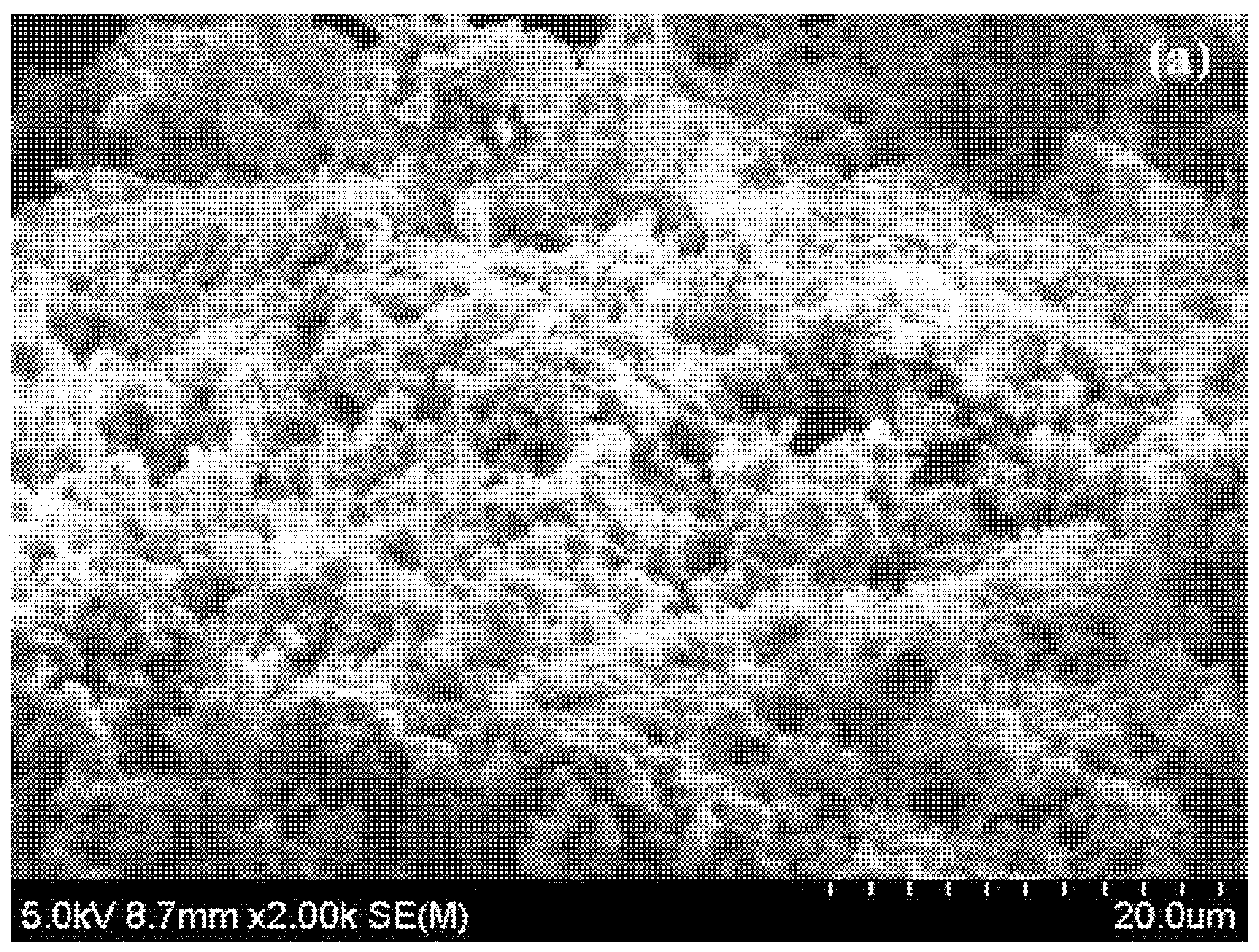
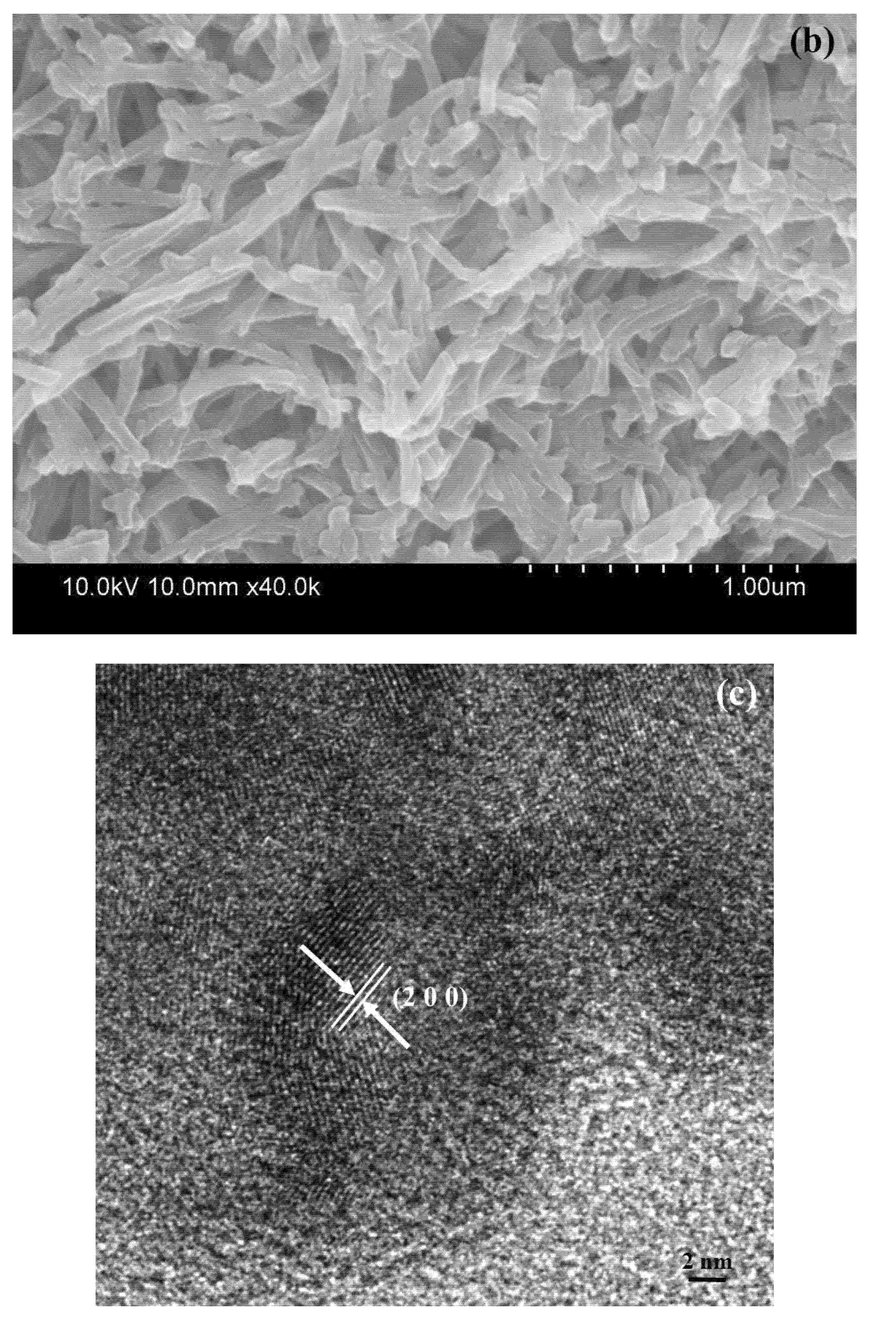
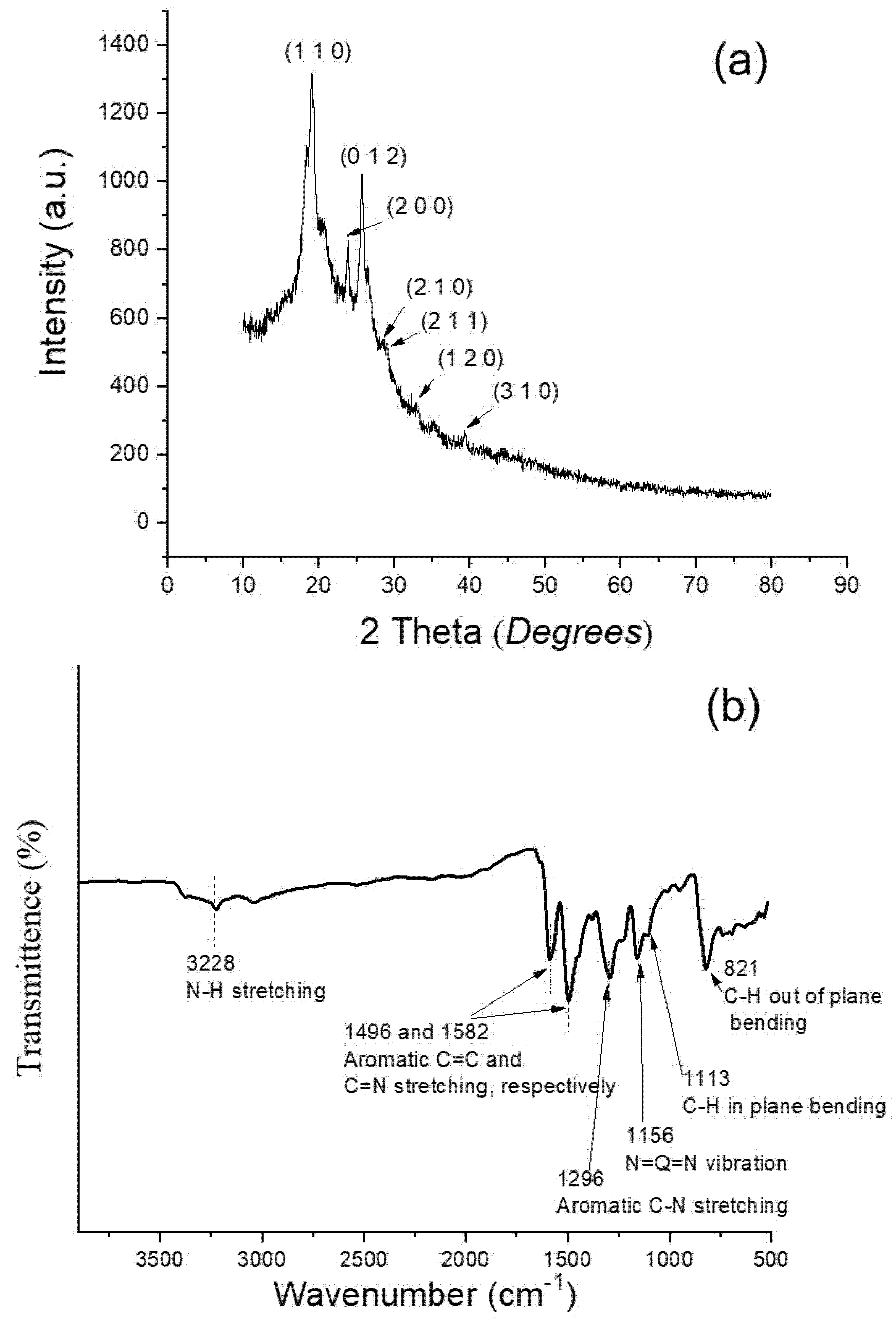
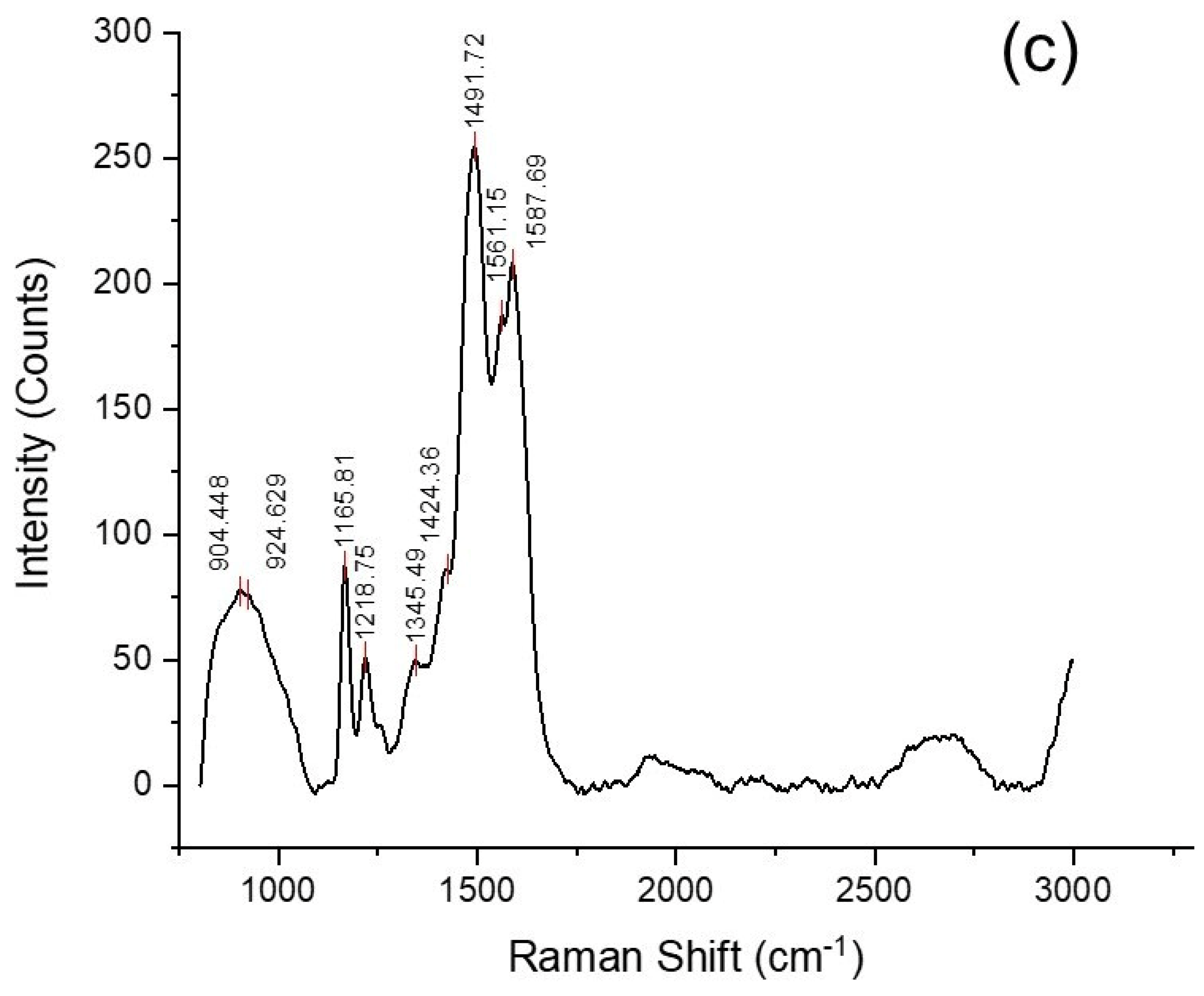
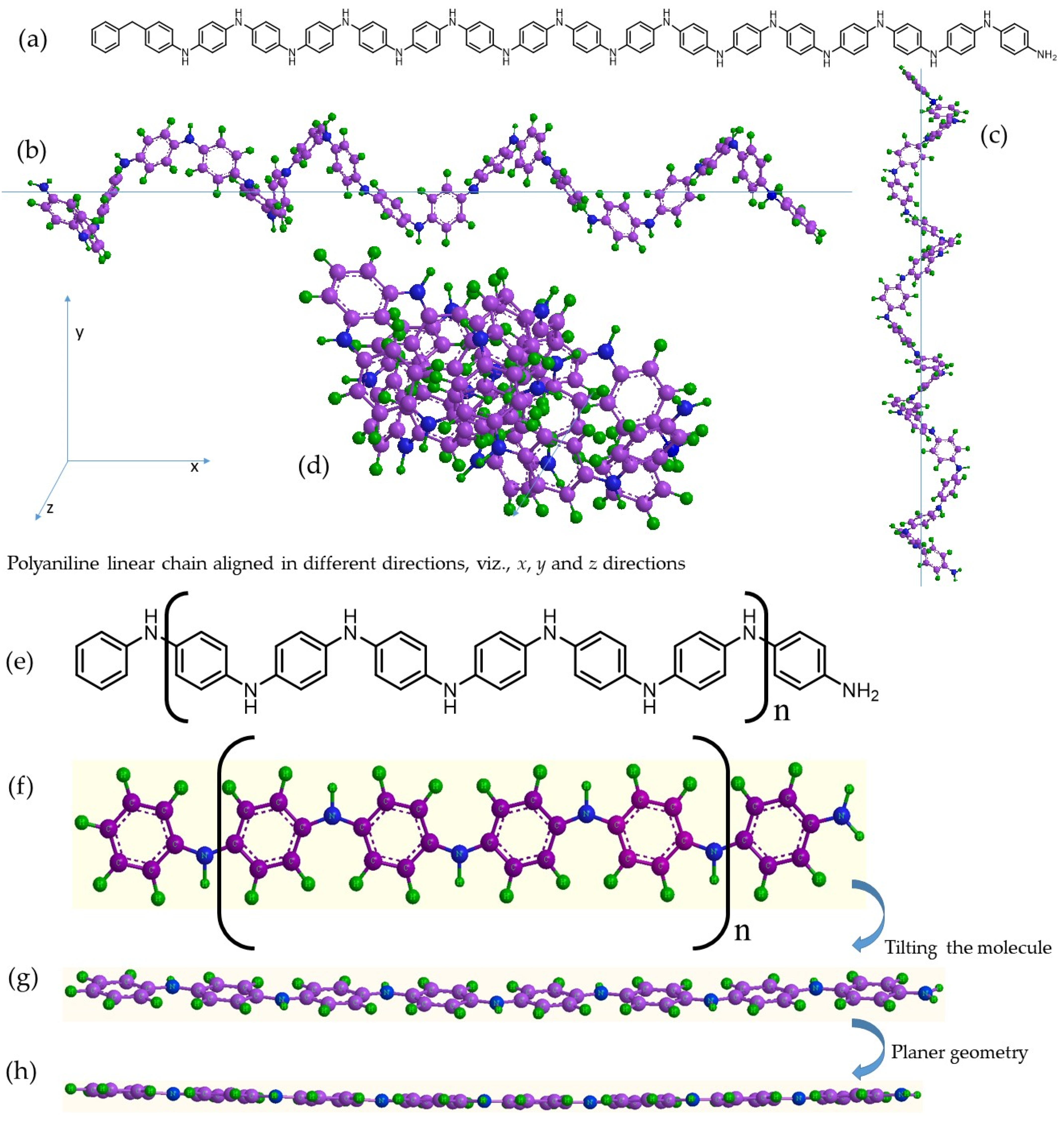
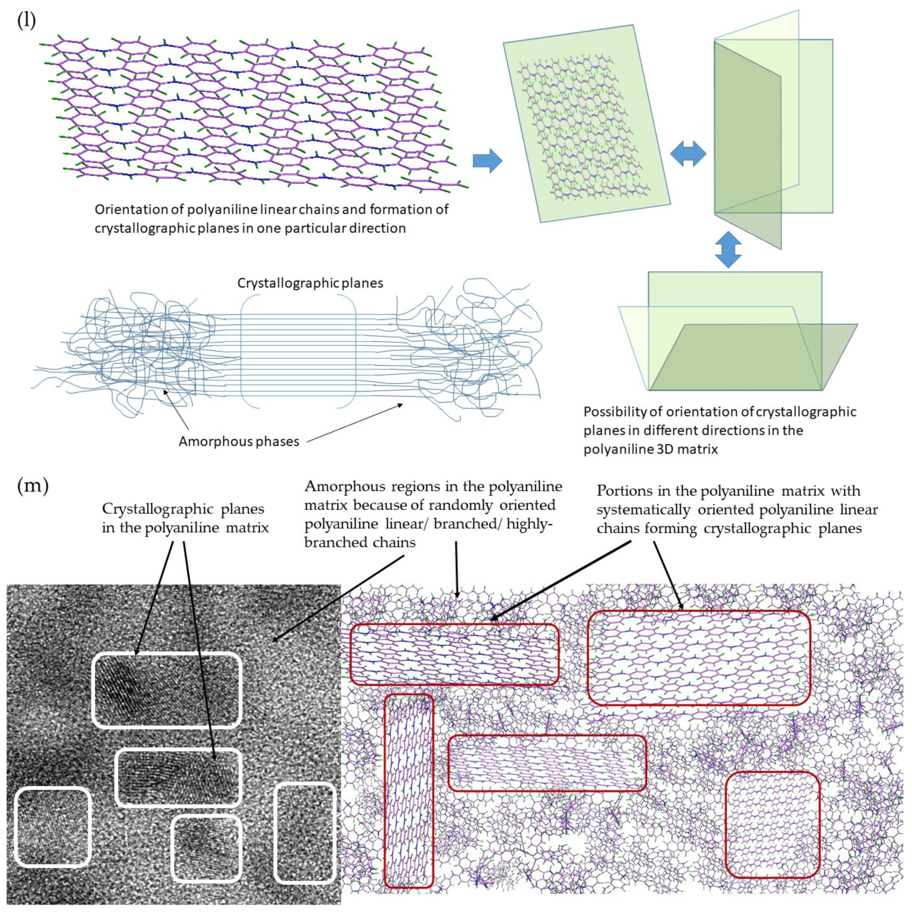
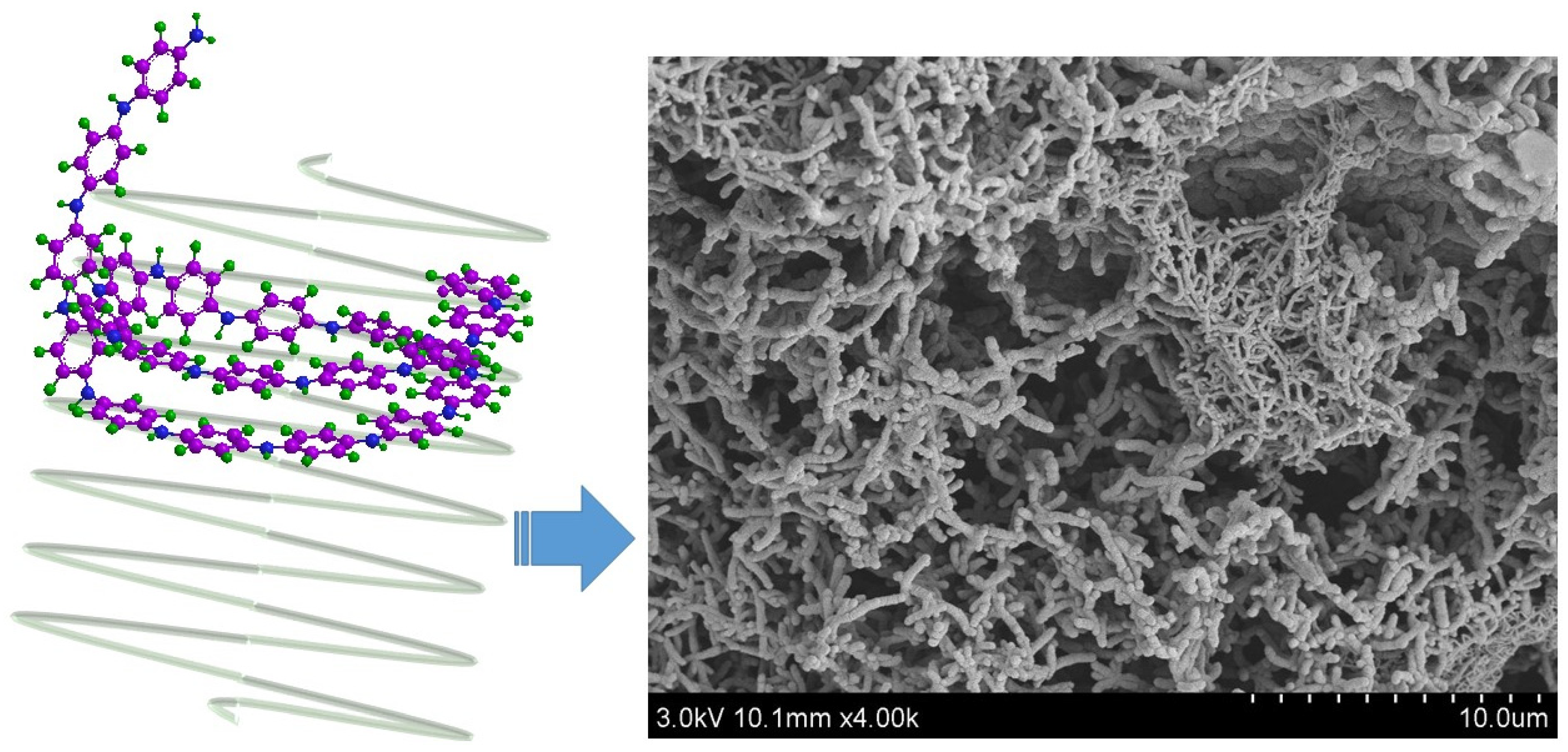
- (a)
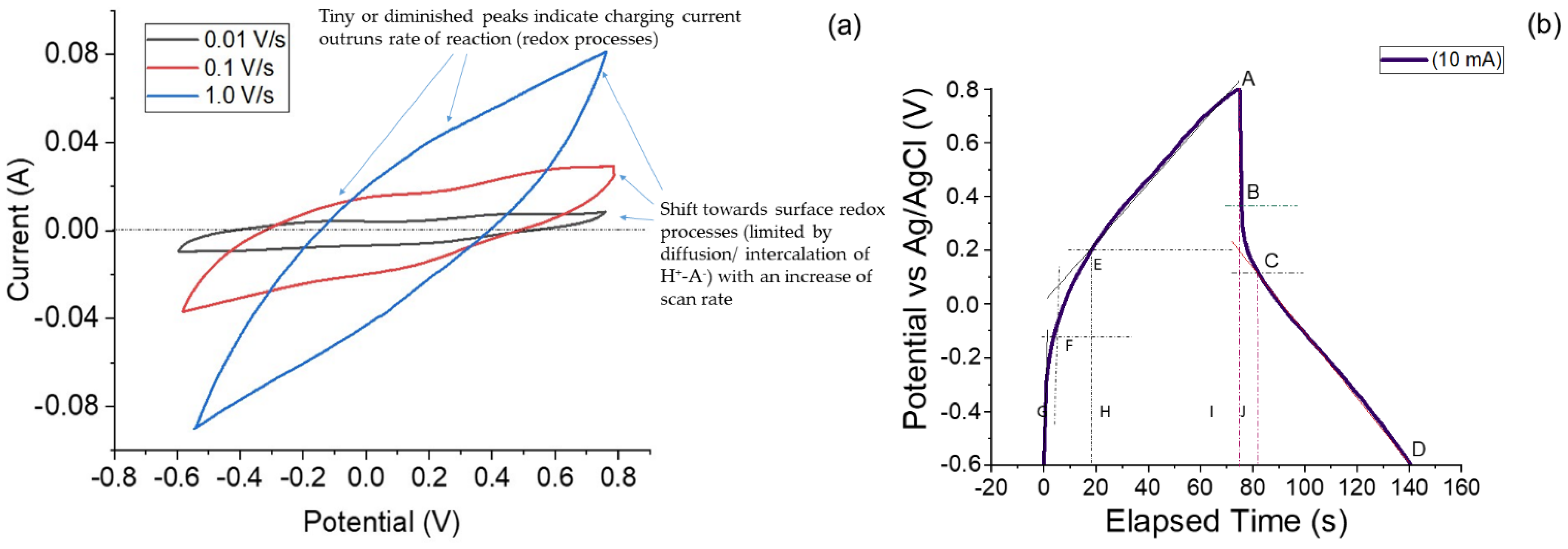
- Capacitive or ideal double layer or non-Faradaic charge storage: This type of charge storage takes place due to formation of an electrical double layer at the interface of an electronically conducting phase (electrode) and an ionically conducting phase (i.e., electrolyte). The actual charges, or electrons, in excess or deficiency are accumulated on the electrode material, and the positive charges reside in the electrolyte medium at the vicinity next to the electrode. There occurs no chemical reaction (or redox reaction/Faradaic reaction), i.e., change in the oxidation state of the electroactive material (electrode material). This is a fast process and involves no chemical phase change, or no compositional change occurs and the process is highly reversible. A true capacitive or non-Faradaic charge storing electroactive material exhibits high recyclability and high cyclic stability. The cyclic voltammograms exhibit a box-type or rectangular-type profile, and the change of potential exhibits a linear dependence on time at a constant current in the galvanostatic charge–discharge (GCD) profile. Both the charging and discharging processes show a linear rise and decline with time (hence displaying a triangular profile in the GCD curves) [32,33].
- (b)
- Faradaic charge storage: This involves charge transfer leading to redox reactions as suggested by Faraday’s law, hence the term. The redox reaction results in phase change due to the change in oxidation state of the electroactive material. The CV curves display sharp peaks associated with theoretically explained and well-defined redox reactions taking place in the electroactive material. The GCD charge–discharge behavior is entirely different from that of non-Faradaic charge storing electroactive materials. The signature GCD profile for Faradaic charge storing material displays a characteristic plateau, or a constant or zero slope (or parallel line). The Faradaic charge storage processes are rarely reversible because a phase change or oxidation/reduction state of the material takes place. The redox processes occur at entirely different potential ranges and are highly irreversible. These kinds of electroactive materials are called battery-type materials. The redox reactions are slow and diffusion controlled and often termed as semi-infinite diffusion controlled processes [3,32,34].
- (c)
- Ion-insertion process: This is a diffusion-controlled process and follows slow kinetics. The charge storage depends upon intercalation/de-intercalation of cations (e.g., Na+, K+ and H+) in the bulk of the electroactive material [4,35,36,37]. The rechargeable batteries, e.g., aq. NiMH batteries and non-aqueous Li-ion batteries store charge through intercalation/deintercalation of H+ or Li+ ions within the crystalline architecture, and the overall kinetics is controlled by the diffusion of cations. Intercalation of ions requires a layered architecture of the material. The ions from the electrolyte move inside the layers of the material and travel through the morphological tunnels or pores, with no crystallographic changes occurring in the material [3,32,34].
2. Materials and Methods
2.1. Materials
2.2. Preparation of Semi-Polycrystalline Polyaniline
3. Material Characterizations
4. Electrochemical Characterizations
5. Results
5.1. Microstructure, Phase and Chemical Properties of Semi-Polycrystalline Polyaniline
5.2. Electrochemical Capacitor Investigation
6. Discussion
6.1. Formation of Semi-Polycrystalline Polyaniline via a Modified Method
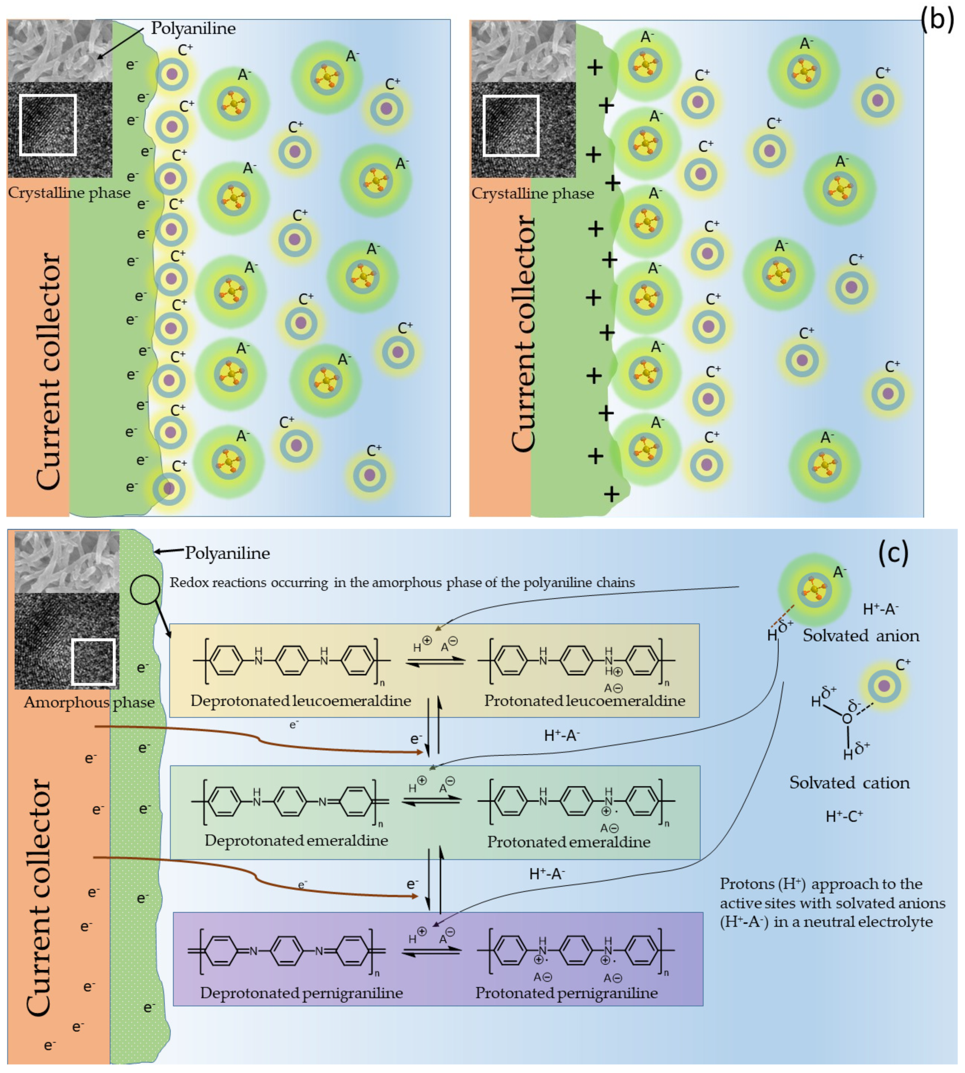
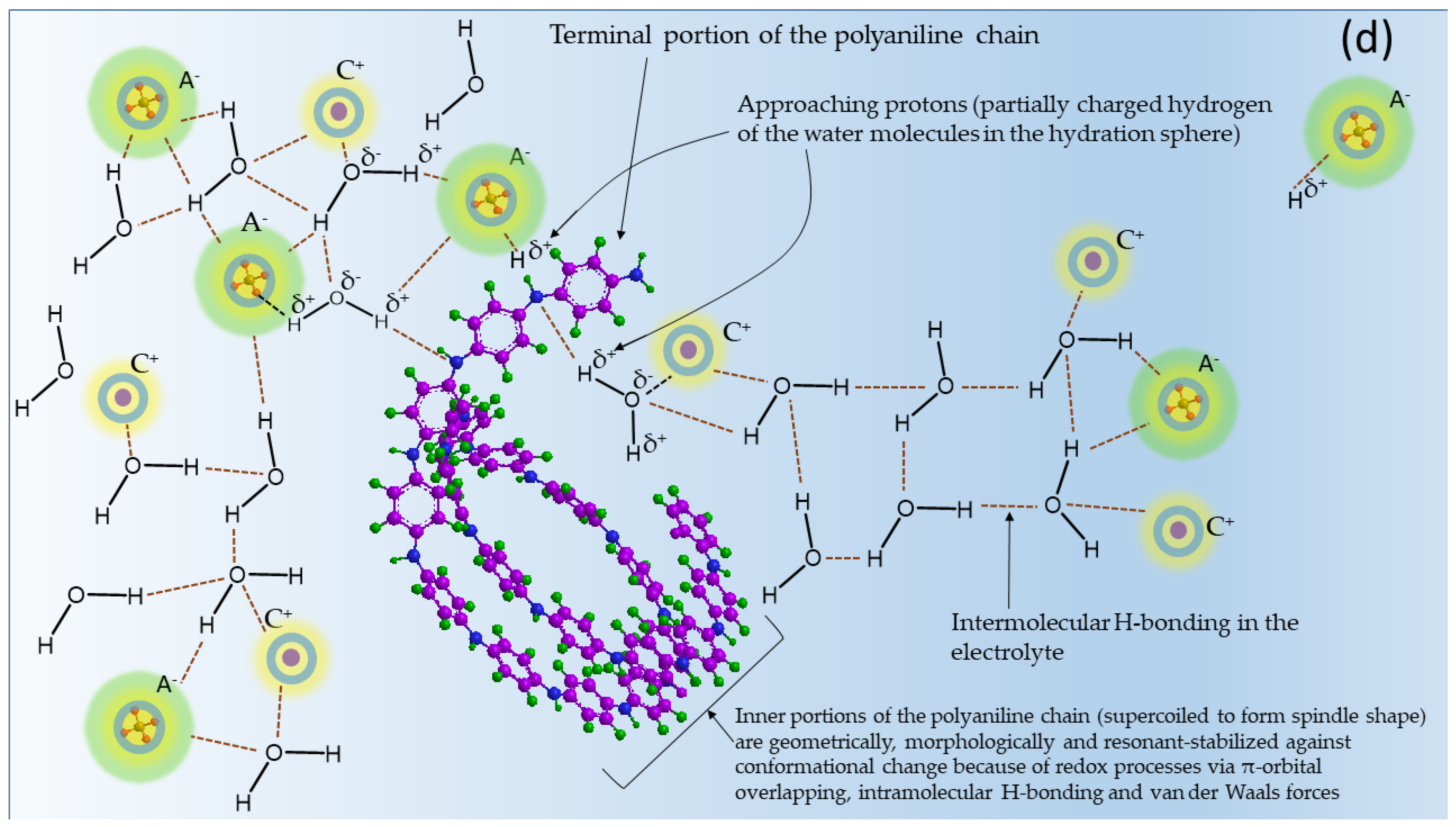
6.2. Role of Molecular Structure and Morphological Properties of Semi-Polycrystalline Polyaniline in Its Electrochemical Behavior
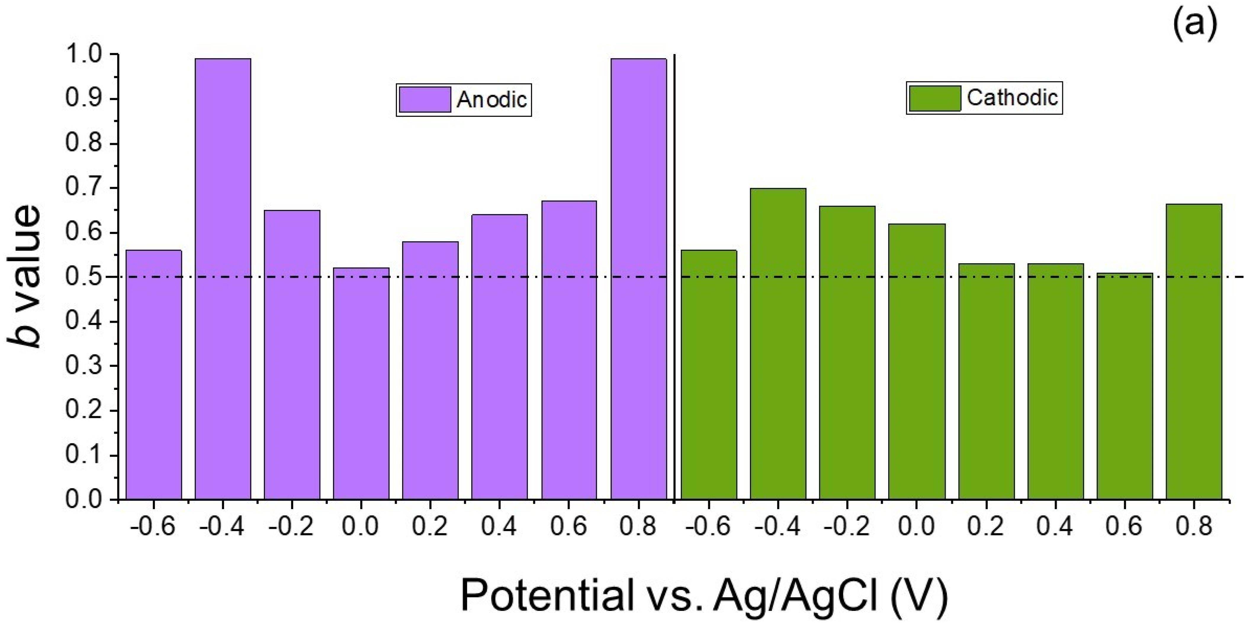
6.3. Determination of ‘b’ Values
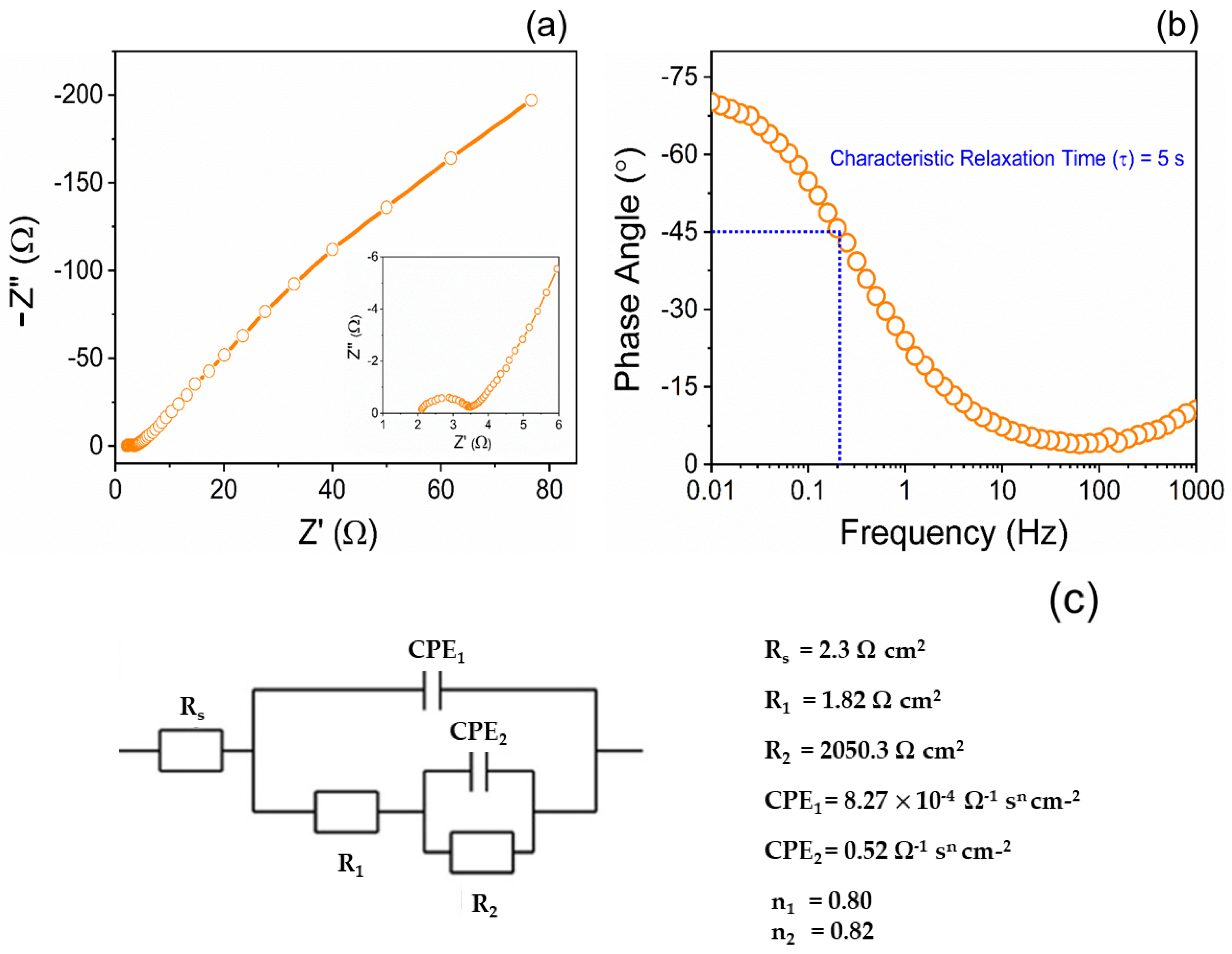
6.4. Electrochemical Impedance Spectrum Analysis
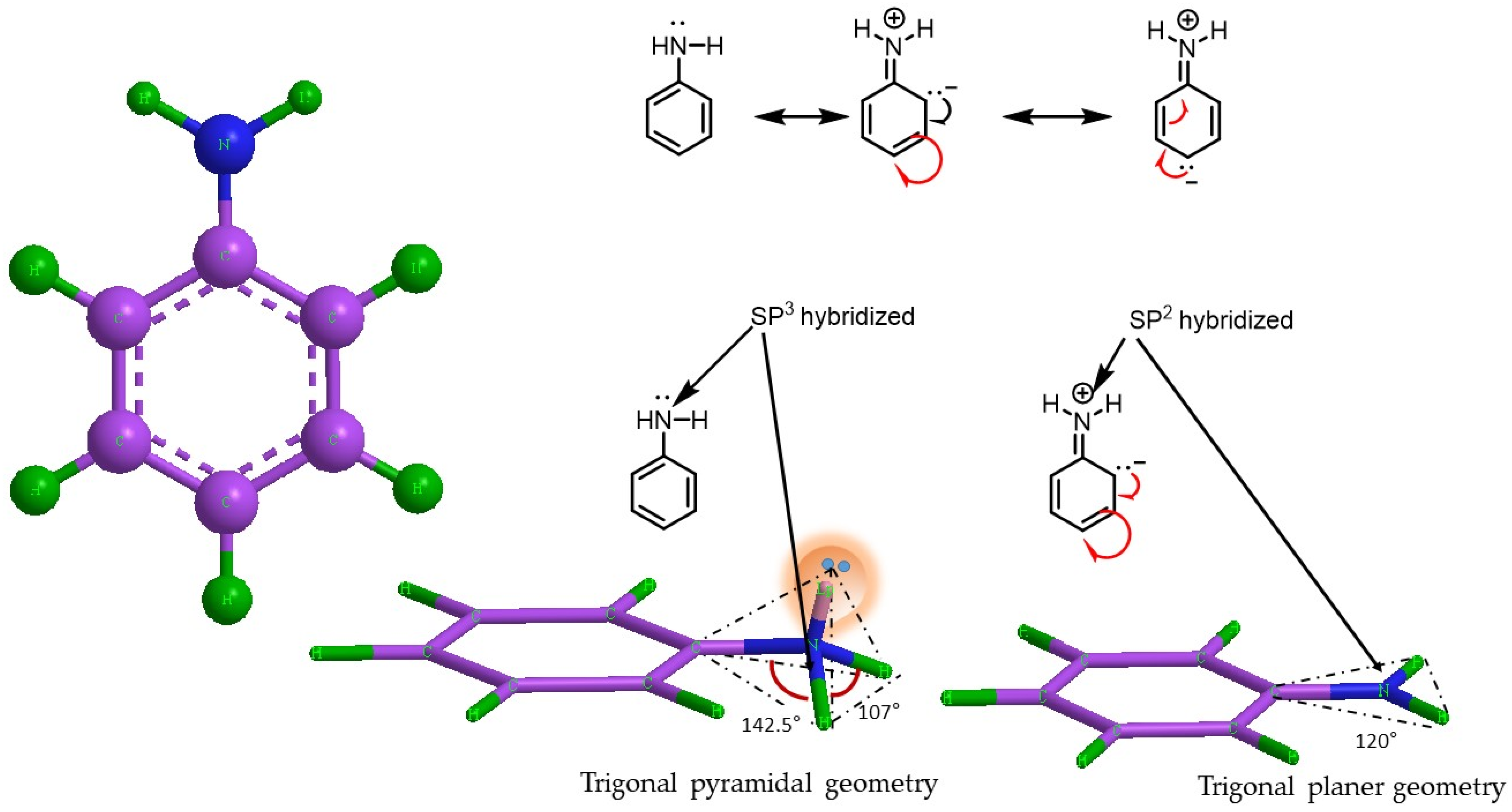
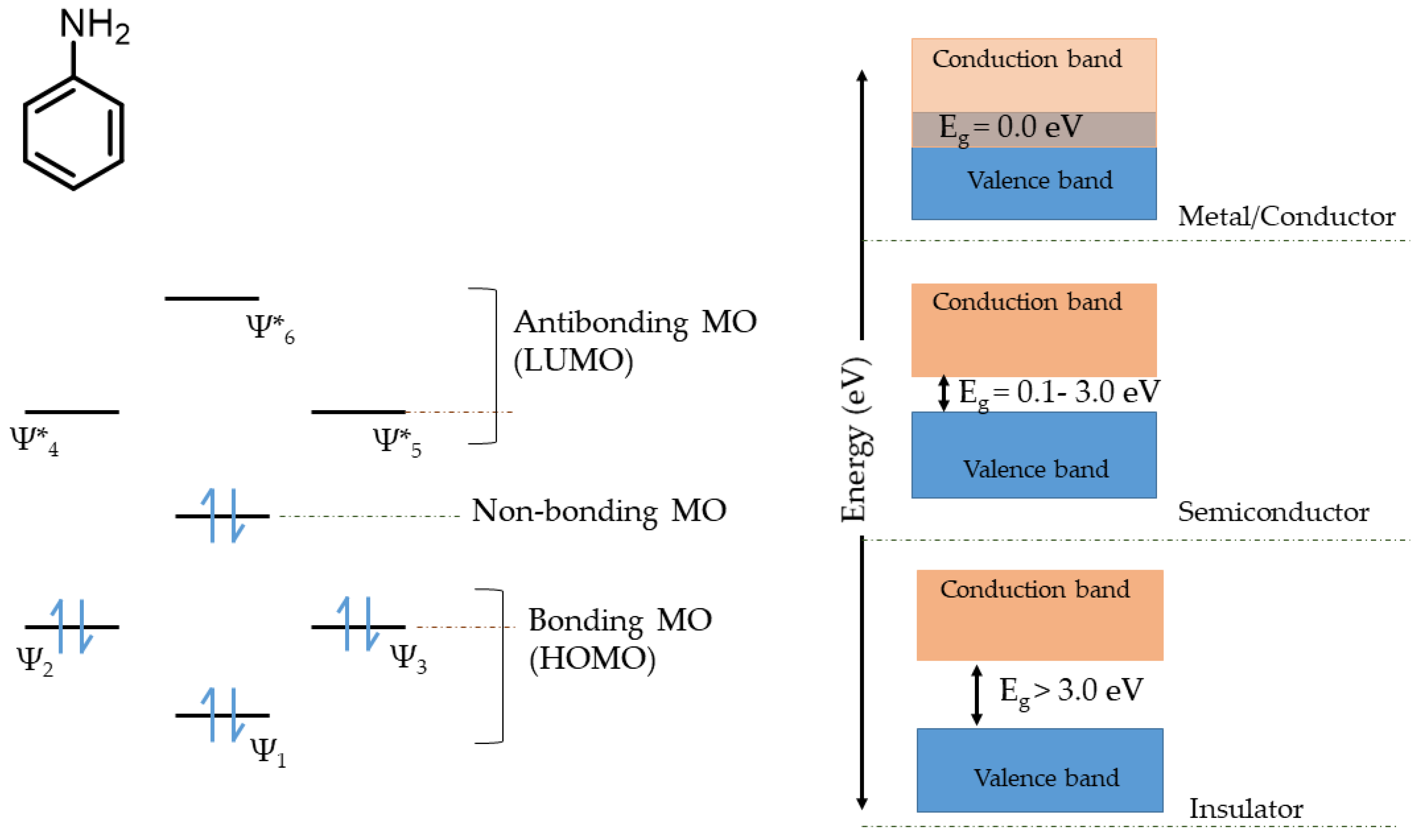
6.5. Application of Molecular Orbital Theory for Explaining the Charge Storage Mechanism Semi-Polycrystalline Polyaniline
7. Conclusions
Author Contributions
Funding
Institutional Review Board Statement
Informed Consent Statement
Data Availability Statement
Acknowledgments
Conflicts of Interest
References
- Augustyn, V.; Come, J.; Lowe, M.A.; Kim, J.W.; Taberna, P.L.; Tolbert, S.H.; Abruña, H.D.; Simon, P.; Dunn, B. High-rate electrochemical energy storage through Li+ intercalation pseudocapacitance. Nat. Mater. 2013, 12, 518–522. [Google Scholar] [CrossRef] [PubMed]
- Augustyn, V.; Simon, P.; Dunn, B. Pseudocapacitive oxide materials for high-rate electrochemical energy storage. Energy Environ. Sci. 2014, 7, 1597–1614. [Google Scholar] [CrossRef] [Green Version]
- Chodankar, N.R.; Pham, H.D.; Nanjundan, A.K.; Fernando, J.F.S.; Jayaramulu, K.; Golberg, D.; Han, Y.K.; Dubal, D.P. True Meaning of Pseudocapacitors and Their Performance Metrics: Asymmetric versus Hybrid Supercapacitors. Small 2020, 16, 2002806. [Google Scholar] [CrossRef]
- Wang, Y.; Song, Y.; Xia, Y. Electrochemical capacitors: Mechanism, materials, systems, characterization and applications. Chem. Soc. Rev. 2016, 45, 5925–5950. [Google Scholar] [CrossRef]
- Zhang, T.; Yue, H.; Gao, X.; Yao, F.; Chen, H.; Lu, X.; Wang, Y.; Guo, X. High-performance supercapacitors based on polyaniline nanowire arrays grown on three-dimensional graphene with small pore sizes. Dalton Trans. 2020, 49, 3304–3311. [Google Scholar] [CrossRef]
- Rozlívková, Z.; Trchová, M.; Exnerová, M.; Stejskal, J. The carbonization of granular polyaniline to produce nitrogen-containing carbon. Synth. Met. 2011, 161, 1122–1129. [Google Scholar] [CrossRef]
- Lapin, E.; Jureviit, I.; Maeikien, R.; Niaura, G.; Malinauskas, A. A study of electropolymerization of N,N-dimethylaniline. Synth. Met. 2010, 160, 1843–1847. [Google Scholar] [CrossRef]
- Hao, Q.; Lei, W.; Xia, X.; Yan, Z.; Yang, X.; Lu, L.; Wang, X. Exchange of counter anions in electropolymerized polyaniline films. Electrochim. Acta 2010, 55, 632–640. [Google Scholar] [CrossRef]
- Mahato, N.; Parveen, N.; Cho, M.H. Synthesis of highly crystalline polyaniline nanoparticles by simple chemical route. Mater. Lett. 2015, 161, 372–374. [Google Scholar] [CrossRef]
- Atassi, Y.; Tally, M. Electrochemical polymerization of anilinium hydrochloride. arXiv 2013, arXiv:1307.5668. [Google Scholar]
- Karunagaran, R.; Coghlan, C.; Tran, D.; Tung, T.T.; Burgun, A.; Doonan, C.; Losic, D. A facile synthesis procedure for sulfonated aniline oligomers with distinct microstructures. Materials 2018, 11, 1755. [Google Scholar] [CrossRef] [PubMed] [Green Version]
- Bhandari, S. Polyaniline; Elsevier: Amsterdam, The Netherlands, 2018; ISBN 9780128095515. [Google Scholar]
- Stejskal, J.; Trchová, M. Aniline oligomers versus polyaniline. Polym. Int. 2012, 61, 240–251. [Google Scholar] [CrossRef]
- Zhang, T.; Qi, H.; Liao, Z.; Horev, Y.D.; Panes-Ruiz, L.A.; Petkov, P.S.; Zhang, Z.; Shivhare, R.; Zhang, P.; Liu, K.; et al. Engineering crystalline quasi-two-dimensional polyaniline thin film with enhanced electrical and chemiresistive sensing performances. Nat. Commun. 2019, 10, 4225. [Google Scholar] [CrossRef] [PubMed] [Green Version]
- Wang, H.; Lin, J.; Shen, Z.X. Polyaniline (PANi) based electrode materials for energy storage and conversion. J. Sci. Adv. Mater. Devices 2016, 1, 225–255. [Google Scholar] [CrossRef] [Green Version]
- Gvozdenović, M.; Jugović, B.; Jambrec, D.; Stevanović, J.; Grgur, B. Application of polyaniline in corrosion protection of metals. Zaštita Mater. 2012, 53, 353–360. [Google Scholar]
- Ghanbari, K.; Mousavi, M.F.; Shamsipur, M. Preparation of polyaniline nanofibers and their use as a cathode of aqueous rechargeable batteries. Electrochim. Acta 2006, 52, 1514–1522. [Google Scholar] [CrossRef]
- Tomšík, E.; Dallas, P.; Šeděnková, I.; Svoboda, J.; Hrubý, M. Electrochemical deposition of highly hydrophobic perfluorinated polyaniline film for biosensor applications. RSC Adv. 2021, 11, 18852–18859. [Google Scholar] [CrossRef]
- Zhang, K.; Zhang, L.L.; Zhao, X.S.; Wu, J. Graphene/polyaniline nanofiber composites as supercapacitor electrodes. Chem. Mater. 2010, 22, 1392–1401. [Google Scholar] [CrossRef]
- Jussila, S.; Puustinen, M.; Hassinen, T.; Olkkonen, J.; Sandberg, H.G.O.; Solehmainen, K. Self-aligned patterning method of poly(aniline) for organic field-effect transistor gate electrode. Org. Electron. 2012, 13, 1308–1314. [Google Scholar] [CrossRef]
- Yang, Y.; Heeger, A.J. Polyaniline as a transparent electrode for polymer light-emitting diodes: Lower operating voltage and higher efficiency. Appl. Phys. Lett. 1994, 64, 1245–1247. [Google Scholar] [CrossRef]
- Lim, K.G.; Ahn, S.; Kim, H.; Choi, M.R.; Huh, D.H.; Lee, T.W. Self-Doped Conducting Polymer as a Hole-Extraction Layer in Organic-Inorganic Hybrid Perovskite Solar Cells. Adv. Mater. Interfaces 2016, 3, 1500678. [Google Scholar] [CrossRef]
- Mahato, N.; Cho, M.H. Graphene integrated polyaniline nanostructured composite coating for protecting steels from corrosion: Synthesis, characterization, and protection mechanism of the coating material in acidic environment. Constr. Build. Mater. 2016, 115, 618–633. [Google Scholar] [CrossRef]
- Sowmya, M.S. Multilayered electrode materials based on polyaniline/activated carbon composites for supercapacitor applications. Int. J. Hydrogen Energy 2018, 43, 4067–4080. [Google Scholar] [CrossRef]
- Ryu, K.S.; Kim, K.M.; Park, N.G.; Park, Y.J.; Chang, S.H. Symmetric redox supercapacitor with conducting polyaniline electrodes. J. Power Sources 2002, 103, 305–309. [Google Scholar] [CrossRef]
- Eftekhari, A.; Li, L.; Yang, Y. Polyaniline supercapacitors. J. Power Sources 2017, 347, 86–107. [Google Scholar] [CrossRef]
- Gu, D.; Ding, C.; Qin, Y.; Jiang, H.; Wang, L.; Shen, L. Behavior of electrical charge storage/release in polyaniline electrodes of symmetric supercapacitor. Electrochim. Acta 2017, 245, 146–155. [Google Scholar] [CrossRef]
- Majumder, M.; Thakur, A.K.; Bhushan, M.; Mohapatra, D. Polyaniline integration and interrogation on carbon nano-onions empowered supercapacitors. Electrochim. Acta 2021, 370, 137659. [Google Scholar] [CrossRef]
- Karthikeyan, K.; Amaresh, S.; Lee, S.N.; An, J.Y.; Lee, Y.S. High-power lithium-ion capacitor using LiMnBO3-nanobead anode and polyaniline-nanofiber cathode with excellent cycle life. ChemSusChem 2014, 7, 2310–2316. [Google Scholar] [CrossRef]
- Kovalenko, I.; Bucknall, D.G.; Yushin, G. Detonation nanodiamond and onion-like-carbon-embedded polyaniline for supercapacitors. Adv. Funct. Mater. 2010, 20, 3979–3986. [Google Scholar] [CrossRef]
- Soudagar, N.M.; Pandit, V.K.; Pujari, R.B.; Chorghade, K.B.; Lokhande, C.D.; Joshi, S.S. Chemically Synthesized Polyaniline Supercapacitor. Int. J. Eng. Res. Technol. 2017, 10, 587–594. [Google Scholar]
- Conway, B.E. Electrochemical Supercapacitors: Scientific Fundamentals and Technological Applications; Springer Science & Business Media: Berlin/Heidelberg, Germany, 2013. [Google Scholar]
- Conway, B.E.; Birss, V.; Wojtowicz, J. The role and utilization of pseudocapacitance for energy storage by supercapacitors. J. Power Sources 1997, 66, 1–14. [Google Scholar] [CrossRef]
- Choi, C.; Ashby, D.S.; Butts, D.M.; DeBlock, R.H.; Wei, Q.; Lau, J.; Dunn, B. Achieving high energy density and high power density with pseudocapacitive materials. Nat. Rev. Mater. 2020, 5, 5–19. [Google Scholar] [CrossRef]
- Yao, B.; Chandrasekaran, S.; Zhang, H.; Ma, A.; Kang, J.; Zhang, L.; Lu, X.; Qian, F.; Zhu, C.; Duoss, E.B.; et al. 3D-Printed Structure Boosts the Kinetics and Intrinsic Capacitance of Pseudocapacitive Graphene Aerogels. Adv. Mater. 2020, 32, e1906652. [Google Scholar] [CrossRef] [PubMed] [Green Version]
- Liu, T.; Zhou, Z.; Guo, Y.; Guo, D.; Liu, G. Block copolymer derived uniform mesopores enable ultrafast electron and ion transport at high mass loadings. Nat. Commun. 2019, 10, 675. [Google Scholar] [CrossRef] [PubMed]
- Wang, J.; Polleux, J.; Lim, J.; Dunn, B. Pseudocapacitive contributions to electrochemical energy storage in TiO2 (anatase) nanoparticles. J. Phys. Chem. C 2007, 111, 14925–14931. [Google Scholar] [CrossRef]
- Mathis, T.S.; Kurra, N.; Wang, X.; Pinto, D.; Simon, P.; Gogotsi, Y. Energy Storage Data Reporting in Perspective—Guidelines for Interpreting the Performance of Electrochemical Energy Storage Systems. Adv. Energy Mater. 2019, 9, 1902007. [Google Scholar] [CrossRef]
- Naoi, K.; Ishimoto, S.; Miyamoto, J.I.; Naoi, W. Second generation “nanohybrid supercapacitor”: Evolution of capacitive energy storage devices. Energy Environ. Sci. 2012, 5, 9363–9373. [Google Scholar] [CrossRef]
- Yu, X.; Yun, S.; Yeon, J.S.; Bhattacharya, P.; Wang, L.; Lee, S.W.; Hu, X.; Park, H.S. Emergent Pseudocapacitance of 2D Nanomaterials. Adv. Energy Mater. 2018, 8, 1702930. [Google Scholar] [CrossRef]
- Parveen, N.; Mahato, N.; Ansari, M.O.; Cho, M.H. Enhanced electrochemical behavior and hydrophobicity of crystalline polyaniline@graphene nanocomposite synthesized at elevated temperature. Compos. Part B Eng. 2016, 87, 281–290. [Google Scholar] [CrossRef]
- Sun, J.; Chen, L. Novel capacitance properties of polyaniline with branch-like chains. React. Funct. Polym. 2019, 138, 55–61. [Google Scholar] [CrossRef]
- Majumder, S.; Quang, N.D.; Kim, C.; Kim, D. Anion exchange and successive ionic layer adsorption and reaction-assisted coating of BiVO4 with Bi2S3 to produce nanostructured photoanode for enhanced photoelectrochemical water splitting. J. Colloid Interface Sci. 2021, 585, 72–84. [Google Scholar] [CrossRef] [PubMed]
- Majumder, S.; Gu, M.; Hyeon Kim, K. Facile fabrication of BiVO4/Bi2S3/NiCoO2 for significant photoelectrochemical water splitting. Appl. Surf. Sci. 2022, 574, 151562. [Google Scholar] [CrossRef]
- Shao, W.; Jamal, R.; Xu, F.; Ubul, A.; Abdiryim, T. The effect of a small amount of water on the structure and electrochemical properties of solid-state synthesized polyaniline. Materials 2012, 5, 1811–1825. [Google Scholar] [CrossRef] [Green Version]
- Kim, J.; Park, S.-J.; Kim, S. Capacitance behaviors of Polyaniline/Graphene Nanosheet Composites Prepared by Aniline Chemical Polymerization. Carbon Lett. 2013, 14, 51–54. [Google Scholar] [CrossRef] [Green Version]
- Wang, L.; Ye, Y.; Lu, X.; Wen, Z.; Li, Z.; Hou, H.; Song, Y. Hierarchical nanocomposites of polyaniline nanowire arrays on reduced graphene oxide sheets for supercapacitors. Sci. Rep. 2013, 3, 3568. [Google Scholar] [CrossRef]
- Goswami, S.; Maiti, U.N.; Maiti, S.; Nandy, S.; Mitra, M.K.; Chattopadhyay, K.K. Preparation of graphene-polyaniline composites by simple chemical procedure and its improved field emission properties. Carbon 2011, 49, 2245–2252. [Google Scholar] [CrossRef]
- Bernard, M.C.; Hugot-Le Goff, A. Raman spectroscopy for the study of polyaniline. Synth. Met. 1997, 85, 1145–1146. [Google Scholar] [CrossRef]
- Abdullah, H.S. Electrochemical polymerization and Raman study of polypyrrole and polyaniline thin films. Int. J. Phys. Sci. 2012, 7, 5468–5476. [Google Scholar] [CrossRef]
- Mažeikiene, R.; Niaura, G.; Malinauskas, A. A comparative Raman spectroelectrochemical study of selected polyaniline derivatives in a pH-neutral solution. Synth. Met. 2010, 160, 1060–1064. [Google Scholar] [CrossRef]
- Nekrasov, A.A.; Gribkova, O.L.; Iakobson, O.D.; Ardabievskii, I.N.; Ivanov, V.F.; Vannikov, A.V. Raman spectroelectrochemical study of electrodeposited polyaniline doped with polymeric sulfonic acids of different structures. Chem. Pap. 2017, 71, 449–458. [Google Scholar] [CrossRef]
- Mrlik, M.; Sedlacik, M.; Pavlinek, V.; Bober, P.; Trchová, M.; Stejskal, J.; Saha, P. Electrorheology of aniline oligomers. Colloid Polym. Sci. 2013, 291, 2079–2086. [Google Scholar] [CrossRef]
- Ciric-Marjanovic, G.; Trchová, M.; Stejskal, J. MNDO-PM3 study of the early stages of the chemical oxidative polymerization of aniline. Collect. Czechoslov. Chem. Commun. 2006, 71, 1407–1426. [Google Scholar] [CrossRef]
- Mohilner, D.M.; Adams, R.N.; Argersinger, W.J. Investigation of the Kinetics and Mechanism of the Anodic Oxidation of Aniline in Aqueous Sulfuric Acid Solution at a Platinum Electrode. J. Am. Chem. Soc. 1962, 84, 3618–3622. [Google Scholar] [CrossRef]
- Ciric-Marjanovic, G. Recent advances in polyaniline research: Polymerization mechanisms, structural aspects, properties and applications. Synth. Met. 2013, 177, 1–47. [Google Scholar] [CrossRef]
- Wawzonek, S.; McIntyre, T.W. Electrolytic Oxidation of Aromatic Amines. J. Electrochem. Soc. 1967, 114, 1025. [Google Scholar] [CrossRef]
- Wawzonek, S.; McIntyre, T.W. Electrolytic Preparation of Azobenzenes. J. Electrochem. Soc. 1972, 119, 1350. [Google Scholar] [CrossRef]
- Ohsaka, T.; Ohnuki, Y.; Oyama, N.; Katagiri, G.; Kamisako, K. IR absorption spectroscopic identification of electroactive and electroinactive polyaniline films prepared by the electrochemical polymerization of aniline. J. Electroanal. Chem. 1984, 161, 399–405. [Google Scholar] [CrossRef]
- Breitenbach, M.; Heckner, K.-H. Studies on kinetics of anodic oxidation of aniline and acetonitrile on rotating platinum electrode. J. Electroanal. Chem. Interfacial Electrochem. 1971, 29, 309–323. [Google Scholar] [CrossRef]
- Breitenbach, M.; Heckner, K.H. Untersuchungen zur Kinetik der anodischen Oxidation von Anilin in Azetonitril und Wasser an der rotierenden Scheiben-Ringelektrode. J. Electroanal. Chem. 1971, 33, 45–60. [Google Scholar] [CrossRef]
- Breitenbach, M.; Heckner, K.H. Elektrochemische untersuchungen der bildung und eigenschaften von polyanilinfilmen auf platin- und kohleelektroden. J. Electroanal. Chem. 1973, 43, 267–286. [Google Scholar] [CrossRef]
- Marjanović, B.; Juranić, I.; Ćirić-Marjanovic, G. Revised mechanism of Boyland-Sims oxidation. J. Phys. Chem. A 2011, 115, 3536–3550. [Google Scholar] [CrossRef] [PubMed]
- Sapurina, I.Y.; Shishov, M.A. Oxidative Polymerization of Aniline: Molecular Synthesis of Polyaniline and the Formation of Supramolecular Structures. In New Polymers for Special Applications; IntechOpen: Rijeka, Croatia, 2012; Available online: https://www.intechopen.com/chapters/38965 (accessed on 7 February 2022).
- Adams, R.N. Anilines in Aqueous Media1. J. Am. Chem. Soc. 1968, 3618, 6596–6599. [Google Scholar]
- Sapurina, I.; Stejskal, J. The mechanism of the oxidative polymerization of aniline and the formation of supramolecular polyaniline structures. Polym. Int. 2008, 57, 1295–1325. [Google Scholar] [CrossRef]
- Trivedi, D.C. Influence of the anion on polyaniline. J. Solid State Electrochem. 1998, 2, 85–87. [Google Scholar] [CrossRef]
- Stejskal, J.; Trchová, M.; Bober, P.; Humpolíček, P.; Kašpárková, V.; Sapurina, I.; Shishov, M.A.; Varga, M. Conducting Polymers: Polyaniline. In Encyclopedia of Polymer Science and Technology; John Wiley & Sons: Hoboken, NJ, USA, 2015; ISBN 0471440264. [Google Scholar] [CrossRef]
- Stejskal, J.; Sapurina, I.; Trchová, M.; Konyushenko, E.N. Oxidation of aniline: Polyaniline granules, nanotubes, and oligoaniline microspheres. Macromolecules 2008, 41, 3530–3536. [Google Scholar] [CrossRef]
- Tzou, K.; Gregory, R.V. Kinetic study of the chemical polymerization of aniline in aqueous solutions. Synth. Met. 1992, 47, 267–277. [Google Scholar] [CrossRef]
- Abe, M.; Ohtani, A.; Umemoto, Y.; Akizuki, S.; Ezoe, M.; Higuchi, H.; Nakamoto, K.; Okuno, A.; Noda, Y. Soluble and high molecular weight polyaniline. J. Chem. Soc. Chem. Commun. 1989, 1736–1738. [Google Scholar] [CrossRef]
- Macdiarmid, A. High Capacity Polyaniline Electrodes. U.S. Patent US4940640A, 10 July 1990. [Google Scholar]
- Wang, X.; Xu, M.; Fu, Y.; Wang, S.; Yang, T.; Jiao, K. A Highly Conductive and Hierarchical PANI Micro/nanostructure and Its Supercapacitor Application. Electrochim. Acta 2016, 222, 701–708. [Google Scholar] [CrossRef]
- Liu, T.-C.; Pell, W.G.; Conway, B.E.; Roberson, S.L. Behavior of Molybdenum Nitrides as Materials for Electrochemical Capacitors: Comparison with Ruthenium Oxide. J. Electrochem. Soc. 1998, 145, 1882–1888. [Google Scholar] [CrossRef]
- Conway, B.E.; Kannangara, D.C.W. Zinc Oxidation and Redeposition Processes in Aqueous Alkali and Carbonate Solutions. J. Electrochem. Soc. 1987, 134, 906–918. [Google Scholar] [CrossRef]
- Mahato, N.; Parveen, N.; Cho, M.H. Graphene nanodiscs from electrochemical assisted micromechanical exfoliation of graphite: Morphology and supramolecular behavior. Mater. Express 2015, 5, 471–479. [Google Scholar] [CrossRef]
- Fiordiponti, P.; Pistoia, G. An impedance study of polyaniline films in aqueous and organic solutions. Electrochim. Acta 1989, 34, 215–221. [Google Scholar] [CrossRef]
- Mahato, N.; Singh, M.M. Investigation of passive film properties and pitting resistance of AISI 316 in aqueous ethanoic acid containing chloride ions using electrochemical impedance spectroscopy(EIS). Port. Electrochim. Acta 2011, 29, 233–251. [Google Scholar] [CrossRef]
- Molapo, K.M.; Ndangili, P.M.; Ajayi, R.F.; Mbambisa, G.; Mailu, S.M.; Njomo, N.; Masikini, M.; Baker, P.; Iwuoha, E. Electronics of Conjugated Polymers (I): Polyaniline. Int. J. Electrochem. Sci. 2012, 7, 11859–11875. [Google Scholar]
- Orton, J.W. The Story of Semiconductors; Oxford University Press: Oxford, UK, 2008; ISBN 13 9780199559107. [Google Scholar] [CrossRef]
- Atkins, P.; de Paula, J. Physical Chemistry; W. H. Freeman and Co.: New York, NY, USA, 2006; ISBN 0-7167-8759-8. Available online: https://www.worldcat.org/title/atkins-physical-chemistry/oclc/47984182 (accessed on 7 February 2022).
- NobelPrize.org. The Nobel Prize in Chemistry 2000: Conducting Polymer. Available online: https://www.nobelprize.org/prizes/chemistry/2000/press-release (accessed on 7 February 2022).
- Cheng, Y.J.; Yang, S.H.; Hsu, C.S. Synthesis of conjugated polymers for organic solar cell applications. Chem. Rev. 2009, 109, 5868–5923. [Google Scholar] [CrossRef] [PubMed]


Publisher’s Note: MDPI stays neutral with regard to jurisdictional claims in published maps and institutional affiliations. |
© 2022 by the authors. Licensee MDPI, Basel, Switzerland. This article is an open access article distributed under the terms and conditions of the Creative Commons Attribution (CC BY) license (https://creativecommons.org/licenses/by/4.0/).
Share and Cite
Mahato, N.; Mohapatra, D.; Cho, M.H.; Ahn, K.S. Semi-Polycrystalline–Polyaniline Empowered Electrochemical Capacitor. Energies 2022, 15, 2001. https://doi.org/10.3390/en15062001
Mahato N, Mohapatra D, Cho MH, Ahn KS. Semi-Polycrystalline–Polyaniline Empowered Electrochemical Capacitor. Energies. 2022; 15(6):2001. https://doi.org/10.3390/en15062001
Chicago/Turabian StyleMahato, Neelima, Debananda Mohapatra, Moo Hwan Cho, and Kwang Soon Ahn. 2022. "Semi-Polycrystalline–Polyaniline Empowered Electrochemical Capacitor" Energies 15, no. 6: 2001. https://doi.org/10.3390/en15062001
APA StyleMahato, N., Mohapatra, D., Cho, M. H., & Ahn, K. S. (2022). Semi-Polycrystalline–Polyaniline Empowered Electrochemical Capacitor. Energies, 15(6), 2001. https://doi.org/10.3390/en15062001