Article

Distribution Law of In Situ Stress and Its Engineering Application in Rock Burst Control in Juye Mining Area

1
College of Energy and Mining Engineering, Shandong University of Science & Technology, Qingdao 266590, China
2
Shandong Energy Group Co., Ltd., Jinan 250014, China
3
State Key Laboratory of Mining Response and Disaster Prevention and Control in Deep Coal Mines, Huainan 232001, China
*
Authors to whom correspondence should be addressed.
Energies 2022, 15(4), 1267; https://doi.org/10.3390/en15041267
Submission received: 30 December 2021 / Revised: 31 January 2022 / Accepted: 4 February 2022 / Published: 9 February 2022
(This article belongs to the Special Issue Rock Burst Disasters in Coal Mines)

Abstract

:
This paper presents an integrated approach for mathematical statistics, theoretical analysis, and a field test to investigate the distribution law of in-situ stress and its engineering practice of rock burst control. The test site is located in the Juye mining area, Shandong Province, China. The main conclusions included: (1) There are two types of in-situ stress states in the Juye mining area, σH > σV > σh (42.42%) and σH > σh > σV (57.57%), which are mainly caused by the tectonic stress of the Heze and Fushan faults (The σH, σV, and σh is the maximum principal stress, vertical principal stress or intermediate principal stress and minimum principal stress respectively). (2) The lateral pressure coefficients KH, Kh, and Kav show a non-linear distribution with increased depth, approaching 1.32, 0.96, and 1.41, respectively. The variation range of the horizontal difference stress μd is 0.09–0.58. (3) The average value of the stress gradient is 3.05 MPa/100 m, and the main directions of the maximum horizontal principal stress are northeast–southwest, and northwest–southeast. (4) A new combined supporting strategy, incorporating optimization of roadway layout, anti-impact support system design, and local reasonable pressure relief, was proposed for the rock burst control, and its validity was verified via field monitoring. All these design principles and support strategies for the rock burst control presented in this study can potentially be applied to other similar projects.

1. Introduction

1.1. Research Background

In-situ stress is the fundamental force that causes the deformation and failure of the surrounding rock in underground caverns, civil buildings, slopes, and other geotechnical engineering structures [1,2]. With the increase of the energy demand in China, coal mining has entered a state of deep mining [3]. Due to the higher mining intensity and the more complex distribution of in-situ stress, a large deformation of the deep roadway, damage of the support structure, and even rock burst and other disasters occur frequently [4,5]. A basic consensus has been reached in the mining industry that the prevention and control of disaster accidents related to underground coal mining should start with in-situ stress measurement and analysis [6,7].
To date, a number of studies have been conducted to investigate in-situ stress measurement methods and equipment, field measurement, and its distribution law in China. For example, Cai et al. [8] proposed a device for in-situ stress measurement based on complete temperature compensation, and further put forward the calculation method for in-situ stress. Kang et al. [9] presented a small-aperture hydraulic-fracturing in-situ stress measurement method and applied it in Luan, Jincheng, Fenxi, and other mining areas in China. Wang et al. [10] performed field monitoring to investigate the in-situ stress distribution law of the Ping-ding-shan mining area. Chen et al. [11] elaborated on the mechanism of rock burst in a deep roadway and developed a series of roadway anti-impact bolts, hydraulic supports, etc. Jiang et al. [12] established a variety of rock burst models in coal mines and summarized the characteristics, occurrence mechanism, and prevention technologies of rock burst disasters in China. All these studies have improved our understanding of the in-situ stress measurement and its relationships with the rock burst control.
It is well known that the distribution of in-situ stress is closely related to the geological structure, and exhibited evident regional distribution characteristics [13,14]. The Juye mining area, located southwest of Shandong Province, is currently the most important coal-resource-producing area in Shandong Province. However, faults and folds are seriously developed, and the seismic activity is strong in this area. All these complex geological structures contribute to higher regional stress accumulation levels. Consequently, many rock burst accidents occurred in coal mines of the Juye mining area, resulting in a considerable number of casualties, extra labour, financial resources, and time loss. However, due to the lack of measured data, the relevant studies on the characteristics of the in-situ stress field and its correlation with rock burst disaster are very limited.
First of all, the roadway layout of most mines in the Juye mining area did not consider the influence of in-situ stress at the beginning. Secondly, with the increase of mining depth, some mines that did not have rock burst before also began to have rock burst. In addition, the current rock burst prevention and control system is not perfect, and some mines in the Juye mining area have an obvious lack of impact resistance. All this is due to our lack of a clear understanding of the in-situ stress field in the Juye mining area and a complete set of impact support systems. Therefore, we must systematically study the in-situ stress field in the Juye mining area. As stated at the beginning of the article, in-situ stress is the basic stress of all engineering disasters. Of course, this also includes rock burst disaster. By studying the stress field environment, we can preliminarily determine the basic conditions of rock burst, so as to prevent rock burst.

1.2. Article Structure

The objective of this study is to develop a better understanding of the distribution characteristics of in-situ stress in the Juye mining area, and its application in rock burst control. The organization chart of this paper is as shown in Figure 1.
This paper is organized as follows: the geological structure characteristics evolution characteristics in the Juye mining area were first presented in Section 1. In Section 2, the type and direction of the in-situ stress field were revealed based on the collected in-situ stress data, and the variation law of principal stress, the lateral pressure coefficient, as well as the horizontal difference stress with depth, are discussed in this paper. In Section 3, the design principles of the roadway layout and the anti-impact support were proposed in the Juye mining area, its validity was verified by a field application. The results presented in this paper have important theoretical and practical implications for the exploitation of coal resources, the construction of roadway engineering structures, and the prevention and control of rock burst disasters in the Juye mining area.

2. Engineering Background

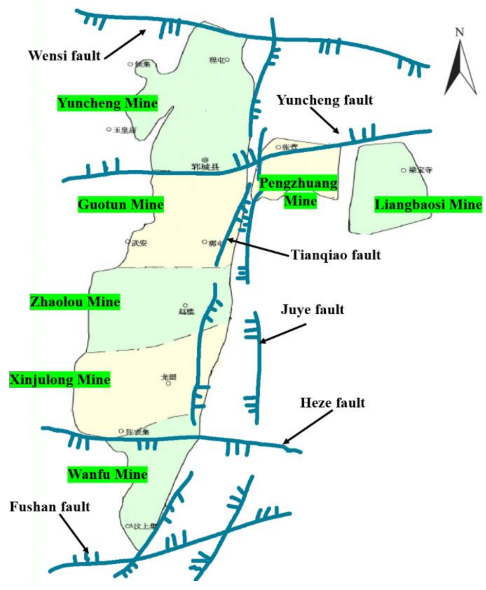
2.1. Geological Conditions

The Juye mining area includes Juye, Jinxiang, Liangbaosi, and other places, with a total area of 2600 km2 and a coal-bearing area of 1210 km2. The total proven coal reserves are 5.571 billion tons. Seven pairs of coal mines are planned and constructed in the Juye mining area, which are the Yuncheng, Guotun, Zhaolou, Xinjulong, Wanfu, Liangbaosi, and Pengzhuang coal mines. The annual coal production is 18 million tons, which effectively solves the energy supply problem in Shandong Province and even East China (Figure 2).
The strata in the Juye mining area are well distributed from Archean to Cenozoic. From top to bottom, the strata are Quaternary, Neogene, Permian, Carboniferous, and Ordovician. The Quaternary and Neogene strata are mainly composed of clay and sandy clay, with an average deposition thickness of more than 500 m. The Carboniferous Permian stratum is mainly composed of mudstone, sandstone, and coal, which is the coal-bearing stratum in this area. The Ordovician stratum is mainly composed of limestone, dolomite, and marlstone. 3# coal seam is the main mining coal seam in this area, with an average thickness of 6.6 m and a buried depth of 700–1300 m.
The Juye mining area is located in the North China plate and the Luxi uplift. It is a fault depression basin with a large number of folds and fault zones. Its main tectonics and its location are shown in Figure 2. The strike of the coalfield is generally close to the north–south (NS) direction, and the coal seam is mainly controlled by the fault zone. The fault zone is distributed in a grid shape, mainly including the Wensi, Yuncheng, Heze, Fushan, Tianqiao, and Juye faults. The basic characteristics are listed in Table 1. There is a large number of east–west (EW) trending faults, and most of them are bulges and depressions. The near north–south (NS) direction fault is mainly controlled by the Tianqiao and Liaokao faults. In addition, a large number of north–east (NE) to near north–east (NE) and EW folds are developed in the region, which makes the overall tectonic stress field more complex.

2.2. Evolution Law of the Geological Structure in the Juye Mining Area

The Juye mining area is located to the east of the North China plate, bounded by the LiaoKao fault in the west, the Tan Lu fault in the East, the Qi Guang fault in the north, and the Hefei Basin in the Mesozoic-Cenozoic stratum in the south. In geological history, the Juye mining area has experienced three major tectonic movements: the Indosinian movement in the Triassic stratum, the middle Yanshanian movement in the Mesozoic stratum, and the late Yanshanian movement.
The Indonesian movement formed the strata of the whole North China coal accumulation basin before the Triassic fold uplift and fault movement. The collision of the north and south continental blocks triggered the Paleozoic strata fold and fault movement, forming the east-west (EW)fold and fault. The tectonic stress field in this period was mainly in the south–north (SN) direction, which is the first stage of the development of the tectonic stress field.
In the middle Yanshan period, the north–west (NW) compression weakened with the mantle plastic flow. The lateral tension of the mantle plastic flow and the compression force of the plate edge in the north–west (NW) direction jointly controlled the development of normal faults. The south–north (SN) and east-west (EW) normal faults control the occurrence of coal measure strata in the Juye mining area. In this period, the north–west (NW) tectonic force was the strongest, and the direction of the tectonic stress field was northwest–southeast (NW–SE), which is the second stage of the development of the tectonic force field.
In the late Yanshan period, the mantle stress is replaced by the plate extrusion pressure. The deviation of rock strata was caused by compression action, and thus an arc structure was gradually formed. Then, the stratum was squeezed and uplifted by many different directions of tension and torsion. The direction of the tectonic stress field in this period was mainly north–east (N–E) direction. This is the third stage of the development of the tectonic stress field.
From the above analysis, it can be concluded that the geological structure and in-situ stress field in the Juye mining area are in a state of constant change. From the SN direction in the first tectonic movement to the NW direction in the second tectonic movement and finally to the NNE direction in the third tectonic movement.

3. Distribution Characteristics of the In-Situ Stress in the Juye Mining Area

3.1. Data Sources

The “recommended method for determining rock stress” was promulgated by the committee on test methods of the international society for rock mechanics in 1987. They confirmed the following four measurement methods as recommended methods: flat jack method, hydraulic fracturing method, USBM borehole diameter deformation gauge method, and CSIRO hollow inclusion strain gauge method. At present, the hollow inclusion stress measurement method is the only method that can measure three-dimensional in-situ stress state. It can eliminate the error caused by temperature, so we choose the hollow inclusion stress relief method for in-situ stress measurement.
An in-situ stress test was conducted in the Guotun and Pengzhuang coal mines from 2018 to 2020, thus acquiring 12 groups of in-situ stress measurement data. In addition, the in-situ stress data of the other five coal mines were collected from the published literatures in recent years. Then, all data sources were optimized by setting a 95% confidence level. Finally, a total of 66 groups in-situ stress data were selected and used for the analysis.
Some of the selected in-situ stress measurement results are listed in Table 2. Thereinto, H is the buried depth of the measurement point, σv is the vertical principal stress, σH is the maximum horizontal principal stress, and σh is the minimum horizontal principal stress. The overall distribution of the maximum principal stress is displayed in Figure 3.

3.2. Analysis of the In-Situ Stress Data

3.2.1. Types of In-Situ Stress Field

Table 3 listed the distribution of the in-situ stress field types with depth changes. It can be seen clearly that there are two types of in-situ stress fields in the Juye mining area, σH > σV > σh (42.42%) and σH > σh > σV (57.57%). The two types of in-situ stress field changes with the buried depth. In the depth range of less than 900 m, the σH > σv > σh-type stress state is dominant. Within the more than 900 m depth, the σH > σh > σv-type stress field is dominant. Furthermore, with the increasing of the depth, the vertical principal stress gradually transits from the middle principal stress to the minimum principal stress.
Combined with the relative position of each mine (Figure 2) and its geological structure characteristics, the σH > σv > σh-type stress field was found to mainly appear north of the Heze fault, but not south of it. The σH > σh > σv-type is mainly in the south of the Heze fault. This may be attributed to the tectonic stress caused by the EW-trending Heze and Fushan faults in the south of the mining area.

3.2.2. Variation of Principal Stress with Depth

The maximum, minimum, and vertical principal stresses and the corresponding buried depth of each measurement point were plotted in Figure 4. The least-square method was used for linear regression fitting. The fitting results are as follows:
σH = 0.04548H − 4.7344 (R2 = 0.89382)
σh = 0.04245H − 16.428 (R2 = 0.88381)
σv = 0.01377H + 8.4259 (R2 = 0.90271)
where H is the depth (m), and R2 is the correlation coefficient.
From Equations (1)–(3), it can be concluded that a good fitting effect was obtained by the three main stress fitting equations with the correlation coefficient R2 of greater than 0.88. It can be also seen in Figure 4 that the principal stress value increases approximately linearly with the depth, and the maximum principal stress is slightly discrete. This may be caused by the differences in the geological structure and rock stratum characteristics in different degrees of the local range.
The in-situ stress fitting results of the Juye mining area were compared with those of the surrounding areas, as shown in Table 4. (All measured data in Table 4 are obtained by hollow inclusion stress relief method). It can be inferred that the variation trend between the Juye mining area and the surrounding areas shows a good agreement on the whole. However, the σH and σh stress gradient changes are relatively large, and the σv is relatively small. This difference also exhibits the complexity and evident regionality of the distribution characteristics of the in-situ stress field in this mining area.

3.2.3. Variation of the Lateral Pressure Coefficient with Depth

The lateral pressure coefficient is an important characterization of the in-situ stress state. In this paper, the ratios of σH to σv, σh to σv, and σ(H + h)/2 to σv are denoted as KH, Kh, and Kav. They were used to analyze the variation law of the in-situ stress state with depth. The curve function K = a/H + b was used for regression fitting, and the fitting results are as follows:
KH = 61.78/H + 1.32
Kh = 87.56/H + 0.96
Kav = 117.41/H + 1.41
Figure 5a–c shows the fitting curves of three lateral pressure coefficients varying with depth. It can be concluded that the distribution of the KH data is relatively discrete, ranging from 1.02 to 3.22, with an average of 1.74. The distribution of Kh and Kav shows a good regularity. The Kh value is 0.36–2.03 with an average of 1.05, and the Kav is 0.74–2.63 with an average of 1.39. In general, with increased depth, the values of the three lateral pressure coefficients have a decreasing trend. It can also be inferred that KH, Kh, and Kav approach 1.32, 0.96, and 1.41, respectively, indicating that the horizontal tectonic stress is dominated in the Juye mining area.

3.2.4. Variation Law of Horizontal Difference Stress with Depth

The horizontal difference stress μd = (σ13)/(σ1 + σ3) is an important parameter for characterizing the state of crustal failure. In this paper, the non-linear curve μd = a/H + b was used to fit the law of μd with depth. The fitting curve is shown in Figure 6. The fitting results are as follows:
μd = 12.23/H + 0.21
It can be seen from Figure 6 that the distribution of the μd is relatively centralized, reflecting a good fitting effect. The range of μd is 0.09–0.58, with an average of 0.26, and 73% of the stresses were 0.20–0.30. With increased depth, there is a trend approaching 0.2. Related studies have shown that the formation tends to slip shear failure when the μd value exceeds 0.5–0.7. The μd of the Juye mining area is within the 0.09–0.58, and most of the stresses are less than 0.5. Thus, it can be inferred that slip failure is not likely to occur in the Juye mining area under the current stress state.

3.2.5. In-Situ Stress Level and Stress Gradient in the Mining Area

The number of measurement points of each stress level is shown in Figure 7. According to the in-situ stress level criteria [17,18], there are 50 points with super-high stress (more than 30 MPa), accounting for 75.75%; 14 points with high stress (18–30 MPa), accounting for 21.21%; 2 points with medium stress (10–18 MPa), accounting for 3.03%.
The stress gradient of each mine is listed in Table 5. It can be seen that the overall stress gradient value of the mining area is large, and the dispersion is high. Particularly, the stress gradient of the Wanfu and Guotun coal mines exceeds 4.0 MPa/100 m, which is caused by the large buried depth and the tectonic stress fields. Therefore, more attention should be paid to engineering problems caused by high in-situ stress in the mining process of deep coal resources in the Juye mining area.

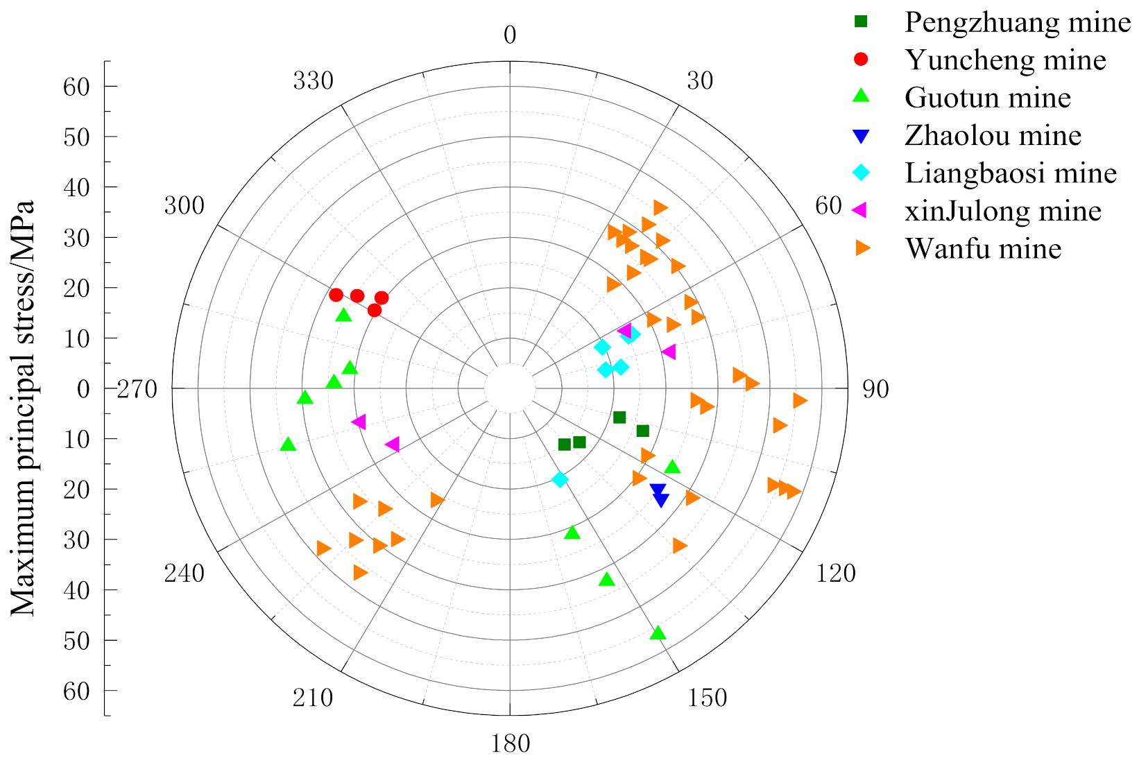
3.2.6. Direction Characteristics of the Maximum Horizontal Principal Stress

Figure 8 is a rose diagram of the dominant direction of the maximum horizontal principal stress in the Juye mining area. Statistics show that there are 43 measurement points in the northeast–southwest (NE–SW) direction, accounting for 65.15%, and 23 measurement points in the northwest–southeast (NW–SE) direction, accounting for 34.84%. The dominant direction of the maximum horizontal principal stress in the Juye mining area is northeast–southwest (NE–SW), and northwest–southeast (NW–SE) also accounts for a large proportion. This is consistent with the direction of the whole Shandong area [19].
The maximum horizontal principal stresses in the different mines have various degrees of difference, see Figure 9. In particular, the direction of the maximum horizontal principal stress in the Liangbaosi coal mine presents a certain degree discrete, which is less consistent with the whole Juye mining area. On the whole, the two maximum principal stress directions northeast–southwest (NE–SW), and northwest–southeast (NW–SE) alternate from north to south. The development of composite folds and faults leads to the strata movement from the northwest (NW) to the northeast (NE) and east–west (E–W), thus resulting in the deflection of the principal stress direction.

4. Engineering Practice of Rock Burst Control in the Juye Mining Area

4.1. Analysis on the Influencing Factors of Rock Burst

It has been proved that the near-field static load is the internal cause of rock burst, while the far-field dynamic load is the external cause [20,21]. When the static load level is high, a small dynamic load can also lead to rock burst. The Juye mining area is characterized by a super-large depth and a complex geological structure, which make the stratum itself contain ultra-high static stress with variable direction (as shown in Figure 7, Figure 8 and Figure 9). Additionally, the stress redistribution process induced by coal mining activities further improves the near-field static load level of the surrounding rock [22]. Consequently, the probability of rock burst is very high due to the accumulated extremely high static stress. In other words, the high static stress is the fundamental driving force of rock burst in the Juye mining area. Therefore, taking reasonable measures to weaken the high static stress of the rock mass surrounding the mining space is the key to preventing rock burst.

4.2. Strategy for the Rock Burst Control

In this paper, a new combined supporting strategy, incorporating optimization of roadway layout, anti-impact support system design, and local reasonable pressure relief, was proposed for the rock burst control. The detailed technology parameters should be determined based on the existing economic and technical conditions, relevant theories, and engineering practice of various mines in the Juye mining area.
(1)
Optimization of roadway layout
The fundamental way of preventing rock burst is optimizing the excavation position and time [23,24]. The following are the specific measures. First, roadways should be excavated along the direction of the maximum principal stress or at an acute angle with it as far as possible. Taking the Zhaolou coal mine as an example, roadways should be arranged along the EW direction as far as possible. Second, for the gob-side entry arranged in a single coal seam, it should be excavated along the edge of the stable goaf with a 3–5 m small coal pillar or no-coal-pillar. The roadways should be performed 1.5 ~ 2 years after the mining of the adjacent panel. Thus, the gob-side entry can be performed in a low-stress environment. Third, the 3# main coal seam in this area is developed in layers with 20–110 m intervals. Under this condition, the upper layer with a smaller thickness should be exploited first to optimize the stress environment of the lower-layered roadway. Fourth, the roadway layout should avoid large geological structures (fault, fold, collapse column) as far as possible.
(2)
Anti-impact support scheme design
The anti-impact support system is mainly composed of three parts, of which the first part is high-strength anchor bolt, anchor cable, and anchor mesh. The second part is the hydraulic support, which can protect the working face and construction personnel. The third part is the advanced unit support, which can resist the advanced stress brought by the mining of the working face.
Improving the anti-impact performance of the support system is another important measure to rock burst control [25,26,27]. Based on the theory of collaborative bearing, an anti-impact support system consisting of one-stage high-strength anchor cables, two-stage advanced unit supports, and three-stage hydraulic supports is formed [28,29]. Thereinto, the anchor-bearing structure is the last line of prevention and control of rock burst. It is necessary to scientifically select bolts, cables, and surface protection components to improve its overall impact resistance [30,31].
The details are as follows. First, a high-elongation bolt with a yield strength greater than 500 MPa is selected for the anchor, and a T-shaped steel strip with a high bearing capacity, and a large-area thickened butterfly tray are used at the same time. A steel strand with a 21.8 mm diameter is used as an anchor cable, which is used with a large tray and a thick steel strip. Meanwhile, a double-bubble yielding ring is used to improve the elongation of the anchor cable. The roadway surface is reinforced by a high-strength anti-impact woven mesh. Second, a walking hydraulic support is used for support within 50 m ahead of the working face, and a unit support is used for support within 50–120 m. Compared with the conventional single hydraulic support, advanced unit support and hydraulic support are characterized by a large support area and a high bearing capacity. When a rock burst occurs, they can maintain the roadway space and reduce the casualties.
(3)
Local pressure relief measures
During panel retreating, local high stress concentrations occurred frequently in the two ribs of the roadway, which may result in rock burst accidents. Therefore, it is necessary to take the combination pressure relief measures of large-diameter drilling and blasting to prevent rock bursts from occurring [32,33]. Under normal conditions, large-diameter drilling with reasonable drilling spacing, diameter, and depth design is used to relieve pressure. In the case of stress, concentration cannot be relieved by large-diameter drilling, blasting measures should be performed to release the high stress.

4.3. Engineering Practice

This paper provides an illustrative, detailed algorithm on how to implement the suggested method to control the rockburst based on measured in-situ stresses. As shown in Figure 10, first conduct in-situ stress measurement, and then obtain stress conditions according to the measurement results. The roadway layout is guided according to the stress direction, and the roadway support strength is designed according to the stress value. Combined with geological, engineering, and technical conditions, a rock burst prevention and control system is formed. Finally, the engineering effect is analyzed. When the stability does not meet the requirements, the roadway support design is carried out again until the stability requirements are met. So far, the final permanent support system is formed. The following will be explained in combination with specific examples.

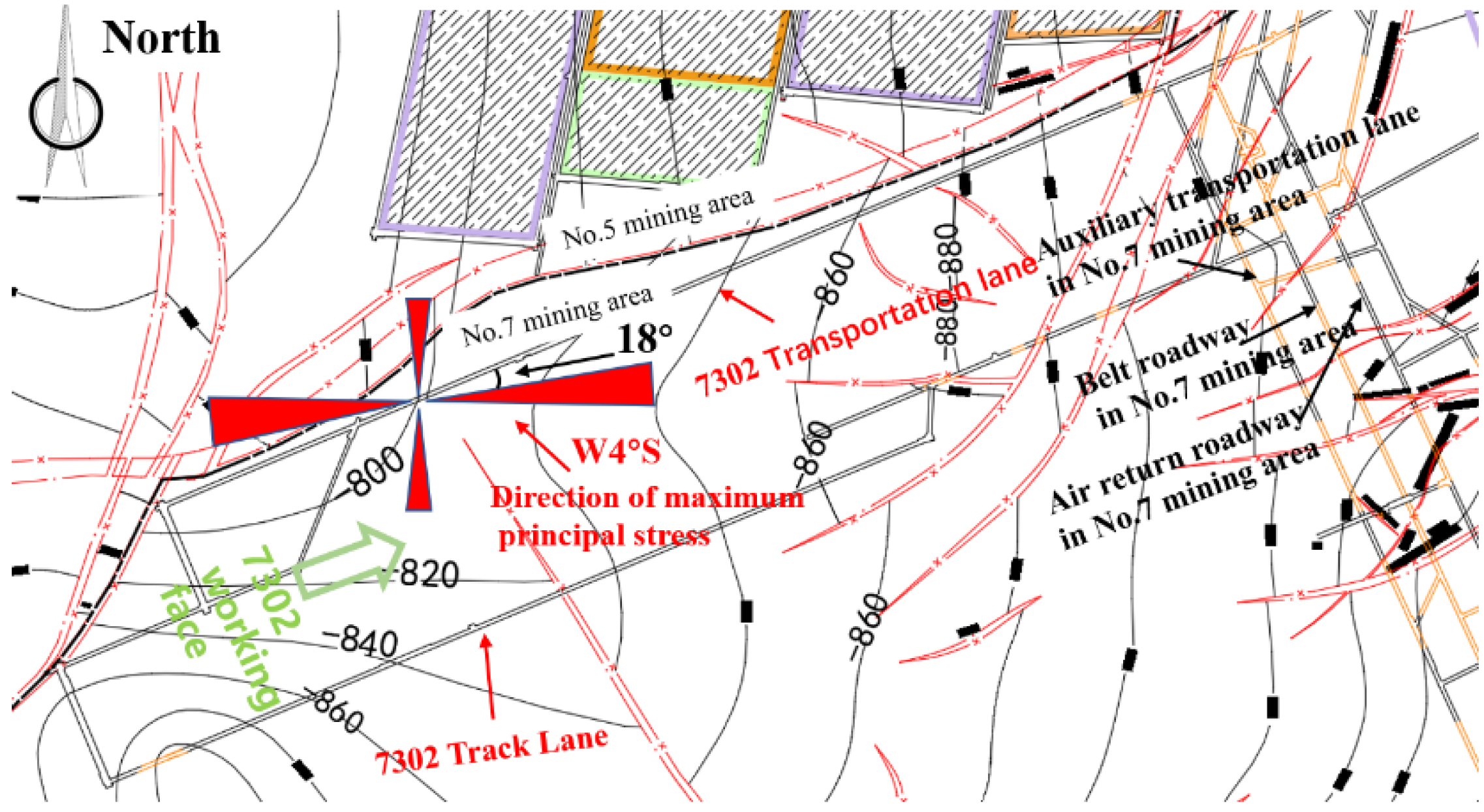
4.3.1. Engineering Geology of the Test Site

The test site is located in the 7302 working face of the Zhaolou coal mine, with an average depth of 860 m. The north of the working face is the goaf of the no. 5 mining district and the large fault. The average thickness of the coal seam is 6.0 m. The roof is the sandstone with an average thickness of 19.48 m, while the floor is the sandstone with an average thickness of 9.1 m.
According to the in-situ stress measurement results of the Zhaolou coal mine, the average maximum principal stress is 36.2 MPa, the average vertical stress is 27.61 MPa, and the minimum principal stress is 22.12 MPa. The maximum horizontal principal stress is in the W4°S direction (near east–west direction).

4.3.2. Roadway Layout and Support Scheme Design

Considering the specific engineering geological conditions and construction conditions of the 7302 working face, an optimization design scheme is implemented. The angle between the direction of excavation and the maximum principal stress is set to 18 degrees (W22°S). The roadway is driven along the coal seam floor, with a trapezoidal section shape, which is 4.0 m high, 4.8 m wide at the top, 5.8 m wide at the bottom, and the area is 22.5 m2. The specific layout of the roadway is shown in Figure 11.
The anti-impact support system of the one-stage high-strength anchor cable, two-stage advanced unit support, and three-stage hydraulic support scheme are adopted. The specific support parameters are as follows.
  • Six high-strength threaded steel bolts with a 22 mm diameter, a 2400 mm length, and 500 MPa tensile strength were used in the roof. The bolts were installed with a spacing of 850 mm × 800 mm. The bolts are connected to each other by a T-shaped steel belt with a 10 mm thickness, 140 mm width, and 4800 mm length. In addition, three high-strength anchor cables with a 22 mm diameter and a 6.2 m length are used in the roadway roof. The row spacing of the anchor cables is 1600 mm, and they are connected by a three-hole 29U steel bar with a 4400 mm length. An FZJ-R1/2 double-bubble yielding ring is installed at the tail of each anchor cable.
  • Six left-handed full-threaded bolts with 20 mm in diameter and 2500 mm in length were installed with a spacing of 850 mm × 800 mm in the two ribs of the roadway. Two 1900-mm-long narrow steel strips were used for bolts connection. Three high-strength anchor cables with a 22 mm diameter and a 6200 mm length were added to the non-mining side. The spacing of the anchor cables is 1200 mm × 1600 mm. The 18-channel steel anchor cable beam with a size of 3000 × 1600 × 1200 mm is used for cables connection. The specific support scheme is shown in Figure 12.
  • Five groups of ZT115200/25/45 hydraulic supports were used within 50 m ahead of the working face, and ZJC3078/32/45D unit supports were used within 50–120 m. The overall length of the advance support should not be less than 120 m.
  • Large-diameter boreholes were used for pressure relief in the two sides of the roadway in the medium-strong impact risk area. The hole diameter is 150 mm, depth is 20 m, and the hole spacing is 1.5–2 m and 2–2.5 m, respectively; and the height between the boreholes and the floor is 1.2–1.5 m. The boreholes are perpendicular to the coal wall. The layout of the boreholes is shown in Figure 13.

4.3.3. Analysis of the Engineering Effect

After the use of the new roadway layout and support scheme, the deformation of two sides and the roof were within the control range. The average roof subsidence was 200 mm, the two ribs’ convergence was 360 mm, and there was no floor heave and an obvious dynamic behavior event.
During the panel retreat period, the deformation of the roadway increased slightly, and the overall deformation is always at a low level. The roadway could meet the requirements of the ventilation and normal mining of the working face. The field support effect is shown in Figure 14.

5. Conclusions

This paper mainly focuses on the distribution law of in-situ stress field in the Juye mining area, and the specific control measures for rock burst prevention are presented. The main conclusions are as follows:
(1)
The main tectonic evolution law of the in-situ stress field is from the north–south (NS) direction to the northwest–southeast (NW–SE) direction and finally to the northeast–southwest (NE–SW) direction in the Juye mining area.
(2)
The two types of the in-situ stress field in the Juye mining area are σH > σv > σh and σH > σh > σv. The average stress gradient is 3.05 MPa/100 m. The dominant direction of the maximum horizontal principal stress is northeast–southwest (NE–SW), but northwest–southeast (NW–SE) also accounts for a large proportion. The discreteness of the in-situ stress types and directions is mainly caused by a large number of fault zones in the Juye mining area and their complex tectonic movements.
(3)
The lateral pressure coefficient KH, Kh, and Kav approach 1.32, 0.96, and 1.41, respectively. The range of μd is 0.09–0.58, thus, it can be inferred that slip failure is not likely to occur in the Juye mining area under the current stress state.
(4)
The superpositions of high static and mining stresses lead to the rock burst disasters in the Juye mining area, and the high static stress is the fundamental driving force of rock burst. The key to preventing rock burst is to weaken the high stress in the surrounding rock.
(5)
A new combined supporting strategy, incorporating optimization of roadway layout, anti-impact support system design, and local reasonable pressure relief, was proposed for the rock burst control. The anti-impact support system includes a one-stage high-strength anchor cable, two-stage advanced unit support, and three-stage hydraulic support.

Author Contributions

The author G.Z. sorted out the ideas of the full paper and completed the writing of the abstract and introduction. Y.L. and X.M. has completed the analysis of the law of in-situ stress distribution and the engineering background. G.T., L.W. and C.Z. wrote the Engineering practice of rock burst control in the Juye mining area. H.Z. and Z.Q. carried out the field test. Data curation and analysis, H.G. All authors have read and agreed to the published version of the manuscript.

Funding

This study was supported by the National Natural Science Foundation of China (No.51904164), Opening Foundation of State Key Laboratory of Mining Response and Disaster Prevention and Control in Deep Coal Mines (SKLMRDPC20KF05).

Institutional Review Board Statement

Not applicable.

Informed Consent Statement

Not applicable.

Data Availability Statement

The data used to support the findings of this study are included in the article.

Conflicts of Interest

The authors declare that they have no conflict of interest.

References

  1. Bai, T.; Yang, H.; Chen, X.-B.; Zhang, S.-C.; Jin, Y.-S. In-situ monitoring and reliability analysis of an embankment slope with soil variability. Geomech. Eng. 2020, 3, 261–273. [Google Scholar]
  2. Bednarek, L.; Majcherczyk, T. An analysis of rock mass characteristics which influence the choice of support. Geomech. Eng. 2020, 21, 371–377. [Google Scholar]
  3. Bandyopadhyay, K.; Mallik, J.; Ghosh, T. Dependence of fluid flow on cleat aperture distribution and aperture–length scaling: A case study from Gondwana coal seams of Raniganj Formation, Eastern India. Int. J. Coal. Sci. Technol. 2020, 7, 133–146. [Google Scholar] [CrossRef] [Green Version]
  4. Xing, P.-J.; Mclennan, J.; Moore, J. In-situ stress measurements at the utah frontier observatory for research in geothermal energy (forge) site. Energies 2020, 13, 5842. [Google Scholar] [CrossRef]
  5. Pan, Y.-S.; Dai, L.-P.; Li, G.-Z.; Li, Z.-H. Theoretical research and application of rock burst roadway support in mine. J. China Coal Soc. 2021, 46, 112–122. [Google Scholar]
  6. Brooke-Barnett, S.; Flottmann, T.; Paul, P.K.; Busetti, S.; Hennings, P.; Reid, R.; Rosenbaum, G. Influence of basement structures on in situ stresses over the Surat Basin, southeast Queensland. J. Geophys. Res. Solid Earth 2015, 120, 4946–4965. [Google Scholar] [CrossRef]
  7. Das, A.J.; Mandal, P.K.; Paul, P.S.; Sinha, R.K. Generalised analytical models for the strength of the Inclined as well as the flat coal pillars using rock mass failure criterion. Rock Mech. Rock Eng. 2019, 52, 3921–3946. [Google Scholar] [CrossRef]
  8. Cai, M.-F.; Guo, Q.-F.; Li, Y.; Du, Z.-F.; Liu, J.-H. Geostress measurement and its application in pingmei mine. Chin. J. Eng. 2013, 11, 1399–1406. [Google Scholar]
  9. Kang, H.-P.; Jiang, T.-M.; Zhang, X.; Yan, L.-X. Research and application of in-situ stress field in Jincheng mining area. Chin. J. Rock Mech. Eng. 2009, 28, 1–8. [Google Scholar]
  10. Wang, Y.-C.; Jing, H.-W.; Chen, K.-F.; Wei, L.-Y. Research on in-situ stress distribution and spatial zoning in Pingdingshan mining area. Chin. J. Rock Mech. Eng. 2014, 33, 2620–2627. [Google Scholar]
  11. Chen, J.-H.; Liu, P.; Zhao, H.-B.; Zhang, C.; Zhang, J.-W. Analytical studying the axial performance of fully encapsulated rock bolts. Eng. Fail. Anal. 2021, 128, 1–16. [Google Scholar] [CrossRef]
  12. Salmachi, A.; Rajabi, M.; Wainman, C.; Mackie, S.; Mccabe, P.; Camac, B.; Clarkson, C. History, geology, in situ stress pattern, gas content and permeability of coal seam gas basins in australia: A review. Energies 2021, 14, 2651. [Google Scholar] [CrossRef]
  13. Sun, Y.; Zuo, J.; Karakus, M.; Liu, L.; Zhou, H.; Yu, M. A New Theoretical Method to Predict Strata Movement and Surface Subsidence Due to Inclined Coal Seam Mining. Rock Mech. Rock Eng. 2021, 54, 2723–2740. [Google Scholar] [CrossRef]
  14. Shen, W.-L.; Shi, G.-C.; Wang, Y.-G.; Bai, J.-B.; Zhang, R.-F.; Wang, X.-Y. Tomography of the dynamic stress coefficient for stress wave prediction in sedimentary rock layer under the mining additional stress. Int. J. Min. Sci. Technol. 2021, 31, 653–663. [Google Scholar] [CrossRef]
  15. Li, P.; Guo, Q.-F.; Liu, H.-T.; Jiang, X.-Q. Analysis on the characteristics of current in-situ stress field and stress accumulation level in Shandong Province. Chin. J. Rock Mech. Eng. 2017, 36, 2220–2231. [Google Scholar]
  16. Huang, L.-Y.; Yang, S.-X.; Cui, X.-F.; Chen, Q.-C.; Yao, R. Analysis of characteristics of measured stress and stability of faults in North China. Chin. J. Geophys. 2013, 34, 204–213. [Google Scholar]
  17. Cheng, Y.M.; Wang, J.A.; Xie, G.X.; Wei, W.B. Three-dimensional analysis of coal barrier pillars in tailgate area adjacent to the fully mechanized top caving mining face. Int. J. Rock Mech. Min. Sci. 2010, 47, 1372–1383. [Google Scholar] [CrossRef]
  18. Han, H.-X.; Yin, S.-D. Determination of in-situ stress and geomechanical properties from borehole deformation. Energies 2018, 11, 131. [Google Scholar] [CrossRef] [Green Version]
  19. Yang, J.-C.; Liu, K.-W.; Li, X.-D.; Liu, Z.-X. Stress initialization methods for dynamic numerical simulation of rock mass with high in-situ stress. J. Cent. South Univ. 2020, 27, 3149–3162. [Google Scholar] [CrossRef]
  20. Han, Z.-H.; Zhou, J.; Zhang, L.Q. Influence of grain size heterogeneity and in-situ stress on the hydraulic fracturing process by pfc2d modeling. Energies 2018, 11, 1413. [Google Scholar] [CrossRef] [Green Version]
  21. Pan, J.-F.; Ning, Y.; Lan, H.; Du, T.-T.; Peng, Y.-W. Starting theory of rock burst in coal mining. Chin. J. Rock Mech. Eng. 2012, 31, 586–596. [Google Scholar]
  22. Jepson, G.; King, R.C.; Holford, S.; Bailey, A.H.E.; Hand, M. In situ stress and natural fractures in the Carnarvon Basin, North West Shelf, Australia. Explor. Geophys. 2019, 50, 514–531. [Google Scholar] [CrossRef]
  23. Chen, S.J.; Ren, M.Z.; Wang, F.; Yin, D.W.; Chen, D.H. Mechanical properties and failure mechanisms of sandstone with pyrite concretions under uniaxial compression. Geomech. Eng. 2020, 22, 385–396. [Google Scholar]
  24. Zhang, D.-Q.; Yang, P.; Wu, J.-Y.; Zhao, J.; Chen, Y.-A. Preparation of defect free ceramic/Ti composite membranes by surface modification and in situ oxidation. J. Cent. South Univ. 2019, 26, 3295–3304. [Google Scholar] [CrossRef]
  25. Yi, K.; Liu, Z.-H.; Lu, Z.G.; Zhang, J.-W.; Dong, S.-Y. Effect of axial in-situ stress in deep tunnel analysis considering strain softening and dilatancy. Energies 2020, 13, 1502. [Google Scholar] [CrossRef] [Green Version]
  26. Shabanimashcool, M.; Li, C.C. Analytical approaches for studying the stability of laminated roof strata. Int. J. Rock Mech. Min. Sci. 2015, 79, 99–108. [Google Scholar] [CrossRef]
  27. Mohammed, M.M.; Roslan, H.; Firas, S. Assessment of rapid impact compaction in ground improvement from in-situ testing. J. Cent. South Univ. 2013, 20, 786–790. [Google Scholar] [CrossRef]
  28. Zhang, G.-C.; Zang, C.-W.; Chen, M.; Tao, G.-Z.; Li, Y.; Hou, W.-H.; Weng, H.-Z.; Zhao, D.-S. Ground response of entries driven adjacent to a retreating longwall panel. Int. J. Rock Mech. Min. Sci. 2021, 138, 10–17. [Google Scholar]
  29. Zhang, G.-C.; He, F.-L.; Jia, H.-G.; Lai, Y.-H. Analysis of gateroad stability in relation to yield pillar size: A case study. Rock Mech. Rock Eng. 2017, 50, 1263–1278. [Google Scholar] [CrossRef]
  30. Zhang, G.-C.; Wen, Z.-J.; Liang, S.-J.; Tan, Y.-L.; Tian, L.; Zhao, Y.-Q.; Zhao, D.-S. Ground Response of a Gob-side Entry in a Longwall Panel Extracting 17 m-Thick Coal Seam: A Case Study. Rock Mech. Rock Eng. 2020, 53, 497–516. [Google Scholar] [CrossRef]
  31. Chen, J.-H.; Li, D.-Q. Numerical simulation of fully encapsulated rock bolts with a tri-linear constitutive relation. Tunn. Undergr. Space Technol. 2022, 120, 1–13. [Google Scholar] [CrossRef]
  32. Li, X.-P.; Zhang, G.-C.; Tao, G.-Z.; Wang, C.; Cao, H.-X.; Zhao, X.-P.; Yan, X.-Y.; Shen, S.-B.; Zhou, G.-L. Ground Behaviors Analysis of a Stope Covered by the Thin Bedrock and Large-Thick Alluvium: A Case Study. Shock. Vib. 2022, 21, 1–14. [Google Scholar] [CrossRef]
  33. Smith, J.-A. Analysis of the influence of groundwater and the stress regime on bolt behaviour in underground coal mines. Int. J. Coal. Sci. Technol. 2019, 6, 286–300. [Google Scholar] [CrossRef] [Green Version]
Figure 1. Article organization chart.
Energies 15 01267 g001
Figure 2. Structural distribution of the Juye mining area.
Energies 15 01267 g002
Figure 3. General distribution of principal stress.
Energies 15 01267 g003
Figure 4. Fitting curve of principal stress with depth.
Energies 15 01267 g004
Figure 5. Fitting curves of the lateral pressure coefficients changing with the depth. (a). Ratio of horizontal stress to vertical stress; (b) Ratio of minimum principal stress to vertical stress; (c) Ratio of average horizontal stress to vertical stress.
Energies 15 01267 g005
Figure 6. Variation of μd with burial depth.
Energies 15 01267 g006
Figure 7. Stress distribution grade of each measurement point.
Energies 15 01267 g007
Figure 8. Rose diagram of the maximum principal stress in the mining area.
Energies 15 01267 g008
Figure 9. Directional distribution of the maximum horizontal principal stress.
Energies 15 01267 g009
Figure 10. Algorithm flow chart.
Energies 15 01267 g010
Figure 11. General layout of the roadway at the working face 7302.
Energies 15 01267 g011
Figure 12. Support scheme of the working face 7302.
Energies 15 01267 g012
Figure 13. Schematic diagram of the layout of the drilling hole.
Energies 15 01267 g013
Figure 14. Support effect of the roadway surrounding rock.
Energies 15 01267 g014
Table 1. Characteristics of the main fault structures in the mining area.
Name of Fault ZoneStrikeDipDip Angle
Wensi fault90–130°Southwest70–80°
Yuncheng fault80–90°North70–80°
Heze fault90–110°South70–80°
Fushan fault70–90°South45–80°
Juye fault180°West85°
Tianqiao fault185–230°Southeast70°
Table 2. In-situ stress measurement results of some measurement points.
NumberMeasurement Point PositionH/mσH(MPa)σv(MPa)σh(MPa)Direction of Maximum Horizontal StressSchematic Diagram of Principal Stress Direction
1Yuncheng Mine 1300 track lane829.530.5123.1317.86273° Energies 15 01267 i001
2Yuncheng Mine 800 m preparation roadway842.434.5925.3219.88275° Energies 15 01267 i002
3Pengzhuang Mine 1309 track lane721.517.1311.849.73128.64° Energies 15 01267 i003
4Pengzhuang Mine West Wing roadway537.015.3312.897.57136.86° Energies 15 01267 i004
5Zhaolou Mine No. IV crossing point86034.7223.2729.98263º Energies 15 01267 i005
6Zhaolou Mine No. XI crossing point86036.4024.5021.57255º Energies 15 01267 i006
7Liangbaosi Mine North Wing track roadway70820.4918.059.33330° Energies 15 01267 i007
8Liangbaosi Mine 3300 track land82625.0421.4712.74300° Energies 15 01267 i008
9Xinjulong Mine 1301N track lane83025.1018.9015.60154º Energies 15 01267 i009
10Xinjulong Mine north track lane82531.718.814.9125° Energies 15 01267 i010
11Xinjulong Mine transportation lane90029.520.712.6127° Energies 15 01267 i011
12Xinjulong Mine in the No. 1 mining area75024.916.919.8152° Energies 15 01267 i012
13Guotun Mine 1304 track lane855.644.1624.3616.87300° Energies 15 01267 i013
14Guotun Mine 1301 track lane842.231.3320.6317.13294° Energies 15 01267 i014
15Wanfu Coal Mine #1891.630.5518.6420.40155.3° Energies 15 01267 i015
16Wanfu Coal Mine #2102436.4322.0524.50153.4° Energies 15 01267 i016
Table 3. Distribution of in-situ stress field types with depth.
Depth (m)Number of Different Types of Data
σH > σv > σhσH > σh > σvTotal
500–700101
700–900261440
900–110012223
>1100022
Total283866
Table 4. Comparison of the principal stress variations with depth of the Juye mining area and other mining areas.
σHσhσvRegionSource
0.04548H − 4.730.04245H − 16.43σ0.01377H + 8.431Juye mining areaThis article
0.0242H + 9.42690.0180H + 3.83020.0258H + 0.5626Shandong ProvinceLi et al. [15]
0.0233H + 4.6650.0162H + 2.100-North ChinaHuang et al. [16]
Table 5. Stress gradient values of each mine.
Mine NameAverage Sounding (m)Average Maximum Principal Stress (MPa)Stress Gradient
(MPa/100 m)
Yuncheng Mine842.133.43.96
Pengzhuang Mine692.020.32.93
Liangbaosi Mine771.121.92.83
Zhaolou Mine860.035.64.13
Xinjulong Mine826.327.83.37
Wanfu Mine970.940.34.15
Guotun Mine803.338.74.81
Publisher’s Note: MDPI stays neutral with regard to jurisdictional claims in published maps and institutional affiliations.

