
Stability and Cementation of the Surrounding Rock in Roof-Cutting and Pressure-Relief Entry under Mining Influence


Abstract
:1. Introduction
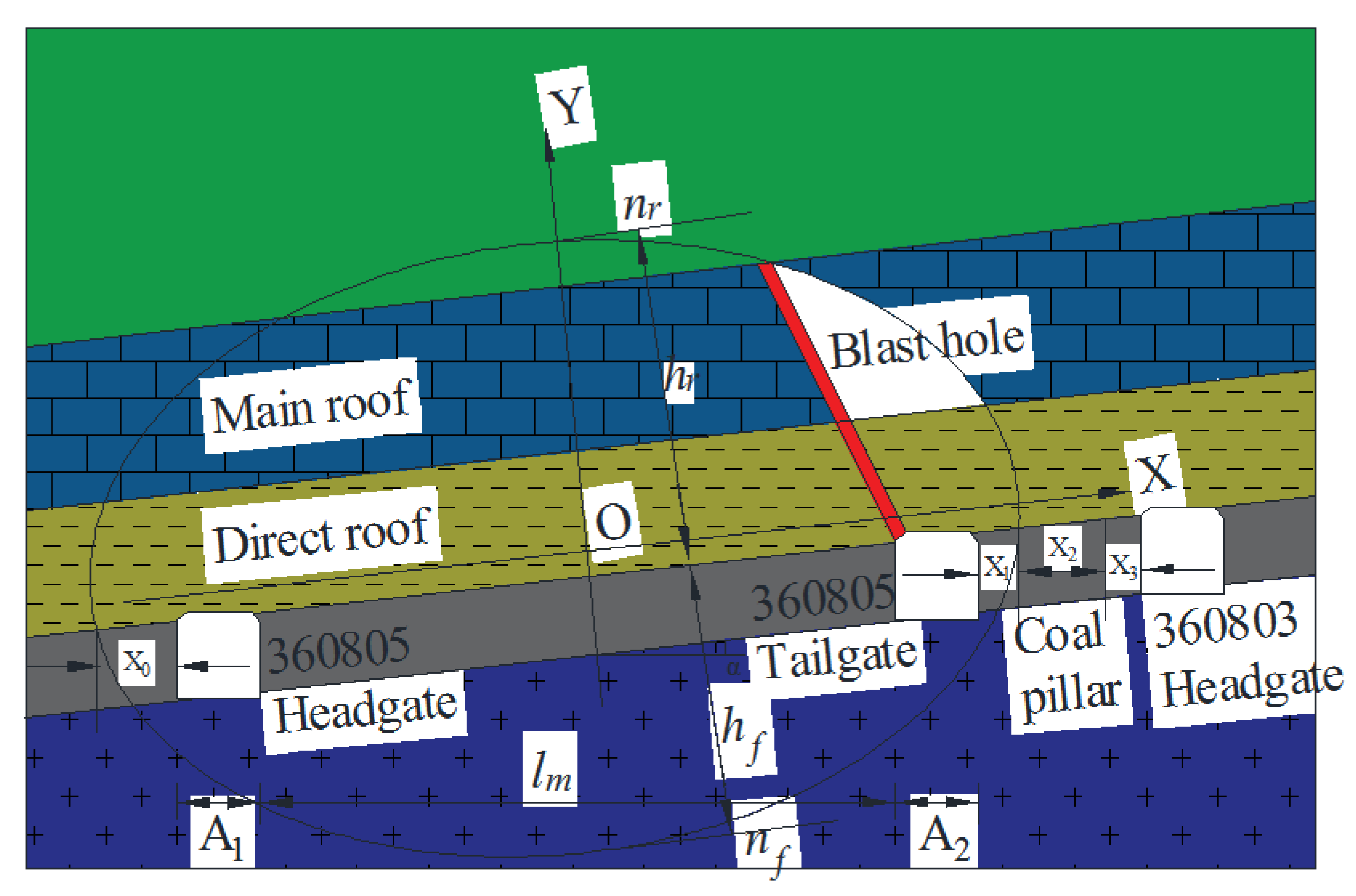
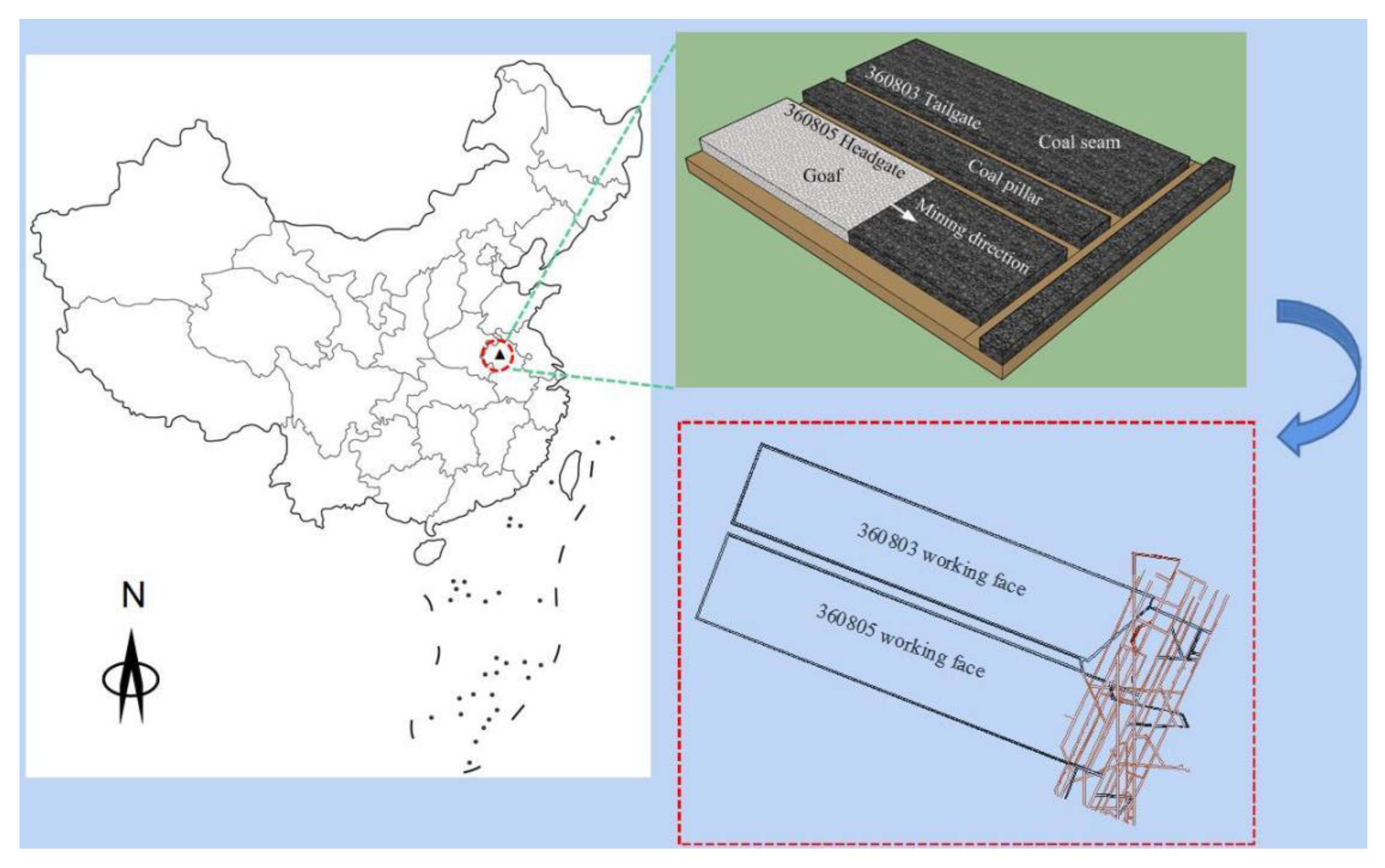
2. Project Profile
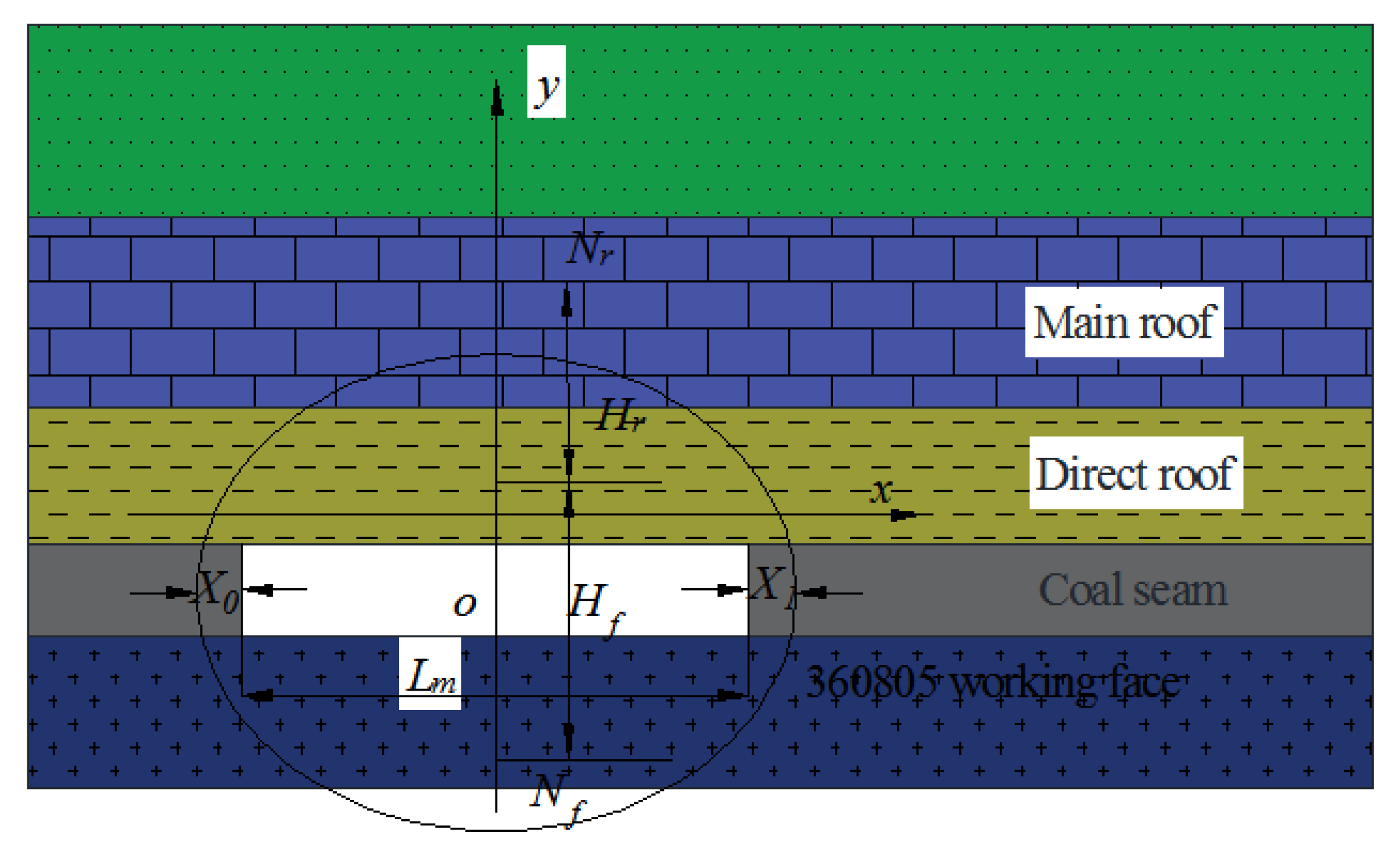
3. Construction of Mechanical Model
4. Advanced Roof-Cutting Pressure-Relief Parameters of 360,805 Working Face and Process Study
4.1. Explosive Type
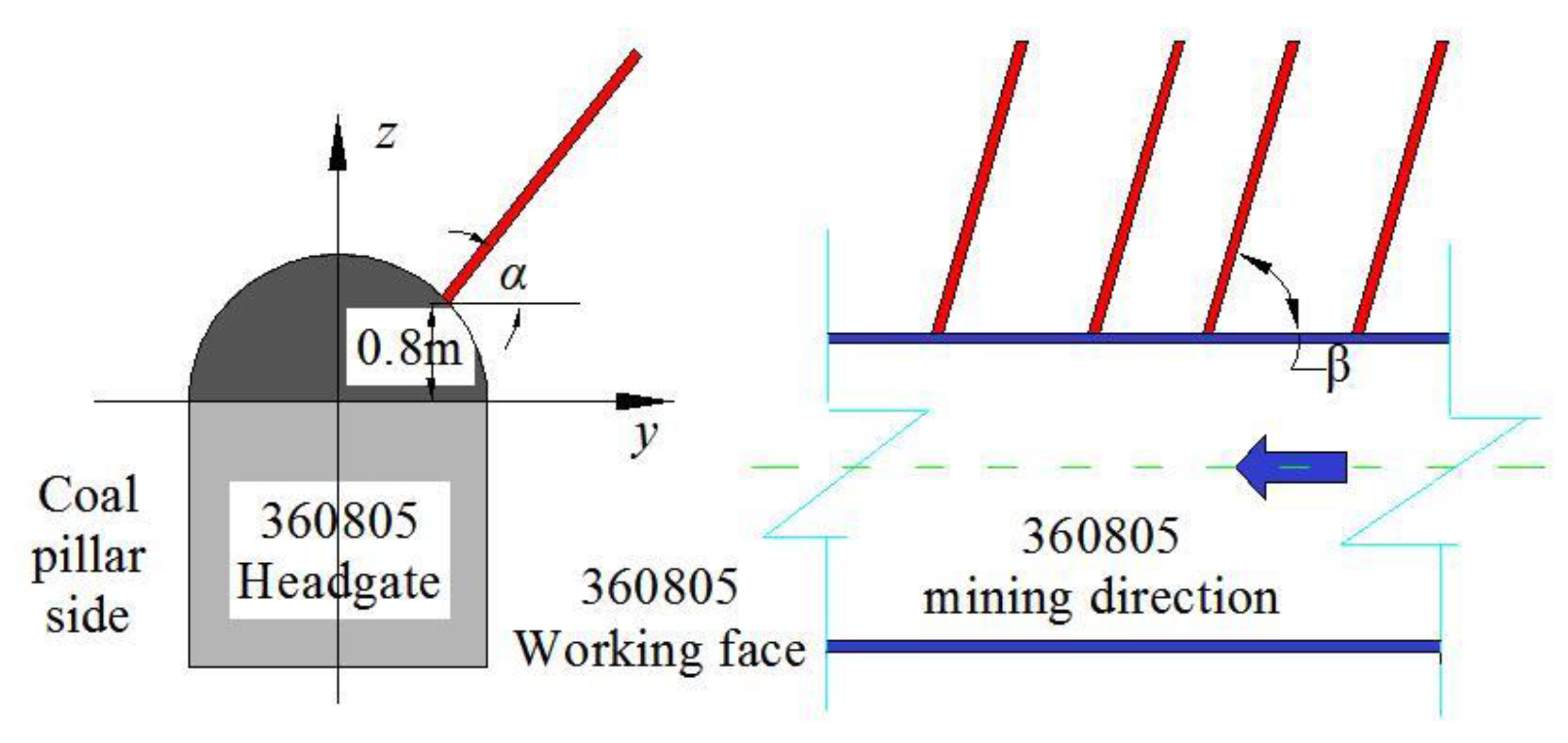
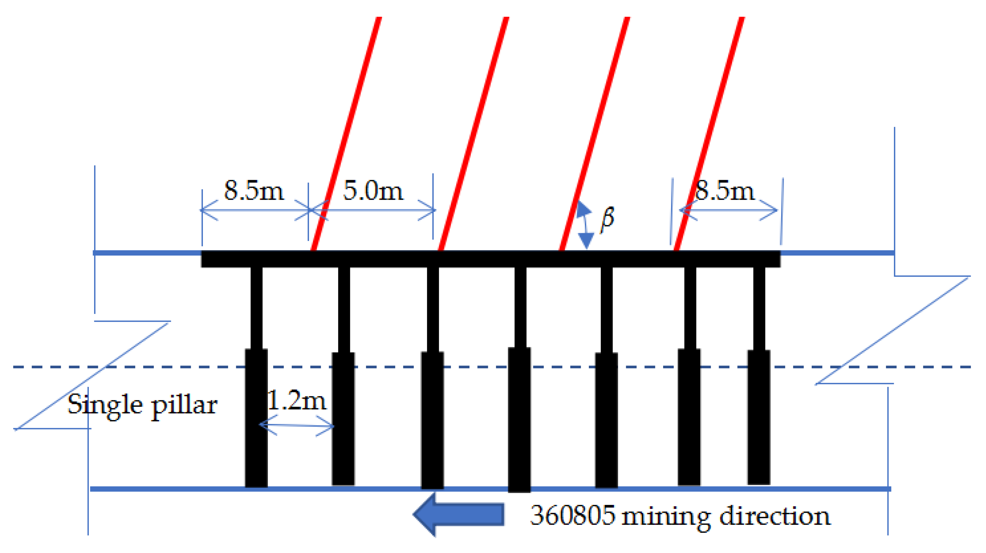
4.2. Determination of Array Pitch of Boreholes
4.2.1. Radius of Crushed Zone
4.2.2. Radius of Fractured Zone
- (1)
- Calculation according to the action of blasting stress wave.
- (2)
- Calculation according to the action of quasistatic pressure generated by blasting gas.
4.2.3. Radius of Vibration Zone
4.3. Roof-Cutting Height
4.3.1. Stratum Judgment of Hard Roof Strata
4.3.2. Strata Load at Hard Roof Strata
4.3.3. Breaking Span of Hard Roof Strata and Their Fracturing Order
4.3.4. Number of Roof Strata Sequences (Ycm) Filling the Goaf
4.4. Depth of Blast Hole Pl
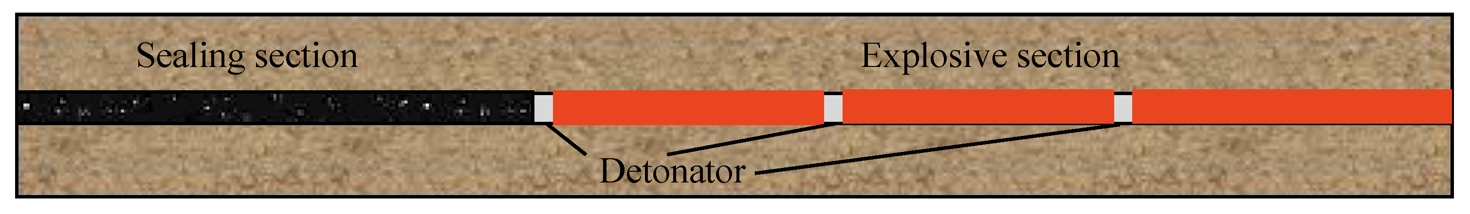
4.5. Charging Structure
5. Stability Judgment of Roadway-Supporting Coal Pillars in Roof-Cutting Pressure-Relief Roadway under Mining Influence
5.1. Strata Load Borne by Coal Pillars
5.2. Number of Sequences (Yjx) at Roof Caving Limit Stratum
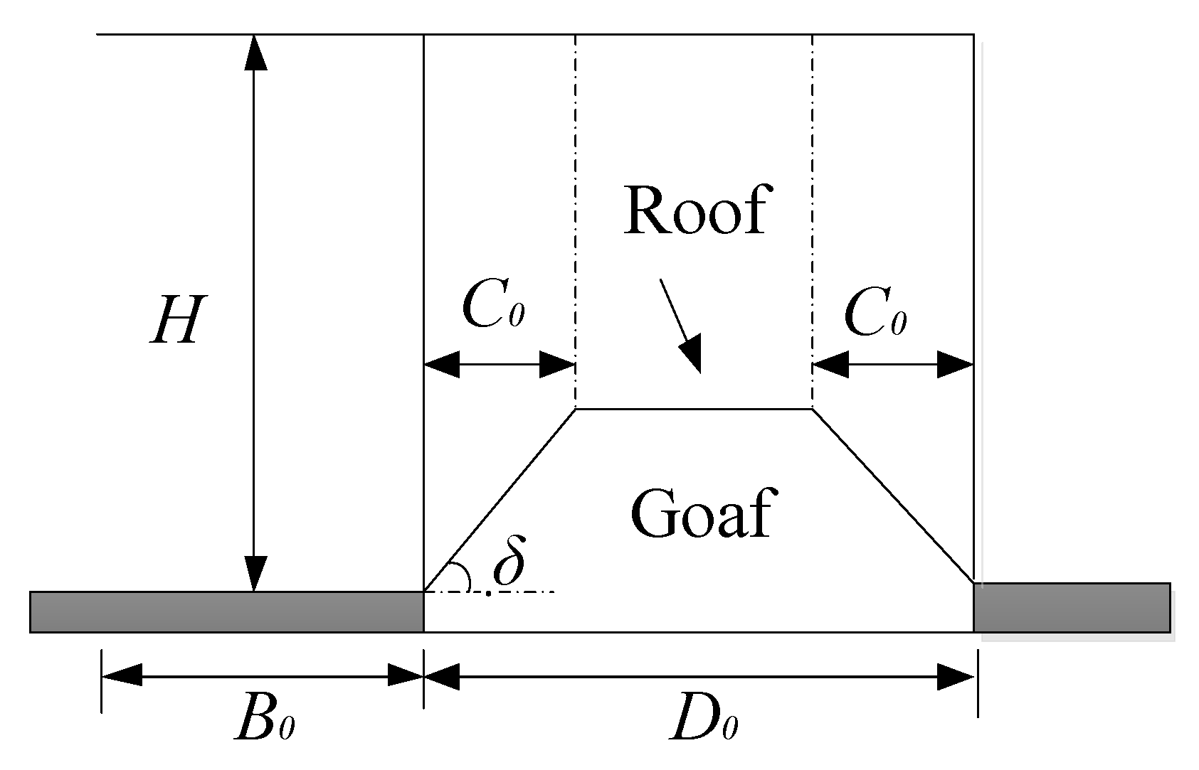
5.3. Hanging Roof Length L in the Goaf
5.4. Critical Coal Pillar Width B0
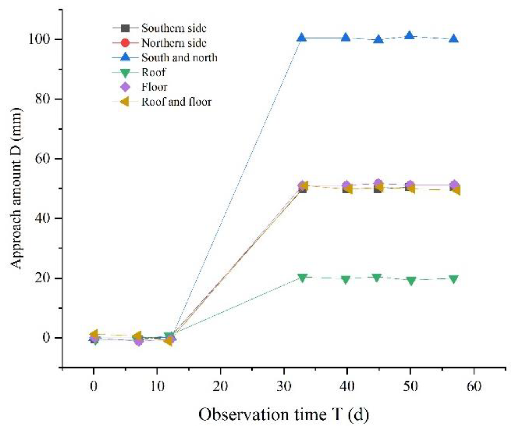
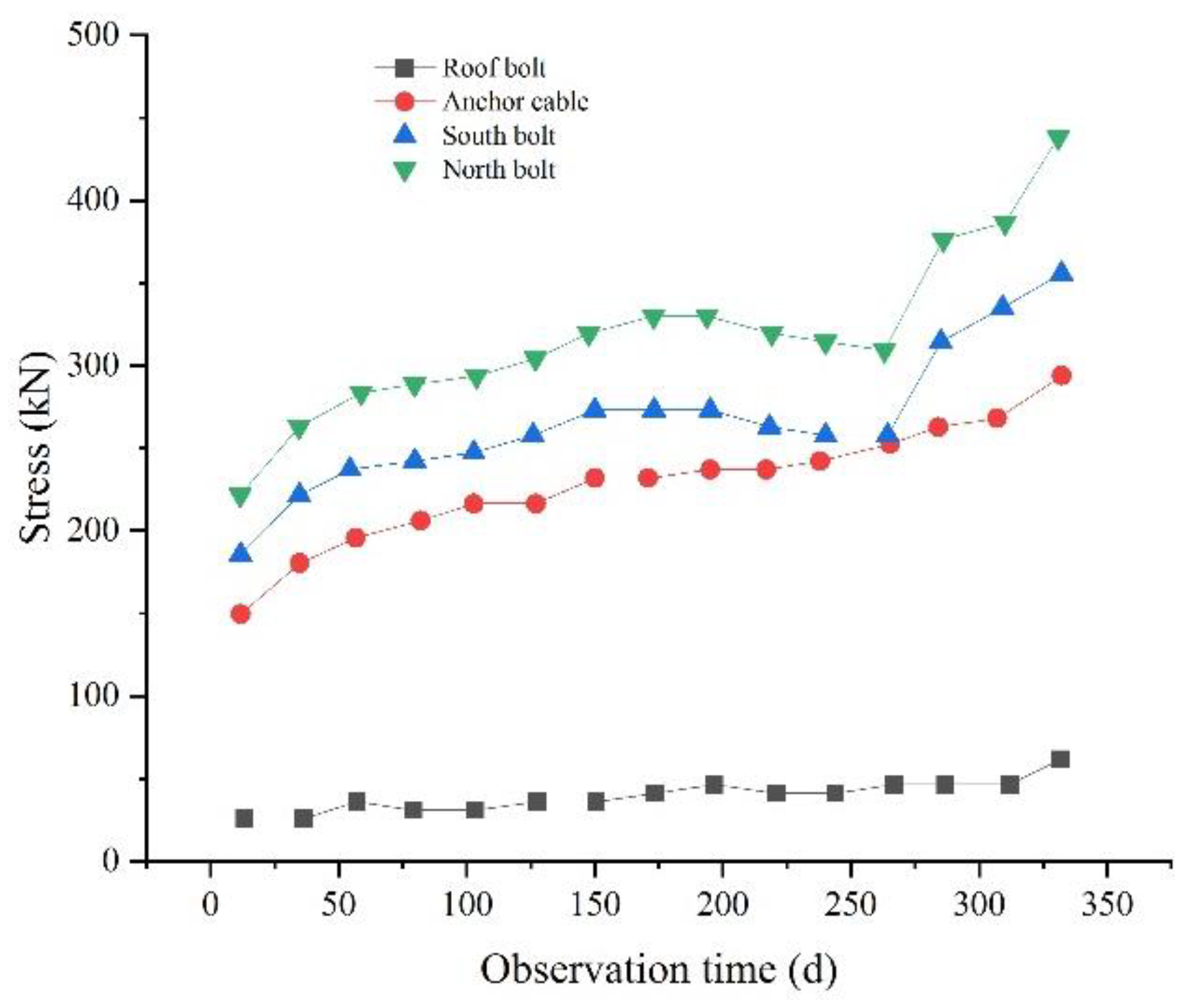
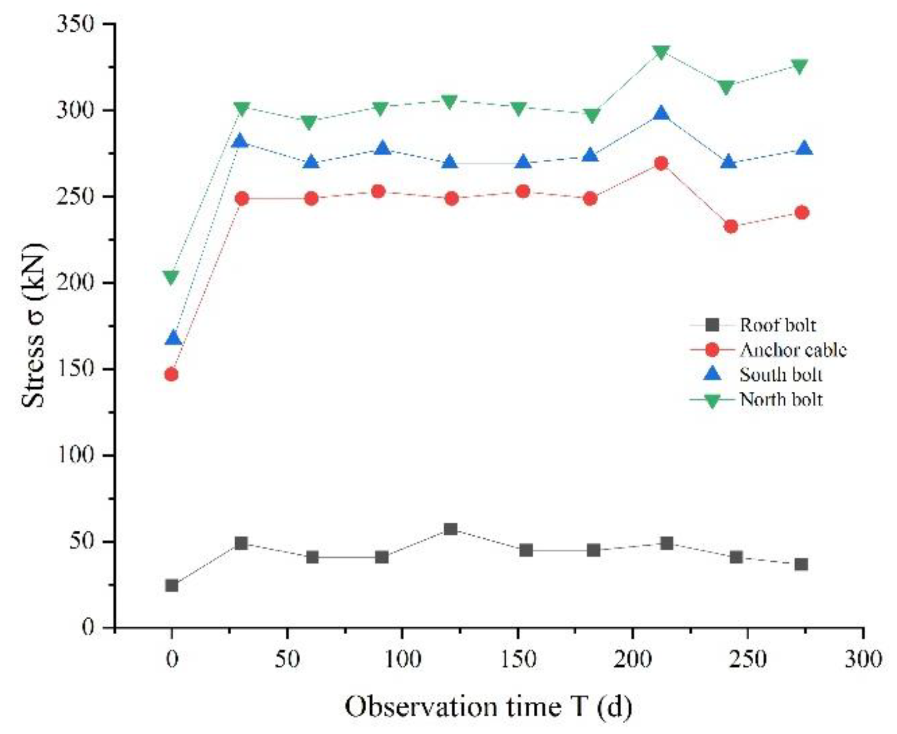
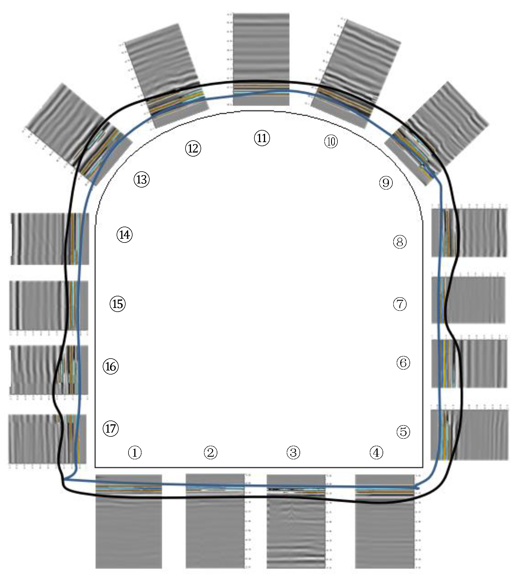
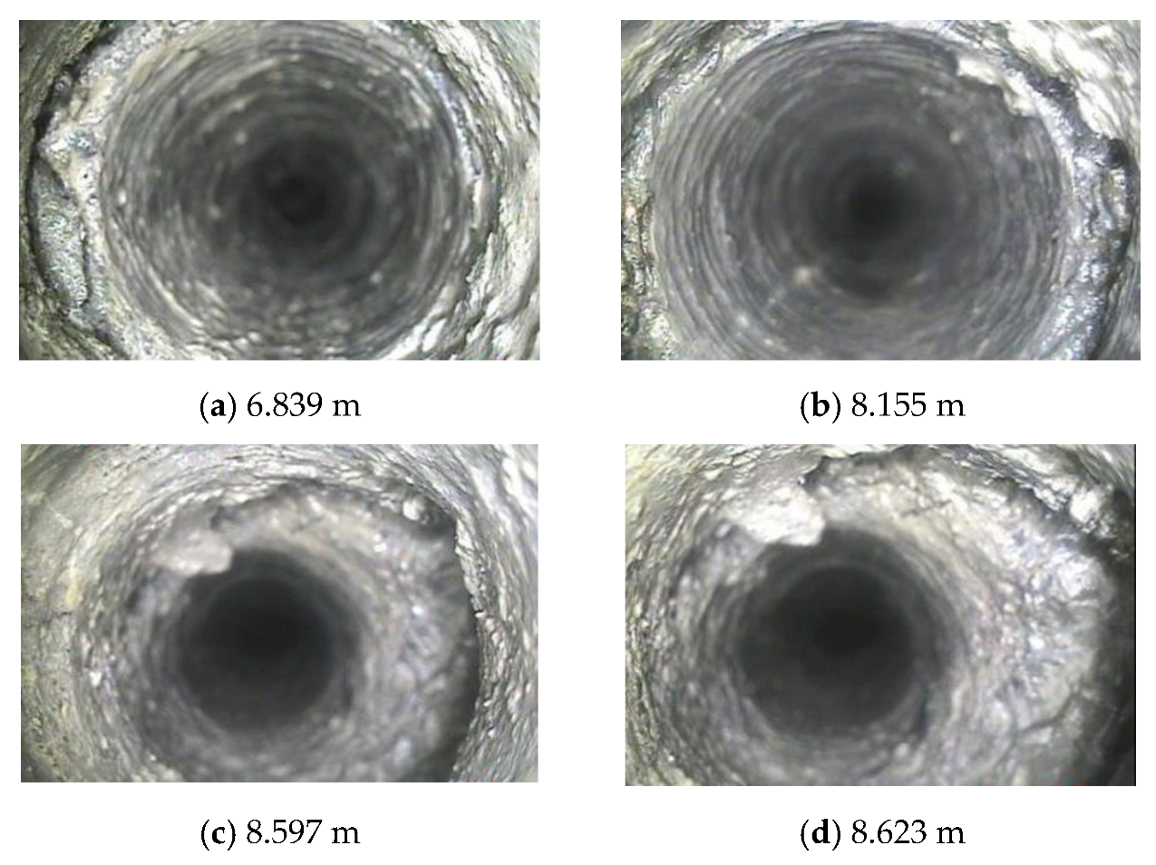
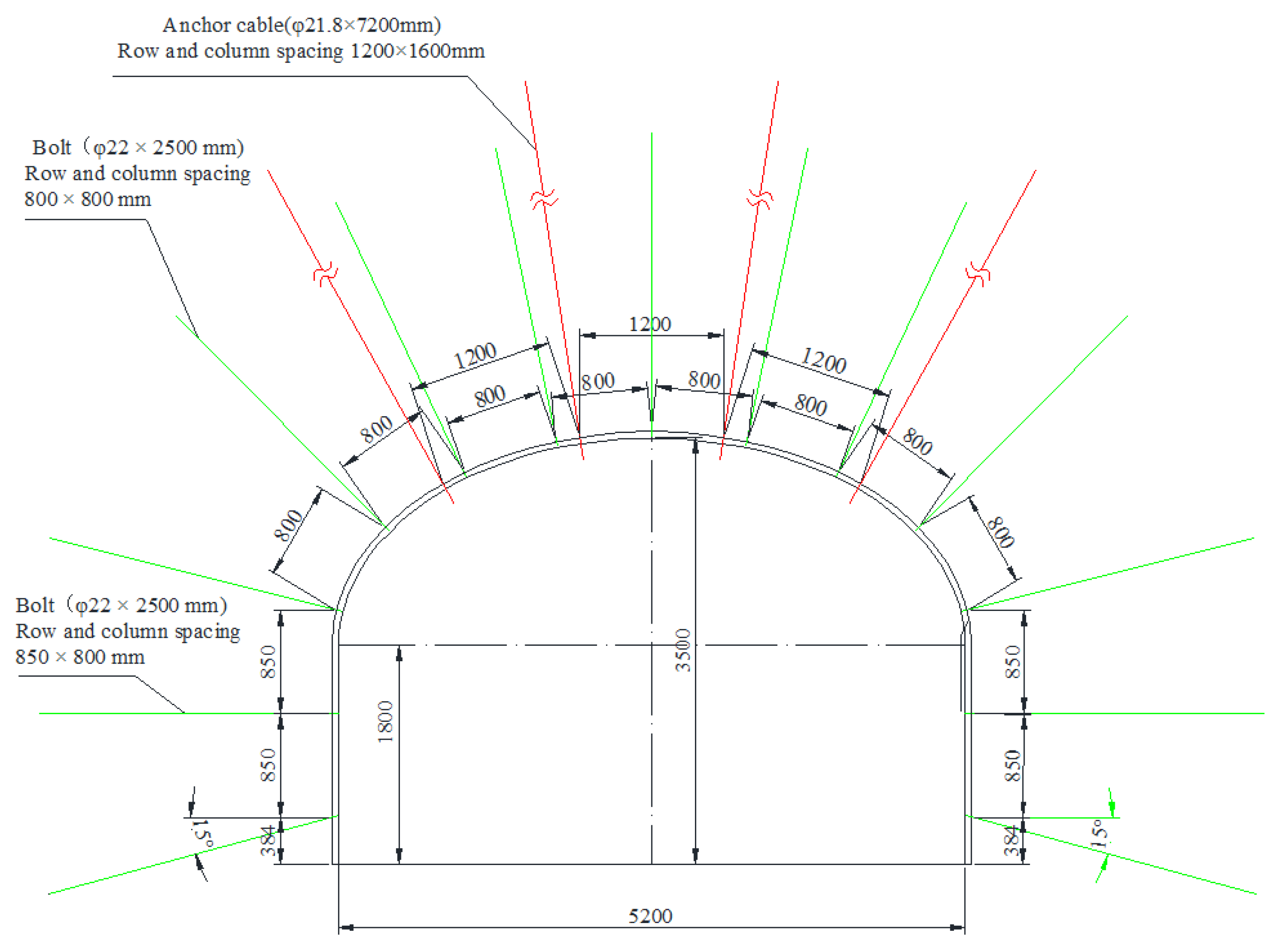
6. Investigation on Stability and Cementation of Surrounding Rock
7. Conclusions
Author Contributions
Funding
Institutional Review Board Statement
Informed Consent Statement
Data Availability Statement
Conflicts of Interest
References
- Hua, X.Z.; Yang, P. Floor deformation dynamic evolution of gob-side entry retaining with large section in deep mine. J. China Univ. Min. Technol. 2018, 47, 494–501. [Google Scholar]
- Zhang, N.; Chen, H.; Chen, Y. An engineering case of gob-side entry retaining in one kilometer-depth soft rock roadway with high ground pressure. J. China Coal Soc. 2015, 40, 494–501. [Google Scholar]
- Yang, P.; Hua, X.Z.; Yang, K.; Pang, D.D.; Cheng, S.X. Experiment of compound roof deformation characteristics of gob-side retaining entry in deep mine and support measures. J. Min. Saf. Eng. 2017, 34, 1067–1074. [Google Scholar]
- Zhang, G.F.; He, M.C.; Yu, X.P.; Huang, Z.G. Research on the Technique of No-Pillar Mining with Gob-Side Entry Formed by Advanced Roof Caving in the Protecticve Seamin Bai jiao Coal Mine. J. Min. Saf. Eng. 2011, 28, 511–516. [Google Scholar]
- He, M.C.; Chen, S.Y.; Guo, Z.B.; Yang, J.; Gao, Y.B. Control of surrounding rock structure for gob-side entry retaining by cutting roof to release pressure and its engineering application. J. China Univ. Min. Technol. 2017, 46, 959–969. [Google Scholar]
- He, M.C.; Ma, X.G.; Niu, F.L.; Wang, J.; Liu, Y.X. Adaptability research and application of rapid gob-side entry retaining formed by roof cutting and pressure releasing with composite roof and medium thick coal seam. Chin. J. Rock Mech. Eng. 2018, 37, 2641–2654. [Google Scholar]
- Hua, X.Z.; Liu, X.; Huang, Z.G.; Yang, P.; Ma, Y. Stability mechanism of non-pillar gob-side entry retaining by roof cutting under the coupled static-dynamic loading. J. China Coal Soc. 2020, 45, 3696–3708. [Google Scholar]
- Wang, F.T.; Shang, J.J.; Zhao, B.; Cao, Q.H. Surrounding rock structural characteristics and its anchor-cable strengthened support technology for the gob-side entry retaining with roof cutting and pressure releasing. Chin. J. Rock Mech. Eng. 2021, 40, 1–10. [Google Scholar] [CrossRef]
- He, M.C.; Wang, Y.; Yang, J.J.; Gao, Y.B.; Gao, Q.; Wang, S.B. Zonal characteristics and its influence factors of working face pressure using roof cutting and pressure-relief mining method with no pillar and roadway formed automaticly. J. China Univ. Min. Technol. 2018, 47, 1157–1165. [Google Scholar]
- Wang, J.; Zhu, D.Y.; Gong, W.L.; He, M.C.; Gao, R. Physical simulation experiment on the movement of rock strata upon automatic roadway forming by roof cutting and pressure releasing. Chin. J. Rock Mech. Eng. 2018, 37, 2536–2547. [Google Scholar]
- Liu, X.; Hua, X.Z.; Yang, P.; Huang, Z.G. A study of the mechanical structure of the direct roof during the whole process of non-pillar gob-side entry retaining by roof cutting. Energy Explor. Exploit. 2020, 38, 1706–1724. [Google Scholar] [CrossRef]
- Liu, X.; Hua, X.Z.; Huang, Z.G.; Yang, P.; Yang, S.; Chang, G.F. Dynamic instability mechanism of rock mass collapse with large structural plane under stress wave. Chin. J. Rock Mech. Eng. 2021, 40, 1–12. [Google Scholar] [CrossRef]
- Hua, X.Z.; Chang, G.F.; Liu, X.; Sun, B.J.; Yang, S.; Wang, E.Q.; Li, C. Three-Dimensional Physical Simulation and Control Technology of Roof Movement Characteristics in Non-Pillar Gob-Side Entry Retaining by Roof Cutting. Shock Vib. 2021, 2021, 7491414. [Google Scholar] [CrossRef]
- Gao, Y.B.; Yang, J.; He, M.C.; Wang, Y.J.; Gao, Q. Mechanism and control techniques for gangue rib deformations in gob-side entry retaining formed by roof fracturing in thick coal seams. Chin. J. Rock Mech. Eng. 2017, 36, 2492–2502. [Google Scholar]
- Chen, Y.; Hao, S.P.; Chen, Y.T.; Zhang, Z.Z.; Wu, L.F.; Liu, H.L. Study on the application of short-hole blasting with guide hole to roof cutting pressure relief of gob-side entry retaining. J. Min. Saf. Eng. 2015, 32, 253–259. [Google Scholar]
- Zhang, B.S.; Wang, P.F.; Cui, S.Q.; Fan, M.Z.; Qiu, Y.M. Mechanism and surrounding rock control of roadway driving along gob in shallow-buried, large mining height and small coal pillars by roof cutting. J. China Coal Soc. 2021, 46, 2254–2267. [Google Scholar]
- Su, C.; Gong, P.L.; Kang, H.P.; Li, C.; Yi, K.; Liu, C.; Li, P. Mechanism of roof cutting and pressure relief in gob-side and high-stress roadway in deep coal mine. J. Min. Saf. Eng. 2020, 37, 1104–1113. [Google Scholar]
- Xue, W.F.; Wang, S.J.; Huang, K.J.; Ji, R.J.; Liu, M.L.; Ren, Y.L.; Xi, X.P.; Wang, F. Theoretical analysis and field measurement of floor failure in gob side entry of cutting roof in confined water mine area. J. China Coal Soc. 2020, 45, 581–588. [Google Scholar]
- Yang, J.; Wei, Q.L.; Wang, Y.J.; Gao, Y.B.; Hou, S.L.; Qiao, B.W. Roof deformation mechanism and control measures of pillarless mining with gob-side entry retaining by roof cutting and pressure relief. Rock Soil Mech. 2020, 41, 989–998. [Google Scholar]
- Yang, H.Y.; Li, Y.; Liu, Y.B.; Cao, S.G.; Pan, R.K.; Wang, H.; Wang, B.; Chen, X. Structure evolution and stability control mechanism of hard-roof cutting for roadway retaining. J. Min. Saf. Eng. 2021, 38, 766–773. [Google Scholar]
- Lin, J.; Guo, K.; Sun, Z.Y.; Wang, T. Study on fracturing timing of hydraulic fracturing top-cutting and pressure relief in roadway with strong dynamic pressure. J. China Coal Soc. 2020, 48, 1–9. [Google Scholar] [CrossRef]
- Wang, X.G. Blasting Manual; Metallurgical Industry Press: Beijing, China, 2010; pp. 263–364. [Google Scholar]
- Dai, J. Blasting Engineering; Mechanical Industry Press: Beijing, China, 2021; pp. 126–251. [Google Scholar]
- Duan, F.B. Engineering Blasting; Peking University Press: Beijing, China, 2012; pp. 149–267. [Google Scholar]
- Xu, J.L.; Qian, M.G. Method to distinguish key strata in overburden. J. China Univ. Min. Technol. 2000, 29, 463–467. [Google Scholar]
- Li, Y.F.; Hua, X.Z.; Wang, X.H.; Yang, K. Dynamic weight classification and differentiated support on mining roadway in Wanbei minefield. J. Min. Saf. Eng. 2017, 34, 1042–1050. [Google Scholar]
- Liu, Z.H.; Yang, L.S.; Song, X.M.; Zhao, Y.S.; Feng, Z.C.; Yang, D. Stress control of deep cutting along roadway over roof rock. J. Min. Saf. Eng. 2014, 31, 347–353. [Google Scholar]


| NO. | Lithology | Thickness (m) | Elastic Modulus E/(GPa) | Tensile Strength σt (MPa) | Compressive Strength σc (MPa) | Density ρ (/kg·m−3) | Coefficient of Dilatancy |
|---|---|---|---|---|---|---|---|
| 11 | Sandy mudstone | 16.95 | 21.04 | 2.96 | 58.72 | 2507 | 1.15 |
| 10 | Mudstone | 2.80 | 12.35 | 2.17 | 36.27 | 2461 | 1.20 |
| 9 | Quartz sandstone | 7.65 | 35.72 | 8.91 | 158.7 | 2684 | 1.15 |
| 8 | Fine sandstone | 5.06 | 30.45 | 5.85 | 89.07 | 2596 | 1.15 |
| 7 | Mudstone | 2.12 | 13.59 | 1.86 | 30.17 | 2448 | 1.20 |
| 6 | #9 coal seam | 0.62 | / | / | / | / | 1.25 |
| 5 | Mudstone | 0.41 | 11.84 | 1.28 | 32.15 | 2463 | 1.20 |
| 4 | #9 lower coal seam | 0.55 | / | / | / | / | 1.25 |
| 3 | Mudstone | 0.98 | 14.15 | 1.58 | 34.86 | 2485 | 1.20 |
| 2 | Fine sandstone | 9.32 | 37.15 | 3.38 | 128.0 | 2532 | 1.15 |
| 1 | Mudstone | 4.50 | 12.15 | 2.04 | 43.12 | 2417 | 1.20 |
| 0 | 8# coal seam | 3.22 | / | / | / | / | 1.25 |
Publisher’s Note: MDPI stays neutral with regard to jurisdictional claims in published maps and institutional affiliations. |
© 2022 by the authors. Licensee MDPI, Basel, Switzerland. This article is an open access article distributed under the terms and conditions of the Creative Commons Attribution (CC BY) license (https://creativecommons.org/licenses/by/4.0/).
Share and Cite
Yue, X.; Tu, M.; Li, Y.; Chang, G.; Li, C. Stability and Cementation of the Surrounding Rock in Roof-Cutting and Pressure-Relief Entry under Mining Influence. Energies 2022, 15, 951. https://doi.org/10.3390/en15030951
Yue X, Tu M, Li Y, Chang G, Li C. Stability and Cementation of the Surrounding Rock in Roof-Cutting and Pressure-Relief Entry under Mining Influence. Energies. 2022; 15(3):951. https://doi.org/10.3390/en15030951
Chicago/Turabian StyleYue, Xizhan, Min Tu, Yingfu Li, Guanfeng Chang, and Chen Li. 2022. "Stability and Cementation of the Surrounding Rock in Roof-Cutting and Pressure-Relief Entry under Mining Influence" Energies 15, no. 3: 951. https://doi.org/10.3390/en15030951
APA StyleYue, X., Tu, M., Li, Y., Chang, G., & Li, C. (2022). Stability and Cementation of the Surrounding Rock in Roof-Cutting and Pressure-Relief Entry under Mining Influence. Energies, 15(3), 951. https://doi.org/10.3390/en15030951