
Experimental Study on the Pyrolysis and Soot Formation Characteristics of JP-10 Jet Fuel


Abstract
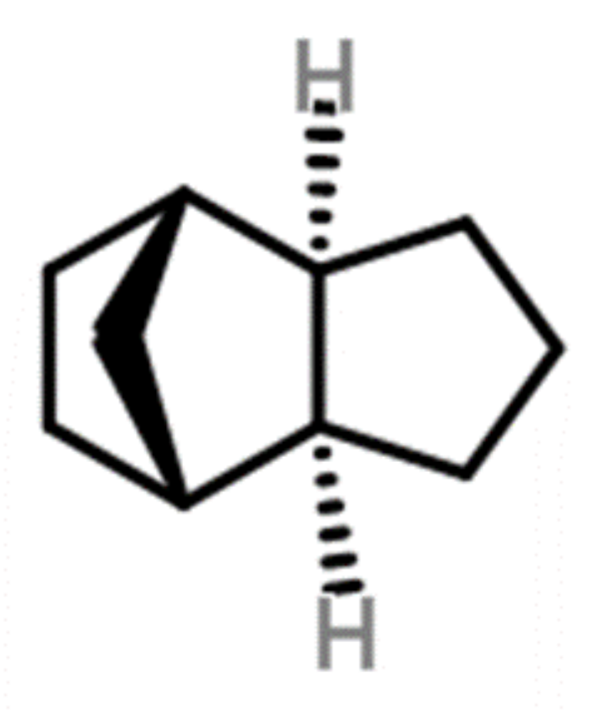
:1. Introduction
2. Methodology
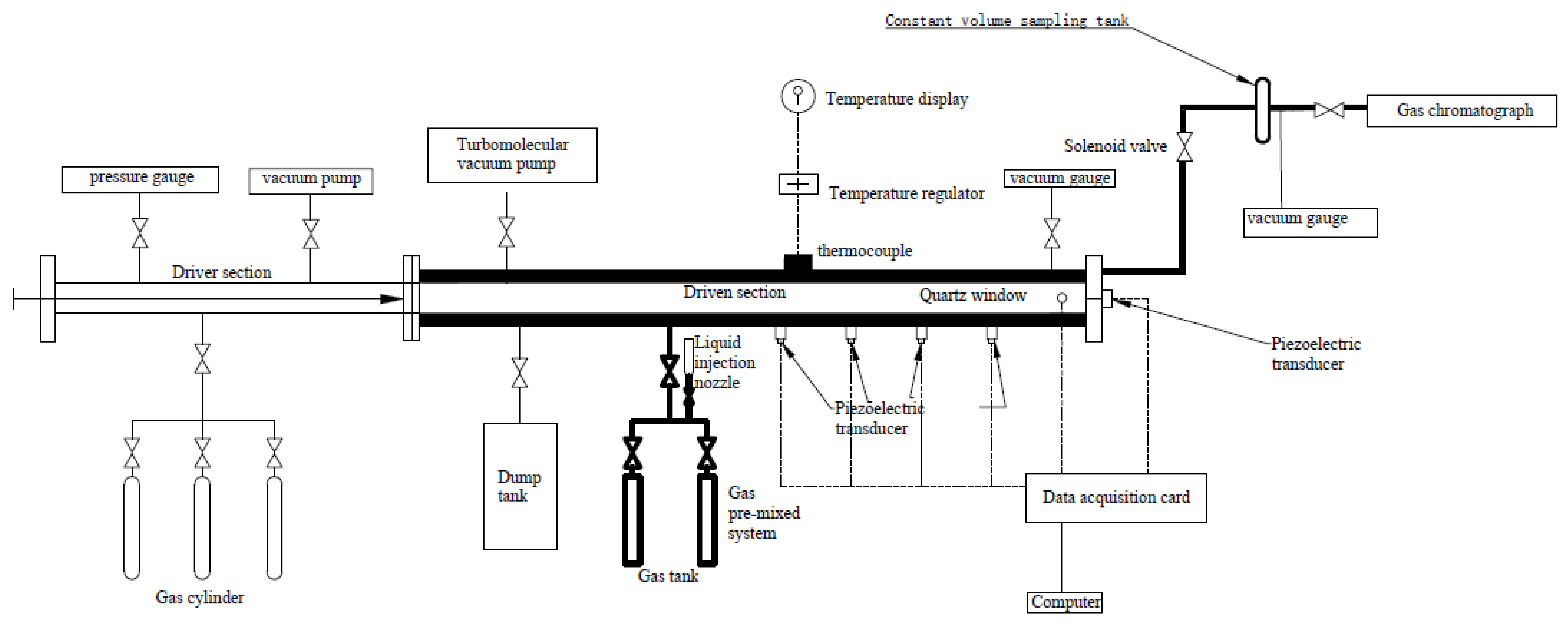
2.1. Single-Pulse Shock Tube (SPST)
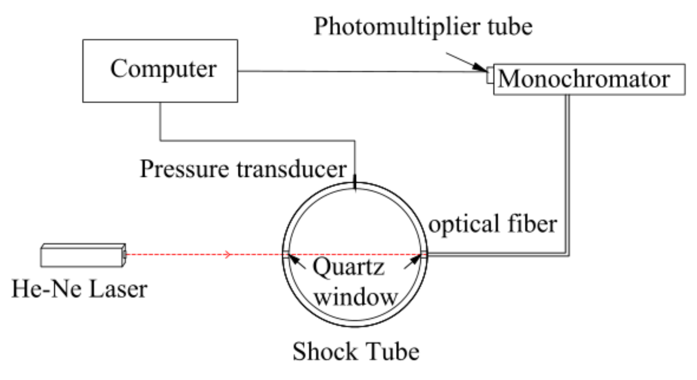
2.2. High-Pressure Shock Tube (HPST)
2.3. Mixture Preparation
3. Results and Discussion
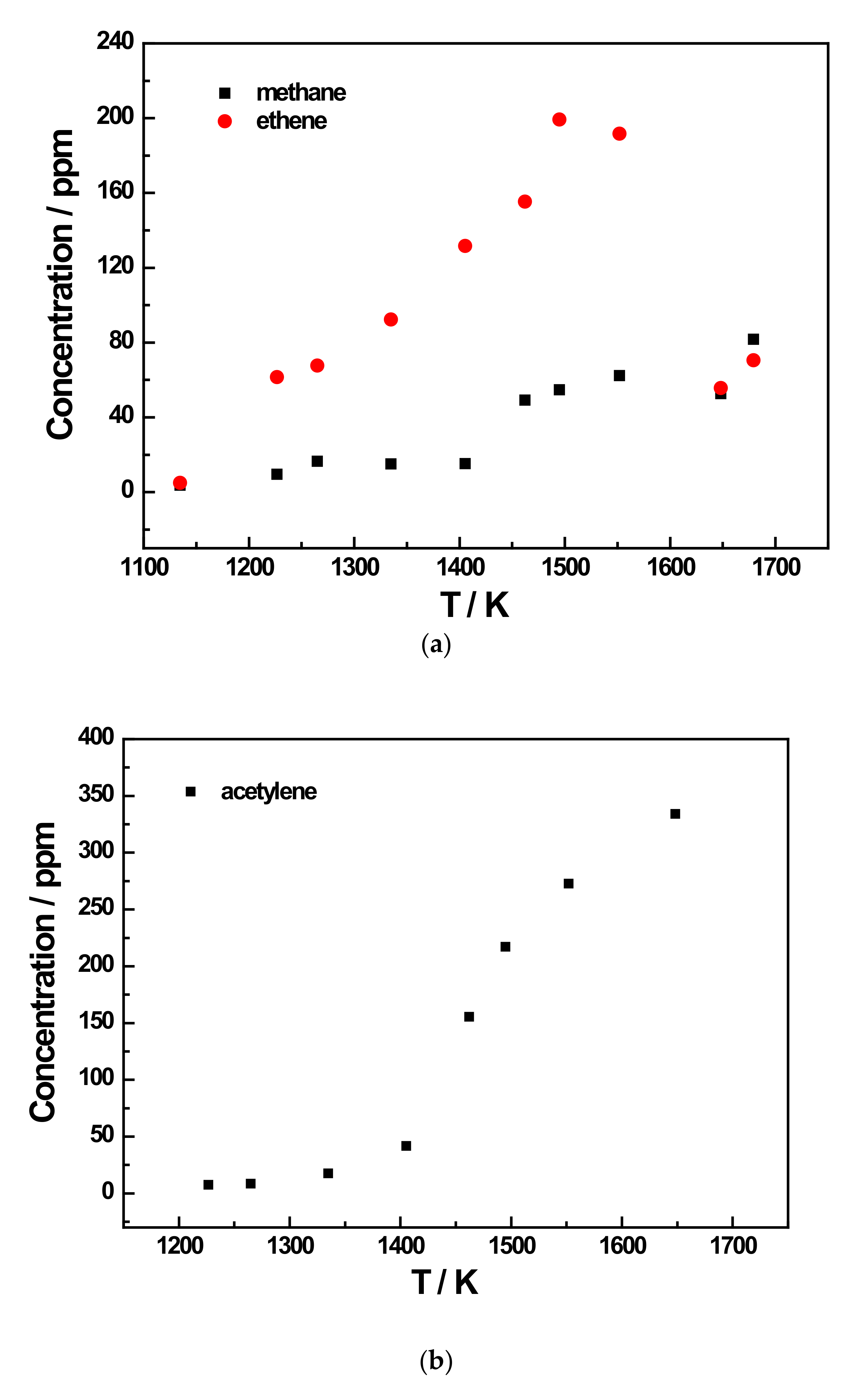
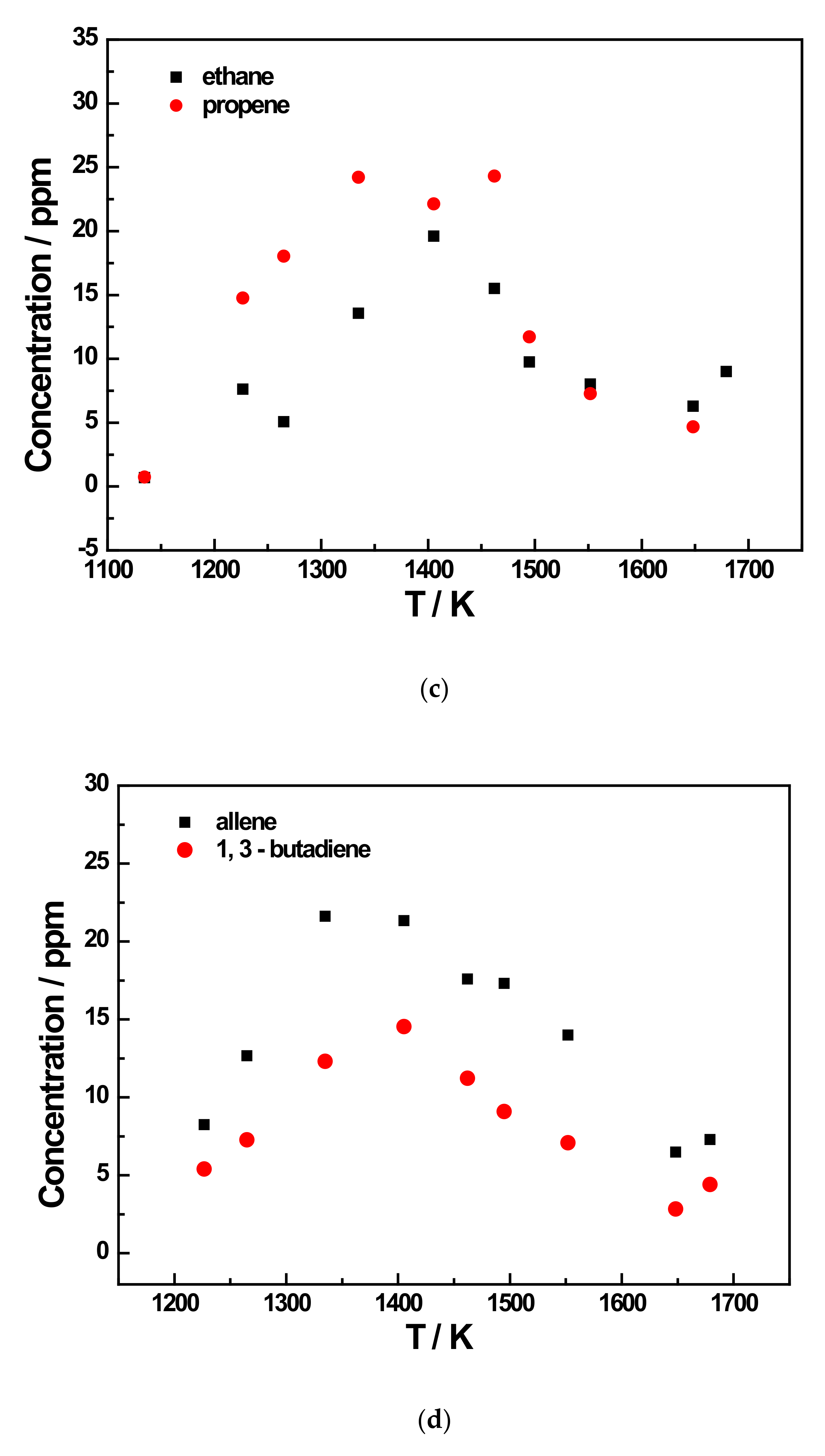
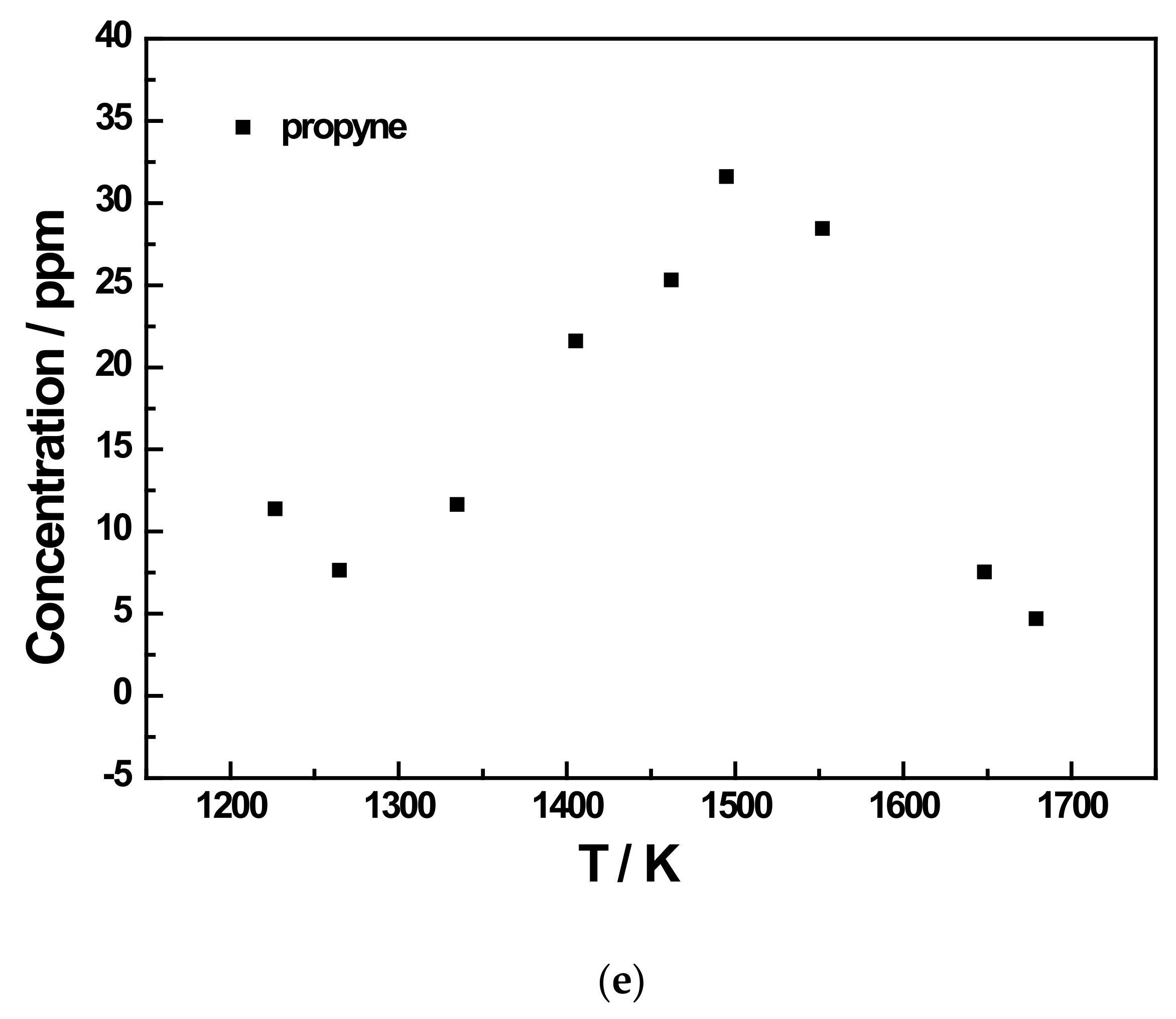
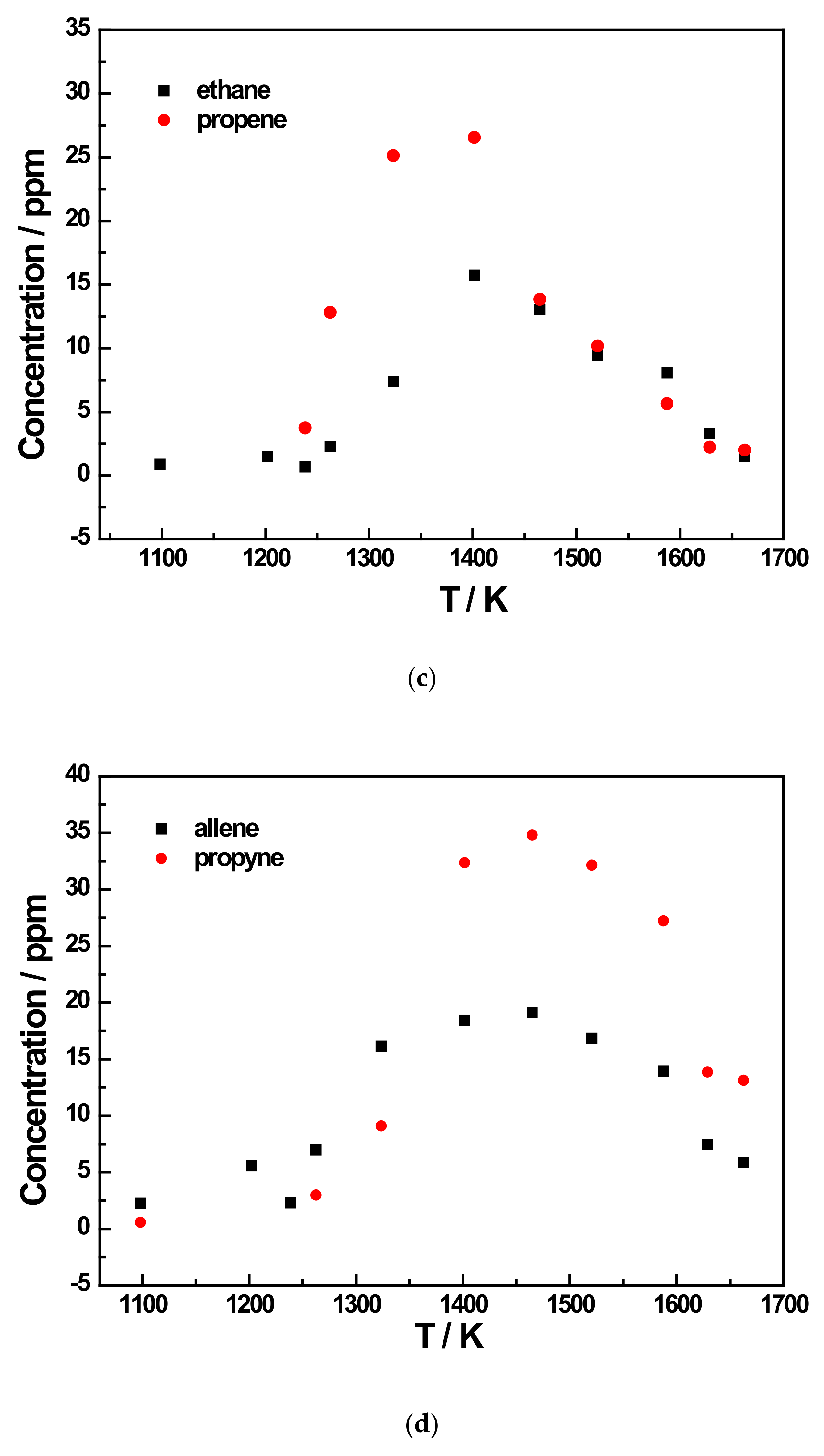
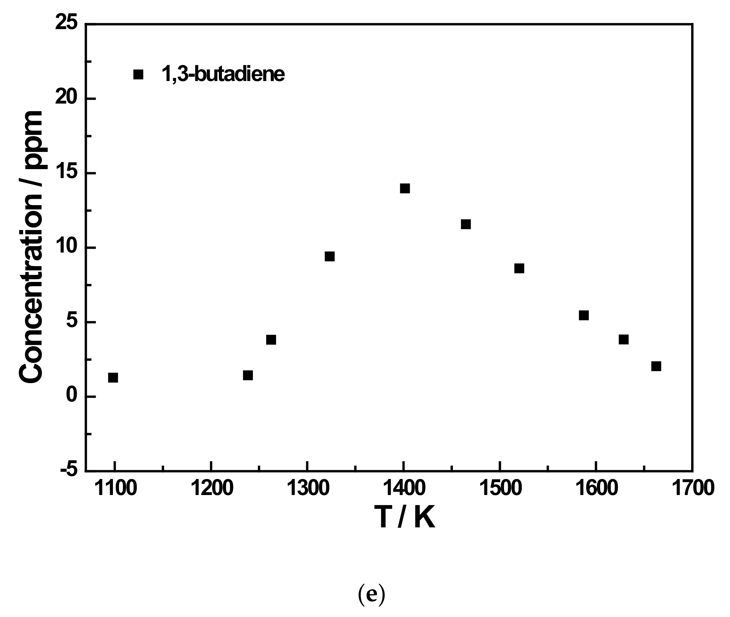
3.1. SPST Pyrolysis Results
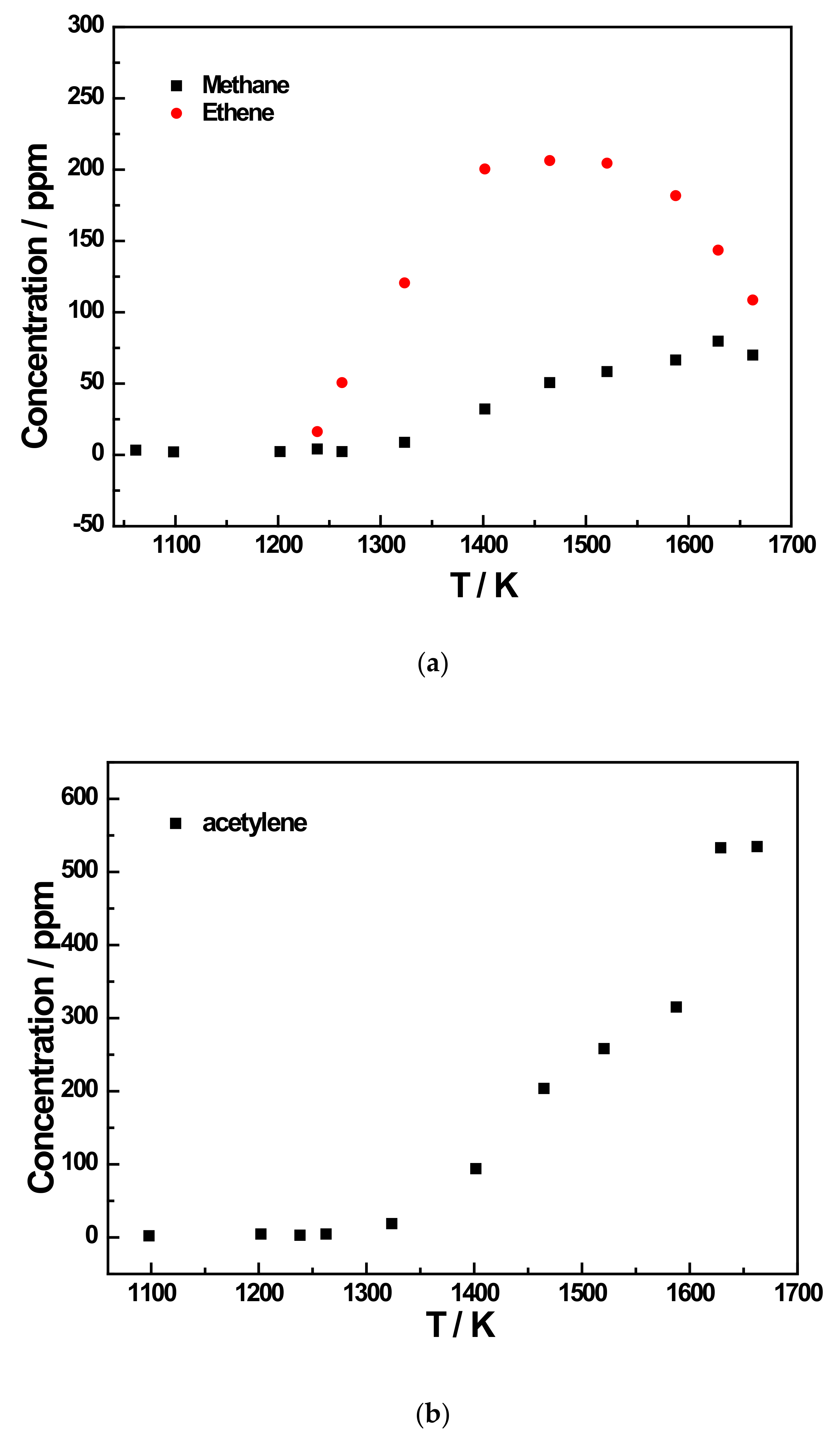
3.2. HPST Soot-Related Experiment Results
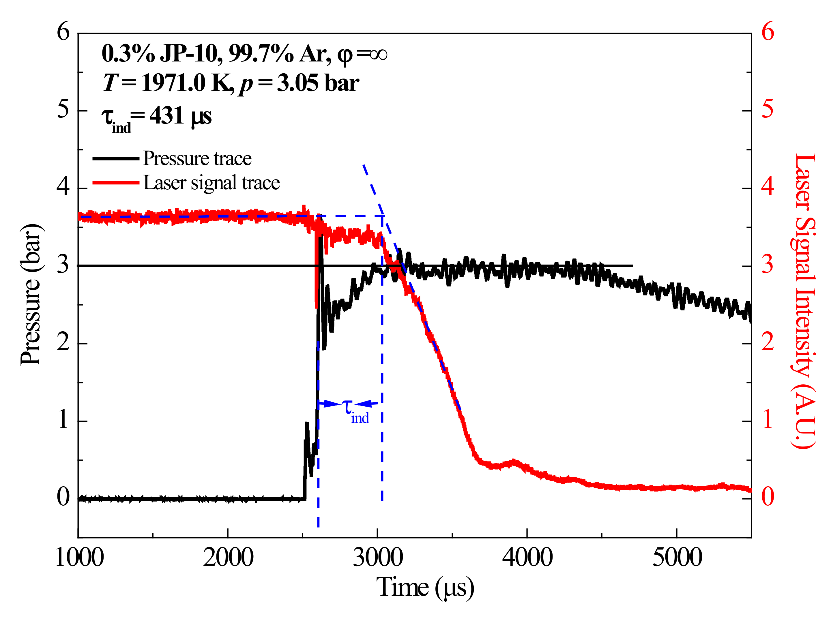
3.2.1. Soot-Induction Delay Times
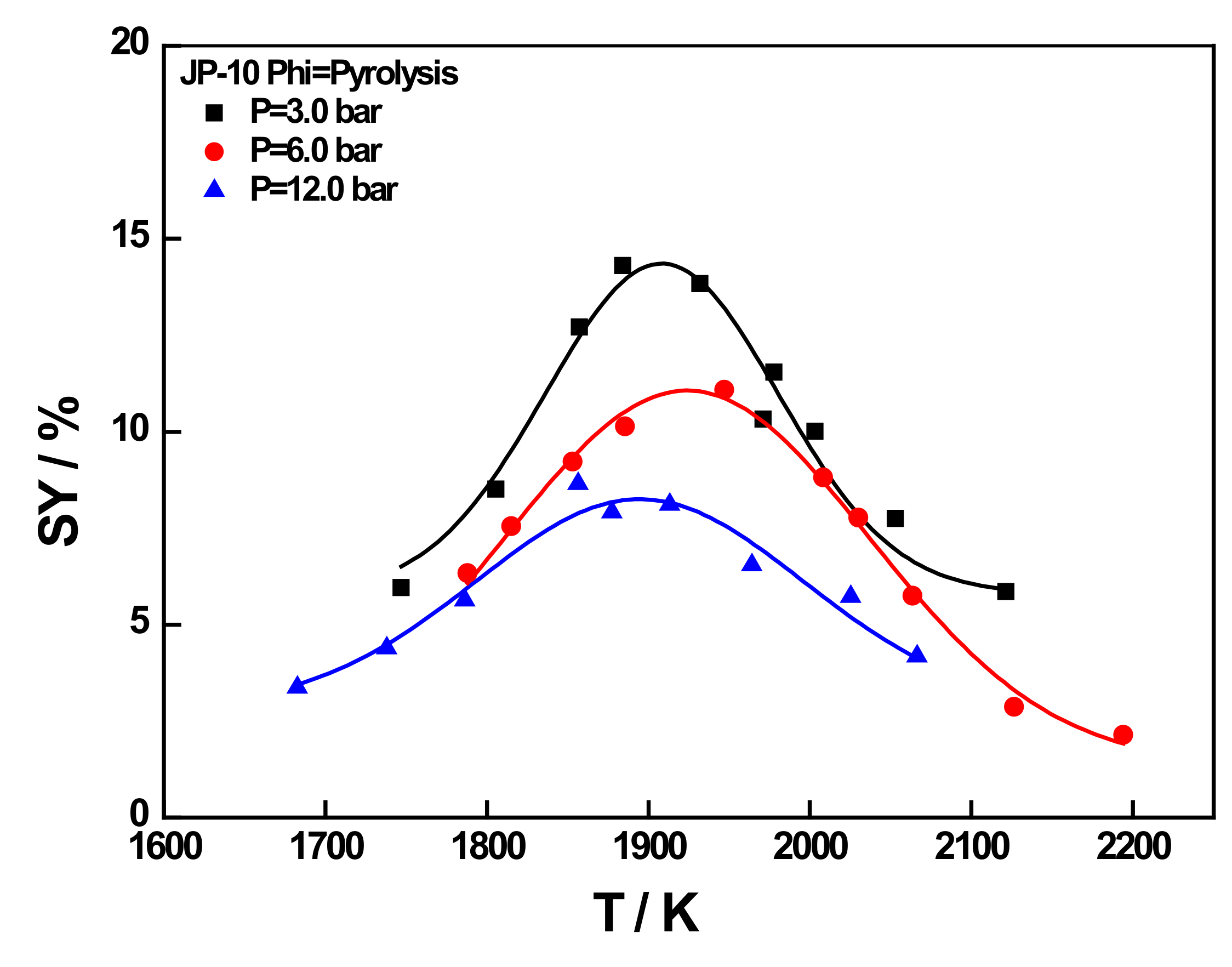
3.2.2. Soot Yield
4. Conclusions
Author Contributions
Funding
Institutional Review Board Statement
Informed Consent Statement
Acknowledgments
Conflicts of Interest
References
- Ishchenko, A.N.; Maslov, E.A.; Skibina, N.P.; Faraponov, V.V. Complex Investigation of Nonstationary Flow with Shock Waves in the Working Path of a Hypersonic Ramjet Engine. J. Eng. Phys. Thermophys. 2021, 94, 450–457. [Google Scholar] [CrossRef]
- Ojha, P.K.; Prabhudeva, P.; Karmakar, S.; Maurya, D.; Sivaramakrishna, G. Combustion characteristics of JP-10 droplet loaded with Sub-micron boron particles. Exp. Therm. Fluid Sci. 2019, 109, 109900. [Google Scholar] [CrossRef]
- Chen, B.H.; Liu, J.Z.; Yao, F.; Li, H.P.; Zhou, J.H. Effect of oleic acid on the stability and rheology of nanoaluminium/JP-10 bi-phase system. Micro Nano Lett. 2017, 12, 675–679. [Google Scholar] [CrossRef]
- Chickos, J.S.; Hillesheim, D.; Nichols, G.; Zehe, M.J. The enthalpies of vaporization and sublimation of exo- and endo-tetrahydrodicyclopentadienes at T = 298.15 K. J. Chem. Thermodyn. 2002, 34, 1647–1658. [Google Scholar] [CrossRef]
- Kohse-Höinghaus, K. Combustion Chemistry Diagnostics for Cleaner Processes. Chem.—A Eur. J. 2016, 22, 13390–13401. [Google Scholar] [CrossRef]
- Wang, W. Formation of nascent soot and other condensed-phase materials in flames. Proc. Combust. Inst. 2011, 33, 1341–1367. [Google Scholar] [CrossRef]
- Wang, Y.; Chung, S.H. Soot formation in laminar counterflow flames. Prog. Energy Combust. Sci. 2019, 74, 152–238. [Google Scholar] [CrossRef]
- Barak, S.; Rahman, R.K.; Neupane, S.; Ninnemann, E.; Arafin, F.; Laich, A.; Terracciano, A.C.; Vasu, S.S. Measuring the effectiveness of high-performance Co-Optima biofuels on suppressing soot formation at high temperature. Proc. Natl. Acad. Sci. USA 2020, 117, 3451–3460. [Google Scholar] [CrossRef]
- Li, X.; Ma, Z.; Lv, E.; Dong, Y.; Wang, X. Experimental and kinetic study of hydrocarbon fuel pyrolysis in a shock tube. Fuel 2021, 304, 121521. [Google Scholar] [CrossRef]
- Kumar, K.; Sung, C.-J. An experimental study of the autoignition characteristics of conventional jet fuel/oxidizer mixtures: Jet-A and JP-8. Combust. Flame 2010, 157, 676–685. [Google Scholar] [CrossRef]
- Allen, C.; Valco, D.; Toulson, E.; Edwards, T.; Lee, T. Ignition behavior and surrogate modeling of JP-8 and of camelina and tallow hydrotreated renewable jet fuels at low temperatures. Combust. Flame 2013, 160, 232–239. [Google Scholar] [CrossRef] [Green Version]
- Dagaut, P.; Karsenty, F.; Dayma, G.; Diévart, P.; Hadj-Ali, K.; Mzé-Ahmed, A.; Braun-Unkhoff, M.; Herzler, J.; Kathrotia, T.; Kick, T.; et al. Experimental and detailed kinetic model for the oxidation of a Gas to Liquid (GtL) jet fuel. Combust. Flame 2014, 161, 835–847. [Google Scholar] [CrossRef] [Green Version]
- Nagaraja, S.S.; Liang, J.; Dong, S.; Panigrahy, S.; Sahu, A.; Kukkadapu, G.; Wagnon, S.W.; Pitz, W.J.; Curran, H.J. A hierarchical single-pulse shock tube pyrolysis study of C2–C6 1-alkenes. Combust. Flame 2020, 219, 456–466. [Google Scholar] [CrossRef]
- He, J.; Xian, L.; Li, P.; Zhang, C.; Wang, J.; Li, X. Experimental study of the soot formation of RP-3 behind reflected shock waves. Fuel 2017, 200, 47–53. [Google Scholar] [CrossRef]
- De Toni, A.; Werler, M.; Hartmann, R.; Cancino, L.; Schießl, R.; Fikri, M.; Schulz, C.; Oliveira, A.; Oliveira, E.; Rocha, M. Ignition delay times of Jet A-1 fuel: Measurements in a high-pressure shock tube and a rapid compression machine. Proc. Combust. Inst. 2017, 36, 3695–3703. [Google Scholar] [CrossRef]
- Vasu, S.S.; Davidson, D.F.; Hanson, R.K. Jet fuel ignition delay times: Shock tube experiments over wide conditions and surrogate model predictions. Combust. Flame 2008, 152, 125–143. [Google Scholar] [CrossRef]
- Wang, B.Y.; Zeng, P.; He, R.; Li, F.; Yang, Z.Y.; Xia, Z.X.; Liang, J.; Wang, Q.D. Single-Pulse Shock Tube Experimental and Kinetic Modeling Study on Pyrolysis of a Direct Coal Liquefaction-Derived Jet Fuel and Its Blends with the Traditional RP-3 Jet Fuel. ACS Omega 2021, 6, 18442–18450. [Google Scholar] [CrossRef]
- Zeng, P.; Wang, B.Y.; He, R.; Liang, J.; Yang, Z.Y.; Xia, Z.X.; Wang, Q.D. Single-Pulse Shock Tube Pyrolysis Study of RP-3 Jet Fuel and Kinetic Modeling. ACS Omega 2021, 6, 11039–11047. [Google Scholar] [CrossRef]
- Mathieu, O.; Chaumeix, N.; Paillard, C.-E. Soot formation from a distillation cut of a Fischer–Tropsch diesel fuel: A shock tube study. Combust. Flame 2012, 159, 2192–2201. [Google Scholar] [CrossRef]
- Xiong, Z.; Wang, S. Shock-Tube and Kinetic Modeling Study of JP-10 Pyrolysis. In Proceedings of the Abstracts of Second International Conference on High Temperature Gas Dynamics, Beijing, China, 23–25 June 2016; p. 118. [Google Scholar]
- Zhuang, X.; Su, W.; Can, Z.; Hongru, Y. Shock-tube experimental study and konetic modeling of JP-10 pyrolysis. Lixue Xuebao/Chin. J. Theor. Appl. Mech. 2019, 51, 85–93. [Google Scholar]
- Gao, C.W.; Vandeputte, A.G.; Yee, N.W.; Green, W.H.; Bonomi, R.E.; Magoon, G.R.; Wong, H.W.; Oluwole, O.O.; Lewis, D.K.; Vandewiele, N.M.; et al. JP-10 combustion studied with shock tube experiments and modeled with automatic reaction mechanism generation. Combust. Flame 2015, 162, 3115–3129. [Google Scholar] [CrossRef] [Green Version]
- Zhong, B.-J.; Zeng, Z.-M.; Zhang, H.-Z. An experimental and kinetic modeling study of JP-10 combustion. Fuel 2021, 312, 122900. [Google Scholar] [CrossRef]
- Chenoweth, K.; van Duin, A.C.T.; Dasgupta, S.; Iii, W.A.G. Initiation Mechanisms and Kinetics of Pyrolysis and Combustion of JP-10 Hydrocarbon Jet Fuel. J. Phys. Chem. A 2009, 113, 1740–1746. [Google Scholar] [CrossRef] [PubMed] [Green Version]
- Davidson, D.; Horning, D.; Oehlschlaeger, M.; Hanson, R. The decomposition products of JP-10. In Proceedings of the 37th Joint Propulsion Conference and Exhibit; American Institute of Aeronautics and Astronautics (AIAA), Salt Lake City, UT, USA, 8–11 July 2001. [Google Scholar]
- Johnson, S.E.; Davidson, D.F.; Hanson, R.K. Shock tube/laser absorption measurements of the pyrolysis of JP-10 fuel. Combust. Flame 2020, 216, 161–173. [Google Scholar] [CrossRef]
- Wang, Y.; Cheng, Y.; Li, M.; Jiang, P.-X.; Zhu, Y. Experimental and theoretical modeling of the effects of pressure and secondary reactions on pyrolysis of JP-10 at supercritical pressures. Fuel 2021, 306, 121737. [Google Scholar] [CrossRef]
- Nagaraja, S.S.; Power, J.; Kukkadapu, G.; Dong, S.; Wagnon, S.W.; Pitz, W.J.; Curran, H.J. A single pulse shock tube study of pentene isomer pyrolysis. Proc. Combust. Inst. 2021, 38, 881–889. [Google Scholar] [CrossRef]
- Panigrahy, S.; Liang, J.; Nagaraja, S.S.; Zuo, Z.; Kim, G.; Dong, S.; Kukkadapu, G.; Pitz, W.J.; Vasu, S.S.; Curran, H.J. A comprehensive experimental and improved kinetic modeling study on the pyrolysis and oxidation of propyne. Proc. Combust. Inst. 2021, 38, 479–488. [Google Scholar] [CrossRef]
- Yang, Z.-Y.; Zeng, P.; Wang, B.-Y.; Jia, W.; Xia, Z.-X.; Liang, J.; Wang, Q.-D. Ignition characteristics of an alternative kerosene from direct coal liquefaction and its blends with conventional RP-3 jet fuel. Fuel 2021, 291, 120258. [Google Scholar] [CrossRef]
- Wu, Y.; Panigrahy, S.; Sahu, A.B.; Bariki, C.; Beeckmann, J.; Liang, J.; Mohamed, A.A.; Dong, S.; Tang, C.; Pitsch, H.; et al. Understanding the antagonistic effect of methanol as a component in surrogate fuel models: A case study of methanol/n-heptane mixtures. Combust. Flame 2021, 226, 229–242. [Google Scholar] [CrossRef]
- Liang, J.; Li, X.; Li, F.; Wang, B.-Y.; Zeng, P.; Yang, Z.-Y.; Xia, Z.-X.; Wang, Q.-D. Experimental study on sooting characteristics of a direct coal liquefaction derived jet fuel and its blend with RP-3 jet fuel. Fuel 2021, 307, 121846. [Google Scholar] [CrossRef]
- Hong, Z.; Davidson, D.; Vasu, S.; Hanson, R. The effect of oxygenates on soot formation in rich heptane mixtures: A shock tube study. Fuel 2009, 88, 1901–1906. [Google Scholar] [CrossRef]
- Chang, H.-C.; Charalampopoulos, T.T. Determination of the wavelength dependence of refractive indices of flame soot. Proc. R. Soc. Lond. Ser. A Math. Phys. Sci. 1990, 430, 577–591. [Google Scholar] [CrossRef]


| Year | Ref. | Fuel | Apparatus |
|---|---|---|---|
| 2017 | Toni [15] | A1 jet engine fuel sample | Rapid compression machine and high-pressure shock tube |
| 2007 | Subitsh [16] | Jet-A and JP 8 | High-pressure shock tube. |
| 2021 | Biyao [17,18] | Direct coal liquefaction (DCL) and RP-3 jet fuel | Single-pulse shock tube |
| 2012 | Olivier [19] | Fischer–Tropsch (FT) fuel | Shock tube |
| Authors | Pressure/Atm | Temperature | Year Published | Apparatus |
|---|---|---|---|---|
| Davidson et al. [25] | 1.2–1.5 | 1100–1700 | 2013 | Shock tube |
| Johnson et al. [26] | 2.5–3.0 | 1150–1550 | 2020 | Shock tube |
| Wang et al. [27] | 35–70 | 820–1023 | 2021 | Electrically heated vertical tube |
| Gao et al. [22] | 6.0–8.0 | 1000–1600 | 2015 | Shock tube |
| Fuel | Xfuel (mol %) | XAr (mol %) | XKr (mol %) | Avg.P5 (bar) | T5 Range (K) |
|---|---|---|---|---|---|
| JP-10 | 0.02 | 99.48 | 0.50 | 5.00 | 1100–1700 |
| 0.05 | 99.45 | 0.50 | 5.00 | 1100–1700 |
| Fuel | Phi | Xfuel (mol %) | XAr (mol %) | XO2 (mol %) | Avg.P5 (bar) | T5 Range (K) |
|---|---|---|---|---|---|---|
| JP-10 | 5.0 | 0.30 | 98.86 | 0.84 | 3.00 | 1750–2200 |
| 5.0 | 0.30 | 98.86 | 0.84 | 6.00 | 1750–2200 | |
| 5.0 | 0.30 | 98.86 | 0.84 | 12.00 | 1750–2200 | |
| 20.0 | 0.30 | 99.49 | 0.21 | 3.00 | 1750–2200 | |
| 20.0 | 0.30 | 99.49 | 0.21 | 6.00 | 1750–2200 | |
| 20.0 | 0.30 | 99.49 | 0.21 | 12.00 | 1750–2200 | |
| ∞ | 0.30 | 99.7 | 0.00 | 3.00 | 1750–2200 | |
| ∞ | 0.30 | 99.7 | 0.00 | 6.00 | 1750–2200 | |
| ∞ | 0.30 | 99.7 | 0.00 | 12.00 | 1750–2200 |
| Fuel | p (Bar) | phi | SYmax | Topt (K) | A |
|---|---|---|---|---|---|
| JP-10 | 3 | ∞ | 14.3 | 1884.10 | 174.14 |
| 6 | ∞ | 11.08 | 1974.20 | 142.54 | |
| 12 | ∞ | 8.65 | 1856.60 | 191.42 |
Publisher’s Note: MDPI stays neutral with regard to jurisdictional claims in published maps and institutional affiliations. |
© 2022 by the authors. Licensee MDPI, Basel, Switzerland. This article is an open access article distributed under the terms and conditions of the Creative Commons Attribution (CC BY) license (https://creativecommons.org/licenses/by/4.0/).
Share and Cite
He, R.; Wu, J.; Jia, W.; Liang, J.; Li, Y. Experimental Study on the Pyrolysis and Soot Formation Characteristics of JP-10 Jet Fuel. Energies 2022, 15, 938. https://doi.org/10.3390/en15030938
He R, Wu J, Jia W, Liang J, Li Y. Experimental Study on the Pyrolysis and Soot Formation Characteristics of JP-10 Jet Fuel. Energies. 2022; 15(3):938. https://doi.org/10.3390/en15030938
Chicago/Turabian StyleHe, Ruining, Jin Wu, Wenlin Jia, Jinhu Liang, and Yang Li. 2022. "Experimental Study on the Pyrolysis and Soot Formation Characteristics of JP-10 Jet Fuel" Energies 15, no. 3: 938. https://doi.org/10.3390/en15030938
APA StyleHe, R., Wu, J., Jia, W., Liang, J., & Li, Y. (2022). Experimental Study on the Pyrolysis and Soot Formation Characteristics of JP-10 Jet Fuel. Energies, 15(3), 938. https://doi.org/10.3390/en15030938