
The Stack Effect on the Thermal-Fluid Behaviour of a Solar Collector


Abstract
1. Introduction
2. Materials and Methods
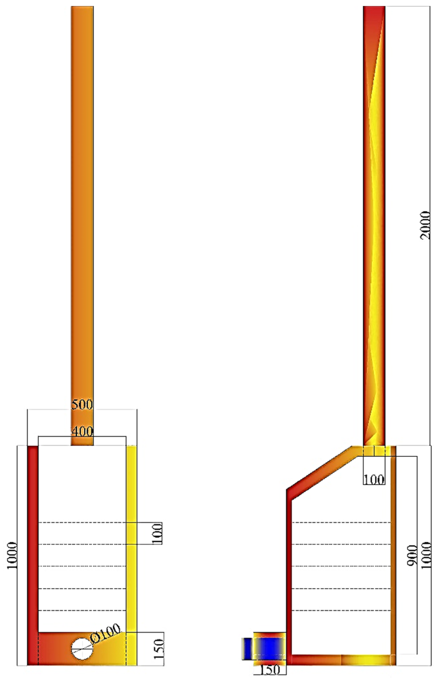
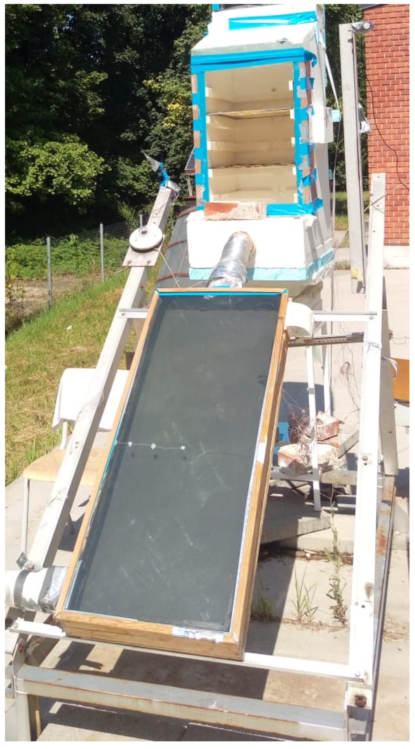
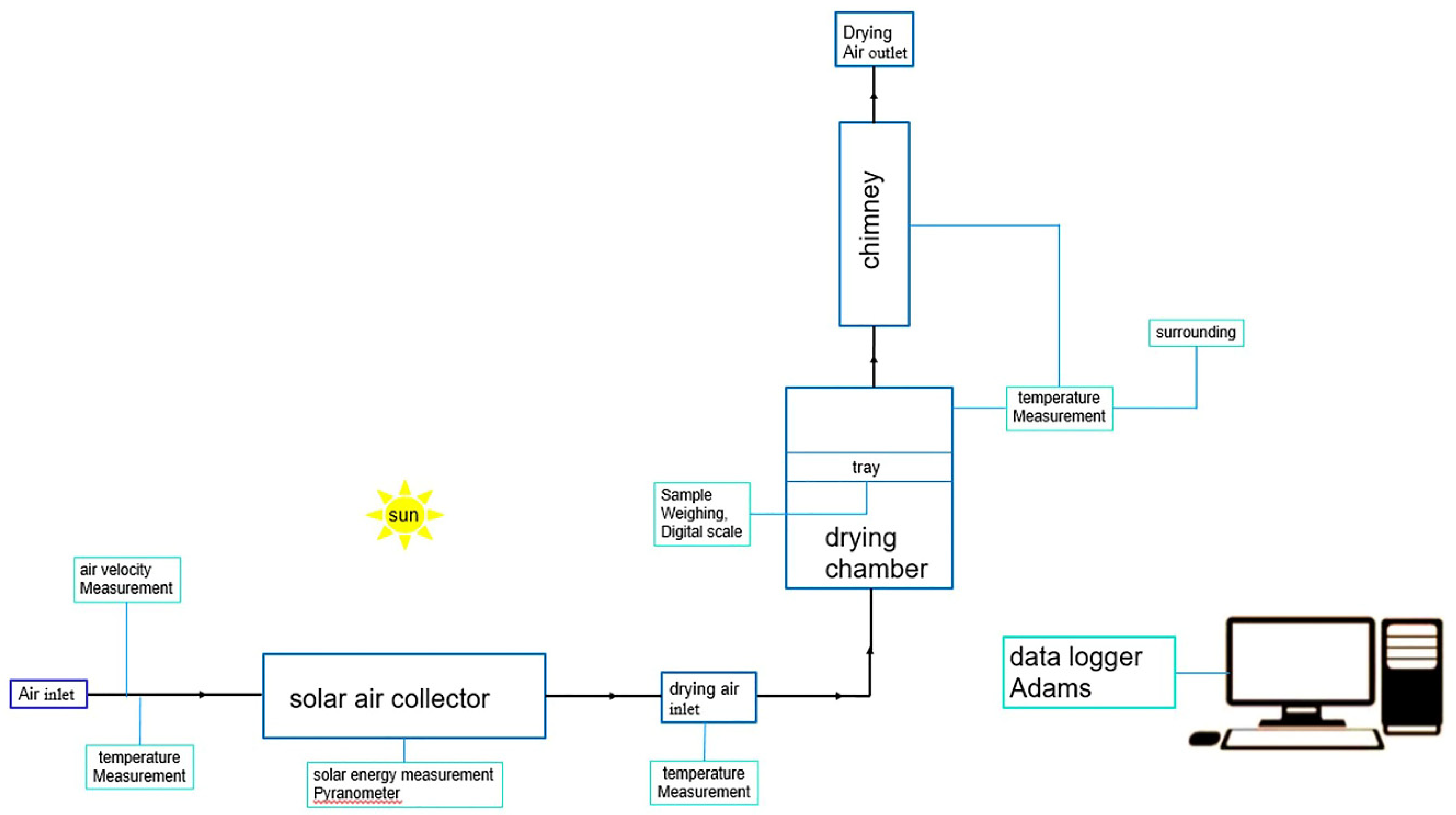
2.1. Experimental Set-Up

| Components | k (W·m−1·K−1) | C (kJ·kg−1·K−1) | αb | αd | τb | τd | ρb | ρd | ε |
|---|---|---|---|---|---|---|---|---|---|
| Plexiglass cover | 0.190 [25] | - | 0.080 | 0.079 | 0.887 | 0.940 | 0.050 | 0.052 | 0.78 [26] |
| Copper plate | 385 [27] | 387 [28] | 0.65 [27] | - | - | - | - | 0.95 | |
| Polystyrene | 0.130 [29] | - | - | - | - | - | - | - | - |
| Plywood | 0.038 [30] | - | - | - | - | - | - | - | - |
| Material | Dimensions | Thickness |
|---|---|---|
| Glass cover | 1160 × 460 mm2 | 4 mm |
| Plywood box | 1200 × 500 × 150 mm3 | 20 mm (side), 2 mm (bottom), 2 mm (reveals approx.) |
| Copper plate | 1160 × 460 mm2 | 1.2 mm |
| Polystyrene | 1160 × 460 mm2 | 80 mm |
| Air space | 1160 × 460 mm2 | 60 mm |
| PVC duct | 200 × 45 mm2 | 3.17 mm |


2.2. Performance Analysis of the Collector
3. Results and Discussion
4. Conclusions
- Natural draught would influence the momentum diffusivity of the airstream, which consequently impacts the heat removal factor.
- The transient flow of the airstream would bring less steadiness in the total energy line and the solar dryer would have peak pressure during noontime, whereas it would happen early in the day for the conventional dryer (without any auxiliary unit). Moreover, it pushed the system to the forced convection regime.
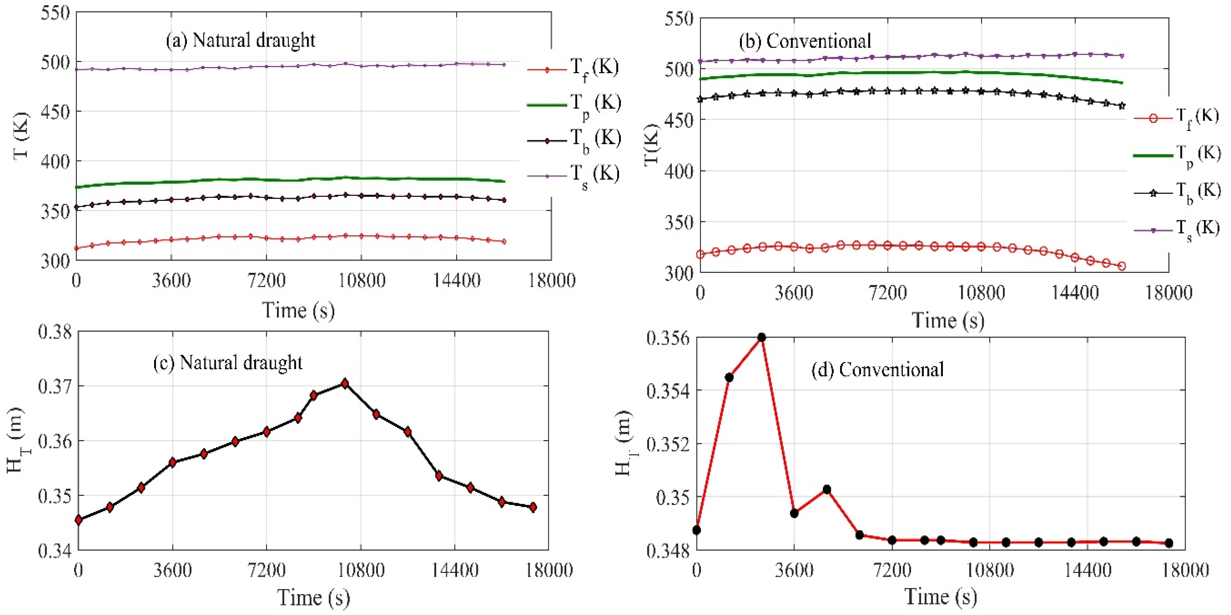
- The stagnant temperature of a solar collector with natural draught was reduced by 3.2% and the deviation between Ts and Tpm was relatively increased. Conversely, the deviation between Tfm and Tpm was reduced by 64.55%.
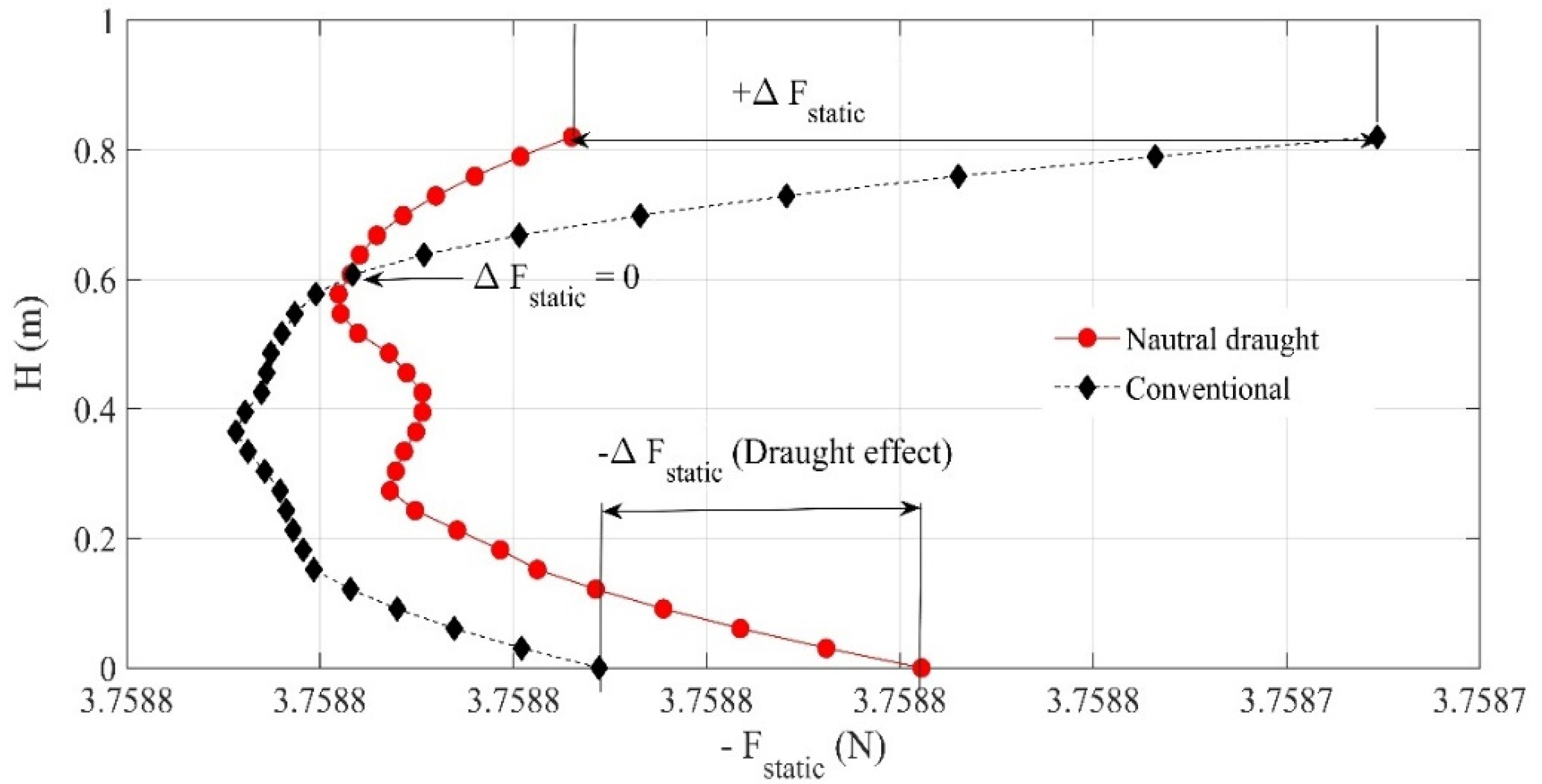
- The static pressure negligibly increased while running the solar collector with the natural draught unit.
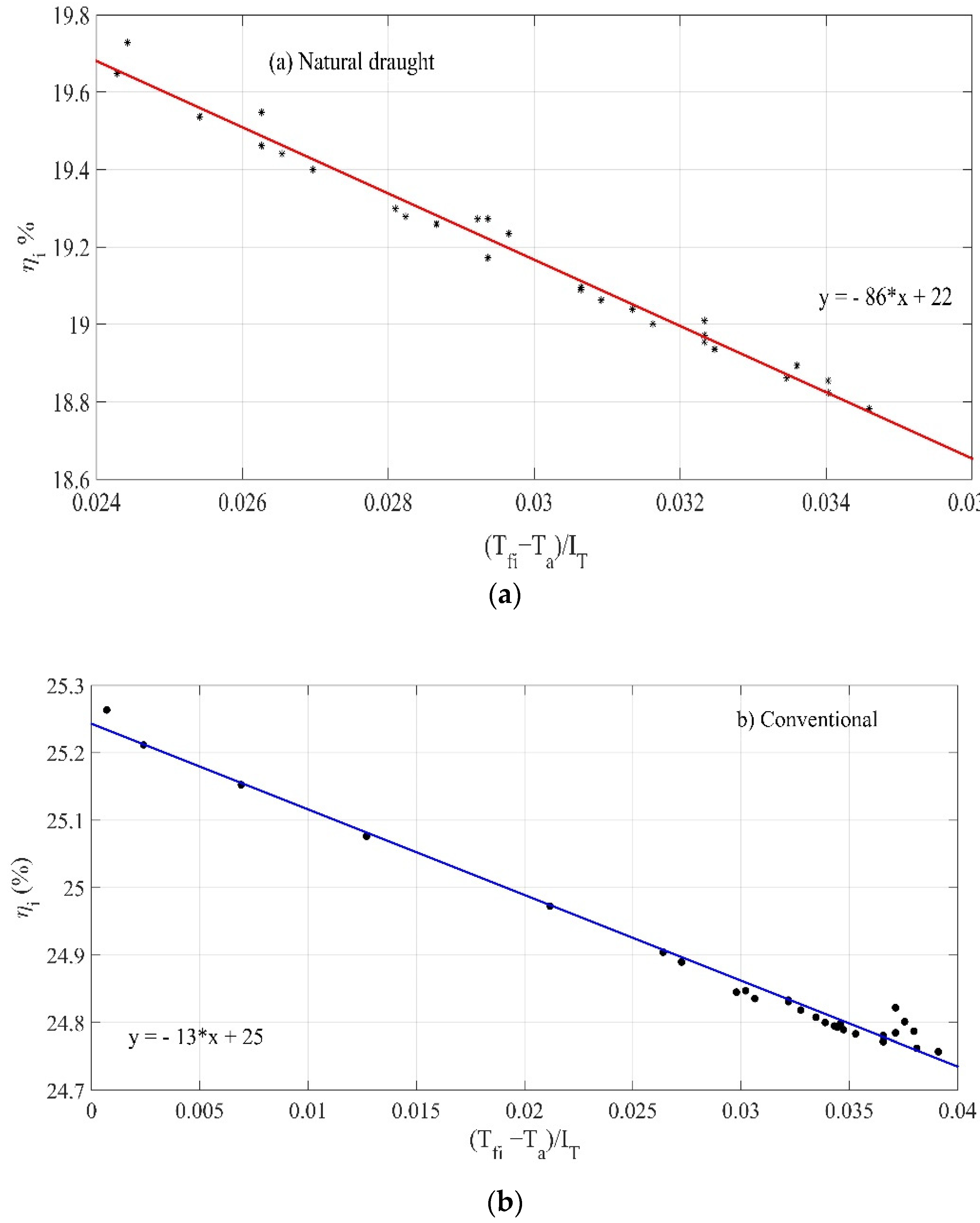
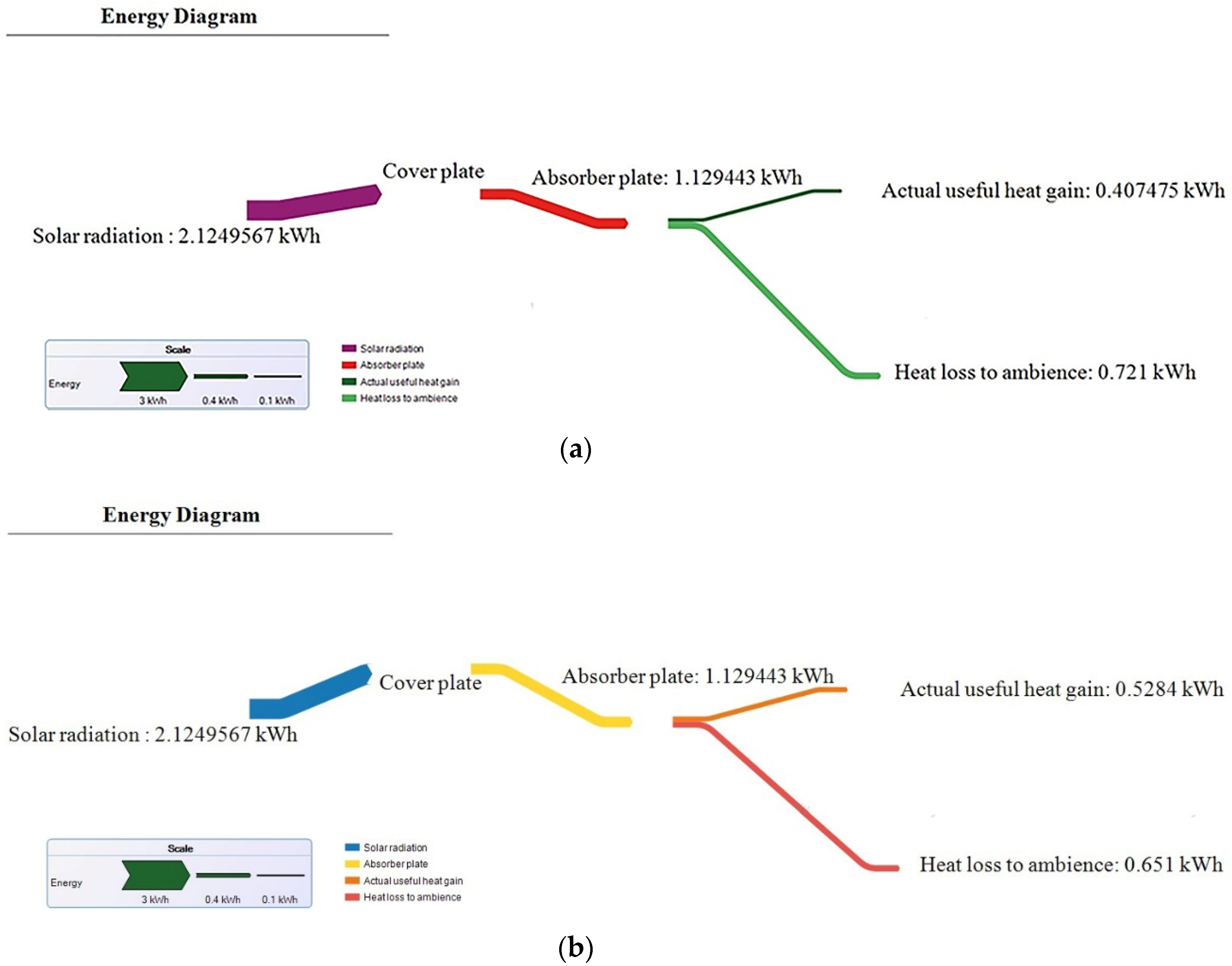
- The collector efficiency was reduced by 22.84% using the circular chimney.
- The overall losses were increased by 11% for the solar collector attached to the dryer operated with a chimney.
- The hydrostatic boundary layer would be impacted if the solar collector operated with a circular chimney.
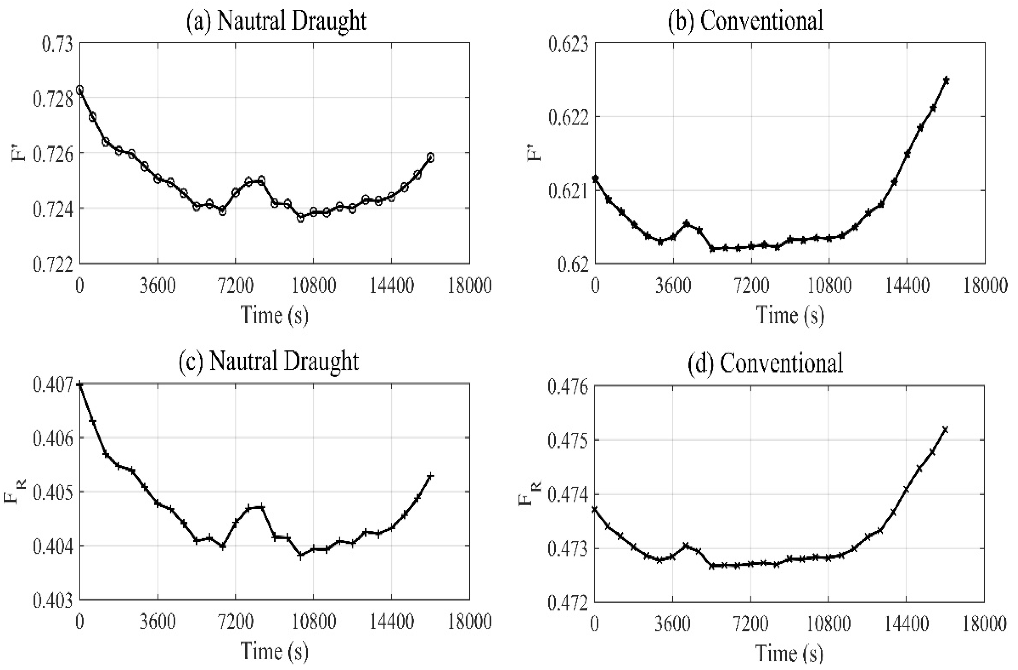
- The collector efficiency factor F′ increased by 16.58%, whereas the collector heat removal factor FR decreased by 14.37% for the same collector running with natural draught.
- The equivalent loss coefficient Ul was reduced by 89.61% without natural draught.
- The pressure drop was drastically increased while operating the solar collector with natural draught.
Author Contributions
Funding
Institutional Review Board Statement
Informed Consent Statement
Data Availability Statement
Conflicts of Interest
Abbreviations
| Symbol | Description | Unit |
| θ | Zenith angle | ° |
| δ | Declination angle | ° |
| ɸ | Latitude | ° |
| β | Angle of tilt | ° |
| ω | Hour angle | ° |
| rb | The tilt factor for beam radiation | - |
| rd | The tilt factor for diffuse radiation | - |
| rr | The tilt factor for reflected radiation | - |
| Ib | Hourly beam radiation | W·m−2 |
| Ig | Hourly global radiation | W·m−2 |
| Id | Hourly diffuse radiation | W·m−2 |
| S | The flux absorbed in the absorber plate | W·m−2 |
| I0 | Extra-terrestrial radiation | W·m−2 |
| Scs | Solar constant | W·m−2 |
| ρg | Ground reflectivity | - |
| ηi | The instantaneous collection efficiency | - |
| θ2 | Angle of refraction | ° |
| K | The extinction coefficient | m−1 |
| τ | Transmissivity of the cover plate | - |
| τr | Transmissivity based on reflection and refraction | - |
| τa | Transmissivity is derived by considering only absorption | - |
| ε | Emissivity | - |
| p, c | Subscript for plate and glazing cover | - |
| σ | Stefan–Boltzmann constant | W·m−2·K−4 |
| qu | Useful heat gain | W |
| ql | The rate at which heat is lost by convection and re-radiation from the top, and by conduction and convection from the bottom and sides. | W |
| Ac | The collector gross area | m2 |
| δc | The thickness of the cover plate | m |
| h | Subscript for horizontal surface | - |
| FR | Heat removal factor | - |
| F′ | Collector efficiency factor | - |
| Ap | Absorber plate area | m2 |
| Ul | The equivalent overall loss coefficient | W·m−2·K−1 |
| hfp | Heat transfer coefficient between air and plate | W·m−2·K−1 |
| hr | Equivalent radiative heat transfer coefficient | W·m−2·K−1 |
| he | The effective heat transfer coefficient between the absorber plate and airstream | W·m−2·K−1 |
| Tfi | The inlet temperature of the air | K |
| Ta | The temperature of the surrounding air | K |
| Tpm | The average temperature of the absorber plate | K |
| Tbm | The average temperature of the backplate | K |
| Tfm | The mean temperature of the air stream | K |
| Ts | The stagnation temperature of the absorber plate | K |
| hL | Pressure-drop in the duct | Pa |
| AM | Air Mass | - |
| Nu | Nusselt number | - |
| Re | Reynolds number | - |
| Le | Equivalent diameter | m |
| HT | Total pressure head at the outlet of the solar collector | m |
Appendix A
References
- Dutta, P.; Dutta, P.P.; Kalita, P.; Goswami, P.; Choudhury, P.K. Energy analysis of a mixed-mode corrugated aluminium alloy (AlMn1Cu) plate solar air heater. Mater. Today Proc. 2021, 47, 3352–3357. [Google Scholar] [CrossRef]
- Ural, T. Experimental performance assessment of a new flat-plate solar air collector having textile fabric as absorber using energy and exergy analyses. Energy 2019, 188, 116116. [Google Scholar] [CrossRef]
- Ammar, M.; Mokni, A.; Mhiri, H.; Bournot, P. Numerical analysis of solar air collector provided with rows of rectangular fins. Energy Rep. 2020, 6, 3412–3424. [Google Scholar] [CrossRef]
- Das, B.; Mondol, J.D.; Negi, S.; Smyth, M.; Pugsley, A. Experimental performance analysis of a novel sand coated and sand filled polycarbonate sheet based solar air collector. Renew. Energy 2020, 164, 990–1004. [Google Scholar] [CrossRef]
- Zulkifle, I.; Alwaeli, A.H.; Ruslan, M.H.; Ibarahim, Z.; Othman, M.Y.H.; Sopian, K. Numerical investigation of V-groove air-collector performance with changing cover in Bangi, Malaysia. Case Stud. Therm. Eng. 2018, 12, 587–599. [Google Scholar] [CrossRef]
- Heydari, A.; Mesgarpour, M. Experimental analysis and numerical modeling of solar air heater with helical flow path. Sol. Energy 2018, 162, 278–288. [Google Scholar] [CrossRef]
- Naphon, P.; Kornkumjayrit, K. Numerical analysis on the fluid flow and heat transfer in the channel with V-shaped wavy lower plate. Int. Commun. Heat Mass Transf. 2008, 35, 839–843. [Google Scholar] [CrossRef]
- Karim, M.; Hawlader, M. Performance investigation of flat plate, v-corrugated and finned air collectors. Energy 2006, 31, 452–470. [Google Scholar] [CrossRef]
- Sundén, B.; Sköldheden, T. Heat transfer and pressure drop in a new type of corrugated channels. Int. Commun. Heat Mass Transf. 1985, 12, 559–566. [Google Scholar] [CrossRef]
- Hernández, A.L.; Quiñonez, J.E. Analytical models of thermal performance of solar air heaters of double-parallel flow and double-pass counter flow. Renew. Energy 2013, 55, 380–391. [Google Scholar] [CrossRef]
- Natarajan, E.; Sathish, R. Role of nanofluids in solar water heater. Int. J. Adv. Manuf. Technol. 2009, 43, 746–757. [Google Scholar] [CrossRef]
- Farajzadeh, E.; Movahed, S.; Hosseini, R. Experimental and numerical investigations on the effect of Al2O3/TiO2H2O nanofluids on thermal efficiency of the flat plate solar collector. Renew. Energy 2017, 118, 122–130. [Google Scholar] [CrossRef]
- Winston, R. Principles of solar concentrators of a novel design. Sol. Energy 1974, 16, 89–95. [Google Scholar] [CrossRef]
- El-Sebaii, A.; Al-Snani, H. Effect of selective coating on thermal performance of flat plate solar air heaters. Energy 2010, 35, 1820–1828. [Google Scholar] [CrossRef]
- Dissa, A.; Ouoba, S.; Bathiebo, D.; Koulidiati, J. A study of a solar air collector with a mixed “porous” and “non-porous” composite absorber. Sol. Energy 2016, 129, 156–174. [Google Scholar] [CrossRef]
- Chaichan, M.T.; Abaas, K.I.; Kazem, H.A. Design and assessment of solar concentrator distillating system using phase change materials (PCM) suitable for desertic weathers. Desalination Water Treat. 2015, 57, 14897–14907. [Google Scholar] [CrossRef]
- Hans, V.; Saini, R.; Saini, J. Heat transfer and friction factor correlations for a solar air heater duct roughened artificially with multiple v-ribs. Sol. Energy 2010, 84, 898–911. [Google Scholar] [CrossRef]
- Sharma, S.; Kalamkar, V. Experimental and numerical investigation of forced convective heat transfer in solar air heater with thin ribs. Sol. Energy 2017, 147, 277–291. [Google Scholar] [CrossRef]
- Nowzari, R.; Aldabbagh, L.; Egelioglu, F. Single and double pass solar air heaters with partially perforated cover and packed mesh. Energy 2014, 73, 694–702. [Google Scholar] [CrossRef]
- Mohammadi, K.; Sabzpooshani, M. Comprehensive performance evaluation and parametric studies of single pass solar air heater with fins and baffles attached over the absorber plate. Energy 2013, 57, 741–750. [Google Scholar] [CrossRef]
- Koca, A.; Oztop, H.F.; Koyun, T.; Varol, Y. Energy and exergy analysis of a latent heat storage system with phase change material for a solar collector. Renew. Energy 2008, 33, 567–574. [Google Scholar] [CrossRef]
- Goering, D.; Humphrey, J.; Greif, R. The dual influence of curvature and buoyancy in fully developed tube flows. Int. J. Heat Mass Transf. 1997, 40, 2187–2199. [Google Scholar] [CrossRef]
- Dhaundiyal, A.; Atsu, D. The effect of thermo-fluid properties of air on the solar collector system. Alex. Eng. J. 2021, 61, 2825–2839. [Google Scholar] [CrossRef]
- Dhaundiyal, A.; Gebremicheal, G.H. The effect of psychrometry on the performance of a solar collector. Environ. Sci. Pollut. Res. 2021, 29, 13445–13458. [Google Scholar] [CrossRef]
- Plastic Properties. Available online: https://www.emcoplastics.com/assets/pdf/plexiglas/Plexiglas%20General%20Information%20and%20Properties.pdf (accessed on 10 November 2021).
- Zwinkels, J.C.; Davidson, W.F.; Dodd, C.X. Optical properties of UV transmitting acrylics for use in a heavy water Cerenkov detector. Appl. Opt. 1990, 29, 3240–3248. [Google Scholar] [CrossRef] [PubMed][Green Version]
- Carvill, J. Mechanical Engineer’s Data Handbook; Elsevier: Oxford, UK, 1993. [Google Scholar]
- Holman, J.P. Heat Transfer, 9th ed.; McGraw-Hill, Inc.: New York, NY, USA; Boston, MA, USA, 2002. [Google Scholar]
- Pelsmakers, S. The Environmental Design Pocketbook; RIBA Publishing: London, UK, 2019. [Google Scholar] [CrossRef]
- Billington, M.; Barnshaw, S.; Bright, K.; Crooks, A. The Building Regulations: Explained and Illustrated; John Wiley & Sons: Hoboken, NJ, USA, 2017. [Google Scholar]
- Dhaundiyal, A.; Gebremichael, G.H.; Atsu, D. Comprehensive Analysis of Solar Dryer with a Natural Draught. Energy Sources Part A Recovery Util. Environ. Eff. 2021. [Google Scholar] [CrossRef]
- Whillier, A. Performance of black-painted solar air heaters of conventional design. Sol. Energy 1964, 8, 31–37. [Google Scholar] [CrossRef]
- Kays, W.M. Convective Heat and Mass Transfer; McGraw-Hill Book Co.: New York, NY, USA, 1967. [Google Scholar]
- De Jong, J.B.R.M. Een Karakterisering van de Zonnestraling in Nederland; Doctoraalverslag: Eindhoven, The Netherlands, 1980. [Google Scholar]
- Rani, P.; Tripathy, P. Thermal characteristics of a flat plate solar collector: Influence of air mass flow rate and correlation analysis among process parameters. Sol. Energy 2020, 211, 464–477. [Google Scholar] [CrossRef]
- Garcia, R.P.; Oliveira, S.D.R.; Scalon, V.L. Thermal efficiency experimental evaluation of solar flat plate collectors when introducing convective barriers. Sol. Energy 2019, 182, 278–285. [Google Scholar] [CrossRef]


| Parameters | Natural Draught | Conventional |
|---|---|---|
| hfp (W·m−2·K−1) | 2.491 | 0.706 |
| Re | 2961.614 | 610.934 |
| Gr | 1.67 × 10⁸ | 7.37 × 10⁸ |
| Pr | 0.77 | 0.78 |
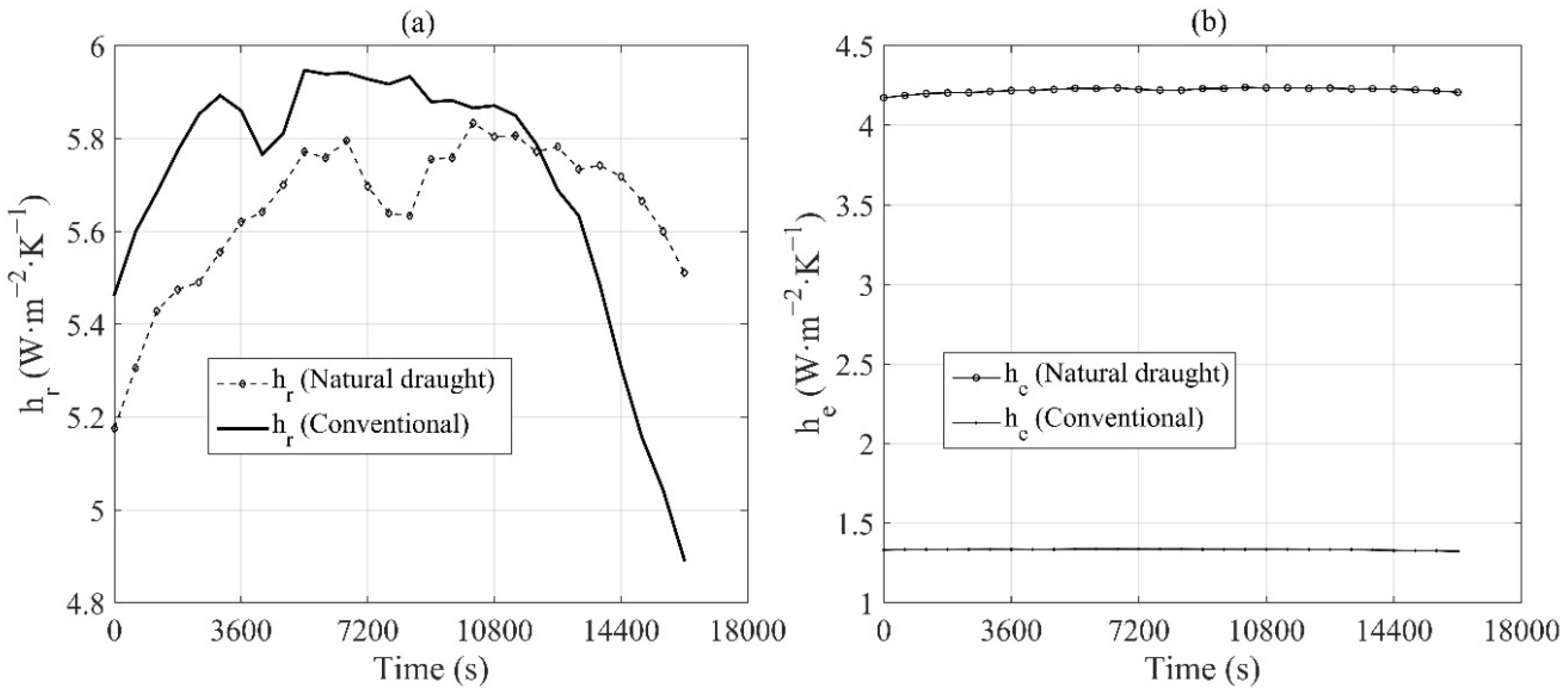
| hr (W·m−2·K−1) | 5.574 | 5.625 |
| he (W·m−2·K−1) | 4.210 | 1.334 |
| FR | 0.405 | 0.473 |
| F′ | 0.724 | 0.621 |
| Fstatic (N) | 3.758 | 3.758 |
| Ul (W·m−2·K−1) | 2.128 | 0.221 |
| qu (W) | 81.495 | 105.680 |
| hL(Pa) | 0.058 | 0.004 |
| Ut (W·m−2·K−1) | 2.0805 | 0.669 |
| Ub (W·m−2·K−1) | 0.318 | 0.240 |
| ql (W) | 144.393 | 130.208 |
| % | 19.180% | 24.860% |
| Tpm (K) | 380.130 | 488.182 |
| Tbm (K) | 362.118 | 474.788 |
| Tfm (K) | 321.310 | 322.25 |
| Ts (K) | 494.648 | 511.036 |
| HT (m) | 0.355 | 0.350 |
| S0(W·m−2) | 809.570 | |
| AM | 1.703 | |
| 11 | ||
| f | 0.0107 | 0.016 |
Publisher’s Note: MDPI stays neutral with regard to jurisdictional claims in published maps and institutional affiliations. |
© 2022 by the authors. Licensee MDPI, Basel, Switzerland. This article is an open access article distributed under the terms and conditions of the Creative Commons Attribution (CC BY) license (https://creativecommons.org/licenses/by/4.0/).
Share and Cite
Dhaundiyal, A.; Gebremicheal, G.H. The Stack Effect on the Thermal-Fluid Behaviour of a Solar Collector. Energies 2022, 15, 1188. https://doi.org/10.3390/en15031188
Dhaundiyal A, Gebremicheal GH. The Stack Effect on the Thermal-Fluid Behaviour of a Solar Collector. Energies. 2022; 15(3):1188. https://doi.org/10.3390/en15031188
Chicago/Turabian StyleDhaundiyal, Alok, and Gedion Habtay Gebremicheal. 2022. "The Stack Effect on the Thermal-Fluid Behaviour of a Solar Collector" Energies 15, no. 3: 1188. https://doi.org/10.3390/en15031188
APA StyleDhaundiyal, A., & Gebremicheal, G. H. (2022). The Stack Effect on the Thermal-Fluid Behaviour of a Solar Collector. Energies, 15(3), 1188. https://doi.org/10.3390/en15031188