Article

Design and Implementation of a Dual-Band Filtering Wilkinson Power Divider Using Coupled T-Shaped Dual-Band Resonators

by
Sobhan Roshani
1,
Slawomir Koziel
2,3,
Saeed Roshani
1,*,
Faezeh Sadat Hashemi Mehr
1 and
Stanislaw Szczepanski
3
1
Department of Electrical Engineering, Kermanshah Branch, Islamic Azad University, Kermanshah 6718997551, Iran
2
Department of Engineering, Reykjavik University, 102 Reykjavik, Iceland
3
Faculty of Electronics, Telecommunications and Informatics, Gdansk University of Technology, 80-233 Gdansk, Poland
*
Author to whom correspondence should be addressed.
Energies 2022, 15(3), 1189; https://doi.org/10.3390/en15031189
Submission received: 11 January 2022 / Revised: 1 February 2022 / Accepted: 3 February 2022 / Published: 6 February 2022
(This article belongs to the Special Issue RF/Microwave Circuit Design and Characterization Techniques)

Abstract

:
The paper introduces a novel structure of a dual-band filtering Wilkinson power divider (WPD). Its essential component is a dual-band bandpass filter (BPF), implemented using coupling lines and two T-shaped resonators. The BPF is incorporated into the divider structure to suppress the unwanted harmonics within the circuit. The latter is achieved owing to a wide stopband of the filter. The designed dual-band WPD can suppress third unwanted harmonics in both channels with high levels of attenuation. The designed dual-band WPD operates at 2.6 GHz and 3.3 GHz with a return loss of 22.1 dB and 22.3 dB at the operating frequencies. Furthermore, the insertion loss and isolation are 0.3 dB and 20.2 dB at 2.6 GHz and 0.9 dB and 24.5 dB at 3.3 GHz. The analysis and simulation results are corroborated by the measurements of the fabricated divider prototype. The competitive performance of the proposed circuit is also demonstrated through comparisons with state-of-the-art divider circuits from the literature.

1. Introduction

Power dividers belong to the class of important microwave components, widely used in microwave and communication circuits such as amplifiers [1,2,3,4] and antenna feeding networks [5,6,7,8,9,10,11].
Recently, with the development of multiband microwave communication systems, the demands for multiband devices, including power dividers, has been continuously increasing [12,13,14]. Numerous dual-band divider circuits have been proposed and studied in the literature. These can be categorized into several groups, distinguished by the specific implementation technique employed to design a circuit. The major methods, recently used to realize dual-band power dividers, include incorporation of two-section transformers [12,15,16], open/short-ended stubs [17,18,19], defected ground structures [20,21,22], resonators [23,24,25,26,27,28], coupled lines [29,30,31,32], and lumped elements [33,34].
Another technique to design of dual-band dividers is utilization of two-section transformers combined with open/short-ended stubs [12,14,15,16,17,18,19]. Although using two-section transformers may enable dual-band operation, harmonic suppression becomes a problem. At the same time, the circuits feature excessive physical size. In [18], a tri-band Gysel power divider is presented based on open stubs, coupled lines, and slow-wave transmission line techniques. In this circuit, the harmonic suppression is obtained; however, the output port isolation is insufficient in some of the operating bands. In [19], a dual-band filtering divider is presented by applying short-ended stubs at the divider’s main branch, forming a T-junction structure. Although this divider implements dual-band operation, neither harmonic suppression nor size reduction have been achieved [19].
In [20,21,22], a defected ground technique is employed in the design of multi-band dividers. For example, a divider designed in [20] uses a defected ground structure and folded slot lines to realize dual-band operation. Furthermore, the circuit of [20] employs band-pass filter (BPF) cells to obtain harmonic suppression. On the other hand, the data reported in the mentioned paper indicates poor passband insertion loss. It should also be emphasized that defected ground methods contribute to fabrication complexity by adding an extra metallization layer. Additionally, the crystal photonic substrates which are useful for higher frequencies [35,36,37,38,39,40,41,42,43] have recently employed for power divider designs [44,45]
Currently, dual-band dividers are more frequently implemented with the aid of resonators, which facilitates size reduction and harmonic suppression [23,24,25,26,27,28]. Notwithstanding, improper utilization of this technique may result in high insertion loss, low isolation, and complex structure. Several types of resonators have been be used in divider design such as patch resonators [23], substrate integrated waveguide resonators [24], dual-composite resonators [25], stepped impedance resonators [26], and ring resonators [27]. Another technique is utilization of coupled lines, which can be incorporated into the divider structure to realize dual- or multi-band operation [29,30,31,32]. This method can also be employed to achieve broadband performance, but it may also increase the insertion loss in the passband.
Yet, another method to enable multi-band operation along with size reduction and implementation of filtering properties of power dividers is the incorporation of lumped elements [33,34]. However, lumped components may be detrimental to divider performance due to the parasitic effects that occur at higher frequencies.
In practical design, the development of a divider architecture and topology has to be accompanied by tuning of geometry parameters. While circuit-theory-based methods typically yield reasonably good initial parameter values, more often than not, these have to be further adjusted to boost the circuit performance as much as possible. In terms of algorithmic approaches [46,47,48,49,50,51,52,53,54], on the top of conventional (e.g., gradient-based) techniques, artificial intelligence methods [55,56,57,58,59,60,61,62,63,64,65]—which have been widely used to solve a variety of engineering problems [66,67,68,69,70,71,72,73,74,75]—can also be employed to model and design power dividers [76,77].
The aim of this research is to demonstrate the usefulness of incorporating T-shaped resonators and coupled lines in the development of dual-band WPDs. The specific divider structure proposed in the paper is designed to operate at 2.6 GHz and 3.3 GHz. An important component of the circuit is a dual-band filter, implemented to ensure suppression of the unwanted harmonics. Simulation and measurement data indicate superior performance of the presented circuit in terms of return and insertion losses, port isolation, as well as harmonic cancellation, which make it competitive over state-of-the-art divider structures reported in the literature.

2. Basic Dual-Band Filter Design

The design procedure of the basic dual-band filter is described in this section. Therein, a prototype of a three-pole Butterworth low pass filter (LPF) is selected as the fundamental circuit for the dual-band filter.

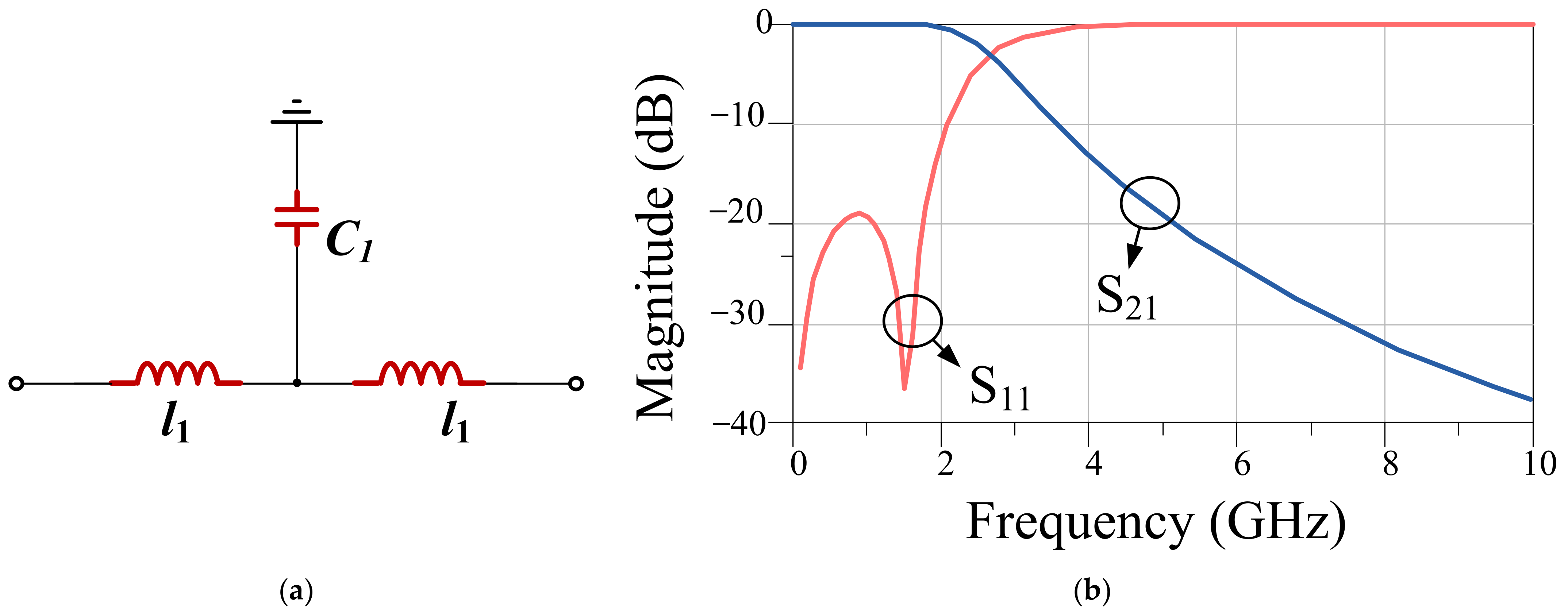
2.1. The Three-Pole Butterworth Low-Pass Filter (LPF)

The prototype of a three-pole Butterworth LPF schematic and its simulated S-parameters are depicted in Figure 1. It can be observed that the three-pole Butterworth LPF transition band is not sufficiently sharp; additionally, dual-band operation cannot be realized with this structure. The cutoff frequency and bandwidth (BW) of the LPF can be determined as
BW = f C = 1 π 2 l 1 C 1
To improve the performance of the three-pole Butterworth LPF, a new resonator is incorporated into the filter structure, which will be discussed in the next section.

2.2. Basic LPF Prototype

The prototype of the basic LPF and its simulated S-parameters are depicted in Figure 2. As seen, the transition band and the suppression band are improved over the structure of Section 2.1. The resonator marked as Part2, as indicated in Figure 2, realizes the transmission zero at 4 GHz. The frequency of the transmission zero can be modified by adjusting the resonator element values. To calculate the frequency of the transmission zero, the input impedance Zin-RP2 of the filter must be extracted. It can be written as
Z i n R P 2 = j l 2 ω + Z i n 3 / 2
By substituting the impedance Zin3 of l3C3 resonator branch, the filter input impedance can be expressed as
Z i n R P 2 = j ω 2 2 l 2 C 3 + l 3 C 3 1 2 C 3 ω
The resonance condition will be satisfied, when the imaginary part of Zin becomes zero. Consequently, the resonant frequency of the basic LPF can be found as
f T Z = 1 2 π 2 l 2 C 3 + l 3 C 3
The resonator marked as Part 1, also indicated in Figure 2, controls the pole frequencies, and the suppression band attenuation level in the low pass filter.

2.3. Basic Dual-Band Filter

The prototype of the proposed basic dual-band filter and its simulated S-parameters are depicted in Figure 3. The filter realizes dual-band operation by adding extra poles, created by incorporating extra capacitances into the basic low-pass filter circuit. The relevance of these modifications has been demonstrated in Figure 3b by showing the two aforementioned poles visible in the simulated reflection response of the device. The values of lumped elements, used in the discussed resonators and filters, explained in Section 2, have been gathered in Table 1.

3. Dual-Band Filter: Layout Design

Realization of a satisfactory suppression band in the dual-band power divider requires the design of a dual-band filter. Section 2 discussed a basic dual-band filter architecture. In this section, the transmission line realization of the filter, which will be referred to as a dual-band T-shaped resonator, is described.

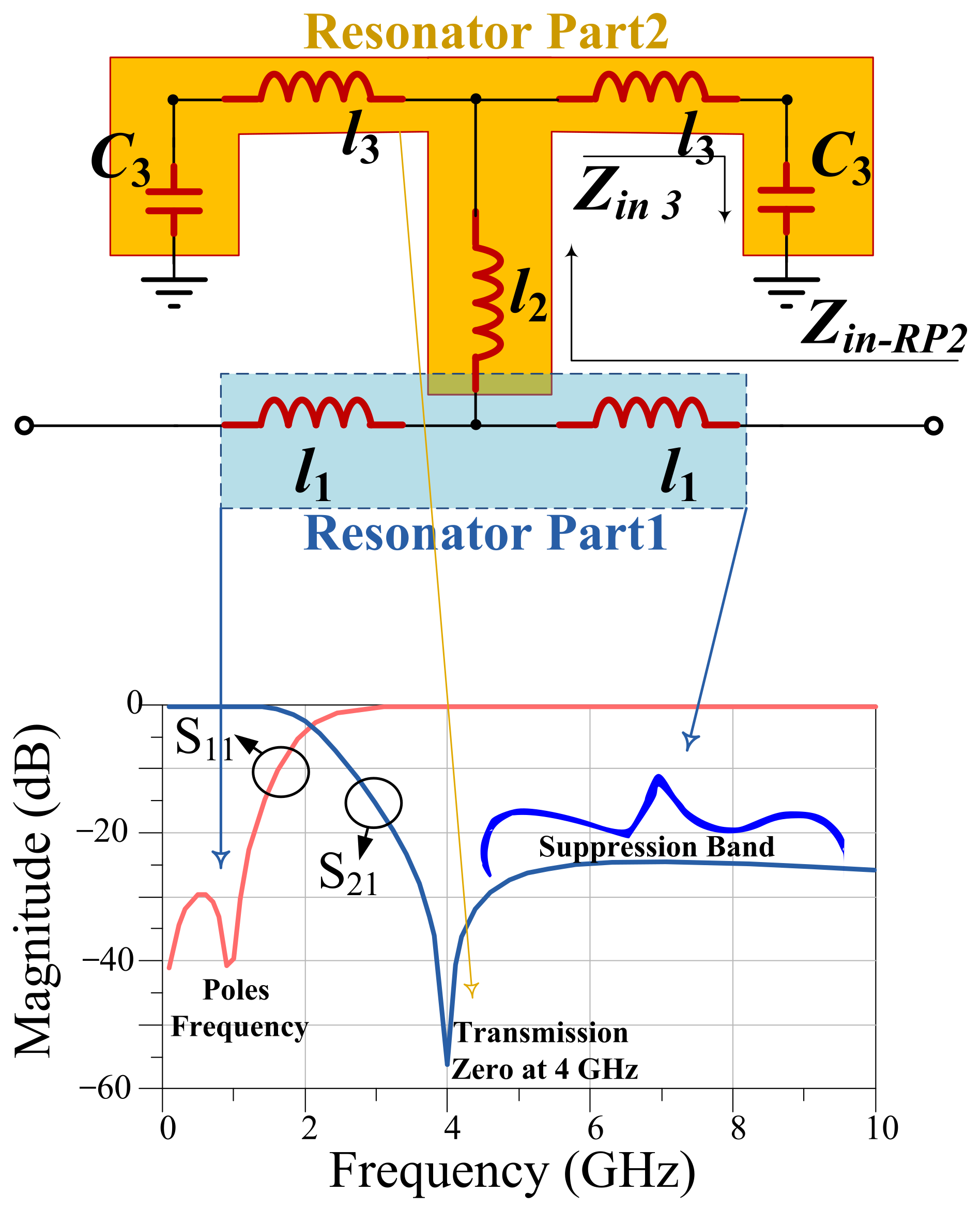
3.1. Dual-Band T-Shaped Resonator Design

The T-shaped resonator is selected as the basic structure of the proposed power divider, because of its desirable performance and compact size. The layout and the simulated S-parameters of the dual-band T-shaped resonator have been shown in Figure 4. The resonator frequency response contains three transmission zeroes and two poles. The pole location can be adjusted to modify the dual-band operation as needed.

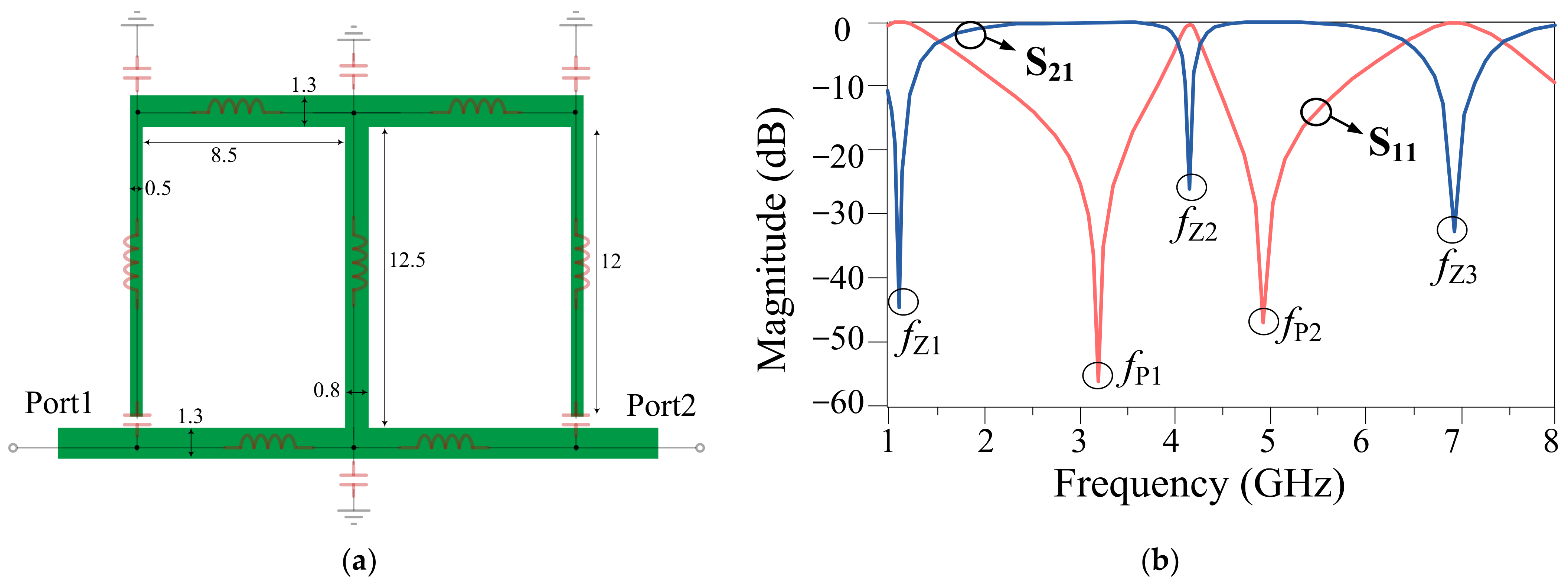
3.2. Final Dual-Band Filter Design

The layout and the simulated S-parameters of the proposed final dual-band filter have been shown in Figure 5. The final circuit is formed by adding the coupled lines to the dual-band T-shaped resonator. In the proposed filter, the bandwidth of the bandpass channels can be modified by adding the coupled lines to achieve the desired frequency response.
By adding the coupled lines into the proposed dual-band T-shaped resonator, the poles’ frequencies, which were located at fP1 = 3.2 GHz and fP2 = 4.9 GHz are changed to the desired frequencies of fP1_New = 3.1 GHz and fP2_New = 5.2 GHz in the proposed final dual-band filter. Additionally, adding the coupled lines into the proposed dual-band T-shaped resonator have led to about 0.1 dB improvement of the insertion loss parameter for the both channels in the proposed final filter. In the proposed final dual-band filter, the two poles, created at 3.1 GHz and 5.2 GHz, provide two desired operating channels for the filter. Subsequently, the obtained dual-band filter can be incorporated in the power divider structure to obtain dual operating bands. The 3 dB obtained bandwidth of the first passband channel is from 2.8 GHz and 3.4 GHz, whereas the bandwidth of the second passband channel is from 4.9 GHz and 5.5 GHz. Thus, the bandwidth at both passband channels is 600 MHz. The insertion loss |S21| and the return loss |S11| at first operating frequency (3.1 GHz) are 0.1 dB and 39 dB, respectively, whereas |S21| and |S11| at second operating frequency (5.2 GHz) are 0.3 dB and 25 dB, respectively.

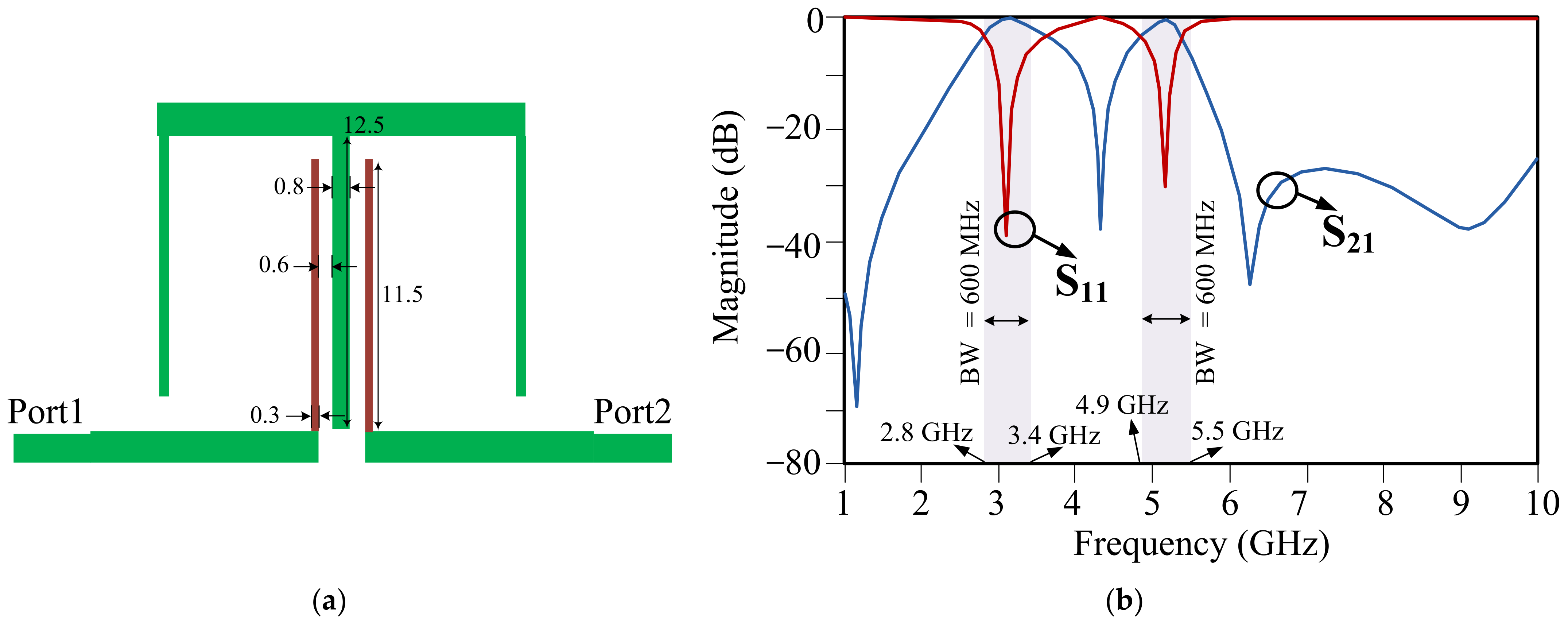
4. The Proposed Power Divider Results

The layout and the picture of the fabricated prototype of the proposed dual-band WPD have been shown in Figure 6. As explained in Section 2 and Section 3, a dual-band filter is first designed and analyzed. Subsequently, the main branch lines of the power divider are replaced with the proposed filter to achieve the designed dual-band WPD. The lumped 100 Ω resistor is added between port 2 and port 3 to ensure sufficient port isolation. The current distributions of the presented divider at the two main operating frequencies and the two transmission zero frequencies are shown in Figure 7. As seen, the high-magnitude current is observed within the divider at the two main frequencies, while it is reduced at the transmission zero frequencies.
The S-parameters of the designed dual-band WPD have been shown in Figure 8. The measured values of S-parameters at the first operating frequency of 2.6 GHz are |S21| = 4.2 dB, |S11| = 13.5 dB, |S22| = 14.1 dB, and |S23| = 12.2 dB, whereas the measured S-parameter values at the second operating frequency of 3.3 GHz are |S21| = 4.1 dB, |S11| = 16 dB, |S22| = 11.5 dB, and |S23| = 12.8 dB. The operating bandwidths achieved for the circuit are 2.55 GHz to 2.81 GHz (first operating channel), and 3.18 GHz to 3.38 GHz (second operating channel).
The size of the proposed WPD is 19.2 mm × 31.3 mm or 0.27 λg × 0.44 λg, where λg = 70.5 mm corresponds to the guided wavelength at the frequency of 2.6 GHz. Figure 9 shows the measured and simulated |S21| of the divider evaluated over the broad frequency range. It can be observed that the third harmonics rejection has been achieved for both operating frequencies. The third harmonic of the first frequency, 3f1, is rejected with –46 dB level, whereas the third harmonic of the second frequency, 3f2, is suppressed by more than 25 dB.
A comparison between the performance of the designed dual-band WPD, and recent state-of-the-art dividers has been provided in Table 2. Based on the data analysis, it can be concluded that the proposed dual-band divider, apart from providing dual-band operation and harmonic suppression, has a competitive edge over the benchmark structures in terms of its physical size. Consequently, it may offer an alternative over existing circuits, especially for size-limited applications.
One of the distinctive features of the proposed circuit is the ability to suppress the third harmonic, which is an important undesirable harmonic in microwave components (while passed through the system channels may lead to considerable response degradation). The divider presented in this work offers a high level of attenuation thereof. This is in contrast to the benchmark structures reported in Table 2, the majority of which do not realize the filtering response at the third harmonic.

5. Conclusions

In this paper, a dual-band Wilkinson power divider with new and simple structure is proposed. The presented circuit incorporates a custom-designed dual-band bandpass filter for the purpose of harmonic suppression in both operating channels. A detailed design procedure and analysis has been provided to facilitate the parameter adjustment. The performance of the divider has been validated through full-wave EM simulations and physical measurements of the fabricated circuit prototype. A comprehensive comparison with the recent dividers reported in the literature corroborates the advantages of the proposed structure in terms of its overall utility (dual-band operation, harmonic suppression) but also small size. The latter makes our design potentially attractive for space-limited applications.

Author Contributions

Conceptualization, S.R. (Sobhan Roshani), S.K. and S.R. (Saeed Roshani); methodology, S.R. (Sobhan Roshani), F.S.H.M. and S.R. (Saeed Roshani); software, F.S.H.M. and S.R. (Saeed Roshani); validation, S.S.; formal analysis, S.S. and S.R. (Saeed Roshani); investigation, S.R. (Saeed Roshani); resources, S.R. (Sobhan Roshani) and F.S.H.M.; writing—original draft preparation, S.S. and S.R. (Saeed Roshani); writing—review and editing, S.R. (Sobhan Roshani) and S.S.; visualization, S.R. (Saeed Roshani), and S.S.; supervision, S.R. (Saeed Roshani); project administration. All authors have read and agreed to the published version of the manuscript.

Funding

This work was supported in part by the Icelandic Centre for Research (RANNIS) Grant 217771, and by National Science Centre of Poland Grant 2 020/37/B/ST7/0144.

Data Availability Statement

The data in the current work are available from the corresponding author on reasonable request.

Conflicts of Interest

The authors declare no conflict of interest regarding this article.

References

  1. Sakata, S.; Komatsuzaki, Y.; Shinjo, S. Adaptive Input-Power Distribution in Doherty Power Amplifier Using Modified Wilkinson Power Divider. In Proceedings of the 2020 IEEE Topical Conference on RF/Microwave Power Amplifiers for Radio and Wireless Applications (PAWR), San Antonio, TX, USA, 26–29 January 2020; pp. 34–37. [Google Scholar]
  2. Jamshidi, M.B.; Roshani, S.; Talla, J.; Roshani, S.; Peroutka, Z. Size Reduction and Performance Improvement of a Microstrip Wilkinson Power Divider Using a Hybrid Design Technique. Sci. Rep. 2021, 11, 7773. [Google Scholar] [CrossRef]
  3. Pirasteh, A.; Roshani, S.; Roshani, S. A Modified Class-F Power Amplifier with Miniaturized Harmonic Control Circuit. AEU Int. J. Electron. Commun. 2018, 97, 202–209. [Google Scholar] [CrossRef]
  4. Roshani, S.; Roshani, S. Design of a High Efficiency Class-F Power Amplifier with Large Signal and Small Signal Measurements. Measurement 2020, 149, 106991. [Google Scholar] [CrossRef]
  5. Chu, Q.-X.; Lin, W.; Lin, W.-X.; Pan, Z.-K. Assembled Dual-Band Broadband Quadrifilar Helix Antennas with Compact Power Divider Networks for CNSS Application. IEEE Trans. Antennas Propag. 2012, 61, 516–523. [Google Scholar] [CrossRef]
  6. Ullah, U.; Al-Hasan, M.; Koziel, S.; Mabrouk, I.B. A Series Inclined Slot-Fed Circularly Polarized Antenna for 5G 28 GHz Applications. IEEE Antennas Wirel. Propag. Lett. 2021, 20, 351–355. [Google Scholar] [CrossRef]
  7. Ullah, U.; Koziel, S. A Broadband Circularly Polarized Wide-Slot antenna with a Miniaturized Footprint. IEEE Antennas Wirel. Propag. Lett. 2018, 17, 2454–2458. [Google Scholar] [CrossRef]
  8. Ullah, U.; Koziel, S. A Geometrically Simple Compact Wideband Circularly Polarized Antenna. IEEE Antennas Wirel. Propag. Lett. 2019, 18, 1179–1183. [Google Scholar] [CrossRef]
  9. Ullah, U.; Koziel, S.; Mabrouk, I.B. Rapid Redesign and Bandwidth/Size Tradeoffs for Compact Wideband Circular Polarization Antennas Using Inverse Surrogates and Fast EM-Based Parameter Tuning. IEEE Trans. Antennas Propag. 2019, 68, 81–89. [Google Scholar] [CrossRef]
  10. Koziel, S.; Ogurtsov, S. Simulation-Based Optimization of Antenna Arrays; World Scientific: Singapore, 2019. [Google Scholar]
  11. Ogurtsov, S.; Koziel, S. Systematic Approach to Sidelobe Reduction in Linear Antenna Arrays through Corporate-Feed-Controlled Excitation. IET Microw. Antennas Propag. 2017, 11, 779–786. [Google Scholar] [CrossRef]
  12. Cheng, K.-K.M.; Wong, F.-L. A New Wilkinson Power Divider Design for Dual Band Application. IEEE Microw. Wirel. Components Lett. 2007, 17, 664–666. [Google Scholar] [CrossRef]
  13. Maktoomi, M.A.; Hashmi, M. A Performance Enhanced Port Extended Dual-Band Wilkinson Power Divider. IEEE Access 2017, 5, 11832–11840. [Google Scholar] [CrossRef]
  14. Park, M.-J.; Lee, B. A Dual-Band Wilkinson Power Divider. IEEE Microw. Wirel. Compon. Lett. 2008, 18, 85–87. [Google Scholar] [CrossRef]
  15. Monzon, C. A Small Dual-Frequency Transformer in Two Sections. IEEE Trans. Microw. Theory Tech. 2003, 51, 1157–1161. [Google Scholar] [CrossRef]
  16. Cheng, K.-K.M.; Law, C. A Novel Approach to the Design and Implementation of Dual-Band Power Divider. IEEE Trans. Microw. Theory Tech. 2008, 56, 487–492. [Google Scholar] [CrossRef]
  17. Wu, Y.; Liu, Y.; Zhang, Y.; Gao, J.; Zhou, H. A Dual Band Unequal Wilkinson Power Divider without Reactive Components. IEEE Trans. Microw. Theory Tech. 2009, 57, 216–222. [Google Scholar] [CrossRef]
  18. Liu, F.-X.; Wang, Y.; Zhang, X.-Y.; Quan, C.-H.; Lee, J.-C. A Size-Reduced Tri-Band Gysel Power Divider with Ultra-Wideband Harmonics Suppression Performance. IEEE Access 2018, 6, 34198–34205. [Google Scholar] [CrossRef]
  19. Shao, C.; Li, Y.; Chen, J.X. Compact Dual-Band Microstrip Filtering Power Divider Using T-Junction Structure and Quarter-Wavelength SIR. Electron. Lett. 2017, 53, 434–436. [Google Scholar] [CrossRef]
  20. Rao, Y.; Qian, H.J.; Yang, B.; Gomez-Garcia, R.; Luo, X. Dual-Band Bandpass Filter and Filtering Power Divider with Ultra-Wide Upper Stopband Using Hybrid Microstrip/DGS Dual-Resonance Cells. IEEE Access 2020, 8, 23624–23637. [Google Scholar] [CrossRef]
  21. Bai, Y.-F.; Wang, X.-H.; Shi, X.-W.; Lin, H.-J.; Chen, X.-Q.; Li, P. Design of Compact Planar Three-Way Dual-Band Power Divider Using Defected Ground Structure. In Proceedings of the 2010 International Conference on Microwave and Millimeter Wave Technology, Chengdu, China, 8–11 May 2010; pp. 70–73. [Google Scholar]
  22. Hedayati, M.K.; Moradi, G.; Abdipour, A.; Mosalanejad, M. A Miniaturized Dual-Frequency Wilkinson Power Divider Using Defected Ground Structure. In Proceedings of the 2010 IEEE Asia-Pacific Conference on Applied Electromagnetics (APACE), Port Dickson, Malaysia, 9–11 November 2010; pp. 1–5. [Google Scholar]
  23. Dong, G.; Wang, W.; Wu, Y.; Liu, Y.; Fang, Y.; Tentzeris, M.M. Compact Dual-Band Filtering Power Divider with Independently Controllable Bandwidths Using Shorted Patch Resonators. IET Microw. Antennas Propag. 2020, 14, 759–767. [Google Scholar] [CrossRef]
  24. Song, K.; Luo, M.; Yao, J.; Zhou, Y. Dual-Passband Bandpass-Filtering Power Divider Using Half-Mode Substrate Integrated Waveguide Resonator with High Frequency Selectivity. Int. J. RF Microw. Comput.-Aided Eng. 2020, 30, e22309. [Google Scholar] [CrossRef]
  25. Huang, T.; Feng, L.; Geng, L.; Liu, H.; Zheng, S.Y.; Ye, S.; Zhang, L.; Xu, H. Compact Dual-Band Wilkinson Power Divider Design Using Via-Free D-CRLH Resonators for Beidou Navigation Satellite System. IEEE Trans. Circuits Syst. II Express Briefs 2021, 69, 65–69. [Google Scholar] [CrossRef]
  26. Avrillon, S.; Pele, I.; Chousseaud, A.; Toutain, S. Dual-Band Power Divider Based on Semiloop Stepped-Impedance Resonators. IEEE Trans. Microw. Theory Tech. 2003, 51, 1269–1273. [Google Scholar] [CrossRef]
  27. Feng, W.; Hong, M.; Che, W. Dual-Band Balanced-to-Unbalanced Filtering Power Divider by Coupled Ring Resonators. Electron. Lett. 2016, 52, 1862–1864. [Google Scholar] [CrossRef]
  28. Chen, L.; Wei, F.; Cheng, X.Y.; Xiao, Q.K. A Dual-Band Balanced-to-Balanced Power Divider with High Selectivity and Wide Stopband. IEEE Access 2019, 7, 40114–40119. [Google Scholar] [CrossRef]
  29. Maktoomi, M.H.; Banerjee, D.; Hashmi, M.S. An Enhanced Frequency-Ratio Coupled-Line Dual-Frequency Wilkinson Power Divider. IEEE Trans. Circuits Syst. II Express Briefs 2017, 65, 888–892. [Google Scholar] [CrossRef]
  30. Feng, T.; Ma, K.; Wang, Y. A Dual-Band Coupled Line Power Divider Using SISL Technology. IEEE Trans. Circuits Syst. II Express Briefs 2020, 68, 657–661. [Google Scholar] [CrossRef]
  31. Lu, Y.; Dai, G.; Wang, Y.; Liu, T.; Huang, J. Dual-Band Filtering Power Divider with Capacitor-Loaded Centrally Coupled-Line Resonators. IET Microw. Antennas Propag. 2017, 11, 36–41. [Google Scholar] [CrossRef]
  32. Wang, C.; Xie, B.; Wei, Y.; Zou, D.; Zhou, H.; Zhou, Z.; Gu, X.; Yu, H.; Wu, Q.; Liu, F. Design Method of Dual-Band Wilkinson Power Divider with Designable Length and High Design Freedom. AEU-Int. J. Electron. Commun. 2021, 132, 153636. [Google Scholar] [CrossRef]
  33. Zhang, T.; Che, W.; Chen, H.; Feng, W. A Compact Four-way Dual-Band Power Divider Using Lumped Elements. IEEE Microw. Wirel. Compon. Lett. 2015, 25, 94–96. [Google Scholar] [CrossRef]
  34. Wang, X.; Sakagami, I.; Takahashi, K.; Okamura, S. A Generalized Dual-Band Wilkinson Power Divider with Parallel $ L, C, $ and $ R $ Components. IEEE Transactions Microw. Theory Tech. 2012, 60, 952–964. [Google Scholar] [CrossRef]
  35. Parandin, F. Ultra-Compact Terahertz All-Optical Logic Comparator on GaAs Photonic Crystal Platform. Opt. Laser Technol. 2021, 144, 107399. [Google Scholar] [CrossRef]
  36. Parandin, F.; Heidari, F.; Rahimi, Z.; Olyaee, S. Two-Dimensional Photonic Crystal Biosensors: A Review. Opt. Laser Technol. 2021, 144, 107397. [Google Scholar] [CrossRef]
  37. Abdollahi, M.; Parandin, F. A Novel Structure for Realization of an All-Optical, One-Bit Half-Adder Based on 2D Photonic Crystals. J. Comput. Electron. 2019, 18, 1416–1422. [Google Scholar] [CrossRef]
  38. Karkhanehchi, M.M.; Parandin, F.; Zahedi, A. Design of an all Optical Half-Adder Based on 2D Photonic Crystals. Photon-Netw. Commun. 2016, 33, 159–165. [Google Scholar] [CrossRef]
  39. Parandin, F.; Kamarian, R.; Jomour, M. A Novel Design of All Optical Half-Subtractor Using a Square Lattice Photonic Crystals. Opto-Electronics 2021, 53, 114. [Google Scholar] [CrossRef]
  40. Parandin, F.; Kamarian, R.; Jomour, M. Optical 1-Bit Comparator Based on Two-Dimensional Photonic Crystals. Appl. Opt. 2021, 60, 2275–2280. [Google Scholar] [CrossRef] [PubMed]
  41. Parandin, F.; Moayed, M. Designing and Simulation of 3-Input Majority Gate Based on Two-Dimensional Photonic Crystals. Optik 2020, 216, 164930. [Google Scholar] [CrossRef]
  42. Vahdati, A.; Parandin, F. Antenna Patch Design Using a Photonic Crystal Substrate at a Frequency of 1.6 THz. Wirel. Pers. Commun. 2019, 109, 2213–2219. [Google Scholar] [CrossRef]
  43. Parandin, F.; Karkhanehchi, M.M. Low Size All Optical XOR and NOT Logic Gates Based on Two-Dimensional Photonic Crystals. Majlesi J. Electr. Eng. 2019, 13, 1–5. [Google Scholar]
  44. Tahersima, M.H.; Kojima, K.; Koike-Akino, T.; Jha, D.; Wang, B.; Lin, C.; Parsons, K. Deep Neural Network Inverse Design of Integrated Photonic Power Splitters. Sci. Rep. 2019, 9, 1368. [Google Scholar] [CrossRef]
  45. Danaie, M.; Far, R.N.; Dideban, A. Semnan University Design of a High-Bandwidth Y-Shaped Photonic Crystal Power Splitter for TE Modes. Int. J. Opt. Photon 2018, 12, 33–42. [Google Scholar] [CrossRef] [Green Version]
  46. Ghanbari, B. On the Modeling of the Interaction between Tumor Growth and the Immune System Using Some New Fractional and Fractional-Fractal Operators. Adv. Differ. Equ. 2020, 2020, 585. [Google Scholar] [CrossRef] [PubMed]
  47. Duan, Z.; Li, C.; Ding, W.; Zhang, Y.; Yang, M.; Gao, T.; Cao, H.; Xu, X.; Wang, D.; Mao, C.; et al. Milling Force Model for Aviation Aluminum Alloy: Academic Insight and Perspective Analysis. Chin. J. Mech. Eng. 2021, 34, 18. [Google Scholar] [CrossRef]
  48. Gao, T.; Li, C.; Yang, M.; Zhang, Y.; Jia, D.; Ding, W.; Debnath, S.; Yu, T.; Said, Z.; Wang, J. Mechanics Analysis and Predictive Force Models for the Single-Diamond Grain Grinding of Carbon Fiber Reinforced Polymers Using CNT Nano-Lubricant. J. Mater. Process. Technol. 2020, 290, 116976. [Google Scholar] [CrossRef]
  49. Ghanbari, B. Abundant Exact Solutions to a Generalized Nonlinear Schrödinger Equation with Local Fractional Derivative. Math. Methods Appl. Sci. 2021, 44, 8759–8774. [Google Scholar] [CrossRef]
  50. Ghanbari, B. On Novel Nondifferentiable Exact Solutions to Local Fractional Gardner’s Equation Using an Effective Technique. Math. Methods Appl. Sci. 2020, 44, 4673–4685. [Google Scholar] [CrossRef]
  51. Srivastava, H.; Günerhan, H.; Ghanbari, B. Exact Traveling Wave Solutions for Resonance Nonlinear Schrödinger Equation with Intermodal Dispersions and the Kerr Law Nonlinearity. Math. Methods Appl. Sci. 2019, 42, 7210–7221. [Google Scholar] [CrossRef]
  52. Nabti, A.; Ghanbari, B. Global Stability Analysis of a Fractional SVEIR Epidemic Model. Math. Methods Appl. Sci. 2021, 44, 8577–8597. [Google Scholar] [CrossRef]
  53. Ghanbari, B.; Atangana, A. Some New Edge Detecting Techniques Based on Fractional Derivatives with Non-Local and Non-Singular Kernels. Adv. Differ. Equ. 2020, 2020, 435. [Google Scholar] [CrossRef]
  54. Ghanbari, B.; Nisar, K.S.; Aldhaifallah, M. Abundant Solitary Wave Solutions to an Extended Nonlinear Schrödinger’s Equation with Conformable Derivative Using an Efficient Integration Method. Adv. Differ. Equ. 2020, 2020, 328. [Google Scholar] [CrossRef]
  55. Roshani, G.; Nazemi, E.; Roshani, M. Usage of Two Transmitted Detectors with Optimized Orientation in Order to Three Phase Flow Metering. Measurement 2017, 100, 122–130. [Google Scholar] [CrossRef]
  56. Nazemi, E.; Roshani, G.H.; Feghhi, S.A.H.; Setayeshi, S.; Zadeh, E.E.; Fatehi, A. Optimization of a Method for Identifying the Flow Regime and Measuring Void Fraction in a Broad Beam Gamma-Ray Attenuation Technique. Int. J. Hydrogen Energy 2016, 41, 7438–7444. [Google Scholar] [CrossRef]
  57. Roshani, G.H.; Nazemi, E.; Roshani, M.M. Flow Regime Independent Volume Fraction Estimation in Three-Phase Flows Using Dual-Energy Broad Beam Technique and Artificial Neural Network. Neural Comput. Appl. 2016, 28, 1265–1274. [Google Scholar] [CrossRef]
  58. Roshani, G.; Nazemi, E.; Roshani, M. Intelligent Recognition of Gas-Oil-Water Three-Phase Flow Regime and Determination of Volume Fraction Using Radial Basis Function. Flow Meas. Instrum. 2017, 54, 39–45. [Google Scholar] [CrossRef]
  59. Roshani, G.H.; Roshani, S.; Nazemi, E.; Roshani, S. Online Measuring Density of Oil Products in Annular Regime of Gas-Liquid Two Phase Flows. Measurement 2018, 129, 296–301. [Google Scholar] [CrossRef]
  60. Nazemi, E.; Feghhi, S.A.H.; Roshani, G.H.; Peyvandi, R.G.; Setayeshi, S. Precise Void Fraction Measurement in Two-phase Flows Independent of the Flow Regime Using Gamma-ray Attenuation. Nucl. Eng. Technol. 2016, 48, 64–71. [Google Scholar] [CrossRef] [Green Version]
  61. Roshani, G.H.; Nazemi, E.; Feghhi, S.A.; Setayeshi, S. Flow Regime Identification and Void Fraction Prediction in Two-Phase Flows Based on Gamma Ray Attenuation. Measurment 2015, 62, 25–32. [Google Scholar] [CrossRef]
  62. Roshani, G.; Nazemi, E.; Roshani, M. Identification of Flow Regime and Estimation of Volume Fraction Independent of Liquid Phase Density in Gas-Liquid Two-Phase Flow. Prog. Nucl. Energy 2017, 98, 29–37. [Google Scholar] [CrossRef]
  63. Roshani, G.; Feghhi, S.; Mahmoudi-Aznaveh, A.; Nazemi, E.; Adineh-Vand, A. Precise Volume Fraction Prediction in Oil–Water–Gas Multiphase Flows by Means of Gamma-Ray Attenuation and Artificial Neural Networks Using One Detector. Measurement 2014, 51, 34–41. [Google Scholar] [CrossRef]
  64. Roshani, G.; Nazemi, E. Intelligent Densitometry of Petroleum Products in Stratified Regime of Two Phase Flows Using Gamma Ray and Neural Network. Flow Meas. Instrum. 2017, 58, 6–11. [Google Scholar] [CrossRef]
  65. Roshani, G.; Nazemi, E.; Feghhi, S. Investigation of Using 60 Co Source and One Detector for Determining the Flow Regime and Void Fraction in Gas–Liquid Two-Phase Flows. Flow Meas. Instrum. 2016, 50, 73–79. [Google Scholar] [CrossRef]
  66. Roshani, M.; Phan, G.T.; Ali, P.J.M.; Roshani, G.H.; Hanus, R.; Duong, T.; Corniani, E.; Nazemi, E.; Kalmoun, E.M. Evaluation of Flow Pattern Recognition and Void Fraction Measurement in Two Phase Flow Independent of Oil Pipeline’s Scale Layer Thickness. Alex. Eng. J. 2020, 60, 1955–1966. [Google Scholar] [CrossRef]
  67. Roshani, M.; Phan, G.; Roshani, G.H.; Hanus, R.; Nazemi, B.; Corniani, E.; Nazemi, E. Combination of X-Ray Tube and GMDH Neural Network as a Nondestructive and Potential Technique for Measuring Characteristics of Gas-Oil–Water Three Phase Flows. Measurement 2021, 168, 108427. [Google Scholar] [CrossRef]
  68. Sattari, M.A.; Roshani, G.H.; Hanus, R.; Nazemi, E. Applicability of Time-Domain Feature Extraction Methods and Artificial Intelligence in Two-Phase Flow Meters Based on Gamma-Ray Absorption Technique. Measurement 2021, 168, 108474. [Google Scholar] [CrossRef]
  69. Roshani, M.; Phan, G.; Faraj, R.H.; Phan, N.-H.; Roshani, G.H.; Nazemi, B.; Corniani, E.; Nazemi, E. Proposing a Gamma Radiation Based Intelligent System for Simultaneous Analyzing and Detecting Type and Amount of Petroleum By-Products. Nucl. Eng. Technol. 2020, 53, 1277–1283. [Google Scholar] [CrossRef]
  70. Roshani, M.; Sattari, M.A.; Ali, P.J.M.; Roshani, G.H.; Nazemi, B.; Corniani, E.; Nazemi, E. Application of GMDH Neural Network Technique to Improve Measuring Precision of a Simplified Photon Attenuation Based Two-Phase Flowmeter. Flow Meas. Instrum. 2020, 75, 101804. [Google Scholar] [CrossRef]
  71. Karami, A.; Roshani, G.H.; Khazaei, A.; Nazemi, E.; Fallahi, M. Investigation of Different Sources in Order to Optimize the Nuclear Metering System of Gas–Oil–Water Annular Flows. Neural Comput. Appl. 2018, 32, 3619–3631. [Google Scholar] [CrossRef]
  72. Karami, A.; Roshani, G.H.; Nazemi, E.; Roshani, S. Enhancing the Performance of a Dual-Energy Gamma Ray Based Three-Phase Flow Meter with the Help of Grey Wolf Optimization Algorithm. Flow Meas. Instrum. 2018, 64, 164–172. [Google Scholar] [CrossRef]
  73. Roshani, G.; Hanus, R.; Khazaei, A.; Zych, M.; Nazemi, E.; Mosorov, V. Density and Velocity Determination for Single-Phase Flow Based on Radiotracer Technique and Neural Networks. Flow Meas. Instrum. 2018, 61, 9–14. [Google Scholar] [CrossRef]
  74. Jamshidi, M.B.; Lalbakhsh, A.; Talla, J.; Peroutka, Z.; Hadjilooei, F.; Lalbakhsh, P.; Jamshidi, M.; La Spada, L.; Mirmozafari, M.; Dehghani, M.; et al. Artificial Intelligence and COVID-19: Deep Learning Approaches for Diagnosis and Treatment. IEEE Access 2020, 8, 109581–109595. [Google Scholar] [CrossRef]
  75. Jamshidi, M.B.; Lalbakhsh, A.; Talla, J.; Peroutka, Z.; Roshani, S.; Matousek, V.; Roshani, S.; Mirmozafari, M.; Malek, Z.; La Spada, L.; et al. Deep Learning Techniques and COVID-19 Drug Discovery: Fundamentals, State-of-the-Art and Future Directions. In Emerging Technologies during the Era of COVID-19 Pandemic; Springer: Cham, Switzerland, 2021; pp. 9–31. [Google Scholar] [CrossRef]
  76. Jamshidi, M.; Lalbakhsh, A.; Lotfi, S.; Siahkamari, H.; Mohamadzade, B.; Jalilian, J. A Neuro-Based Approach to Designing a Wilkinson Power Divider. Int. J. RF Microw. Comput.-Aided Eng. 2020, 30, e22091. [Google Scholar] [CrossRef]
  77. Roshani, S.; Jamshidi, M.B.; Mohebi, F.; Roshani, S. Design and Modeling of a Compact Power Divider with Squared Resonators Using Artificial Intelligence. Wirel. Pers. Commun. 2021, 117, 2085–2096. [Google Scholar] [CrossRef]
  78. Gao, N.; Wu, G.; Tang, Q. Design of a Novel Compact Dual-Band Wilkinson Power Divider with Wide Frequency Ratio. IEEE Microw. Wirel. Compon. Lett. 2013, 24, 81–83. [Google Scholar] [CrossRef]
  79. Xu, K.; Shi, J.; Lin, L.; Chen, J.X. A Balanced-to-Unbalanced Microstrip Power Divider with Filtering Function. IEEE Trans. Microw. Theory Tech. 2015, 63, 2561–2569. [Google Scholar] [CrossRef]
Figure 1. The prototype of a 3-pole Butterworth low pass filter. (a) Schematic and (b) simulated S-parameters. The Butterworth filter is known for the maximally flat bandpass characteristics. The cutoff frequency of the filter is 2.7 GHz, and the frequency corresponding to the 20 dB attenuation level is 5.2 GHz. The filter is selected as the basic cell for the designed dual-band filter, which will finally be incorporated into the proposed power divider.
Energies 15 01189 g001
Figure 2. The schematic and simulated S-parameters of the basic low pass filter prototype. The resonator Part1 includes two inductors l1, marked with blue square, whereas the blue arrows show the resonator Part1’s effects on the frequency response. The resonator Part 2 includes the l2 inductor and two parallel l3C3 resonator branches, marked with yellow square, whereas the yellow arrow shows the resonator Part2’s effects on the frequency response.
Energies 15 01189 g002
Figure 3. The prototype of the proposed basic dual-band filter: (a) schematic and (b) simulated S-parameters. In the figure, fZ1, fZ2, and fZ3 correspond to transmission zero frequencies, whereas fP1 and fP1 correspond to the pole frequencies. The two poles created in the desired frequency range realize dual operating bands for the filter.
Energies 15 01189 g003
Figure 4. The proposed dual-band T-shaped resonator: (a) layout realization and (b) simulated S-parameters. In the figure, fZ1, fZ2, and fZ3 correspond to transmission zero frequencies, whereas fP1 and fP2 correspond to the poles’ frequencies. The two poles created in the desired operating range realize dual-band operation of the filter. All dimensions are in mm.
Energies 15 01189 g004
Figure 5. Proposed final dual-band filter: (a) circuit layout and (b) simulated S-parameters. The added coupled lines are indicated with different color in the figure. The coupled lines are used in the filter to modify the bandwidths of the bandpass channels. All dimensions are in mm.
Energies 15 01189 g005
Figure 6. Proposed dual-band power divider: (a) circuit layout and (b) a photograph of the fabricated divider prototype.
Energies 15 01189 g006
Figure 7. Current distributions within the proposed dual-band WPD at the two main frequencies and the two transmission zero frequencies.
Energies 15 01189 g007
Figure 8. S-parameters of the designed divider circuit: (a) |S21| and |S11| and (b) |S22| and |S23|. The operating bands for the first and the second channel are indicated using the highlighted boxes in the figure.
Energies 15 01189 g008
Figure 9. Measured and simulated and |S21| of the designed dual-band divider, shown over the broad frequency range. The first and the second main frequencies are f1 = 2.6 GHz and f2 = 3.3 GHz, whereas the third harmonics for the first and the second operating frequencies are 3f1 = 7.8 GHz and 3f2 = 9.9 GHz.
Energies 15 01189 g009
Table 1. Values of lumped elements used in resonators and filters of Section 2.
Element (Circuit)Value (nH)-(pF)ElementValue (nH)-(pF)
l1 (LPF1)4.0l2 (DBF)1.8
C1 (LPF1)2.0l3 (DBF)0.6
l1 (LPF2)3.6l4 (DBF)0.6
l2 (LPF2)0.6C1 (DBF)0.6
l3 (LPF2)0.2C2 (DBF)2.8
C3 (LPF2)1.2C3 (DBF)1.2
l1 (DBF)1.0C4 (DBF)1.0
The meaning of abbreviations utilized in the table: LPF1—the 3-pole Butterworth low pass filter, shown in Figure 1, LPF2—the basic low pass filter, shown in Figure 2, DBF—the proposed basic dual-band filter, shown in Figure 3.
Table 2. This is a table performance comparison between the proposed dual-band WPD and related state-of-the-art dividers.
Ref.f1/f2
(GHz)
HS|HSL|(dB)
3f1/3f2
Size
g × λg)
MTHDType
[78]0.5/2No-0.6 × 0.4Port extension
Lumped elements
DWPD
[13]0.9/3.5No-0.7×0.6Port extensionDWPD
[20]3.1/3.8Yes34/390.42 × 0.56DGSDFPD
[27]2.8/3.2Yes20/NA0.9 × 0.3Coupled ring resonatorsDBTUPD
[79]1.8No-0.3× 1.1Open stubs
Via
BTUPD
[28]2.5/3.5Yes23/NA0.6 × 0.47Slot lines
Open stubs
DBTUPD
This work2.6/3.3Yes46/250.27 × 0.44Patch resonators
Open stubs
DFPD
The meaning of abbreviations utilized in the table: Ref.—reference, f1/f2—first and second operating frequency, HS—harmonic suppression ability, HSL—harmonic suppression level, MTHD—method (i.e., major circuit solutions utilized in the considered structure), NA—data not available, DWPD—dual-band Wilkinson power divider, DFPD—dual-band filtering power divider, BTUPD—balanced to unbalanced power divider, DBTUPD—dual-band balanced to unbalanced power divider.
Publisher’s Note: MDPI stays neutral with regard to jurisdictional claims in published maps and institutional affiliations.

