Abstract
With the application of microdevices in the building engineering, aerospace industry, electronic devices, nuclear energy, and so on, the dissipation of high heat flux has become an urgent problem to be solved. Microchannel heat sinks have become an effective means of thermal management for microdevices and enhancements for equipment due to their higher heat transfer and small scale. However, because of the increasing requirements of microdevices for thermal load and temperature control and energy savings, high efficiency heat exchangers, especially microchannels are receiving more and more attention. To further improve the performance of microchannels, optimizing the channel geometry has become a very important passive technology to effectively enhance the heat transfer of the microchannel heat sink. Therefore, in this paper, the microchannel geometry characteristics of previous studies are reviewed, classified and summarized. The review is mainly focused on microchannel geometry features and structural design to strengthen the effect of heat transfer and pressure drop. In addition, the correlation between boiling heat transfer and geometric characteristics of microchannel flow is also presented, and the future research direction of microchannel geometry design is discussed.
1. Introduction
In recent years, microdevices have been applied in many different industries, e.g., chemical engineering [1], aerospace industry [2], electronic devices [3,4,5], nuclear energy [6], biological engineering [7], and building engineering [8]. The rapid increase of power density of microdevices leads to a significant increase in heat flux, and rapid developments in industries result in increasing energy consumption of heat exchanger sectors. In order to remove the high heat flux of the microdevices, ensure that they are maintained at the allowable operating temperature, and reduce the energy consumption in industries and buildings, the technologies of microchannel heat sink/exchanger have emerged in recent years.
In 1981, the concept of the microchannel heat sink was first proposed by Tuckerman et al. [9] to solve the heat dissipation problem of compact very-large-scale integrated (VLSI) circuits, achieving a high heat dissipation capacity of up to 790 W/cm2. They recommended the use of high aspect ratio rectangular microchannels to reduce thermal resistance to improve heat dissipation further. Compared with conventional-sized heat exchangers, microchannel heat sinks have the advantages of small and compact size, relatively large surface area to volume ratio, higher heat transfer coefficient, and smaller pump work. Thus, it exhibits more efficient heat transfer performance. It is considered one of the most effective methods to solve the problem of high heat flux in the future and has received considerable attention [10]. Although the microchannel heat sink has a higher specific surface area, the working medium flow is basically laminar due to the small size of the microchannel, which results in poor thermal performance compared to turbulence. Andhare et al. [11] studied the heat transfer performance of a forced convection microchannel heat sink with water as the working medium in a countercurrent arrangement, and the heat exchanger was capable of delivering an overall heat transfer coefficient of close to 20,000 W/m2K at flow rates as low as 20 g/s (corresponding to a microchannel Reynolds number of 30) and a pressure drop per length value of 5.85 bar/m. Hao et al. [12] proposed a combined solution of thermoelectric cooler (TEC) and microchannel heat sink to remove the hot spot of the chip in the electronic equipment, and the results indicated that it can effectively remove a hot spot in the diameter of 0.5 mm and the power density of 600 W/cm2. Based on forced convection, flow boiling makes full use of the latent heat of vaporization and has a higher heat transfer rate and uniform wall temperature distribution. Zhang et al. [13] modified the surface structure of the two-phase microchannel heat sink to achieve a critical heat flux (CHF) of 969 W/cm2. Green et al. [14] achieved a heat flux of up to 2 kW/cm2 by using a two-phase dedicated hot-spot cooler, and Tang et al. [15] designed microchannels with single and three expansion areas for comparison. Experimental results showed that the flow-boiling heat transfer coefficient can be effectively enhanced by up to 43.3% by adding three expansion areas in microchannels, while the pressure drop variation was within 3 kPa.
With the development of manufacturing technology, the requirements of microdevices for heat load and temperature control improve constantly. Some measures need to be taken to improve the heat transfer performance of the microchannel heat sink. Ramesh et al. [16] introduced in detail many heat transfer enhancement technologies suitable for flow and heat transfer in a microchannel. Enhanced heat transfer technology can be divided into active technology and passive technology according to whether external power is consumed. Passive technology does not require external power, and its main methods include changing the surface roughness [17,18,19,20], channel geometry modification [21,22,23], and fluid additives [24]. With no moving parts, passive technology is cost-effective and more reliable than active technology [25]. Optimizing the geometric construction is widely used as a passive technology to enhance heat transfer performance in microchannels.
As a passive technology, the geometric characteristics of microchannels and their structure design play a significant role in the realization of the function of microchannel heat exchangers. With the advancement of microchannel processing technology, more theoretical geometric designs have the ability to be applied in practice. The geometric modification and optimization of the microchannel can increase the heat transfer area, promote the redevelopment of the thermal boundary layer, form chaotic mixing of secondary flow, promote the field synergy in the velocity field and temperature gradient, and even enhance the flow boiling, which is beneficial to heat transfer augmentation. The design of the geometric characteristics of the microchannel mainly includes the cross-sectional shape and size of the channel, the shape of the sidewall of the channel and the optimization of the fins on the bottom of channel, and the structure of the flow channel. The objective of this paper is to conduct a detailed review of research on microchannel geometry optimization and corresponding flow and heat transfer optimization, and to propose future research directions for microchannel geometric design and optimization. This paper will provide a fundamental basis for the future design of microchannel geometry for enhancing heat transfer.
2. Fundamentals of Optimizing Geometry Technology for Microchannel Heat Transfer
2.1. Classification of Optimizing Geometry Technology
Based on the previous research on microchannel heat sink (MCHS) geometry optimization and according to the optimization structure and methods, a classification of the microchannel optimized geometry technology was carried out, including cross-sectional geometry optimization, wall geometry optimization, and complex geometry optimization, as shown in Figure 1. In the third section, the optimizing geometric technology of the microchannel cross section are introduced from three perspectives: the hydraulic diameter, the aspect ratio of the rectangular cross section, and the cross-sectional shape. In the fourth section, the microchannel wall geometry optimization technology is introduced from three perspectives: the wave, rib, and cavity on the sidewall; the fin and microstructures on the bottom wall; the open, interruption and secondary channels. In the fifth section, the complex optimization technology of fractal geometry, bionic structures and topology optimization, double-layer, and manifold microchannels are introduced from the architecture design of the microchannel flow channel.
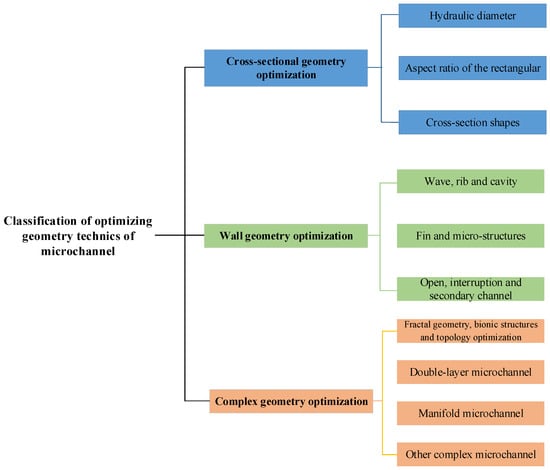
Figure 1.
Classification of optimizing geometry technology of microchannel.
2.2. The Mechanism of Optimizing Geometry Technology for Microchannel Heat Transfer
Appropriate geometric structure design can optimize the flow characteristics in the microchannel, thereby enhancing the heat transfer effect. The mechanism of the optimized geometry technology in the microchannel heat transfer can be roughly divided into the following categories, as shown in Figure 2. The main explanations are as follows:
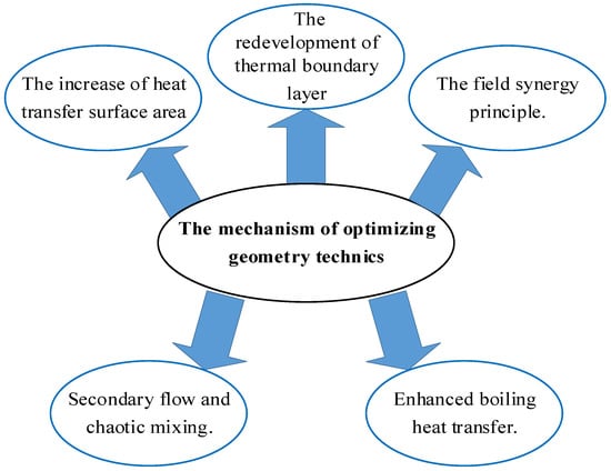
Figure 2.
The mechanism of optimizing geometry technology.
- The increase of heat transfer surface area. Optimizing the geometric structure can increase a larger surface area to volume ratio. The application of optimized geometric techniques, such as a smaller section size [26], complex section shapes [27], wall ribs [28,29,30], cavities [31], and pin fins [32] can effectively improve the heat transfer surface area.
- The redevelopment of the thermal boundary layer. The conventional straight channel fully develops the thermal boundary layer along with the flow direction. The hot fluid accumulates at the edge of the channel. The heat exchange between the mainstream cold fluid and the wall is limited. The optimized geometry technology interrupts and re-develops the developed thermal boundary layer through ribs [33], pin fins [34], and microstructures [35] to promote the mixing of hot and cold fluids.
- Secondary flow and chaotic mixing [36]. The optimized geometry technology generates secondary flow and fluid mixing locally in the microchannel. This accelerates the fluid flow, enhances the turbulence, reduces laminar stagnation zones, and increases the disturbance to the central mainstream cold fluid.
- Enhanced boiling heat transfer [37]. For the flow-boiling heat transfer, the optimized geometry technology is very important for the control and guidance of bubble behavior, increasing bubble nucleation, controlling the frequency of bubble detachment, and forming a suitable thin liquid film, which is beneficial to heat transfer augmentation.
- The field synergy principle [38]. The optimized geometry technology can improve the synergistic relationship between the fluid velocity field and the temperature gradient field to enhance the overall heat or mass transfer capacity.
3. Cross-Sectional Geometry Optimization
Due to the microchannel’s micro/small scale, the microchannel’s cross-sectional geometry has a significant influence on the microchannel heat sink. The cross-sectional geometric characteristics affect the area of heat transfer in the microchannel, the development of the thermal boundary layer, and the bubble behaviors, determining the microchannel heat sink’s flow and heat transfer characteristics. The influence of cross-sectional geometric characteristics on the microchannel heat sink is reviewed from the two aspects of size and shape.
3.1. Sizes of Cross-Sectional Geometry
The scale involved in most microchannel design dimensions is basically between 0.1 and 1.5 mm [39], which lies in the transition zone of macrophysics and microphysics. The physical processes in microchannels almost simultaneously have the characteristics of macrophysics and microphysics. Compared with single-phase flow, boiling and bubble behaviors under phase change heat transfer are more sensitive to the influence of channel size and surface tension [40]. The geometric cross section and size make the development and movement of bubbles have greater restrictions. The bubble volume changes drastically, which greatly affects the flow characteristic and heat transfer of microchannel flow boiling. In the review in this section, the influence of the microchannel size is mainly analyzed from the two perspectives of the hydraulic diameter of the microchannel and the aspect ratio of the rectangular cross section.
3.1.1. Hydraulic Diameter
Tuckerman et al. [9] studied the rectangular cross-section microchannel heat sink and estimated the convective heat transfer coefficient h according to the dimensionless formula, which can be expressed as Equation (1). For a given cooling fluid, it is believed that reducing the hydraulic diameter D of the microchannel has a significant effect on increasing the flow heat transfer coefficient. Therefore, the hydraulic diameter of the microchannel can be used as a consideration for enhancing heat transfer. The typical studies [26,41,42,43,44] on the hydraulic diameter of the microchannel as the enhancement of heat transfer have been summarized in Table 1.

Table 1.
Selected studies of hydraulic diameter on heat transfer.
The single-phase heat transfer in microchannels with the hydraulic diameter of 318~903 µm and the aspect ratio of about five was experimentally studied by Lee et al. [41]. The results showed that at a certain mass flux, the heat transfer coefficient increases with the decrease of the channel size. In microchannel single-phase flow heat transfer, the relationship between heat transfer and hydraulic diameter seems straightforward. For flow-boiling heat transfer, Markal et al. [26] experimentally studied the effects of hydraulic diameters of 100, 150, 200, and 250 μm on the flow-boiling pressure drop and heat transfer characteristics in parallel rectangular microchannels with a square cross section. Similarly, the hydraulic diameter has a significant effect on heat transfer characteristics. However, compared with single-phase flow, the influence of hydraulic diameter on heat transfer performance under flow boiling is not monotonous. However, according to the heat flux and mass flux, designers can select the appropriate hydraulic diameter to obtain the best heat transfer performance [42]. Sadaghiani et al. [43] conducted a study on the influence of pipe diameter on the boiling of subcooled flow in a horizontal circular pipe. Tests were performed on micro round tubes with inner diameters of 600 and 900 μm, respectively. Within this size range, the smaller the diameter of the microtube, the greater the heat transfer coefficient. In addition, the heat transfer of subcooled boiling is related to the diameter and flow conditions of the microtubes. In microtubes with a smaller diameter, the influence of mass flux is stronger than heat flux. Yang et al. [44] studied the heat transfer effect of flow boiling in multi-microchannel radiators with different hydraulic diameters (480 µm and 790 µm) through experiments. The experimental results showed that under the same mass flux and heat flux, the heat transfer coefficient of the 480 µm channel is generally higher than the bigger channel. Moreover, the flow patterns of the two channels are quite different. This corresponds to the difference in flow pattern between the two channels. However, when the flow reversal occurs, the heat transfer coefficient of the smaller channel drops significantly.
In this section, the effect of hydraulic diameter on single-phase and flow-boiling heat transfer in microchannels is reviewed. In single-phase flow, the effect of hydraulic diameter is relatively single, and heat transfer increases as it decreases. However, for microchannel flow boiling, the small channel has an obvious restriction on bubble behavior, and the bubbles may elongate, the liquid film may dry up, and the flow may become unstable, which causes greater flow resistance and deterioration of heat transfer [45]. Therefore, the design of the hydraulic diameter of the microchannel should be coordinated with other influencing factors, such as the mass flux of the working fluid and the heat flux, to achieve the best heat transfer performance. However, under the condition of ensuring the cross-sectional aspect ratio, there are few articles that study flow boiling under different hydraulic diameters. This will cause difficulties in the coordinated design of the hydraulic diameter and working conditions of the microchannel. Therefore, it is necessary to further explore the influence of hydraulic diameter on the two-phase flow pattern under the condition of ensuring the same cross-sectional geometry, so as to maintain the optimal two-phase flow pattern in the microchannel to enhance heat transfer.
3.1.2. Aspect Ratio
Rectangular cross-section channels have been studied for many years as a traditional microchannel design. Figure 3 shows all the microchannel geometries studied in published papers through the end of 2018 [24]. More than half of the research is on rectangular microchannels. Their rectangular aspect ratio (AR) structure has an important influence on the microchannel heat transfer. Especially in the flow boiling of the microchannel, the rectangular size is directly related to the bubble behavior, and the spreading of the liquid film affects the heat transfer. The distribution of the liquid film at different rectangular aspect ratios is shown in Figure 4 [46]. It can be clearly seen that, compared with the circular cross section, the liquid film distribution of the rectangular cross section is not uniform and is also different in different aspect ratios, which will affect the heat transfer process of the liquid film evaporation.
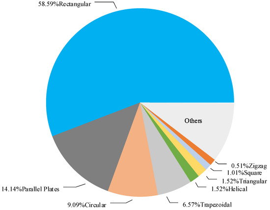
Figure 3.
The cross-sectional geometries of microchannels in the published papers (adapted from Ref. [24]).
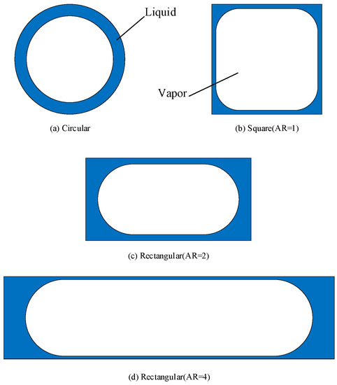
Figure 4.
The distribution of the liquid film in microchannels with different cross sections (adapted from Ref. [46]).
Naphon et al. [47] and Xie et al. [48] studied the single-phase flow of the microchannel heat exchanger and analyzed the effect of rectangular microchannel size on heat transfer. The typical studies [47,48,49,50,51,52,53,54,55,56] on aspect ratio and microchannel heat transfer are listed in Table 2.
Table 2.
Selected studies of aspect ratio on heat transfer.
Compared with single-phase flow, the influence of the rectangle aspect ratio under flow boiling is complicated. More scholars focus on the influence of microchannel size under flow boiling [49,50,51,52,53]. Lee and Mudawar [50] experimentally studied the cooling performance of four different microchannel sizes. They found that the bubble nucleation and aggregation in the microchannel with small hydraulic diameter are less. A smaller microchannel width may promote the growth of slender bubbles up to the channel width and is conducive to the flow stability and delays the occurrence of CHF. In the second part [51], the heat transfer characteristics of the two-phase microchannel were studied. Smaller hydraulic diameter microchannels can improve the cooling performance by increasing the flow velocity and wetting area, while the smaller width of the microchannels will cause the two-phase flow pattern to transition to slug flow in advance, which will reduce the cooling performance. Harirchian et al. [52] experimentally studied the flow-boiling heat transfer of FC-77 in the microchannel. The depth of the microchannels was 400 μm, and the width of the microchannels was between 100 and 5850 μm. The experimental results showed that the pressure drop grows as the channel width decreases. When the heat flux remains constant, the increase in the width of the microchannel will increase the heat transfer coefficient on the one hand and will also reduce the maximum heat dissipation capacity of the microchannel on the other hand. In another article [53], the effects of channel width and depth, aspect ratio, and cross-sectional area on the boiling heat transfer of microchannels were studied. The results showed that the cross-sectional area of the channel plays a decisive role in the boiling mechanism and heat transfer performance of the microchannel, and the reduction of the cross-sectional area of the microchannel will increase the heat transfer coefficient. When the wall heat flux is constant, the decrease of the cross-sectional area of the microchannel will increase the pressure drop.
In order to study the effect of the rectangle aspect ratio on flow boiling, under the condition that the hydraulic diameter of the microchannels is consistent, Burak Markal et al. [54] investigated the effects of different aspect ratios (AR = 0.37, 0.82, 1.22, 2.71, 3.54, and 5.00) in parallel rectangular microchannels on the boiling characteristics of saturated flow with deionized water. The experimental results showed that the heat transfer coefficient will grow as the rectangle aspect ratio increases until AR = 3.54, but the opposite is true when AR > 3.54. At the same time, the experiment concluded that no clear relationship between flow resistance and rectangle aspect ratio existed. Microchannels with the same hydraulic diameter (about 1.12 mm) and different rectangle aspect ratios of 0.83, 0.99, 1.65, 2.47, 4.23, and 6.06 were designed by Ben-Ran Fu et al. [55]. The results showed that the microchannel aspect ratio has a significant influence on flow-boiling heat transfer. The wall critical heat flux (CHF) grows as the rectangle aspect ratio increases and reaches a peak value at AR = 0.99. This is considered to be the effect of the liquid film in the corner.
In the literature review in this section, under the premise of ensuring a certain hydraulic diameter of the microchannel, the influence of the rectangular cross-section channel’s aspect ratio on the flow-boiling convective heat transfer and pressure drop is analyzed. In terms of heat transfer characteristics for single-phase flow in microchannels, narrow and deep channels have better heat transfer effects. For flow boiling, bubble behavior and liquid film spreading are the keys to heat transfer. Generally, as the channel width increases, the heat transfer effect will also be improved, but too large a width will make the diameter of the water increase unfavorably for heat transfer. The area of the cross section determines the heat transfer mechanism of flow boiling. The area decreases, and the heat transfer increases. The rectangle aspect ratio has an important effect on the two-phase boiling heat transfer. When the hydraulic diameter is constant, the rectangular microchannel with an aspect ratio of about one seems to have a better heat exchange effect than other aspect ratio microchannels [54,55,56]. In terms of pressure drop, due to the complex flow and boiling behavior of microchannels, many factors are affected, and the influence of the geometric factors of the rectangle aspect ratio on the microchannel pressure drop is not clear. Pressure drop as a critical factor of energy consumption deserves deeper and wider research.
3.2. Cross-Section Shapes
The cross-sectional shape of the microchannel has a significant effect on flow and heat transfer, just like the rectangle aspect ratio. With the advancement of processing technology, microchannels of various cross-sectional shapes have the possibility of being manufactured and applied. In recent years, many scholars have carried out research on microchannels with different cross-sectional shapes [57,58,59,60,61,62,63,64,65]. Rectangular, triangular, circular, and elliptical cross sections are often used in the comparative study of microchannel geometric cross sections, as shown in Figure 5.
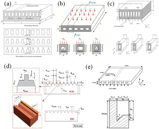
Figure 5.
Schematic diagram of various geometric cross-section microchannels: (a) Wang et al. (adapted from Ref. [57]); (b) Jing et al. (adapted from Ref. [58]), (c) Salimpour et al. (adapted from Ref. [59]), (d) Raj et al. (adapted from Ref. [64]), (e) Khan et al. (adapted from Ref. [65]).
Numerical studies were carried out on the influence of geometric parameters on the flow and heat transfer characteristics of rectangular, trapezoidal, and triangular microchannel heat sinks [57], as shown in Figure 5a. A rectangular microchannel’s aspect ratio is 8.904–11.442, which has the best performance. The hydraulic and thermal properties of water in rectangular, elliptical, and isosceles triangular microchannels are numerically studied by solving 3-D steady-state and conjugate heat transfer models [58]. The geometric picture of the microchannel cross section is shown in Figure 5b. It is found that the hydraulic resistance and convective heat transfer coefficient of the triangular microchannel are the smallest. When the hydraulic diameter of the cross-section channel is smaller than the critical diameter, the hydraulic resistance of the rectangular microchannel is larger, and the convective heat transfer coefficient is larger. Conversely, elliptical microchannels are better. Numerical models of microchannel heat sinks with rectangular, elliptical, and isosceles triangle cross-sectional shapes were established by Salimpour et al. [59], as shown in Figure 5c. The simulation results showed that the thermal performance of rectangular and elliptical microchannel heat sinks is very similar, and the thermal performance of isosceles triangular microchannels is the worst.
Similarly, other researchers have conducted many studies. Luo et al. [60] used numerical simulation methods to study the flow-boiling heat transfer characteristics in vertical microchannels with circular, square, triangular, and trapezoidal cross sections. With the increase of mass flux, the average heat transfer coefficients of the four channels all increase. The circular and square microchannels can increase the heat transfer coefficient by 30%, but it is still lower than the triangular channel’s heat transfer coefficient because with the growth of mass flux, the inertial force of incoming flow increases, the surface tension of small bubbles near the wall is less than the inertial force, and they are washed downstream by the incoming flow before they grow. The rapid separation of bubbles increases the disturbance to the mainstream fluid, and the average heat transfer coefficient increases. At the same time, the triangle corner region will limit the radial growth of bubbles, adhere to the wall, and accelerate the bubble fusion and fragmentation. The evaporation speed of the thin liquid layer between the bubble and the wall is accelerated, and the heat transfer is enhanced. Sempértegui-Tapia et al. [61] found that when the heat flux is low, the heat transfer performance of the circular channel is the best, and when the heat flux is high, the heat transfer performance of the triangular channel is the best. When the geometry remains unchanged, as the heat flux increases, the heat transfer coefficient also increases. Goodarzi et al. [62] conducted numerical studies on microchannels with the same hydraulic diameter, channel length, and circular, rectangular, and trapezoidal cross sections. Under similar working conditions, the heat transfer effect of the rectangular cross-section microchannel is the best, but its pump power is also the most compared to others. The heat transfer efficiency in three types of microchannels with triangular, rectangular, and trapezoidal cross sections were compared by Chen et al. [63]. Unlike Goodarzi et al., Chen et al. [63] found that rectangular microchannels have the lowest thermal efficiency, and triangular microchannels have better thermal efficiency than trapezoidal microchannels.
The composite structure of several geometric cross sections are also studied. Raj et al. [64] designed a novel stepped convergence microchannel structure, as shown in Figure 5d. The stepped convergence microchannel is a combination of a V-shaped channel at the bottom and a stepped channel with a wider convergence at the top. Compared with the rectangular cross-section microchannel, the heat transfer coefficient of the stepped convergent microchannel is increased by 98%, and the total pressure drop is reduced by 77%. It also reduces the fluctuation of wall temperature and pressure drop and reduces the instability of flow boiling. Geometric optimization of complex sections is important. Khan et al. [65] used the 3-D Navier–Stokes analysis and optimized the algorithm to optimize the inverted trapezoidal cross-section microchannel heat sink. Optimized from the three aspects of microchannel width, depth and angle, as shown in Figure 5e, it was found that the thermal resistance and the pressure drop are most sensitive to design of the microchannel width. As the width and angle of a microchannel increase, the thermal resistance grows linearly, while the pressure drop reduces. However, with the channel depth, the trend is the opposite.
In this part of the review, we examine the geometric cross-section shapes of the microchannel mainly designed to enhance the heat transfer by increasing the heat transfer area and spreading the liquid film in the two-phase flow. However, different cross-sectional shapes’ hydraulic and heat transfer characteristics have different performance results, and it is not easy to draw conclusions. The main reason is that articles can be roughly divided into two categories. One is to study channels with different cross-sectional shapes, such as rectangles, trapezoids, and circles. The size of such different cross-sectional shapes is generally fixed, and it is difficult to compare the advantages and disadvantages of different cross-sectional shapes. Another type of article is the study of the size optimization of a certain cross-sectional shape. There is still a lack of systematic comparative studies on microchannels’ hydraulic and thermal properties for different shapes after size optimization.
4. Wall Geometry Optimization
In this section, only the geometric design and optimization of the microchannel wall are discussed. It is mainly divided into three parts. First, the geometric modification of the two side walls inside the microchannel, such as the common wave design, the ribs protruding from the sidewalls, and the cavity protruding out of the channel, are examined. Second, the geometric modification of the bottom surface of the microchannel, such as pin fins, interruptions, and the design and arrangement of microstructures are discussed. Finally, the geometric modification of the channel wall, such as the adjustment of the wall height-open microchannel, the interruption of the straight channel, and the multiple interruptions of the wall, called the secondary channel, is detailed. The typical studies on geometric optimization on the sidewall and bottom wall of the microchannel as heat transfer augmentation are summarized in Table 3.
4.1. Wave, Rib, and Cavity on Sidewall
Owing to the limitation of the size of the microchannels, the straight microchannels are basically laminar flow, the streamlines are almost straight, the fluid mixing effect is poor, and the thermal performance is lower than that of the turbulent flow. With the development of the thermal boundary layer, the heat transfer effect worsens along the fluid flow direction. Many studies have focused on the design of the microchannel geometry on the sidewall to increase fluid disturbance to achieve the effect of microchannel heat transfer, such as the design of wave-shaped microchannels and adding ribs and cavities on the sidewall, as shown in Figure 6.
This paragraph mainly reviews the wavy microchannel. Lin et al. [33] improved the design of wave-shaped microchannels using a numerical model, as shown in Figure 6a, comparing the heat transfer performance of straight channels and different wave-shaped microchannels. It was found that reducing the wavelength or increasing the amplitude is beneficial to the formation of eddy currents, which is conducive to improving heat transfer performance. Appropriate wavelength and amplitude can further improve heat transfer performance. Mohammed et al. [66] conducted further research on the waveform microchannel. It was found that as the amplitude of the wave-shaped microchannel rises, the pressure drops and friction coefficient of the wave-shaped microchannel increase proportionally, and it is always higher than that of the straight microchannel. In general, the amplitude of the wave-shaped microchannels in the range of 0.0625 to 0.21875 has better cooling performance. Similarly, Tiwari et al. also performed parameter optimization of wavy microchannels [67] and conducted a simulation study to explain the effect of bubble coalescence on two-phase flow-boiling heat transfer and instability [68,69]. Sui et al. [70] found that the vortex generated by the wave shape of the wall can greatly promote the mixing of the boundary fluids and the center fluids, and the pressure drop loss of the wave-shaped microchannel did not increase much. The wave amplitude of the wall can be changed according to the actual purpose, resulting in higher heat transfer performance and more uniform wall temperature. In order to alleviate the problem of local hot spots, local wave-shaped microchannels were designed in the higher part of the high heat flux area. Xu et al. [71] designed a new geometric microchannel heat sink with dimples based on wave microchannels. The simulation results showed that the wave-shaped channel can enhance the thermal performance of the new model by increasing the velocity gradient near the throat wall and the method of strong cross-flow mixing. The dimples enhance heat convection by destroying the boundary layer.
Geometric modification and optimization of ribs are often applied to sidewalls. Chai et al. [28] designed five different shapes of microchannel heat sinks with offset ribs, including rectangle, back triangle, isosceles triangle, front triangle, and semicircle, as shown in Figure 6b. The solved numerical model results showed that several kinds of offset ribs have similar heat transfer enhancement effects and are significantly better than straight channels without offset ribs. In addition, due to the significant increase in pressure drop, the new microchannel is not suitable for working conditions at high Reynolds numbers. A series of studies [28,29,30,72,73,74] were carried out on ribs. The effect of the arrangement of the triangular ribs on the local flow of the microchannel was comparatively studied [29,30], as shown in Figure 6c. Similar results to the above article, higher pressure drop, and lower thermal resistance, are brought about by the triangular ribs. Compared with the reference straight microchannel, the optimized new microchannel can increase the average Nusselt number up to 2.15 times. Compared with the microchannels with offset triangular ribs and the microchannels with the same rib shape and aligned with the triangular ribs, the heat exchange performance is similar, but the pressure drop is much lower. The influence of different geometrical parameters, fan-shaped rib width, height and spacing, arrangement, or offset arrangement on the microchannel heat sink, is analyzed [72,73,74]. Compared with the traditional smooth microchannel, fan-shaped ribs can bring better overall performance. The geometric parameters of fan-shaped ribs have been optimized, and a suitable range of geometric parameters of microchannel heat sinks is recommended.
Table 3.
Selected studies of geometric optimization on sidewall and bottom wall of the microchannel on heat transfer.
Table 3.
Selected studies of geometric optimization on sidewall and bottom wall of the microchannel on heat transfer.
| Reference | Type of Wall Geometry Optimizations | Research Method/ Fluid/ Flow Pattern | Heat Transfer/ Flow Resistance/ Mechanism |
|---|---|---|---|
| Lin et al. [33] | Wave on sidewall | Simulation/ Water/ Single-phase flow | ΔT , Nu , Nu /-/ /-/Enhanced chaotic mixing and convection, and increased heat transfer surface area |
| Mohammed et al. [66] | Wave on sidewall | Simulation/ Water/ Single-phase flow | h /ΔP/ /ΔP/Enhanced chaotic mixing and convection, and increased heat transfer surface area |
| Xu et al. [71] | Cavity on bottom wall | Simulation/ Water/ Single-phase flow | Nu15%/ΔP2%/ Enhanced chaotic mixing and convection, and increased heat transfer surface area |
| Chai et al. [28] | Rib on sidewall | Simulation/ Water/ Single-phase flow | Nu42~95%/ΔP/ Enhanced chaotic mixing and convection, and increased heat transfer surface area |
| Kumar et al. [31] | Cavity on top wall and bottom wall | Simulation and experiment/Water/Single-phase flow | Nu/ΔP/Enhanced convection, and increased heat transfer surface area |
| Chai et al. [75] | Cavity on sidewall | Simulation/ Water/ Single-phase flow | Nu/ΔP/ Enhanced convection, redeveloped boundary layer, and increased heat transfer surface area |
| Li et al. [76] | Cavity on sidewall | Experiment/ Acetone/ Flow boiling | h155~988%/ ΔP 12.8~50.3%/Enhanced convection, and increased heat transfer surface area |
| Chai et al. [77] | Cavity on sidewall | Simulation and experiment/ Water/ Single-phase flow | h12.5~80.4%, Nu 180%/ΔP/Enhanced convection, and increased heat transfer surface area |
| Xia et al. [78] | Rib and cavity on sidewall | Simulation/ Water/ Single-phase flow | Nu167%/- /Enhanced chaotic mixing and convection, and increased heat transfer surface area |
| Deng et al. [79] | Fin on bottom wall | Experiment/ Water and ethanol/ Flow boiling | h10~175%/- /Enhanced chaotic mixing and convection, and redeveloped boundary layer |
| Xie et al. [35] | Micro- structures on bottom wall | Simulation/ Water/ Single-phase flow | h40~80%, R41.02%/ ΔP /Enhanced convection, redeveloped boundary layer, and increased heat transfer surface area |
| Rajalingam et al. [80] | Micro- structures on bottom wall | Simulation/ Water/ Single-phase flow | h161~170%/ΔP /Enhanced chaotic mixing and convection, and redeveloped boundary layer |
| Ahmadian-Elmi et al. [81] | Fin on bottom wall | Simulation/ Air/ Single-phase flow | h/ΔP /Enhanced chaotic mixing and convection, and redeveloped boundary layer |
| Zeng et al. [82] | Fin on bottom wall | Simulation and experiment/ Water/ Single-phase flow | Nu56~260%/ ΔP 9~27%/Enhanced chaotic mixing and convection, and redeveloped boundary layer |
The geometry of the cavity is another common geometric modification of the channel sidewall. Kumar [31] established a three-dimensional microchannel model with a trapezoidal cross section with rectangular and semicircular cavities on the wall, as shown in Figure 6d. After a systematic comparison, it was found that the heat transfer performance of the microchannel with the semicircular groove was 16% better than that of the rectangle. The pressure drop increased due to friction losses. At the same time, the influence of the number and size of grooves on heat transfer was also studied. After the groove reaches a certain number, the heat transfer performance is no longer enhanced, and the pressure loss continues to increase. For rectangular cavities of the same area, the width has a greater influence on the heat transfer augmentation. The periodic fan-shaped cavity microchannel heat sink was also studied [75]. The results showed that the microchannel heat sink with fan-shaped cavities on the sidewalls is beneficial to heat transfer enhancement under an acceptable pressure drop. The mechanism of heat transfer augmentation can be attributed to the increase of the heat transfer surface area, the formation of the boundary layer, and the throttling effect. Therefore, the size, style, and arrangement of the cavity are important parameters for geometric optimization. Li et al. [76] designed a new microchannel with triangular cavities on the wall and conducted a comparative study of flow-boiling experiments between the new microchannel and the straight microchannel. The new microchannel heat sink’s heat transfer, pressure drop, and wall temperature performance were analyzed. The results showed that the new microchannel has an inhibitory effect on bubble accumulation in flow boiling, can improve CHF compared with straight microchannels, and enhances the stability of flow boiling. At the same time, the local heat transfer coefficient can even reach 8.55 times the local heat transfer coefficient of the traditional straight microchannel at the steady flow-boiling process, and the pressure drop is also significantly lower. However, boiling and flow reversal are more severe under low mass flux, and the result is not optimistic. Chai et al. [77] studied the heat transfer efficiency of microchannel heat sinks with periodic cavities through experiments and numerical methods. The thermal and hydraulic characteristics of three different microchannels (straight, semicircular cavity, and triangular cavity) were compared. The geometric structure diagram is shown in Figure 6e. The conclusion is that the pressure drop of different types of microchannels is similar, but when the Reynolds number is greater than 300, the pressure drop of the periodic cavity microchannel exceeds that of the traditional straight microchannel. At the same time, the average Nusselt number of the periodic cavity microchannel can be increased by about 1.8 times, the heat transfer fluctuation of the new microchannel is reduced, and the wall temperature is more uniform.

Figure 6.
Schematic diagram of various geometry on the sidewall of microchannels: (a) Lin et al. [33], (b) Chai et al. (adapted from Ref. [28]), (c) Chai et al. (adapted from Refs. [29,30]), (d) Kumar [31], (e) Chai et al. (adapted from Ref. [77]), (f) Zhai et al. (adapted from Ref. [38]).
Combining the advantages of cavities and ribs and optimizing geometry on the sidewall can further improve heat transfer. Xia et al. [83] optimized the geometric dimensions of the microchannel and combined the arc-shaped grooves and ribs with an algorithm. Taking the total thermal resistance and pump power as the optimization goals and taking the groove height, rib height, and rib width as variables, the numerical results were compared and studied. The thermal resistance drops linearly as the relative rib height increases. Both the total thermal resistance and the pump work increase with the relative rib width. The sensitivity analysis showed that the relative height of the rib plays the greatest role on the microchannel. They also numerically studied [84] the influence of geometric parameters on the hydraulic and thermal characteristics of a microchannel heat sink with a triangular cavity. Four variables were designed to represent the distance and geometric shape of the triangular cavity. It also gave the best parameter range that helps to design an efficient microchannel heat sink. Beng et al. [85] proved that the triangular cavity microchannels have the highest Nusselt number and the lowest friction factor compared with the straight channels. When the fluid flows through the triangular cavity, it will disturb the fluid and form a vortex. Therefore, the size and strength of the cavity affect the strength of forced convection. In addition, Xia et al. [78] studied a combined microchannel heat sink with a fan-shaped cavity and internal ribs with the numerical method. The results showed that the combined effect of the cavity and the rib optimizes the cavity alone action, and the influence of rib height is the biggest influencing factor of geometric optimization compared to cavity. Similar microchannel heat sink with fan cavities and different ribs were studied by Zhai et al. [38], as shown in Figure 6f. The field synergy theory, the reconstruction of the boundary layer, and the disturbance of the fluid were used to explain the mechanism of heat transfer augmentation. Tiwari et al. [86] explained the heat transfer principle of sidewall geometry modification from the perspective of velocity and pressure distribution, as shown in Figure 7. The change of flow cross section caused the change of fluid velocity, flow interruption, boundary layer redevelopment, and secondary flow, which are the main reasons for heat transfer augmentation. In addition, it was found that the heat entropy of the wall geometry modification region was higher, indicating that the heat transfer was more sufficient [87].
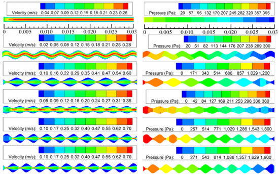
Figure 7.
Comparison of velocity and pressure distribution of various geometry on the sidewall of microchannels (adapted from Ref. [86]).
Compared with straight channels, microchannels with ribs and cavities have a larger heat transfer surface area and can enhance chaotic mixing and convection, increase disturbance, and promote the reconstruction of the boundary layer to enhance heat transfer. However, it can be seen from Table 3 that these geometric modifications have increased the channel pressure drop to a certain extent. This will increase pump power consumption and the risk of leakage, contrary to the concept of sustainable development of energy conservation. Various geometric structures, such as wave-shaped composite structures coupled with cavities and ribs, can realize enhanced heat transfer while reducing the increase in pressure drop caused by wall geometry modification after geometry optimization.
4.2. Fin and Microstructures on Bottom Wall
Similar to the previous section, in order to strengthen the disturbance of the internal fluid of the microchannel and promote the reconstruction of the boundary layer, some of the microstructure design of the bottom surface of the microchannel was introduced. Shamsi et al. [34] used a numerical simulation method and analyzed the flow and heat transfer process of rectangular cross-section microchannels with triangular ribs with different angles (30°, 45°, and 60°), as shown in Figure 8a. At an angle of attack of 30°, the growth of the thermal boundary layer before and after the ribs was significantly smaller, which proved that the larger heat transfer at this angle is reasonable. Deng et al. [79] added a micropin fin structure on the bottom surface of the microchannel. The experiments showed that the heat transfer effect of the new microchannel has obvious advantages compared with the traditional microchannel with smooth walls. A large number of tiny retrograde cavities provided many stable nucleation sites. In addition, the capillary force they can provide is conducive to the rewetting of the wall surface, which relieves local dryness to a certain extent, and the instability of the two-phase flow is reduced. Therefore, the high heat transfer coefficient can be maintained under high heat flux. Foong et al. [88] designed a square microchannel with four longitudinal-shaped fins by numerical method, and the height of the fins was optimized. It was found that the internal fins had the possibility of enhancing heat transfer, and there is an optimal height of fin, which can provide the best thermal and hydraulic characteristics. The internal fins enhanced the development of the boundary layer, strengthened flow mixing, and increased the heat transfer surface area and thus improved the heat transfer coefficient. Xie et al. [35] designed a Y-shaped bifurcation in the straight microchannel, as shown in Figure 8b, and studied the influence of the length and angle of the Y-shaped bifurcation. Under certain conditions, the thermal resistance was reduced by about 40%. When the angle of Y-shaped bifurcation is 180°, that means T-shaped, it has the best thermal performance. However, at the same time, a large angle also brings a higher pressure drop. Rajalingam et al. [80] discussed the effect of the shape and distribution of pin fins and holes on the thermal–hydraulic performance of a microchannel with the simulation method. The distribution and shape of circular, elliptical, and aerofoil fins and circular and oval blind holes were analyzed. Compared with rectangular straight channels, the highest thermal–hydraulic performance of elliptical fins can be improved by 19.4%.
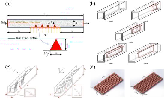
Figure 8.
Schematic diagram of pin fins and microstructures microchannels: (a) Shamsi et al. (adapted from Ref. [34]), (b) Xie et al. (adapted from Ref. [35]), (c) Xie et al. (adapted from Ref. [32]), (d) Zeng et al. (adapted from Ref. [82]).
Compared with the geometric modification of the microstructure on the wall, the optimization of geometric structure is also noteworthy. Ahmadian-Elmi et al. [81] optimized the number, diameter, spacing, height, and other geometric parameters of pin fins to improve the overall performance of the pin-fin microchannel heat sink. The optimized tapered pin fins can improve thermal–hydraulic performance by 17.58% compared with ordinary pin fins. The arrangement and the inclined angle of cylindrical pin fins were also studied by Xie et al. [32], as shown in Figure 8c. It showed that the arrangement and the inclined angle of pin fins have almost no effect on heat transfer. Zeng et al. [82] designed a new type of microchannel heat sink with complex structure pin fins, as shown in Figure 8d. Staggered complex pin fins have better thermal performance and also have larger pressure drop. Compared with conventional rectangular microchannel heat sink, its Nusselt number increased by 77–260%.
In fact, similar to the geometric modification and optimization on the sidewall, the microstructures and fins on the bottom wall increase fluid mixing by destroying the original stable flow, forming secondary flow, and redeveloping the thermal boundary layer to promote heat transfer. Unlike the former, the fins and microstructures on the bottom wall have more potential applications in two-phase flow to increase nucleation sites to enhance flow-boiling heat transfer. However, they all increase the pressure drop to some extent. Hence, how to obtain balance between the enhancing heat transfer and reducing pressure drop is the main problem that should be solved in the future.
4.3. Open, Interruption, and Secondary Channels
The geometric modification of the wall of the microchannels, such as waves, fins, cavities, pin fins, microstructures, etc., all increase heat transfer and at the same time produce a greater or lesser pressure drop. Especially in the process of flow boiling, the restriction of the bubble behavior by the microchannel geometry will cause the pressure drop to rise sharply.
The open channel provides a wider space for the bubbles generated by boiling, decreasing the pressure drop and improving the critical heat flux. Xia et al. [89] experimentally compared the flow-boiling characteristics of acetone in a semi-open microchannel and a straight microchannel, as shown in Figure 9a. Compared with straight microchannels, the initial boiling point of semi-open microchannels is lower because it can provide a greater number of nucleation sites. Under the same experimental conditions, the maximum heat transfer coefficient of the semi-open channel is 1.4 times the conventional microchannel. Yin et al. [90] proposed an open microchannel heat sink and discovered two types of stratified flow with an opposite distribution of vapor and liquid phases. Nucleate boiling is the main boiling mechanism, the behavior of bubbles is guided by the structure, and the instability of flow boiling is obviously suppressed. In subsequent studies, two sizes of open microchannel heat sinks were used as a comparative study [91], as shown in Figure 9c. Similarly, two types of stratified flow were discovered. However, both nucleate boiling and convective evaporation dominate the mass transfer process of flow boiling. More parallel channels and the smaller size of the open microchannel heat sink is better for heat transfer, but the pressure drop is greater. Balasubramanian et al. [92] studied the effects of different spatial orientations on flow boiling in open microchannels. The experimental results showed that the influence of the change of inertia and the direction of gravity on the flow-boiling heat transfer of open microchannels can be ignored. Bhandari et al. [93] conducted a numerical study on an open microchannel heat sink composed of square pin fins, as shown in Figure 9b, and compared the results with closed microchannels. The open microchannel with a fin height of 1.5 mm had the best comprehensive hydraulic and thermal performance, and its heat transfer rate was 5–10% higher than that of a closed microchannel heat sink (the fin height is about 2 mm).
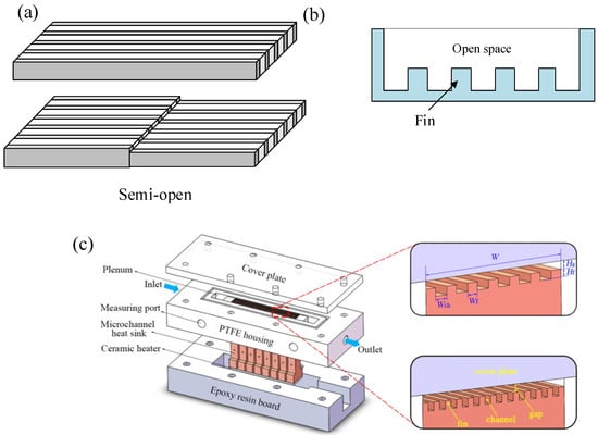
Figure 9.
Schematic diagram of open microchannels: (a) Xia et al. ([89]), (b) Bhandari et al. ([93]), (c) Yin et al. (adapted from Ref. [91]).
In order to enhance the heat exchange of the microchannels while reducing the increase in pump power, the geometric design of the secondary flow channel is proposed to be applied to the heat exchanger. It retains the enhanced heat transfer effect of the fins and cavities and improves the flow between the channels, so as to achieve the effect of controlling the pressure drop. The new structure’s design also means more adjustments and optimizations of geometric parameters, such as channel interruption distance, interruption angle, etc.
The application of interrupted microchannels in single-phase flow is to increase disturbance by mutual flow between channels to enhance heat transfer and reduce pressure drop. Xu et al. [94] designed an interrupted microchannel heat sink, as shown in Figure 10a, which includes adjacent discontinuous parallel microchannels and separation areas. The results showed that the flow rate difference of different channels is very small, and the deviation of the absorbed heat is less than 2%. The hydraulic and thermal boundary layer will disrupt and re-develop the interrupted microchannels, and the re-development of the thermal boundary layer will enhance the heat transfer of the heat exchanger. Compared to straight microchannels, the pressure drop of interrupted microchannels is always no greater than straight microchannels. Chai et al. [95] explored an interrupted microchannel heat sink with different geometry and layout parameters to study their pressure drop and heat transfer characteristics, as shown in Figure 10b. Interrupted microchannels with ribs can observe the separation of mainstream flow, recirculation, or vortex and interrupt the boundary layer. When the Reynolds number is small, the heat transfer can be enhanced. When the width of the rectangular fin is 0.5 mm, the heat transfer coefficient is better. When the Reynolds number is large, the heat transfer effect of the interrupted microchannel without fins is the best. Once the Reynolds number is less than 500, microchannels with fin spacing greater than 1.3 mm provide the highest heat transfer enhancement factor, and then as the Reynolds number increases, the optimal channel spacing gradually increases.
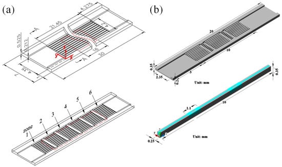
Figure 10.
Schematic diagram of interrupted microchannel: (a) Xu et al. (adapted from Ref. [94]), (b) Chai et al. (adapted from Ref. [95]).
More studies on secondary channel microchannels formed by the increased number of interruptions are reviewed in this paragraph, and the typical studies on open, interruption, and secondary channel microchannels as heat transfer augmentation are summarized in Table 4. Prajapati et al. [96] compared the bubble growth and flow instability of uniform, divergent, and secondary channel microchannels through experiments, using visualization techniques to analyze and compare the aggregation and movement of bubbles in the three channels and found, as shown in Figure 11a, that the bubble growth model is completely different from the uniform and divergent cross-sectional channel. Its bubble growth rate is small, and it has enough freedom to grow in the axial and lateral directions. It has an inhibitory effect on flow reversal and boiling instability. The temperature fluctuation and pressure loss of the bottom surface of the segmented channel are slightly higher. Experiments by Law et al. [37] compared the hydraulic and thermal performance and instability characteristics of straight fin microchannels and secondary channel microchannels, as shown in Figure 11b. The results showed that the heat transfer performance of secondary channel microchannels is significantly better than that of traditional straight microchannels, even up to 6.2 times, because the density of production bubbles in nucleate boiling increases and the destruction and regeneration of thin liquid films in convective boiling are beneficial to two-phase flow-boiling heat transfer. The inclined fins can stably chop up the bubbles so that the bubbles are limited to a certain size, thus providing a more stable flow boiling, and the CHF is greatly increased. However, the frequent changes in the fluid flow direction will bring higher pressure drops and pressure fluctuations. Shi et al. [36] optimized the geometric parameters in the trapezoidal fin secondary channel microchannel heat sink to obtain smaller thermal resistance and pump power, as shown in Figure 11c. Numerical research is carried out from three aspects of channel width, spacing, and angle. The results showed that the fin width has the greatest influence on the pump power and thermal resistance. As the fin width increases, more fluid flows into the secondary channel. Although the pump power decreases, the thermal resistance increases. Affected by the rupture and reconstruction of the heat transfer area and the boundary layer, the effect of the fin pitch on the thermal resistance is not monotonous. Five best solutions were determined through K-means clustering analysis. Compared with the traditional straight channel, the thermal resistance can be reduced by up to 29.2%, and the pump power can be reduced by up to 26.4%. Ghani et al. [97] designed straight channels, secondary channels, and fins and their combined microchannels and compared and analyzed different microchannels, as shown in Figure 11d. The results showed that the microchannels with secondary channels and fins have superior overall performance. The secondary channel provides a larger flow area, reduces the pressure drop caused by the fins, and helps to remove stagnant areas, enhancing disturbances and significantly improving heat transfer.
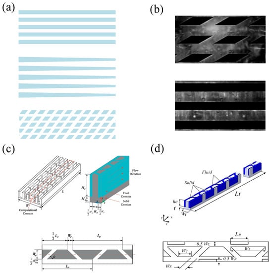
Figure 11.
Schematic diagram of secondary channel microchannel: (a) Prajapati et al. ([96]), (b) Law et al. (adapted from Ref. [37]), (c) Shi et al. (adapted from Ref. [36]), (d) Ghani et al. (adapted from Ref. [97]).
The optimization of the secondary channel microchannel is necessary. The following shows the optimization of the secondary channel from the shape, angle, and arrangement of the wall surface [90,91,92]. Wan et al. [98] designed and manufactured four fins with different shapes, namely square, round, diamond, and streamlined as the wall of the secondary channel, as shown in Figure 12a. A flow-boiling experiment of water was carried out. The square fins secondary channel presented the best heat transfer coefficient because the square shape facilitates hindering the continuous development of the steam block and causing the channel to re-wet. Diamond fins secondary channel exhibited the smallest pressure drop. The experimental results showed that the square fins secondary channel is most suitable for the secondary channel heat sink in the flow-boiling process. Law et al. [99] experimentally studied the effects of different tilt angles (10°, 30°, 50°) on thermal–hydraulic characteristics and stability of secondary channel microchannel flow boiling, as shown in Figure 12b. The results showed that the microchannel with an inclined angle of 50° has the largest heat transfer coefficient due to the larger number of inclined fins, which results in a greater degree of reformation of the boundary layer and liquid film. The pressure drop of the secondary channel with an inclination angle of 10° is the smallest, and the pressure drop of the secondary channel with an inclination angle of 30° and 50° is larger and close in size. Compared with straight channels, the flow and boiling stability of the secondary channel at any oblique angle is greatly improved. Huang et al. [100] designed three fins of secondary channel microchannel heat sinks, which are rectangular parallel fins, rectangular staggered fins, and trapezoidal staggered fins, as shown in Figure 12c. Numerical calculation results showed that increasing the width of the rectangular fin and the angle of the trapezoidal base augments heat transfer. The trapezoidal staggered fins secondary channel has the lowest pump power and the best heat transfer characteristics, and it is pointed out that the staggered fins secondary channel has a better degree of field synergy.
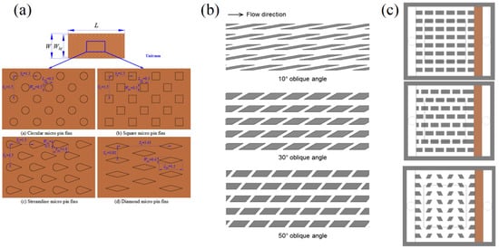
Figure 12.
Geometry optimization of the secondary channel: (a) Wan et al. (adapted from Ref. [98]), (b) Law et al. (adapted from Ref. [99]), (c) Huang et al. (adapted from Ref. [100]).
Table 4.
Selected studies of geometric optimization on open, interruption, and secondary channel on heat transfer.
Table 4.
Selected studies of geometric optimization on open, interruption, and secondary channel on heat transfer.
| Reference | Type of Wall Geometry Optimizations | Research Method/ Flow Pattern | Heat Transfer/ Pressure/ Mechanism |
|---|---|---|---|
| Xia et al. [89] | Open channels | Experiment/ Acetone/ Flow boiling | h36.2%/-/ Increased the number of nucleate sites to enhance flow boiling |
| Yin et al. [90] | Open channels | Experiment/ Water/ Flow boiling | h/-/ Increasing area for expanding bubble and increased the number of nucleate sites to enhance flow boiling |
| Balasubramanian et al. [92] | Open channels | Experiment/ Water/ Flow boiling | CHF, h/ΔP/ Increasing area for expanding bubble to enhance flow boiling |
| Bhandari et al. [93] | Open channels | Simulation/ Water/ Single-phase flow | Nu/ΔP/ Increasing area for expanding bubble to enhance flow boiling |
| Xu et al. [94] | Interruption channels | Simulation and experiment/ Water/ Single-phase flow | Nu/ΔP/ Enhanced chaotic mixing and convection, and redeveloped boundary layer |
| Chai et al. [95] | Interruption channels | Simulation and experiment/ Water/ Single-phase flow | Nu18~60%/-/ Enhanced chaotic mixing, and redeveloped boundary layer |
| Prajapati et al. [96] | Secondary channels | Experiment/water/ Flow boiling | -/ΔP/ Secondary flow and enhanced flow boiling |
| Law et al. [37] | Secondary channels | Experiment/ FC-72/ Flow boiling | h120~620%, CHF250~280%/ΔP/ Secondary flow and enhanced flow boiling |
| Shi et al. [36] | Secondary channels | Simulation/ Water/ Single-phase flow | R29.2%/ΔP26.4%/ Enhanced chaotic mixing, secondary flow, and redeveloped boundary layer |
| Ghani et al. [97] | Secondary channels | Simulation/ Water/ Single-phase flow | Nu/ΔP50%/ Enhanced chaotic mixing, secondary flow, and redeveloped boundary layer |
| Law et al. [99] | Secondary channels | Simulation and experiment/FC-72/ Flow boiling | h/ΔP/ Enhanced chaotic mixing, secondary flow, and redeveloped boundary layer |
Interrupting the microchannel creates conditions for the redevelopment of the boundary layer. Multiple local flow of heat development enhances heat transfer in the microchannel heat sinks and generally at pressure drops not higher than straight channels. The secondary flow channel gives full play to the advantages of the intermittent microchannels and fins and can significantly improve the heat transfer performance. The mechanism of heat transfer augmentation can be attributed to the larger heat transfer surface area, the periodic fragmentation of the boundary layer, and the fluid mixing caused by the growth of the secondary flow vortex. In addition, the geometric structure of the open microchannels suppresses flow-boiling instability because of the increasing area for expanding bubbles. The geometric optimization of the distribution, shape, size, and angle of the fins in the secondary channel is conducive to improving the critical performance of the microchannel heat sink. Cooperating with these geometric characteristics to reduce thermal resistance and pressure drop is a future research direction. Similarly, the influence of geometrical characteristics, such as the geometrical cross-sectional size and hydraulic diameter of the channel on the secondary flow channel, is also worth exploring.
5. Complex Geometry Optimization
The optimized design of the microchannel flow channel geometry is of great significance to enhance the overall heat transfer of the microchannel heat sink. The traditional multi-parallel microchannel geometric design urgently needs improvement in the face of the increasing demand for high heat flux dissipation. In this section, the flow channel geometry design and optimization of the microchannel heat exchanger are discussed. It is also mainly divided into three parts. First, the geometric design and topology optimization of flow channels in a microchannel heat sink based on fractal theory and bionics thinking are reviewed. Second, the geometric design and optimization of double-layer microchannels are used to reduce pressure drop and solve local hot spots. Finally, the geometric design and optimization of the manifold microchannels that have broad prospects in the application are introduced.
5.1. Fractal Geometry, Bionic Structures, and Topology Optimization
While microchannels bring higher heat dissipation efficiency, huge pressure loss has become a problem that cannot be ignored. Solving this problem has become a key issue in whether the microchannel heat sink can be applied. With the development of science and technology today, people’s research on fractal theory has gradually penetrated engineering. The fractal theory is a natural selection that began in nature. Tree roots, tree crowns, continuous mountains, human blood vessel networks, and river networks are all natural. The long-term evolutionary structures have the best or near-optimal structures in terms of heat transfer and mass transfer. Therefore, the use of fractal theory and bionics thinking to design microchannel structures has become the research direction of many scholars, and the typical studies on geometric optimization on fractal geometry as heat transfer augmentation are summarized in Table 5.
Tree elements are widely present in nature, such as the branches of trees, the veins of leaves, mountains and rivers, and so on. After a long period of evolution, its structure is close to the optimal structure. The microchannel has been improved to achieve a better heat exchange effect and smaller pressure drop. Guo et al. [101] experimentally studied the two-phase flow pattern and mass transfer process of tree-shaped parallel microchannels composed of T-shaped branches structure, as shown in Figure 13a. Four flow patterns of bubble flow, foam flow, slug flow, and compact slug flow in the branch structure were observed in the experiment. They found that the ratio of the liquid phase to the gas phase affects the uniformity of the flow distribution in the branch. Properly increasing the proportion of the gas phase before reaching the critical point can improve flow distribution uniformity. The influence of the branch number and aspect ratio of the tree-shaped microchannel on the flow and heat transfer were analyzed by Yu et al. [102]. Under the same Reynolds number, the average heat transfer coefficient of the tree-shaped microchannel heat sink increases with the increase in the aspect ratio and the number of branches. At the same time, the tree-shaped microchannels show better heat transfer characteristics than straight tubes and S-tube microchannels with the same heat exchange area. Similarly, Wang et al. [103] also reached the same conclusion. For high-reliability electronic cooling, the tree-shaped microchannel network has obvious advantages in reducing thermal damage, but due to the bifurcation of the tree-shaped microchannel, the pressure drop is greater than that of the straight microchannel. Through structural optimization, it is possible to reduce the pressure drop.
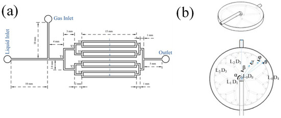
Figure 13.
Schematic diagram of tree-shaped microchannel: (a) Guo et al. (adapted from Ref. [101]), (b) Lu et al. (adapted from Ref. [104]).
However, the tree structure in nature is relatively complicated, and there is no uniform law. So, how to optimize the tree structure has become the object of research by many scholars. Lu et al. [104] optimized the circular Y-shaped liquid cooling radiator based on structural theory, shown in Figure 13b. From the branch level, temperature distribution, and pressure drop, the 1–4 level circular tree-shaped radiator was simulated. The following conclusions were drawn from the simulation results: With the increase of the number of branch stages, the peak temperature and average temperature of the Y-type cooling radiator are reduced by 28.8% and 13.5%, respectively. By comparing the pressure drop changes of the four-stage radiator, it was found that for each additional stage, the increase in pressure loss is less than 0.04 kPa.
Wang et al. [105] conducted a three-dimensional simulation analysis on the influence of the bifurcation angle of the tree-shaped microchannel heat sink on the thermal performance in Figure 14a, and then the tree-shaped microchannels at different angles and straight microchannels were compared and analyzed. It shows that reducing the bifurcation angle is beneficial to reducing the pressure drop of the microchannel heat exchanger and improving thermal performance. However, compared with the straight tube of the same heat exchange area, the pressure drop of the tree-shaped microchannel is also much smaller. Rubio-Jimenez et al. [106] performed numerical simulations on Y-shaped and ψ-shaped microchannel heat sinks of different designs, as shown in Figure 14b. The results showed that compared with the Y-shaped structure, the ψ-shaped structure has an increased heat exchange surface area, a lower thermal resistance, and a more uniform surface temperature. It was also found that bifurcation will enhance the heat transfer effect by causing interruption of the thermal boundary layer in the flow channel. Zhang et al. [107] studied the laminar fluid dynamics and thermal properties of a symmetric fractal microchannel network through numerical simulations and experiments, as shown in Figure 14c. Compared with straight and serpentine microchannels, the branched structure of the tree-shaped microchannels will produce high pressure drop and large heat transfer, while the circular branching angle can effectively reduce the pressure drop of the overall heat sink. When the aspect ratio is the same, the performance coefficient of the fractal microchannel network with two branch stages and rounded corners is the highest. Hong et al. [108] improved the right-angle fractal microchannels and proposed a fractal microchannel network construction method suitable for a rectangular channel with arbitrary aspect ratios, as shown in Figure 14d. The performance of the fractal microchannel network heat sink is compared with the performance of the parallel microchannel heat sink. The improved fractal microchannel network fluid flexibly flows and distributes, and the hot spots in the heat sink can be eliminated by locally modifying the channel size so that the improved fractal microchannel network radiator has relatively lower thermal resistance and pressure drop and is more straightforward. The temperature distribution uniformity of the microchannel is also better.
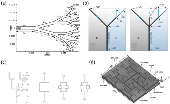
Figure 14.
Geometry optimization of fractal microchannel: (a) Wang et al. (adapted from Ref. [105]), (b) Rubio-Jimenez et al. (adapted from Ref. [106]), (c) Zhang et al. (adapted from Ref. [107]), (d) Hong et al. (adapted from Ref. [108]).
In addition to the fractal microchannel, many scholars have been inspired by the heat and mass transfer phenomenon in nature and the non-smooth surface structure of organisms and proposed microchannel heat exchangers with different bionic structures to achieve the purpose of enhancing heat transfer and reducing pressure drop.
Studies have shown that the intermittent groove structure on the shark skin surface can help the resistance of the shark when swimming, and the typical studies on geometric optimization on bionic structures as heat transfer augmentation are summarized in Table 5. Guo et al. [109] combined the spherical convex structure with the shark skin bionic structure to design a microchannel with a split spherical convex structure. When the microchannel of this kind of structure flows, the fluid hits the front end of the spherical convex structure, interrupts its thermal boundary layer, and separates the flow at the rear end, thereby enhancing heat exchange, and the oblique split channel directs the main flow to the side in the spanwise direction. The local back pressure gradient at the rear edge of the slot channel disappears, so that the uniformity is effectively improved. Experimental and numerical research on the flow and heat transfer characteristics of the new fish scale bionic microchannel bottom surface enhanced heat transfer structure was carried out by Prasenjit et al. [110], and the results showed that, compared with ordinary microchannels, the inclined fish scale structure strengthens the erosion of the upper wall by the fluid and enhances the heat transfer. In contrast, the friction factor when the inclined height of the fish scale is 0.026 is reduced by a maximum of 5%. The number of Nusselt increased by a maximum of 14%. Tan et al. [111] simulated and discussed the heat transfer performance of the cobweb-shaped microchannel and compared it with the traditional straight parallel microchannel. By analyzing the flow-boiling curves of the two models, they found that the curves of the two models were similar. Under the same mass flow and heat flux, the thermal–hydraulic performance of the cobweb-shaped microchannel is better than the traditional straight microchannel flow boiling. Especially under high heat flux, the cobweb-shaped microchannel has a higher heat transfer coefficient. The honeycomb structure of the bee is very delicate and saves materials. It is composed of countless regular hexagonal cells of the same size. Based on its special structure, Dong et al. [112] designed and processed the imitated honeycomb microchannel, which has the same area as the heating bottom. The comparison of parallel array microchannels shows that under the same other conditions, as the number of fractal layers increases, the heat transfer capacity of the imitated honeycomb structure is more than five times that of the parallel array. The pump power required by the heat exchanger is only about 1/10 of that of the parallel array heat exchanger. The special structure of airfoil fins can reduce the flow resistance very well. In 2020, Zhang et al. [113] established a microchannel heat sink model of airfoil fins structure. As an alternate arrangement in the channel, when the working fluid flows through the fins, the disturbance can be enhanced, and the special structure of the airfoil fin does not produce a large number of separated flows and vortices, thereby reducing the flow loss. Comparing the channel and the broken-line microchannel simulation of the same heat exchange area, the pressure drop loss of the airfoil fins microchannel heat exchanger under the same Re is only 54.17% that of the broken-line microchannel, and the thermal performance is increased by 25.67%.
Table 5.
Selected studies of geometric optimization on fractal geometry, bionic structures, and topology optimization on heat transfer.
Table 5.
Selected studies of geometric optimization on fractal geometry, bionic structures, and topology optimization on heat transfer.
| Reference | Type of Wall Geometry Optimizations | Research Method/ Fluid/ Flow Pattern | Heat Transfer/ Flow Resistance/ Mechanism |
|---|---|---|---|
| Wang et al. [103] | Fractal geometry | Simulation/Water/ Single-phase flow | -/ΔP/ Enhanced chaotic mixing and convection, and increased heat transfer surface area |
| Lu et al. [104] | Fractal geometry | Simulation/Water/ Single-phase flow | Tmax 28.8%, Tave13.5%/- 28.8%, Tave13.5%/-/Enhanced chaotic mixing and convection, and increased heat transfer surface area |
| Wang et al. [105] | Fractal geometry | Simulation/Water/ Single-phase flow | h/ΔP/Enhanced chaotic mixing and convection, and increased heat transfer surface area |
| Rubio-Jimenez et al. [106] | Fractal geometry | Simulation/Water/ Single-phase flow | R/ΔP/Enhanced chaotic mixing and convection, and increased heat transfer surface area |
| Zhang et al. [107] | Fractal geometry | Simulation and experiment/Water/ Single-phase flow | Nu/ΔP/ Enhanced chaotic mixing and convection, and increased heat transfer surface area |
| Hong et al. [108] | Fractal geometry | Simulation/Water/ Single-phase flow | R/ΔP/ Enhanced chaotic mixing and convection, and increased heat transfer surface area |
| Prasenjit et al. [110] | Bionic structures | Simulation and experiment/Water/ Single-phase flow | Nu14%/ ΔP /Enhanced chaotic mixing and convection, and increased heat transfer surface area |
| Dong et al. [112] | Bionic structures | Experiment/Water/ Single-phase flow | -/ΔP/ Enhanced chaotic mixing and convection |
| Zhang et al. [113] | Bionic structures | Simulation/S-CO2/ Single-phase flow | Nu/ΔP45.83%/ Enhanced chaotic mixing and convection |
| Tan et al. [114] | Topology optimization | Simulation/Water/ Single-phase flow | ΔT9.9℃/-/ Enhanced chaotic mixing and convection, and redeveloped boundary layer |
| Han et al. [115] | Topology optimization | Simulation/Water/ Single-phase flow | ΔT57.35%/ΔP/ Enhanced chaotic mixing and convection, and redeveloped thermal boundary layer |
| Pejman et al. [116] | Topology optimization | Simulation and experiment/Water and ethylene glycol/ Single-phase flow | Tmax/ΔP/Enhanced chaotic mixing and convection, and redeveloped thermal boundary layer |
Tan et al. [114] designed five bionic structures and optimized their topology, as shown in Figure 15. The simulation result of chip heat dissipation shows that the spider-netted microchannel has the best heat transfer effect due to the largest heat transfer area. According to the flow distribution and velocity uniformity of the coolant, the spider-netted microchannel is optimized to reduce the temperature difference of the heat source by a maximum of 9.9 °C compared with the straight channel, and the typical studies on geometric optimization on topology optimization as heat transfer augmentation are summarized in Table 5.
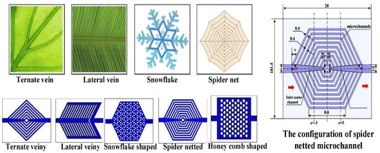
Figure 15.
Schematic diagram of microchannel topology design and optimization, (adapted from Ref. [114]).
A similar topology-optimized spider web bionic structure was made by Han et al. [115]. A spider web with three outlets and three inlets and its topology optimization model is shown in Figure 16a, and the topology optimization model (M2, M3) was designed with the goal of minimum temperature difference, average temperature, and pressure drop. The performance of the topology-optimized microchannel heat sink in pressure drop and temperature is significantly better than that of traditional spider webs, and M2 has the best performance, which is 57.35% lower than the temperature difference of M1. Pejman et al. [116] designed and optimized the topology of the microchannel of a bioinspired microvascular structure. They used a Hybrid Topology/Shape (HyTopS) optimization to filter out the seven best network configurations from fifty initial settings. Interestingly, this optimization method will not be restricted by the initial value. Even under the same conditions, different optimization designs can be obtained according to the target value, as shown in Figure 16b.
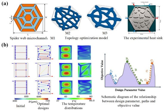
Figure 16.
Schematic diagram of microchannel topology design and optimization: (a) Han et al. (adapted from Ref. [115]), (b) Pejman et al. (adapted from Ref. [116]).
In recent decades, the application of fractal and topology optimization theory to the research of heat transfer has gradually emerged. Replicating some special structures formed in nature for a long time, such as tree-shaped, honeycomb-shaped, cobweb-shaped, etc., the microchannel has been optimized for better heat transfer. The basic principle of heat transfer enhancement is to increase the heat transfer surface area, enhance convection and chaotic mixing, and redevelop the thermal boundary layer. Thermal performance and smaller pressure drop enable microchannel technology to have better performance for cooling and heat dissipation of electronic equipment. However, most existing structures in nature are not compatible with microchannel heat sinks. How to adapt the natural structure to the flow and heat transfer of the microchannel to make it have better performance will become the direction of further research by most scholars. In addition, microchannel heat sinks are mainly used in single-phase flow, and further research is needed in flow boiling.
5.2. Double-Layer Microchannel
Single-layer microchannel heat sinks are widely used in cooling equipment, such as electronic components and large-scale integrated circuits because of their small volume per unit heat load, low requirements for refrigerants, and low cost. However, due to the relatively low flow rate of the refrigerant, it has a high temperature gradient, which makes the temperature distribution in the channel uneven. For this shortcoming, many studies have proposed the double-layer microchannel model, and the typical studies on geometric optimization on double-layer microchannel as heat transfer augmentation are summarized in Table 6.
Radwan et al. [117] used the double-layer microchannel flow-boiling heat exchange for the cooling of solar photovoltaic cells, as shown in Figure 17. Compared with single-phase flow, two-phase flow-boiling solar cells have better temperature distribution uniformity and significantly reduce the minimum temperature of the cell, thereby improving the power generation efficiency. In order to explore the influence of the flow arrangement of the microchannel heat sink on the temperature of the solar cell, an experimental study on the parallel and counter-current of the double-layer microchannel was carried out. The results showed that only at high flow rates could the parallel flow configuration be more effective in cooling than the counter-current configuration.
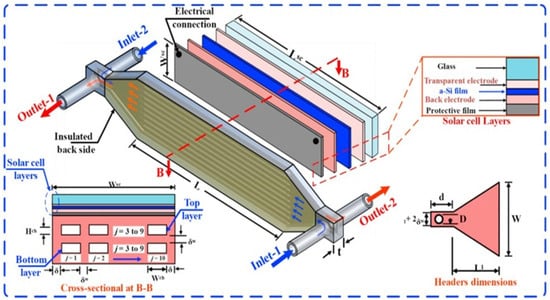
Figure 17.
Schematic diagram of double-layer microchannel (adapted from Ref. [117]).
When Wong et al. [118] compared parallel flow double-layer microchannels and countercurrent double-layer microchannels, they found that the pumping work required by the double-layer microchannel was significantly less than the single-layer microchannel. The thermal hydraulic performance of parallel flow and counter flow is complicated under different working conditions. Based on the above conclusions, Elbadawy et al. [119] used a percentage temperature reduction under different ψ and Re. To analyze and study the single-layer and double-layer microchannels compared with the single-channel design the double-channel heat transfer area increases and can absorb more heat. The use of a double-layer microchannel heat sink arranged in countercurrent flow can effectively reduce the thermal resistance of the radiator, and the maximum temperature and flow direction temperature rise of the substrate surface can also be effectively reduced. Wu et al. [120] conducted a numerical study on a double-layer silica heat sink arranged with a countercurrent flow. The study found that the inlet velocity has a great influence on the performance of the double-layer microchannel radiator. Hung et al. [121] discussed the influence of geometric parameters on the temperature distribution and pressure drop of the double-layer microchannel and compared the single-layer microchannel. When the geometric parameters are the same, the thermal resistance of single-layer and double-layer microchannels decreases with the increase of pump power, but the thermal resistance of double-layer microchannels is lower than single-layer microchannels. The research team [122] also studied the geometric parameters of the double-layer microchannel under a specific pump power to optimize the thermal performance of the radiator, as shown in Figure 18. The results showed that under specific working materials and working conditions, comparing the three initial parameters, the optimal design follows the number of channels N = 73, aspect ratio αi = 3.52 and upper channel aspect ratio αu = 7.21, and the total thermal resistance can be reduced by 52.8%.
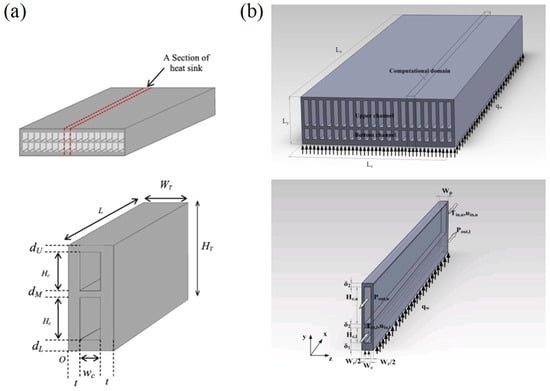
Figure 18.
Geometry optimization of double-layer microchannels: (a) Hung et al. (adapted from Ref. [121]), (b) Hung et al. (adapted from Ref. [122]).
Lin et al. [123] compared and optimized the structure of the channel number, channel height, vertical rib width, and horizontal rib thickness of the double-layer structure microchannel and gave the best structural parameters. However, they found that the bottom channel cannot optimize the performance of the double-layer microchannel because the lower temperature upstream coolant in the bottom channel will be heated by the higher temperature downstream coolant in the top channel, thereby reducing the performance of the upstream coolant. The above studies show that the double-layer microchannels arranged in countercurrent are significantly better than the single-layer microchannels, and the cooling performance of the double-layer microchannels also has a lot of room for improvement by optimizing the structure of the double-layer microchannels. Debbarma et al. [124] proposed a double-layer microchannel radiator with partial diverging channels on the top layer based on a simple double-layer microchannel, as shown in Figure 19a, and numerically simulated the new heat exchanger and simple single-layer heat exchanger by software Fluent. Due to the expansion of the interface flow area of the new channel, there is more heat convection, and the fluid distribution is improved. The pressure drop changes at the top of the smooth straight channel, and the divergent microchannel under different Reynolds number are discussed. Adding a larger flow area in the upper part of the top layer helps to significantly reduce the pressure drop, especially at a higher Reynolds number. Srivastava et al. [125] studied the bifurcation effect in multi-layer microchannels. The insertion of bifurcation plates disturbs the flow pattern and periodically interrupts the thermal boundary layer. The redevelopment of the thermal boundary layer and the fluid mixing will enhance the heat transfer. Through comparative analysis, a microchannel heat exchanger with a bifurcated structure provides a lower substrate temperature than a bifurcated structure, and the countercurrent design provides it with a more uniform temperature distribution and is compared with a microchannel without a bifurcation structure. For the channel, the double-layer microchannel with bifurcated plates reduces the thermal resistance by about 28% within the considered Reynolds number range. However, due to the existence of bifurcated plates, considering the combined effects of flow interruption and frictional resistance, the pressure drop of bifurcated microchannels is higher than that of non-branched microchannels. Especially at high flow rates, the volume of pressure drop branched microchannels is quite large.
Leng et al. [126] improved the simple double-layer structure and proposed the design of the top channel interrupted shown in Figure 19b. The improved design prevents the higher-temperature downstream coolant in the top channel from heating the lower-temperature upstream coolant in the bottom channel. In addition, a single parameter of the improved heat sink has been analyzed. When the bottom channel is long, the number of channels is large, the channel section width is relatively small, and the optimization effect of the heat exchanger performance is particularly obvious. In order to optimize the traditional rectangular double-layer microchannel radiator, Shen et al. [127] proposed a new type of X-structure double-layer microchannel heat sink, shown in Figure 19c, which can mix the flow of the double layers and change the direction of the coolant. This leads to the redevelopment of the boundary layer. Compared with a traditional straight double-layer microchannel constrained by the pressure drop loss, the convective heat characteristics have greater advantages, but the pressure drop loss increases slightly. According to the analysis of the entropy generation rate of the double-layer microchannel radiator, introducing the mixed flow X structure in the microchannel heat exchanger can significantly reduce the irreversibility of heat transfer caused by thermal changes, thereby making better use of the coolant in the microchannel heat exchange system, heat energy during flow, and heat transfer. In addition, we use the average Nusselt number and the average inlet Reynolds number as the standard to evaluate the thermal performance of parallel flow and counter flow. Compared with the parallel flow, the results of counter flow show that the convective thermal performance has a more significant enhancement.
Considering the advantages of the double-layer concept and the advantages of the porous rib design, Li et al. [128] proposed an improved design of a microchannel heat sink with high thermal performance and low pressure drop. They designed five double-layer microchannel heat sinks with porous ribs and solid ribs. The results showed that its optimal design can reduce thermal resistance by up to 14.98% and improve temperature uniformity by 58.04%. Zhai et al. [129] designed a double-layer structure with different channel geometry on each layer in Figure 19d.The upper layer is a rectangular channel, and the bottom layer is a complex channel. It is expected to improve the synergy of the velocity field and the temperature field to reduce the temperature gradient. The results showed that the double-layer heat exchanger with only optimized bottom channel structure has better temperature uniformity and lower pressure drop. The upper layer is rectangular, and the bottom layer is the heat source. For heat exchangers with complex channels, the less heat the upper layer takes away, the lower the temperature rise of the fluid, which leads to greater viscous force. In a double-layer microchannel heat sink with a complex structure, there is a longer residence time in the cavity area. Therefore, the upper rectangular channel will quickly take away the hot fluid, avoid local temperature rise, and make its heat transfer performance better.

Figure 19.
Geometry optimization of fractal microchannel: (a) Debbarma et al. (adapted from Ref. [124]), (b) Leng et al. (adapted from Ref. [126]), (c) Shen et al. (adapted from Ref. [127]), (d) Zhai et al. (adapted from Ref. [129]).
In a single-layer microchannel, the fluid flows in the same direction to absorb heat, the temperature of the refrigerant will gradually increase with flow, and its heat dissipation performance will gradually deteriorate. The uneven temperature distribution will affect the microchannels and cause huge damage to electronic devices and may cause device failure due to local overheating or reduce the reliability and life of the device due to internal thermal stress. The double-layer microchannel adopts a countercurrent flow channel structure geometric design, and the substrate of the middle layer can effectively compensate for the working fluid temperature of the upper and lower layers. This structure can effectively reduce the temperature distribution of the refrigerant and improve the heat transfer performance of the microchannel heat exchanger. In recent years, with the continuous in-depth research on double-layer microchannels, many researchers have optimized the structure of double-layer microchannels to achieve better heat transfer and lower pressure drop.
5.3. Manifold Microchannel
The manifold microchannel heat sink enhances the flow and heat transfer performance of the traditional microchannel heat sink by using the geometric optimization of the complex flow channel. The manifold microchannel heat sink changes the structure above the microchannel by adding the manifold divider. So, the microchannel is divided into many parallel manifold microchannel units, which effectively shortens the flow length of the cooling fluid and reduces the pressure drop and thermal resistance. The research results of Erp et al. [130] showed that the integration of manifold microchannels and electronic equipment can effectively improve the cooling performance, shown in Figure 20a. In the case of single-phase cooling, the coefficient of performance is increased 50 times compared with the straight microchannel, which has broad prospects in practical applications, and the typical studies on geometric optimization on manifold microchannel as heat transfer augmentation are summarized in Table 6.
Drummond et al. [131] visualized the flow boiling of the manifold microchannel two-phase flow through experiments, as shown in Figure 20b. The flow pattern of the manifold microchannel plays a decisive role in the heat transfer performance. Pan et al. [132] used numerical methods to explore the influence of the aspect ratio of cross section on the manifold microchannel. The study found that the heat sink and physical parameters of the working fluid will all affect the optimal aspect ratio. Given the criterion formula of the optimal aspect ratio, the optimal aspect ratio of water and HFE7100 is 6.6 and 16.6, respectively. Drummond et al. [133] experimentally explored the effects of three channel depths on the manifold microchannel heat sink flow boiling. Although the shallowest microchannel achieves the largest heat transfer coefficient, its thermal resistance is the largest, and the heat flux of up to 910 W/cm2 is dissipated by the deepest channel height. Luo et al. [134] conducted simulation studies on seven types of manifold microchannels with channel widths and fin widths, as shown in Figure 20c. It usually has better thermal–hydraulic performance if the channel width is larger than the fin width. In addition, different manifold arrangements have also been studied [135]. Z-type, C-type, H-type, and U-type (shapes of letters) were studied under the same conditions. Among them, the H-type and U-type manifolds can provide more uniform and lower steam fraction, so the temperature uniformity can be enhanced, and the pressure drop loss can be reduced. Lin et al. [136] extended the above work. ZU-type and HU-type (combined shapes of letters) manifold microchannels were designed and considered, as shown in Figure 20d. These two new types of manifold microchannels are recommended in single-phase flow because of their lower thermal resistance and pressure drop. Two types of the bubble flow and confined elongated bubble flow are the main observed flow pattern. For the flow-boiling situation, the thermal–hydraulic performance of the HU-type manifold microchannel heat sink is the best; the temperature distribution on the bottom surface is more uniform, and the pressure drop is also smaller.

Figure 20.
Schematic diagram of manifold microchannel: (a) Erp et al. (adapted from Ref. [130]), (b) Drummond et al. (adapted from Ref. [131]), and geometry optimization of manifold microchannel, (c) Luo et al. (adapted from Ref. [134]), (d) Lin et al. (adapted from Ref. [136]).
The above reviews of the manifold microchannels are all based on the bottom microchannels being straight channels. A new type of microchannel heat sink combining manifold and secondary channels was designed by Yang et al. [137], as shown in Figure 21a. Numerical simulation methods are used to optimize the geometric parameters of secondary oblique channels. Compared with the manifold microchannel heat sink, the new hybrid microchannel radiator can effectively reduce thermal resistance. Both secondary flow passage width λ and longer-edge length β equal one, proving to have optimal thermal–hydraulic performance. The redevelopment of the thermal boundary layer and the mixing of working fluid caused by the secondary oblique channel are the main mechanisms for improving thermal–hydraulic performance. Paniagua-Guerra et al. [138] optimized the geometry of the fractal channel manifold microchannel heat sink by the computational fluid dynamics simulation method, as shown in Figure 21b. The performance parameter (PPTR) was designed to balance pump power and thermal resistance. Interestingly, the performance of the two similarly sized designs was huge, and one of them showed the best performance. In general, the fractal channel manifold hybrid microchannel heat sink with the jet number of 64 is the best. In addition, the flow distribution of the outlet manifold shows large unevenness, so optimizing the outlet manifold micropass is also an important task.
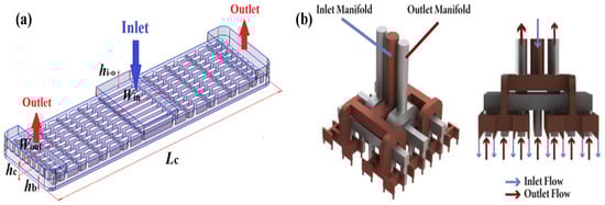
Figure 21.
Schematic diagram of complex manifold hybrid microchannel:, (a) Yang et al. (adapted from Ref. [137]), (b) Paniagua-Guerra et al. (adapted from Ref. [138]).
5.4. Other Complex Microchannel
Additive manufacturing is commonly known as 3D printing. Compared with traditional processing technology, it can produce many microstructures that can easily build complex internal structures. Ozguc et al. [139] used topology to optimize the pin-fin microchannel that can be processed by additive manufacturing technology, as shown in Figure 22a. The thermal resistance of the pin-fin microchannel under the non-uniform heating boundary condition with local hot spots is effectively reduced. Yan et al. [140] introduced channel flow and heat transfer characteristics with an X-shaped lattice core, as shown in Figure 22b. Compared with lattice frame material, the channel of the X-shaped lattice core can increase the Nusselt number by 77%. The reason for enhanced heat transfer is not the lateral and longitudinal vortices but the higher surface density. Wong et al. [27] used additive technology to design three porous lattice microstructures to enhance pool boiling heat transfer as an immersion heat sink for electronic devices, as shown in Figure 22c. Due to the increased surface area, nucleation sites, and capillary force of the porous microstructure, the orderly removal of bubbles and entry of liquids can effectively improve the heat transfer coefficient and critical heat flux density. A comparative study of the permeable-membrane microchannel heat sink made by advanced additive manufacturing technology and the manifold microchannel was conducted by Collins et al. [141], as shown in Figure 22d. The fluid absorbs heat efficiently with the wall surface in the process of passing through the permeable membrane with complex internal microstructure. Compared with the current high-efficiency manifold heat sink, the permeable-membrane microchannel heat sink can still reduce the thermal resistance 17% or even reduce the pressure drop by half, and the typical studies on geometric optimization on other complex microchannel as heat transfer augmentation are summarized in Table 6.
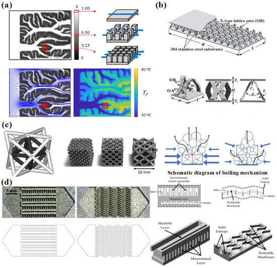
Figure 22.
Schematic diagram of complex manifold hybrid microchannel: (a) Ozguc et al. (adapted from Ref. [139]), (b) Yan et al. (adapted from Ref. [140]), (c) Wong et al. (adapted from Ref. [27]), (d) Collins et al. (adapted from Ref. [141]).
Table 6.
Selected studies of geometric optimization on complex geometry microchannel on heat transfer.
Table 6.
Selected studies of geometric optimization on complex geometry microchannel on heat transfer.
| Reference | Type of Wall Geometry Optimizations | Research Method/ Fluid/ Flow Pattern | Heat Transfer/ Flow Resistance/ Mechanism |
|---|---|---|---|
| Radwan et al. [117] | Double-layer microchannel | Experiment/Ethanol and Novec-7000/ Flow boiling | ΔT/-/ Enhanced chaotic mixing and convection |
| Wong et al. [118] | Double-layer microchannel | Simulation/Water/ Single-phase flow | R/ΔP/ Enhanced convection |
| Elbadawy et al. [119] | Double-layer microchannel | Simulation/Water/ Single-phase flow | h13.12%/ΔP10%/ Enhanced chaotic mixing and convection |
| Hung et al. [121] | Double-layer microchannel | Simulation/Water/ Single-phase flow | R/ΔP/ Enhanced convection |
| Hung et al. [122] | Double-layer microchannel | Simulation/Water/ Single-phase flow | R52.8% |
| Debbarma et al. [124] | Double-layer microchannel | Simulation/Water/ Single-phase flow | Nu/ΔP/ Provide a larger flow area |
| Srivastava et al. [125] | Double-layer microchannel | Simulation/Water/ Single-phase flow | ΔT40%, R28%, Nu/ ΔP /Enhanced chaotic mixing and convection |
| Leng et al. [126] | Double-layer microchannel | Simulation/Water/ Single-phase flow | R/ΔP/ Provide a larger flow area |
| Shen et al. [127] | Double-layer microchannel | Simulation/Water/ Single-phase flow | Nu, ΔT/ΔP/ Enhanced chaotic mixing and convection |
| Li et al. [128] | Double-layer microchannel | Simulation/Water/ Single-phase flow | ΔT58.04%, R14.98%/-/ Enhanced convection |
| Zhai et al. [129] | Double-layer microchannel | Simulation/Water/ Single-phase flow | ΔT/ΔP Provide a larger flow area |
| Erp et al. [130] | Manifold microchannel | Experiment/Water/ Single-phase flow | h, Nu/-/ Enhanced chaotic mixing and convection, secondary flow, increased heat transfer area, and redeveloped boundary layer |
| Drummond et al. [131] | Manifold microchannel | Experiment/ HFE-7100/ Flow boiling | h/-/Increasing area for expanding bubble, increasing the number of nucleate sites to enhance flow boiling |
| Drummond et al. [133] | Manifold microchannel | Experiment/ HFE-7100/ Flow boiling | h, R/-/ Increasing area for expanding bubble, increasing the number of nucleate sites to enhance flow boiling |
| Luo et al. [134] | Manifold microchannel | Simulation/ HFE-7100/ Flow boiling | R/ΔP Secondary flow, increased heat transfer area, and enhanced flow boiling |
| Luo et al. [135] | Manifold microchannel | Simulation/ HFE-7100/ Flow boiling | ΔT/ΔP/ Increasing area for expanding bubble and the number of nucleate sites to enhance flow boiling |
| Yang et al. [137] | Manifold microchannel | Simulation/Water/ Single-phase flow | R19.15%/ΔP1.91%/ Increasing area for expanding bubble, increasing the number of nucleate sites to enhance flow boiling |
| Ozguc et al. [139] | Other complex microchannel | Simulation/ Water, ethylene/ Single-phase flow | Thermal resistance/ΔP Secondary flow, increased heat transfer area, and redeveloped boundary layer |
| Yan et al. [140] | Other complex microchannel | Experiment/ Air/ Single-phase flow | Nu77%/-/ Increased heat transfer area and redeveloped boundary layer |
| Wong et al. [27] | Other complex microchannel | Experiment/ FC-72/ Flow boiling | h281%, CHF/-/ Increasing area for expanding bubble, increasing the number of nucleate sites to enhance flow boiling |
| Collins et al. [141] | Other complex microchannel | Experiment/ Water/ Single-phase flow | R17%/ΔP50%/ Enhanced chaotic mixing and convection, secondary flow, increased heat transfer area, and redeveloped boundary layer |
6. Conclusions and Future Works
This paper mainly introduces several types of microchannel geometric characteristics to enhance heat transfer and reduce channel pressure drop. As stated, it mainly includes the geometric structure of the cross section of the microchannel, the geometric structure of the wall of the microchannel, the geometric structure of the flow channel of the microchannel, and its mechanism for microchannel heat transfer. The cross section of the microchannel is introduced from the hydraulic diameter, the aspect ratio of the rectangular channel, and the cross-sectional shape. The geometric modification of the microchannel’s wall is introduced from the wave, rib and cavity, and fin and microstructures, open, interrupted, and secondary channels. The geometric modification of the flow channel is introduced from fractal geometry, bionic structures and topology optimization, double-layer microchannel, manifold microchannel, and other complex microchannels. Based on the review of the geometric characteristics of the microchannel, the following conclusions can be drawn:
- The size of the cross section of the microchannel has a profound effect on the flow and heat transfer in the microchannel. Small hydraulic diameter and a narrow and deep aspect ratio usually have better thermal performance for the single-phase flow. However, for flow boiling, the influence of geometry is complex, and bubble behavior and liquid film diffusion are the keys to heat transfer. The restrictive effect of small channels on bubble behavior may lead to greater flow resistance and deterioration of heat transfer. In addition, the cross-sectional area determines the heat transfer mechanism of flow boiling. The area decreases, and the heat transfer increases. The microchannel with the rectangular cross-section aspect ratio of one has a better heat transfer effect. However, the impact of the aspect ratio on microchannel pressure drop is not clear.
- The research on the cross-sectional shape of the microchannel generally includes the comparative study of different cross-sectional shapes and the size optimization of a certain cross-sectional shape. However, there is still a lack of comparative studies on the hydraulic and thermal properties of microchannels of different shapes after size optimization. In addition, the influence of cross-sectional geometry on microchannels is very complex which depends on its operating parameters. This indicates that it is necessary to further study the relationship between geometry and other influencing factors (such as mass flux and heat flux) to achieve the best heat transfer performance.
- The wavy microchannel and the channel geometry modification by adding ribs, cavities, pin fins, and bifurcations on the wall are introduced. These geometric modifications mainly improve the heat transfer in the straight microchannels from two aspects. On the one hand, these geometric modifications have increased the heat transfer surface area inside the microchannel. On the other hand, it can increase fluid disturbance, generate secondary flow, and promote the reconstruction of the thermal boundary layer. However, these geometric modifications increased or did not reduce the pressure drop in the channel to a certain extent compared to straight channels. The same geometric modification still needs optimization to balance pressure drop and heat transfer to meet engineering requirements.
- The open microchannel changes the flow pattern of the working fluid in the single-layer microchannel so that the working fluid has a broader flow space. Studies have shown that the open form can reduce flow resistance of the microchannel with appropriate geometric optimization. The secondary channel not only retains the advantages of the interrupted channel, the ribs, and the cavity to enhance heat transfer. It also promotes the flow between the channels to reduce the pressure drop. In addition, the geometry of the secondary channel also suppresses the instability of flow boiling. However, the new structure’s design means more adjustment and optimization of geometric parameters, such as the distribution, shape, size, and angle of the fins, etc.
- Fractal geometry and bionic structures is a structure optimized by nature. As long-term evolution, the structure has the best performance in heat and mass transfer. This natural structure is applied to a microchannel heat sink to enhance heat transfer and reduce pressure drop. However, most existing structures in nature are not compatible with microchannel heat sinks. Topology optimization can further improve the adaptability of fractal geometry and bionic structures in microchannel industrial applications.
- The design of the double-layer microchannel adjusts the flow direction of the working fluid in each microchannel layer so that the temperature gradient inside the microchannel is significantly reduced. This alleviates the problem of uneven temperature distribution in the flow field.
- The manifold structure divides the microchannel into many parallel microchannel units, which shortens the flow length of the working fluid and reduces the pressure drop. At the same time, the thermal boundary layer is difficult to develop in the microchannel, which is beneficial to increase the heat transfer coefficient and reduce the total thermal resistance. Furthermore, the temperature distribution of the manifold microchannel heat sink is more uniform.
- With the development of additive manufacturing technology, more complex microstructure microchannels can be fabricated. The manufacturing technology combines the abovementioned multiple geometric optimizations to specifically solve special industrial problems, such as non-uniform heating conditions of local hot spots.
In recent decades, a lot of research work has been carried out in the field of microchannel geometry, the heat transfer mechanism of microstructures has been well revealed, and the manufacturing applications of structures have been advanced. However, some aspects are still worth further study:
- There are many types of microchannel geometric modification, but simple geometric modification such as hydraulic diameter, cross-sectional shape, and other single geometric factors are rarely studied to ensure that other geometric factors remain constant. In recent years, this kind of weak research on the influence of basic geometric factors has received increasing attention. Many researchers have made a combination of various geometric modifications and have shown their comprehensive advantages. If the influential characteristics of a single geometric factor are clearly studied, the difficulty of combining multiple geometric modifications will be reduced.
- Secondary channels with pin fins, fractal geometry, and bionic structures, manifold microchannels have unique advantages in enhancing heat transfer. However, there are still more geometric parameters that need to be optimized to reduce the thermal resistance and pressure drop.
- The topology optimization method is effective in adjusting the parameters of the flow channel geometric structure in the microchannel. However, the research of topology optimization on the flow and heat transfer of microchannels is basically limited to single-phase flow. Flow-boiling heat transfer has broader prospects and is more complex than single-phase flow. Therefore, more topology optimization work needs to be conducted for flow boiling.
- Due to the complexity of flow-boiling heat transfer, the influence of microchannel geometry on bubbles or flow patterns should be further studied. Since different flow patterns correspond to different heat transfer mechanisms, appropriate geometry should be selected according to different flow patterns to optimize heat transfer technology.
- The geometric characteristics of microchannels are not a single factor affecting flow and heat transfer. Comprehensive consideration of the coordinated working conditions of geometry, mass flux, heat flux, working fluid, and other factors help to achieve the optimal performance of the microchannel. In addition, nanofluids, phase change materials, and other passive cooling methods combined with geometric optimization research can further improve the performance of microchannel heat sinks.
- In recent years, with the continuous advancement of processing technology, such as additive manufacturing technology, microchannels with complex geometries have become possible, and more complex microstructure microchannel experimental research should be carried out. New interesting microstructures and heat transfer mechanisms deserve to be developed. Furthermore, in practical applications, not only the thermal resistance of the microchannel heat sinks is considered, but the thermal resistance between the heat source and the microchannel heat sink is also the key to enhancing heat transfer. Therefore, collaborative design of microdevices and cooling is necessary. The embedded cooling structure may provide a broader idea for the geometric optimization of the microchannel heat sinks overall heat transfer performance.
Author Contributions
Conceptualization, H.Y. and N.M.; literature search and data analysis, H.Y., T.L. and X.Z.; writing—original draft preparation, H.Y., T.L. and X.Z., supervision, T.H. and N.M.; writing—review and editing, N.M. and T.H.; project administration, N.M.; funding acquisition, T.H. and N.M. All authors have read and agreed to the published version of the manuscript.
Funding
This research was funded by National Natural Science Foundation of China (No. 52276092), Grant-in-Aid for JSPS Fellows (No. 21F20056) and Shandong Provincial Natural Science Foundation, China (No.: ZR2020ME170).
Data Availability Statement
Not applicable.
Conflicts of Interest
The authors declare no conflict of interest.
Nomenclature
| microchannel hydraulic diameter, m | |
| thermal conductivity, W/(m·K) | |
| the Nusselt number | |
| heat transfer coefficient, W/(m2·K) | |
| temperature, °C | |
| pressure drop, Pa | |
| thermal resistance, (K/W) |
Abbreviations
| AR | aspect ratio |
| CHF | critical heat flux |
| MCHS | microchannel heat sink |
| TEC | thermoelectric cooler |
| VLSI | very-large-scale integrated |
Subscripts
| average | |
| maximum |
References
- Dai, X.; Zhou, W.; Yang, S.; Sun, F.; Qian, J.; He, M.; Chen, Q. Microchannel process for phenol production via the cleavage of cumene hydroperoxide. Chem. Eng. Sci. 2019, 199, 398–404. [Google Scholar] [CrossRef]
- Strumpf, H.J.; Mirza, Z. Development of a Microchannel Heat Exchanger for Aerospace Applications. In Proceedings of the ASME 2012 10th International Conference on Nanochannels, Microchannels, and Minichannels (ICNMM), Rio Grande, PR, USA, 8–12 July 2012. [Google Scholar]
- Abo-Zahhad, E.M.; Ookawara, S.; Radwan, A.; Elkady, M.; El-Shazly, A.H. Optimization of stepwise varying width microchannel heat sink for high heat flux applications. Case Stud. Therm. Eng. 2020, 18, 100587. [Google Scholar] [CrossRef]
- Sharma, C.S.; Tiwari, M.K.; Poulikakos, D. A simplified approach to hotspot alleviation in microprocessors. Appl. Therm. Eng. 2016, 93, 1314–1323. [Google Scholar] [CrossRef]
- Li, X.; Xuan, Y. Self-adaptive cooling of chips with unevenly distributed high heat fluxes. Appl. Therm. Eng. 2022, 202, 117913. [Google Scholar] [CrossRef]
- Lu, Y.; Guo, Z.; Gong, Y.; Zhang, T.; Huang, Y.; Niu, F. Optimal study of swordfish fin microchannel heat exchanger for the next generation nuclear power conversion system of lead-based reactor. Ann. Nucl. Energy 2022, 165, 108679. [Google Scholar] [CrossRef]
- Prabhakar, A.; Verma, D.; Dhwaj, A.; Mukherji, S. Microchannel integrated tapered and tapered-bend waveguides, for proficient, evanescent-field absorbance based, on-chip, chemical and biological sensing operations. Sens. Actuators B Chem. 2021, 332, 129455. [Google Scholar] [CrossRef]
- Redo, M.A.; Jeong, J.; Giannetti, N.; Enoki, K.; Yamaguchi, S.; Saito, K.; Kim, H. Characterization of two-phase flow distribution in microchannel heat exchanger header for air-conditioning system. Exp. Therm. Fluid Sci. 2019, 106, 183–193. [Google Scholar] [CrossRef]
- Tuckerman, D.; Pease, R. High-performance heat sinking for VLSI. IEEE Electron. Device Lett. 1981, 2, 126–129. [Google Scholar] [CrossRef]
- Hajialibabaei, M.; Saghir, Z. A Critical Review of the Straight and Wavy Microchannel Heat Sink and the Application in Lithium-Ion Battery Thermal Management. SSRN Electron. J. 2022. preprint article. [Google Scholar] [CrossRef]
- Andhare, R.S.; Shooshtari, A.; Dessiatoun, S.; Ohadi, M. Heat transfer and pressure drop characteristics of a flat plate manifold microchannel heat exchanger in counter flow configuration. Appl. Therm. Eng. 2016, 96, 178–189. [Google Scholar] [CrossRef]
- Hao, X.; Peng, B.; Xie, G.; Chen, Y. Efficient on-chip hotspot removal combined solution of thermoelectric cooler and mini-channel heat sink. Appl. Therm. Eng. 2016, 100, 170–178. [Google Scholar] [CrossRef]
- Zhu, Y.; Antao, D.; Chu, K.; Chen, S.; Hendricks, T.; Zhang, T.; Wang, E. Surface Structure Enhanced Microchannel Flow Boiling. J. Heat Transf. 2016, 138, 091501. [Google Scholar] [CrossRef]
- Green, C.E.; Kottke, P.A.; Sarvey, T.E.; Fedorov, A.G.; Joshi, Y.K.; Bakir, M.S. Performance and Integration Implications of Addressing Localized Hotspots Through Two Approaches: Clustering of Micro Pin-Fins and Dedicated Microgap Coolers. In Proceedings of the ASME 2015 International Technical Conference and Exhibition on Packaging and Integration of Electronic and Photonic Microsystems, San Francisco, CA, USA, 6–9 July 2015. [Google Scholar]
- Tang, J.X.; Liu, Y.; Huang, B.; Xu, D. Enhanced heat transfer coefficient of flow boiling in microchannels through expansion areas. Int. J. Therm. Sci. 2022, 177, 107573. [Google Scholar] [CrossRef]
- Ramesh, K.; Sharma, T.K.; Rao, G.A. Latest Advancements in Heat Transfer Enhancement in the Micro-channel Heat Sinks: A Review. Arch. Comput. Methods Eng. 2020, 28, 3135–3165. [Google Scholar] [CrossRef]
- Toghraie, D.; Mashayekhi, R.; Niknejadi, M.; Arasteh, H. Hydrothermal performance analysis of various surface roughness configurations in trapezoidal microchannels at slip flow regime. Chin. J. Chem. Eng. 2020, 28, 1522–1532. [Google Scholar] [CrossRef]
- Liu, Y.; Xu, G.; Sun, J.; Li, H. Investigation of the roughness effect on flow behavior and heat transfer characteristics in microchannels. Int. J. Heat Mass Transf. 2015, 83, 11–20. [Google Scholar] [CrossRef]
- Attalla, M.; Maghrabie, H.M.; Specht, E. An experimental investigation on fluid flow and heat transfer of rough mini-channel with rectangular cross section. Exp. Therm. Fluid Sci. 2016, 75, 199–210. [Google Scholar] [CrossRef]
- Guo, L.; Xu, H.; Gong, L. Influence of wall roughness models on fluid flow and heat transfer in microchannels. Appl. Therm. Eng. 2015, 84, 399–408. [Google Scholar] [CrossRef]
- Wan, Z.; Lin, Q.; Wang, X.; Tang, Y. Flow characteristics and heat transfer performance of half-corrugated microchannels. Appl. Therm. Eng. 2017, 123, 1140–1151. [Google Scholar] [CrossRef]
- Xu, S.; Yang, L.; Li, Y.; Wu, Y.; Hu, X. Experimental and numerical investigation of heat transfer for two-layered microchannel heat sink with non-uniform heat flux conditions. Heat Mass Transf. 2016, 52, 1755–1763. [Google Scholar] [CrossRef]
- Lorenzini, G.; Biserni, C.; Rocha, L. Constructal design of non-uniform X-shaped conductive pathways for cooling. Int. J. Therm. Sci. 2013, 71, 140–147. [Google Scholar] [CrossRef]
- Chamkha, A.; Molana, M.; Rahnama, A.; Ghadami, F. On the nanofluids applications in microchannels: A comprehensive review. Powder Technol. 2018, 332, 287–322. [Google Scholar] [CrossRef]
- Sidik, N.A.; Muhamad, M.N.; Japar, W.M.; Rasid, Z.A. An overview of passive techniques for heat transfer augmentation in microchannel heat sink. Int. Commun. Heat Mass Transf. 2017, 88, 74–83. [Google Scholar] [CrossRef]
- Markal, B.; Aydin, O.; Avci, M. Effect of hydraulic diameter on flow boiling in rectangular microchannels. Heat Mass Transf. 2019, 55, 1033–1044. [Google Scholar] [CrossRef]
- Wong, K.K.; Leong, K.C. Saturated pool boiling enhancement using porous lattice structures produced by Selective Laser Melting. Int. J. Heat Mass Transf. 2018, 121, 46–63. [Google Scholar] [CrossRef]
- Chai, L.; Xia, G.; Wang, H.S. Numerical study of laminar flow and heat transfer in microchannel heat sink with offset ribs on sidewalls. Appl. Therm. Eng. 2016, 92, 32–41. [Google Scholar] [CrossRef]
- Chai, L.; Wang, L.; Bai, X. Thermohydraulic performance of microchannel heat sinks with triangular ribs on sidewalls—Part 1: Local fluid flow and heat transfer characteristics. Int. J. Heat Mass Transf. 2018, 127, 1124–1137. [Google Scholar] [CrossRef]
- Chai, L.; Wang, L.; Bai, X. Thermohydraulic performance of microchannel heat sinks with triangular ribs on sidewalls—Part 2: Average fluid flow and heat transfer characteristics. Int. J. Heat Mass Transf. 2018, 128, 634–648. [Google Scholar] [CrossRef]
- Kumar, P. Numerical investigation of fluid flow and heat transfer in trapezoidal microchannel with groove structure. Int. J. Therm. Sci. 2019, 136, 33–43. [Google Scholar] [CrossRef]
- Xie, G.; Zhao, L.; Dong, Y.; Li, Y.; Zhang, S.; Yang, C. Hydraulic and Thermal Performance of Microchannel Heat Sink Inserted with Pin Fins. Micromachines 2021, 12, 245. [Google Scholar] [CrossRef]
- Lin, L.; Zhao, J.; Lu, G.; Wang, X.D.; Yan, W.M. Heat transfer enhancement in microchannel heat sink by wavy channel with changing wavelength/amplitude. Int. J. Therm. Sci. 2017, 118, 423–434. [Google Scholar] [CrossRef]
- Shamsi, M.; Akbari, O.A.; Marzban, A.; Toghraie, D.; Mashayekhi, R. Increasing heat transfer of non-Newtonian nanofluid in rectangular microchannel with triangular ribs. Phys. E Low-Dimens. Syst. Nanostructures 2017, 93, 167–178. [Google Scholar] [CrossRef]
- Xie, G.; Shen, H.; Wang, C. Parametric study on thermal performance of microchannel heat sinks with internal vertical Y-shaped bifurcations. Int. J. Heat Mass Transf. 2015, 90, 948–958. [Google Scholar] [CrossRef]
- Shi, X.; Li, S.; Mu, Y.; Yin, B. Geometry parameters optimization for a microchannel heat sink with secondary flow channel. Int. Commun. Heat Mass Transf. 2019, 104, 89–100. [Google Scholar] [CrossRef]
- Law, M.; Lee, P. A comparative study of experimental flow boiling heat transfer and pressure characteristics in straight- and oblique-finned microchannels. Int. J. Heat Mass Transf. 2015, 85, 797–810. [Google Scholar] [CrossRef]
- Zhai, Y.L.; Xia, G.D.; Liu, X.F.; Li, Y.F. Heat transfer in the microchannels with fan-shaped reentrant cavities and different ribs based on field synergy principle and entropy generation analysis. Int. J. Heat Mass Transf. 2014, 68, 224–233. [Google Scholar] [CrossRef]
- Ong, C.L.; Thome, J. Macro-to-microchannel transition in two-phase flow: Part 1—Two-phase flow patterns and film thickness measurements. Exp. Therm. Fluid Sci. 2011, 35, 37–47. [Google Scholar] [CrossRef]
- Kandlikar, S.; Steinke, M.; Tian, S.; Campbell, L. High-Speed photographic observation of flow boiling of water in parallel mini-channels. In Proceedings of the 35th National Heat Transfer Conference, Anaheim, CA, USA, 10–12 June 2001. [Google Scholar]
- Lee, P.S.; Garimella, S.V.; Liu, D. Investigation of heat transfer in rectangular microchannels. Int. J. Heat Mass Transf. 2005, 48, 1688–1704. [Google Scholar] [CrossRef]
- Tiwari, N.; Moharana, M.K. Effect of conjugate heat transfer in single-phase laminar flow through partially heated microtubes. Sādhanā 2021, 46, 28. [Google Scholar] [CrossRef]
- Sadaghiani, A.K.; Koşar, A. Numerical and experimental investigation on the effects of diameter and length on high mass flux subcooled flow boiling in horizontal microtubes. Int. J. Heat Mass Transf. 2016, 92, 824–837. [Google Scholar] [CrossRef]
- Yang, K.; Jeng, Y.; Huang, C.; Wang, C. Heat Transfer and Flow Pattern Characteristics for HFE-7100 within Microchannel Heat Sinks. Heat Transf. Eng. 2011, 32, 697–704. [Google Scholar] [CrossRef]
- Tiwari, N.; Moharana, M.K. Conjugate heat transfer analysis of liquid-vapor two phase flow in a microtube: A numerical investigation. Int. J. Heat Mass Transf. 2019, 142, 118427. [Google Scholar] [CrossRef]
- Matin, M.H.; Moghaddam, S. Thin liquid films formation and evaporation mechanisms around elongated bubbles in rectangular cross-section microchannels. Int. J. Heat Mass Transf. 2020, 163, 120474. [Google Scholar] [CrossRef]
- Naphon, P.; Khonseur, O. Study on the convective heat transfer and pressure drop in the micro-channel heat sink. Int. Commun. Heat Mass Transf. 2009, 36, 39–44. [Google Scholar] [CrossRef]
- Xie, X.; Liu, Z.; He, Y.; Tao, W. Numerical study of laminar heat transfer and pressure drop characteristics in a water-cooled minichannel heat sink. Appl. Therm. Eng. 2009, 29, 64–74. [Google Scholar] [CrossRef]
- Wang, Y.; Sefiane, K. Effects of heat flux, vapour quality, channel hydraulic diameter on flow boiling heat transfer in variable aspect ratio micro-channels using transparent heating. Int. J. Heat Mass Transf. 2012, 55, 2235–2243. [Google Scholar] [CrossRef]
- Lee, J.; Mudawar, I. Fluid flow and heat transfer characteristics of low temperature two-phase micro-channel heat sinks—Part 1: Experimental methods and flow visualization results. Int. J. Heat Mass Transf. 2008, 51, 4315–4326. [Google Scholar] [CrossRef]
- Lee, J.; Mudawar, I. Fluid flow and heat transfer characteristics of low temperature two-phase micro-channel heat sinks—Part 2. Subcooled boiling pressure drop and heat transfer. Int. J. Heat Mass Transf. 2008, 51, 4327–4341. [Google Scholar] [CrossRef]
- Harirchian, T.; Garimella, S. Microchannel size effects on local flow boiling heat transfer to a dielectric fluid. Int. J. Heat Mass Transf. 2008, 51, 3724–3735. [Google Scholar] [CrossRef]
- Harirchian, T.; Garimella, S.V. The critical role of channel cross-sectional area in microchannel flow boiling heat transfer. Int. J. Multiph. Flow 2009, 35, 904–913. [Google Scholar] [CrossRef]
- Markal, B.; Aydin, O.; Avci, M. Effect of aspect ratio on saturated flow boiling in microchannels. Int. J. Heat Mass Transf. 2016, 93, 130–143. [Google Scholar] [CrossRef]
- Fu, B.R.; Lee, C.Y.; Pan, C. The effect of aspect ratio on flow boiling heat transfer of hfe-7100 in a microchannel heat sink. Int. J. Heat Mass Transf. 2013, 58, 53–61. [Google Scholar] [CrossRef]
- Candan, A.; Markal, B.; Aydin, O.; Avci, M. Saturated flow boiling characteristics in single rectangular minichannels: Effect of aspect ratio. Exp. Heat Transf. 2018, 31, 531–551. [Google Scholar] [CrossRef]
- Wang, H.; Chen, Z.; Gao, J. Influence of geometric parameters on flow and heat transfer performance of micro-channel heat sinks. Appl. Therm. Eng. 2016, 107, 870–879. [Google Scholar] [CrossRef]
- Jing, D.; He, L. Numerical studies on the hydraulic and thermal performances of microchannels with different cross-sectional shapes. Int. J. Heat Mass Transf. 2019, 143, 118604. [Google Scholar] [CrossRef]
- Salimpour, M.; Sharifhasan, M.; Shirani, E. Constructal Optimization of Microchannel Heat Sinks with Noncircular Cross Sections. Heat Transf. Eng. 2013, 34, 863–874. [Google Scholar] [CrossRef]
- Luo, W.; He, J.; Luo, B.; Xu, Y.; Lin, M. Numerical Study on the Effect of Cross-Sectional Shape of Microchannels on Flow Boiling. J. Xi’an Jiaotong Univ. 2019, 53, 101–111. (In Chinese) [Google Scholar]
- Sempértegui-Tapia, D.F.; Ribatski, G. The effect of the cross-sectional geometry on saturated flow boiling heat transfer in horizontal micro-scale channels. In Proceedings of the IV Journeys in Multiphase Flows (JEM2015), Campinas, Brazil, 23–27 March 2015. [Google Scholar]
- Goodarzi, M.; Tlili, I.; Tian, Z.; Safaei, M. Efficiency assessment of using graphene nanoplatelets-silver/water nanofluids in microchannel heat sinks with different cross-sections for electronics cooling. Int. J. Numer. Methods Heat Fluid Flow 2019, 30, 347–372. [Google Scholar] [CrossRef]
- Chen, Y.; Zhang, C.; Shi, M.; Wu, J. Three-dimensional numerical simulation of heat and fluid flow in noncircular microchannel heat sinks. Int. Commun. Heat Mass Transf. 2009, 36, 917–920. [Google Scholar] [CrossRef]
- Raj, S.; Shukla, A.; Pathak, M.; Khan, M.K. A novel stepped microchannel for performance enhancement in flow boiling. Int. J. Heat Mass Transf. 2019, 144, 118611. [Google Scholar] [CrossRef]
- Khan, A.; Kim, S.; Kim, K. Multi-Objective Optimization of an Inverse Trapezoidal-Shaped Microchannel. Heat Transf. Eng. 2016, 37, 571–580. [Google Scholar] [CrossRef]
- Mohammed, H.A.; Gunnasegaran, P.; Shuaib, N.H. Numerical simulation of heat transfer enhancement in wavy microchannel heat sink. Int. Commun. Heat Mass Transf. 2011, 38, 63–68. [Google Scholar] [CrossRef]
- Tiwari, N.; Moharana, M.K. Numerical Study of Thermal Enhancement in Modified Raccoon Microchannels. Heat Transf. Res. 2019, 50, 519–543. [Google Scholar] [CrossRef]
- Tiwari, N.; Moharana, M.K. Conjugate effect on flow boiling instability in wavy microchannel. Int. J. Heat Mass Transf. 2021, 166, 120791. [Google Scholar] [CrossRef]
- Bhuva, V.J.; Jani, J.P.; Patel, A.; Tiwari, N. Effect of bubble coalescence on two-phase flow boiling heat transfer in raccoon microchannel—A numerical study. Int. J. Heat Mass Transf. 2022, 182, 121943. [Google Scholar] [CrossRef]
- Sui, Y.; Teo, C.J.; Lee, P.S.; Chew, Y.T.; Shu, C. Fluid flow and heat transfer in wavy microchannels. Int. J. Heat Mass Transf. 2010, 53, 2760–2772. [Google Scholar] [CrossRef]
- Xu, M.; Lu, H.; Gong, L.; Chai, J.; Duan, X. Parametric numerical study of the flow and heat transfer in microchannel with dimples. Int. Commun. Heat Mass Transf. 2016, 76, 348–357. [Google Scholar] [CrossRef]
- Chai, L.; Xia, G.; Wang, H.S. Parametric study on thermal and hydraulic characteristics of laminar flow in microchannel heat sink with fan-shaped ribs on sidewalls—Part 1: Heat transfer. Int. J. Heat Mass Transf. 2016, 97, 1069–1080. [Google Scholar] [CrossRef]
- Chai, L.; Xia, G.; Wang, H.S. Parametric study on thermal and hydraulic characteristics of laminar flow in microchannel heat sink with fan-shaped ribs on sidewalls—Part 2: Pressure drop. Int. J. Heat Mass Transf. 2016, 97, 1081–1090. [Google Scholar] [CrossRef]
- Chai, L.; Xia, G.; Wang, H.S. Parametric study on thermal and hydraulic characteristics of laminar flow in microchannel heat sink with fan-shaped ribs on sidewalls—Part 3: Performance evaluation. Int. J. Heat Mass Transf. 2016, 97, 1091–1101. [Google Scholar] [CrossRef]
- Chai, L.; Xia, G.; Zhou, M.; Li, J. Numerical simulation of fluid flow and heat transfer in a microchannel heat sink with offset fan-shaped reentrant cavities in sidewall. Int. Commun. Heat Mass Transf. 2011, 38, 577–584. [Google Scholar] [CrossRef]
- Li, Y.; Xia, G.; Jia, Y.; Cheng, Y.; Wang, J. Experimental investigation of flow boiling performance in microchannels with and without triangular cavities—A comparative study. Int. J. Heat Mass Transf. 2017, 108, 1511–1526. [Google Scholar] [CrossRef]
- Chai, L.; Xia, G.; Wang, L.; Zhou, M.; Cui, Z. Heat transfer enhancement in microchannel heat sinks with periodic expansion–constriction cross-sections. Int. J. Heat Mass Transf. 2013, 62, 741–751. [Google Scholar] [CrossRef]
- Xia, G.; Zhai, Y.; Cui, Z. Numerical investigation of thermal enhancement in a micro heat sink with fan-shaped reentrant cavities and internal ribs. Appl. Therm. Eng. 2013, 58, 52–60. [Google Scholar] [CrossRef]
- Deng, D.; Wan, W.; Qin, Y.; Zhang, J.; Chu, X. Flow boiling enhancement of structured microchannels with micro pin fins. Int. J. Heat Mass Transf. 2017, 105, 338–349. [Google Scholar] [CrossRef]
- Rajalingam, A.; Chakraborty, S. Effect of shape and arrangement of micro-structures in a microchannel heat sink on the thermo-hydraulic performance. Appl. Therm. Eng. 2021, 190, 116755. [Google Scholar]
- Ahmadian-Elmi, M.; Mashayekhi, A.; Nourazar, S.S.; Vafai, K. A comprehensive study on parametric optimization of the pin-fin heat sink to improve its thermal and hydraulic characteristics. Int. J. Heat Mass Transf. 2021, 180, 121797. [Google Scholar] [CrossRef]
- Zeng, L.; Deng, D.; Zhong, N.; Zheng, G. Heat transfer and flow characteristics in microchannel heat sink with open-ring pin fins. Int. J. Mech. Sci. 2021, 200, 106445. [Google Scholar] [CrossRef]
- Xia, G.; Jia, Y.; Li, Y.; Ma, D.; Cai, B. Numerical simulation and multiobjective optimization of a microchannel heat sink with arc-shaped grooves and ribs. Numer. Heat Transf. Part A Appl. 2016, 70, 1041–1055. [Google Scholar] [CrossRef]
- Xia, G.; Chai, L.; Wang, H.; Zhou, M.; Cui, Z. Optimum thermal design of microchannel heat sink with triangular reentrant cavities. Appl. Therm. Eng. 2011, 31, 1208–1219. [Google Scholar] [CrossRef]
- Beng, S.W.; Japar, W.A. Numerical analysis of heat and fluid flow in microchannel heat sink with triangular cavities. J. Adv. Res. Fluid Mech. Therm. Sci. 2017, 34, 1–8. [Google Scholar]
- Tiwari, N.; Moharana, M.K. Comparative study of conjugate heat transfer in a single-phase flow in wavy and raccoon microchannels. Int. J. Numer. Methods Heat Fluid Flow 2019, 30, 3791–3825. [Google Scholar] [CrossRef]
- Doshi, S.; Kashyap, G.; Tiwari, N. Thermo-hydraulic and entropy generation investigation of nano-encapsulated phase change material (NEPCM) slurry in hybrid wavy microchannel. Int. J. Numer. Methods Heat Fluid Flow 2022, 32, 3161–3190. [Google Scholar] [CrossRef]
- Foong, A.; Ramesh, N.; Chandratilleke, T. Laminar convective heat transfer in a microchannel with internal longitudinal fins. Int. J. Therm. Sci. 2009, 48, 1908–1913. [Google Scholar] [CrossRef]
- Xia, G.; Cheng, Y.; Cheng, L.; Li, Y. Heat Transfer Characteristics and Flow Visualization during Flow Boiling of Acetone in Semi-Open Multi-Microchannels. Heat Transf. Eng. 2019, 40, 1349–1362. [Google Scholar] [CrossRef]
- Yin, L.; Jiang, P.; Xu, R.; Wang, W.; Jia, L. Visualization of flow patterns and bubble behavior during flow boiling in open microchannels. Int. Commun. Heat Mass Transf. 2017, 85, 131–138. [Google Scholar] [CrossRef]
- Yin, L.; Jiang, P.; Xu, R.; Hu, H.; Jia, L. Heat transfer and pressure drop characteristics of water flow boiling in open microchannels. Int. J. Heat Mass Transf. 2019, 137, 204–215. [Google Scholar] [CrossRef]
- Balasubramanian, K.; Krishnan, R.; Suresh, S. Spatial orientation effects on flow boiling performances in open microchannels heat sink configuration under a wide range of mass fluxes. Exp. Therm. Fluid Sci. 2018, 99, 392–406. [Google Scholar] [CrossRef]
- Bhandari, P.; Prajapati, Y. Thermal performance of open microchannel heat sink with variable pin fin height. Int. J. Therm. Sci. 2021, 159, 106609. [Google Scholar] [CrossRef]
- Xu, J.; Song, Y.; Zhang, W.; Zhang, H.; Gan, Y. Numerical simulations of interrupted and conventional microchannel heat sinks. Int. J. Heat Mass Transf. 2008, 51, 5906–5917. [Google Scholar] [CrossRef]
- Chai, L.; Xia, G.; Zhou, M.; Li, J.; Qi, J. Optimum thermal design of interrupted microchannel heat sink with rectangular ribs in the transverse microchambers. Appl. Therm. Eng. 2013, 51, 880–889. [Google Scholar] [CrossRef]
- Prajapati, Y.; Pathak, M.; Khan, M.K. Bubble dynamics and flow boiling characteristics in three different microchannel configurations. Int. J. Therm. Sci. 2017, 112, 371–382. [Google Scholar] [CrossRef]
- Ghani, I.A.; Sidik, N.; Mamat, R.; Najafi, G.; Ken, T.; Asako, Y.; Japar, W.A. Heat Transfer Enhancement in Microchannel Heat Sink Using Hybrid Technique of Ribs and Secondary Channels. Int. J. Heat Mass Transf. 2017, 114, 640–655. [Google Scholar] [CrossRef]
- Wan, W.; Deng, D.; Huang, Q.; Zeng, T.; Huang, Y. Experimental study and optimization of pin fin shapes in flow boiling of micro pin fin heat sinks. Appl. Therm. Eng. 2017, 114, 436–449. [Google Scholar] [CrossRef]
- Law, M.; Kanargi, O.B.; Lee, P.S. Effects of varying oblique angles on flow boiling heat transfer and pressure characteristics in oblique-finned microchannels. Int. J. Heat Mass Transf. 2016, 100, 646–660. [Google Scholar] [CrossRef]
- Huang, S.; Jin, Z.; Liang, G.; Duan, X. Thermal performance and structure optimization for slotted microchannel heat sink. Appl. Therm. Eng. 2017, 115, 1266–1276. [Google Scholar] [CrossRef]
- Guo, R.; Fu, T.; Zhu, C.; Yin, Y.; Ma, Y. Hydrodynamics and mass transfer of gas-liquid flow in a tree-shaped parallel microchannel with T-type bifurcations. Chem. Eng. J. 2019, 373, 1203–1211. [Google Scholar] [CrossRef]
- Yu, X. Experimental and Numerical Study on Fractal Tree-like Microchannels. Master’s Thesis, Huazhong University of Science and Technology, Wuhan, China, 2012. (In Chinese). [Google Scholar]
- Wang, X.; Mujumdar, A.; Yap, C. Thermal characteristics of tree-shaped microchannel nets for cooling of a rectangular heat sink. Int. J. Therm. Sci. 2006, 45, 1103–1112. [Google Scholar] [CrossRef]
- Lu, Z.; Zhang, K.; Liu, J.; Li, F. Effect of branching level on the performance of constructal theory based Y-shaped liquid cooling heat sink. Appl. Therm. Eng. 2020, 168, 114824. [Google Scholar] [CrossRef]
- Wang, X.; Mujumdar, A.S.; Yap, C. Effect of bifurcation angle in tree-shaped microchannel networks. J. Appl. Phys. 2007, 102, 73530. [Google Scholar] [CrossRef]
- Rubio-Jimenez, C.; Hernández-Guerrero, A.; Cervantes, J.; Lorenzini-Gutierrez, D.; Gonzalez-Valle, C.U. CFD study of constructal microchannel networks for liquid-cooling of electronic devices. Appl. Therm. Eng. 2016, 95, 374–381. [Google Scholar] [CrossRef]
- Zhang, C.; Lian, Y.; Yu, X.; Liu, W.; Teng, J.; Xu, T.; Hsu, C.; Chang, Y.; Greif, R. Numerical and experimental studies on laminar hydrodynamic and thermal characteristics in fractal-like microchannel networks. Part B: Investigations on the performances of pressure drop and heat transfer. Int. J. Heat Mass Transf. 2013, 66, 939–947. [Google Scholar] [CrossRef]
- Hong, F.; Cheng, P.; Ge, H.; Joo, G.T. Conjugate heat transfer in fractal-shaped microchannel network heat sink for integrated microelectronic cooling application. Int. J. Heat Mass Transf. 2007, 50, 4986–4998. [Google Scholar] [CrossRef]
- Guo, D.Z.; Huang, X.Y.; Li, P. Flow structure and heat transfer characteristics of microchannel heat sinks with split protrusion. Chin. Sci. Bull. 2019, 64, 1526–1534. (In Chinese) [Google Scholar] [CrossRef]
- Dey, P.; Hedau, G.; Saha, S.K. Experimental and numerical investigations of fluid flow and heat transfer in a bioinspired surface enriched microchannel. Int. J. Therm. Sci. 2019, 135, 44–60. [Google Scholar] [CrossRef]
- Tan, H.; Chen, J.; Wang, M.; Du, P. Experimental Study of Flow Boiling Heat Transfer in Spider Netted Microchannel for Chip Cooling. In Proceedings of the World Congress on Engineering (WCE), London, UK, 4–6 July 2018. [Google Scholar]
- Dong, T.; Chen, Y.S.; Yang, Z.C.; Bi, Q.C.; Wu, H.L.; Zheng, G.P. Flow and heat transfer in comby fractal microchannel network. J. Chem. Ind. Eng. 2005, 56, 1619–1625. (In Chinese) [Google Scholar]
- Zhang, T.Y.; Guo, Z.P.; Niu, F.L.; Huang, Y.P. Heat Transfer Characteristic of Airfoil Microchannel Efficient and Compact Heat Exchanger. At. Energy Sci. Technol. 2020, 54, 1780–1786. (In Chinese) [Google Scholar]
- Tan, H.; Wu, L.; Wang, M.; Yang, Z.; Du, P. Heat transfer improvement in microchannel heat sink by topology design and optimization for high heat flux chip cooling. Int. J. Heat Mass Transf. 2019, 129, 681–689. [Google Scholar] [CrossRef]
- Han, X.; Liu, H.; Xie, G.; Sang, L.; Zhou, J. Topology optimization for spider web heat sinks for electronic cooling. Appl. Therm. Eng. 2021, 195, 117154. [Google Scholar] [CrossRef]
- Pejman, R.; Aboubakr, S.H.; Martin, W.H.; Devi, U.; Tan, M.H.; Patrick, J.F.; Najafi, A.R. Gradient-based hybrid topology/shape optimization of bioinspired microvascular composites. Int. J. Heat Mass Transf. 2019, 144, 118606. [Google Scholar] [CrossRef]
- Radwan, A.; Ookawara, S.; Ahmed, M. Thermal management of concentrator photovoltaic systems using two-phase flow boiling in double-layer microchannel heat sinks. Appl. Energy 2019, 241, 404–419. [Google Scholar] [CrossRef]
- Wong, K.; Muezzin, F.N. Heat transfer of a parallel flow two-layered microchannel heat sink. Int. Commun. Heat Mass Transf. 2013, 49, 136–140. [Google Scholar] [CrossRef]
- Elbadawy, I.; Fayed, M. Reliability of Al2O3 nanofluid concentration on the heat transfer augmentation and resizing for single and double stack microchannels. Alex. Eng. J. 2020, 59, 1771–1785. [Google Scholar] [CrossRef]
- Wu, J.; Zhao, J.; Tseng, K. Parametric study on the performance of double-layered microchannels heat sink. Energy Convers. Manag. 2014, 80, 550–560. [Google Scholar] [CrossRef]
- Hung, T.; Yan, W.; Li, W. Analysis of heat transfer characteristics of double-layered microchannel heat sink. Int. J. Heat Mass Transf. 2012, 55, 3090–3099. [Google Scholar] [CrossRef]
- Hung, T.; Yan, W.; Wang, X.; Huang, Y. Optimal design of geometric parameters of double-layered microchannel heat sinks. Int. J. Heat Mass Transf. 2012, 55, 3262–3272. [Google Scholar] [CrossRef]
- Lin, L.; Chen, Y.; Zhang, X.; Wang, X. Optimization of geometry and flow rate distribution for double-layer microchannel heat sink. Int. J. Therm. Sci. 2014, 78, 158–168. [Google Scholar] [CrossRef]
- Debbarma, D.; Pandey, K.M.; Paul, A. Numerical study on double layered micro channel heat sink with partly diverged channel in top layer. Mater. Today Proc. 2020, 45, 6542–6546. [Google Scholar] [CrossRef]
- Srivastava, P.; Patel, R.I.; Dewan, A. A study on thermal characteristics of double-layered microchannel heat sink: Effects of bifurcation and flow configuration. Int. J. Therm. Sci. 2021, 162, 106791. [Google Scholar] [CrossRef]
- Leng, C.; Wang, X.; Wang, T. An improved design of double-layered microchannel heat sink with truncated top channels. Appl. Therm. Eng. 2015, 79, 54–62. [Google Scholar] [CrossRef]
- Shen, H.; Xie, G.; Wang, C. Thermal performance and entropy generation of novel X-structured double layered microchannel heat sinks. J. Taiwan Inst. Chem. Eng. 2020, 111, 90–104. [Google Scholar] [CrossRef]
- Li, X.Y.; Wang, S.L.; Wang, X.D.; Wang, T.H. Selected porous-ribs design for performance improvement in double-layered microchannel heat sinks. Int. J. Therm. Sci. 2019, 137, 616–626. [Google Scholar] [CrossRef]
- Zhai, Y.; Li, Z.; Wang, H.; Xu, J. Thermodynamic analysis of the effect of channel geometry on heat transfer in double-layered microchannel heat sinks. Energy Convers. Manag. 2017, 143, 431–439. [Google Scholar] [CrossRef]
- Erp, R.V.; Soleimanzadeh, R.; Nela, L.; Kampitsis, G.; Matioli, E. Co-designing electronics with microfluidics for more sustainable cooling. Nature 2020, 585, 211–216. [Google Scholar] [CrossRef]
- Drummond, K.P.; Weibel, J.A.; Garimella, S. Two-phase flow morphology and local wall temperatures in high-aspect-ratio manifold microchannels. Int. J. Heat Mass Transf. 2020, 153, 119551. [Google Scholar]
- Pan, Y.; Zhao, R.; Fan, X.; Nian, Y.; Cheng, W. Study on the effect of varying channel aspect ratio on heat transfer performance of manifold microchannel heat sink. Int. J. Heat Mass Transf. 2020, 163, 120461. [Google Scholar] [CrossRef]
- Drummond, K.P.; Back, D.; Sinanis, M.; Janes, D.; Peroulis, D.; Weibel, J.A.; Garimella, S. A Hierarchical Manifold Microchannel Heat Sink Array for High-Heat-Flux Two-Phase Cooling of Electronics. Int. J. Heat Mass Transf. 2018, 117, 319–330. [Google Scholar] [CrossRef]
- Luo, Y.; Li, W.; Zhang, J.; Minkowycz, W.J. Analysis of thermal performance and pressure loss of subcooled flow boiling in manifold microchannel heat sink. Int. J. Heat Mass Transf. 2020, 162, 120362. [Google Scholar]
- Luo, Y.; Zhang, J.; Li, W. A comparative numerical study on two-phase boiling fluid flow and heat transfer in the microchannel heat sink with different manifold arrangements. Int. J. Heat Mass Transf. 2020, 156, 119864. [Google Scholar] [CrossRef]
- Lin, Y.; Luo, Y.; Li, W.; Cao, Y.; Tao, Z.; Shih, T. Single-phase and Two-phase Flow and Heat Transfer in Microchannel Heat Sink with Various Manifold Arrangements. Int. J. Heat Mass Transf. 2021, 171, 121118. [Google Scholar] [CrossRef]
- Yang, M.; Cao, B. Numerical study on flow and heat transfer of a hybrid microchannel cooling scheme using manifold arrangement and secondary channels. Appl. Therm. Eng. 2019, 159, 113896. [Google Scholar] [CrossRef]
- Paniagua-Guerra, L.E.; Sehgal, S.; Gonzalez-Valle, C.U.; Ramos-Alvarado, B. Fractal channel manifolds for microjet liquid-cooled heat sinks. Int. J. Heat Mass Transf. 2019, 138, 257–266. [Google Scholar] [CrossRef]
- Ozguc, S.; Pan, L.; Weibel, J.A. Topology optimization of microchannel heat sinks using a homogenization approach. Int. J. Heat Mass Transf. 2021, 169, 120896. [Google Scholar] [CrossRef]
- Yan, H.; Yang, X.; Lu, T.J.; Xie, G. Convective heat transfer in a lightweight multifunctional sandwich panel with X-type metallic lattice core. Appl. Therm. Eng. 2017, 127, 1293–1304. [Google Scholar] [CrossRef]
- Collins, I.L.; Weibel, J.A.; Pan, L.; Garimella, S.V. A permeable-membrane microchannel heat sink made by additive manufacturing. Int. J. Heat Mass Transf. 2019, 131, 1174–1183. [Google Scholar] [CrossRef]
Publisher’s Note: MDPI stays neutral with regard to jurisdictional claims in published maps and institutional affiliations. |
© 2022 by the authors. Licensee MDPI, Basel, Switzerland. This article is an open access article distributed under the terms and conditions of the Creative Commons Attribution (CC BY) license (https://creativecommons.org/licenses/by/4.0/).