Abstract
PV power plants utilizing solar energy to generate electricity on a large scale has become a trend and a new option that has been adopted by many countries; however, in actuality, it is difficult to anticipate how much electricity PV plants will generate. This analysis of existing photovoltaic (PV) power plants provides guidelines for more precise designs and performance forecasting of other upcoming PV technologies. In the literature, some authors have put their efforts into reviewing studies on PV power systems; however, those reviews are too focused on specific aspects of the topic. This study will review, from a broader perspective, recent investigations on PV power systems in the literature that were published between 1990 and 2022. The present study is divided into three main parts. Firstly, a performance assessment review of PV power plants is presented by taking different performance parameters into consideration, which were developed by the “International Electrotechnical Commission (IEC 61724-1)”. These parameters include reference yield, final yield, performance ratio, capacity utilization factor, and system efficiency. Secondly, different identifying factors that were investigated in previous studies, and which affect PV performance, were considered. These factors include solar irradiance, PV technology type, ambient temperature, cell temperature, tilt angle, dust accumulation, and shading effect. Thirdly, different methods were adopted and suggested to counter the effects of these influencing factors to enhance the performance efficiency of the PV power system. A hybrid cooling and cleaning system can use active techniques to boost efficiency during high solar irradiances and ambient temperatures while depending on passive techniques for everyday operations. This comprehensive and critical review identifies the challenges and proposed solutions when using photovoltaic technologies and it will be helpful for researchers, designers, and investors dealing with PV power systems.
1. Introduction
The global power sector has been facing difficulties in terms of fulfilling the energy demand due to the increasing population and technology growth [1]. Moreover, conventional primary sources of energy, such as oil, coal, and natural gas, have a severe negative impact on the environment [2]; therefore, the global community is looking for, and examining, sustainable and clean energy sources that can meet energy demands. Renewable energy sources have gained popularity over the past 20 years, as they are abundant and environmentally beneficial sources of electricity [3]. Thus far, solar energy is the most promising renewable source of energy, and worldwide, its popularity has vigorously grown. In solar photovoltaic power generation systems, sunlight is converted into electricity [4]. Solar radiation that hits the PV panel is converted into photon energy, which is subsequently used to provide useable electrical power for appliances [5]. The main components of a PV system include solar panels, an inverter, AC and DC cables, a backup power source, a supply grid, and a monitoring system. The solar panels capture solar radiation and convert it into DC electrical power [6]. The inverter converts DC power into AC electrical power and supplies it to the load. For instances where there is an absence of solar energy, or no backup power source, excess solar energy is fed into the grid and used to supply power. The monitoring system shows the real time status of the PV system [7]. The basic schematic diagram of a PV system is shown in Figure 1.
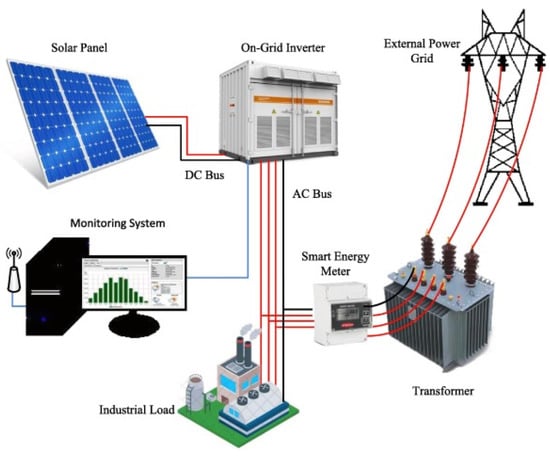
Figure 1.
PV plant schematic diagram [8].
The actual conversion efficiency of a PV power system is not same as under standard test conditions due to external dynamic weather conditions [6]. Moreover, solar irradiance, tilt angle, ambient temperature, dust, and shading effects, among other factors, also have a negative impact upon the performance of PV power system [9]. Researchers have worked hard to identify several strategies for reducing the negative effects of these factors. Indeed, monitoring the performance of already installed PV power plants from a wider perspective is essential for the accurate projection of power generation from photovoltaic systems. The installed global capacity of PV plants at the end of 2021 is shown in Figure 2.
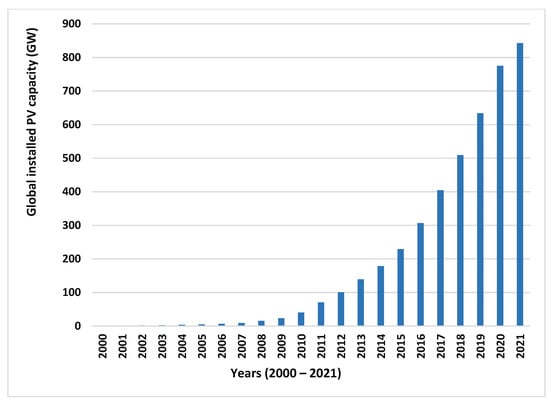
Figure 2.
Installed global capacity of PV plants [10].
In this paper, a comparative performance analysis of already installed PV power plants, in different geographical locations, is conducted in accordance with IEC standards [11]. Furthermore, various parameters that have been found to have a detrimental impact on the performance of PV power systems in previous studies are reviewed, and various strategies are investigated to improve the efficiency of these systems.
2. PV Power Plant Characteristic Parameters
The International Energy Agency (IEA) has developed several parameters to examine the performance of photovoltaic power plants [12]. These parameters define the overall performance of the plant with regard to energy generation, solar resource, and the effect of system losses, as shown in Table 1. The parameters include the performance ratio (PR), reference yield (Yr), final yield (Yf), capacity utilization factor (CUF), PV module efficiency, inverter efficiency, and system efficiency.

Table 1.
PV power performance parameters.
Table 1.
PV power performance parameters.
| Parameter | Definition | Formula | Units | Symbol | References |
|---|---|---|---|---|---|
| Reference yield | The entire in-plane irradiation, Ht, divided by the PV’s reference irradiation, G, gives the reference yield, Yr. The solar irradiance resource for photovoltaic plants is defined by the Yr. It is determined by the location, orientation of the photovoltaic array, and seasonal weather variations. | kWh/kW per day | Yr | [13] | |
| Array yield | Array Yield is the energy output of a PV array per kW of installed capacity. It is the difference between the rated PV power and the amount of energy a PV plant generates in a day or month. | kWh/kW per day | Ya | [13] | |
| Final yield | The final yield, Yf, is calculated by dividing the total output of AC energy, during a defined time interval, by the installed DC power of the solar array’s nameplate. It depicts the time required for the Photovoltaic array to operate at its rated power and produce the same quantity of energy. | kWh/kW per day | Yf | [12] | |
| Performance ratio | Performance ratio (PR) is the PV plant’s final yield divided by the reference yield. The PR is based on the plant’s overall losses during the conversion process, which are caused by various components such as cables, solar panels, and the inverter. | % | PR | [14] | |
| Capacity utilization factor | For a given time period, the capacity utilization factor (CUF) is defined as the actual output of the photovoltaic power plant divided by the theoretical output of the PV plant for the same period of time. | CUF = Eac/(Po 8760) | % | CUF | [15] |
| PV module efficiency | The module efficiency measures how much energy the solar module converts in contrast to the amount of radiation available. | % | [16] | ||
| Inverter efficiency | The inverter efficiency is calculated by dividing the AC power generated by the photovoltaic power plant by the DC power generated by the inverter. | % | [16] | ||
| System efficiency | The product of PV module efficiency and inverter efficiency gives the instantaneous PV system efficiency. | % | [10] | ||
| Array capture loss | The array capture loss is the difference between the array yield and the reference yield. A loss occurs when the actual irradiance differs from the reference or theoretical irradiance. | kWh/kW per day | La | [17] | |
| Thermal capture loss | The thermal energy losses that occur when the module temperature increases over 25 degrees Celsius are known as thermal capture losses (Lct). They are calculated using the difference between the reference and adjusted reference yields. | kWh/kW per day | Lct | [18] |
3. Comparative Performance Studies of Different PV Plants
In Table 2, a performance analysis of different PV plants is presented, which took the performance parameters, developed in accordance with IEC standards, into consideration. All PV plants in the table are installed in different geographical locations, and they have different monitoring times and durations [19]. Out of the various performance parameters, performance ratio is the key factor for measuring the performance of the PV power system. Performance ratios indicate how effectively the PV power plant is working [20]. They represent the energy losses that occur at different stages, including array capture loss, inverter loss, wiring loss, and mismatch loss [21]. The system’s components, including inverter efficiency, the cables’ characteristics, and its fixed/tracking PV mechanism, are also important factors which play significant roles in the performance of the PV power system. Depending on the rated capacity of PV plants, Table 2 is presented in descending order, from 50 MW to 1.72 kW systems. As per the results of the literature review, only 18% of PV plants showed a performance ratio less than 70%, which is quite satisfactory. In Figure 3, the graph shows the performance ratio per year. Plant observation years are displayed on the horizontal axis, whereas the average performance ratio of the plants observed in the same year is depicted on the vertical axis. Observations show that the performance ratio of the plants is increasing with each passing year [22]. This is because, as technology advances, more precise and effective systems are developed, thus resulting in a higher performance ratio.
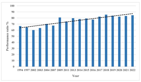
Figure 3.
Performance ratio trend with respect to time (year).

Table 2.
Performance comparison of different PV plants installed worldwide.
Table 2.
Performance comparison of different PV plants installed worldwide.
| Rref | Location | Latitude and Longitude | Rated Capacity | PV Technology | Tilt Angle | Energy Generation kWh/Year | Array Yield | Reference Yield | Final Yield | PR% | CF % | ηsyst | Monitoring Year /Duration |
|---|---|---|---|---|---|---|---|---|---|---|---|---|---|
| [23] | India | and | 50 MW | Poly-crystalline | 10° | 107,326,400 | 77.9% | 24 | 2019/1 year | ||||
| [24] | Algeria | and | 23.92 MW | Poly-crystalline | 15° | 43,261,400 | 5.46 | 4.95 | 82.0 | 20.64 | 2017–2020/3 years | ||
| [25] | Malaysia | and | 20 MW | Mono-crystalline | 26,304,000 | 4.19 | 76.8 | 15.22 | 11.54 | 2020/1 year | |||
| [26] | Mauritania | and | 15 MW | a-si, μa-si | 10° | 4.39 | 4.27 | 67.9 | 19.59 | 2015/1 year | |||
| [27] | India | and | 12 MW | Poly-crystalline | 10° | 17,611,330 | 5.5 | 4.07 | 86.5 | 20.12 | 2016/1 year | ||
| [28] | India | and | 10 MW | Poly-crystalline | 33.75°, 3.75°, 18.75°Seasonal Tilt | 15,798,192 | 4.44 | 3.33 | 85 | 17.68 | 10.12 | 2015/1 year | |
| [29] | Germany | and | 5 MW | 680 | 1.9 | 66.5 | 1994/4 year | ||||||
| [8] | Pakistan | 2.5 MW | Mono perc | 4,015,200 | 4.63 | 4.49 | 80.5 | 19.03 | 13.8 | ||||
| [30] | Ghana | and | 2.5 MW | Poly-crystalline | 12.5° | 3,547,800 | 70.6 | 16.2 | 2013–2016/3 years | ||||
| [2] | Pakistan | and | 1 MW | Poly-crystalline | 1,415,664 | 3.9 | 76.5 | 16.17 | 12.53 | 2020/1 year | |||
| [31] | Morocco | and | 1 MW | Poly-crystalline | 32° | 1,095,672 | 3.0 | 77.3 | 2020/1 year | ||||
| [32] | Italy | and | 960 kW | Mono-crystalline | 15°, 3° | 1,321,924 | 3.9 | 4.5 | 3.8 | 84.4 | 15.6 | 14.9 | 2012–2015/43 months |
| [33] | Malawi | 830 kW | HIT technology | 30° | 79.5 | 17.7 | 14.6 | 2013–2017/4 years | |||||
| [34] | Italy (PV2) | and | 606 kW | Mono-crystalline | 15° | 4 | 2012/8 months | ||||||
| [35] | Thailand | and | 500 kW | m-silicon | 15° | 1695.9 | 2.9 | 70 | 9–12 | 2004/8 months | |||
| [11] | Spain | 370 kW | Poly-crystalline | 30° | 5.46 | 4.42 | 81 | 18.45 | 10–12 | 2013–2016/3 years | |||
| [34] | Italy (PV1) | and | 353.3 kW | Mono-crystalline | 3 | 3.5–7.9 | 2012/8 months | ||||||
| [36] | Brazil | and | 336.96 kW | Poly-crystalline | 140,630 | 83.5 | 2019/4 months | ||||||
| [37] | Lesotho | and | 281 kW | Poly-crystalline | 30° | 4.75 | 6.2 | 4.17 | 67 | 17.20 | 9.58 | 2014/8 months | |
| [38] | Dubai | and | 200 kW | Mono-crystalline | 25° | 352,600 | 4.82 | 81.7 | 2019/1 year | ||||
| [39] | India | and | 190 kW | Poly-crystalline | 25° | 812.76 | 2.23 | 74 | 8.3 | 2011/1 year | |||
| [40] | Greece | and | 171.36 kW | m-silicon | 30° | 1336.4 | 1.96 | 67.36 | 15.26 | 2007/1 year | |||
| [41] | Singapore | and | 142.5 kW | Poly- crystalline | 3.8°,6.84° | 101,895 | 3.86 | 3.12 | 81 | 11.2 | 2011/18 months | ||
| [42] | Portugal | and | 124.2 kW | a-Si | 34° | 1261 | 78 | 2013/3 years | |||||
| [43] | Vietnam | and | 56.7 kW | Mono-crystalline | 18° | 68,625 | 4.0 | 3.32 | 82.4 | 14.45 | 2019/1 year | ||
| [44] | Spain | and | 40 kW | Poly-crystalline | 1.83 | 3.26 | 1.60 | 49 | 4.96 | 2003/1 year | |||
| [45] | Algeria | and | 28 kW | Mono-crystalline | 27° | 45,119 | 4.5 | 6.2 | 4.4 | 71.89 | 18.58 | 10.99 | 2017–2018/1 year |
| [46] | Oman | and | 20.4 kW | 23,595 | 3.78 | 5.59 | 3.64 | 67 | 15 | 10.3 | 2014–2018/4 years | ||
| [47] | New Zealand | and | 10 kW | m-si | 41 | 1616 | 3.87 | 2.99 | 78 | 11.96 | 2014/1 year | ||
| [48] | Hungary | and | 9.6 kW | Poly-crystalline,a-si | 30° | 8839 | 3.07 | 77.22 | 9.8 | 2016/1 year | |||
| [49] | China | and | 9 kW | Multi-junction | Dual axis solar tracker used | 3.1 | 79.8 | 18.9 | 2015/1 year | ||||
| [50] | India | and | 6.4 kW | Mono-crystalline | 1528.125 | 85.3 | 2018/1 year | ||||||
| [10] | Morocco | and | 5 kW | Poly-crystalline | 32° | 6411.300 | 4.45 | 79 | 14.83 | 11.99 | 2015/1 year | ||
| [51] | China | and | 3 kW | Poly-crystalline | 25° | 1063.04 | 3.01 | 3.62 | 2.86 | 80.6 | 10.73 | 2009/3 years | |
| [52] | South Africa | and | 3.2 kW | Poly-crystalline | 34° | 5757 | 5.8 | 4.9 | 84.3 | 20.41 | 2013/1 year | ||
| [53] | Korea | and | 3 kW | Mono-crystalline | 18° | 1007 | 63.3 | 11.5 | 7.9 | 2003/1 year | |||
| [54] | Morocco | and | 2.4 kW | Mono, poly, a-si | 30° | 3696 | 4.96 | 83.8 | 2016/4 years | ||||
| [55] | Morocco | and | 2.04 kW | Mono-crystalline | 30° | 3370.89 | 76.7 | 18.86 | 11.7 | 2015–2016/2 years | |||
| [56] | Morocco | 2.4 kW | Mono, poly, a-si | 32° | 3245.83 | 4.34 | 76.7 | 18.16 | 11.67 | 2018/4 years | |||
| [57] | Turkey | and | 2.35 kW | Mono, Poly, a-si | 30° | 3364.46 | 91 | 13.26 | 2014/1 year | ||||
| [58] | Serbia | and | 2 kW | Mono-crystalline | 1161.704 | 3.81 | 93.6 | 12.88 | 10.07 | 2013/1 year | |||
| [59] | India | and | 2 kW | Poly- crystalline | 20° | 2962 | 70 | 2019/1 year | |||||
| [60] | Spain | and | 2 kW | 9° | 1424 | 64.5 | 7.11 | 1197/1 year | |||||
| [12] | Ireland | and | 1.72 kW | Mono-crystalline | 53° | 885.1 | 2.64 | 2.85 | 2.4 | 81.5 | 10.1 | 12.6 | 2009/1 year |
4. Different Factors Affecting PV Power System Performance
A photovoltaic system’s output power and lifespan are determined by a number of factors. The type of PV technology used, the amount of solar radiation received, ambience of the temperature, cell temperature, shading effect, dust accumulation, module orientation, weather conditions, and geographical location, are some of the major factors [61]. Figure 4 shows the different factors which effect PV efficiency. This paper examines these important factors which affect PV system performance.
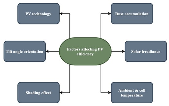
Figure 4.
Factors affecting PV system efficiency.
4.1. PV Technology
Several PV technologies are available on the market, and they are frequently used to generate electricity. These include crystalline silicon (i.e., monocrystalline and polycrystalline) and other thin film technologies, including amorphous silicon, CdTe, CIS, and CIGS. Each technology is suitable for different geographical locations [62]. Figure 5 and Table 3 show the latest technologies that have a high performance efficiency, as well as their specifications. In the literature, a number of studies compare the performance of PV technologies [48]. In Morocco, authors have compared three different types of PV technology (i.e., (m-si, p-si,a-si)), and they concluded that monocrystalline silicon technologies (m-si) have the best performance in terms of energy production and performance ratio (77%); however, they also note that polycrystalline technology is the most cost effective technology compared with others [54].
In Brazil, in different climatic conditions, six different technologies (m-si,p-si,CdTe, CIGS, A-si, μc-si) were compared. The thin film technologies (i.e., a-si) have the best PR, reaching up to 90%, although they have the lowest temperature coefficient, whereas the crystalline technologies (m-si, p-si) have the highest temperature coefficient [63]. In Abu Dhabi, four rooftop PV systems, which used monocrystalline and polycrystalline technologies, were evaluated. The analysis of the study showed that monocrystalline technologies perform better than polycrystalline technologies [64]. Figure 6, Figure 7 and Figure 8 show performance comparison graphs of different PV technologies. Figure 7 and Figure 8 display performance comparison graphs for various PV technologies. The I-V and P-V parameters for monocrystalline silicon and polycrystalline silicon PV technologies are represented graphically in Figure 7 and the impacts of the climate on various PV technologies are shown in Figure 8; therefore, these two figures provide a graphical representation of the efficiency traits of various PV technologies. Table 4 includes a summary of the literature that concerns the performances of different PV technologies. We conclude that thin film technology is more suitable in higher temperature zones than crystalline technology, which is less suitable in these regions, as it is more efficient, and it shows better results. In regions which cultivate moderate or low temperatures, crystalline technologies operate more effectively.
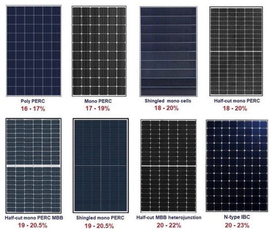
Figure 5.
Different, new PV technologies which are available on the market [65].

Table 3.
PV technologies which are highly efficient [66].
Table 3.
PV technologies which are highly efficient [66].
| Type of PV Technology | Performance Efficiency (%) | Specifications |
|---|---|---|
| Poly perc | 16–17 | Comprises multiple silicon crystal cells. On the rear of a cell, a passivation layer is added to increase efficiency. |
| Mono perc | 17–19 | Consists of a single crystal silicon cell along with Passivated Emitter and Rear Cell technology. |
| Shingled mono cells | 18–20 | Module cells are cut into five or six strips and connected with an electrically conductive adhesive for conduction. |
| Half cut mono perc | 18–20 | A typical module consists of 60 or 72 full cells. Each cell is cut in half and converted into 120 or 144 half cells. It reduces resistance and enhances efficiency by using perc technology. |
| Half-cut mono perc MBB | 19–20.5 | MBB denotes that a solar cell has 12 or 16 busbars rather than 4, 5, or 6. This indicates that the modules have a higher power output and are more reliable. |
| Shingled mono perc | 19–20.5 | Along with perc technology, conduction is achieved by cutting module cells into five or six strips and connecting them with electrically conductive adhesive. |
| Half-cut MBB heterojunction | 20–22 | Along with a multi-busbar, a HJT is a high-power hybrid cell that combines the finest qualities of crystalline silicon with those of an amorphous silicon thin film to improve efficiency. |
| N-type IBC | 20–23 | A thin p-type silicon (doped with boron) layer is layered over a much thicker n-type silicon layer in an N-type solar cell. IBC solar cells, or “interdigitated back contact” solar cells, provide greater efficiency, energy yields, and reliability. The cell is held together by a thick layer of tin-plated copper on the back. |
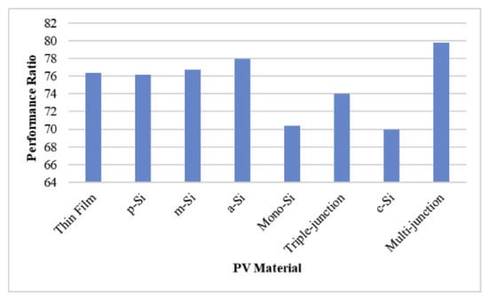
Figure 6.
Performance ratio vs. different PV technologies [67].
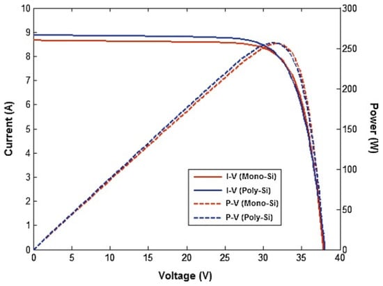
Figure 7.
Comparison between Poly-Si and Mono-Si characteristic curves [68].
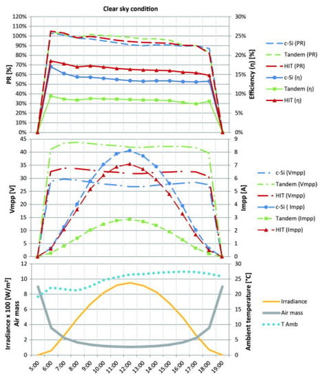
Figure 8.
Hourly parameter variation and climatic data from a clear summer day [69].

Table 4.
Summary of the literature studied, and the effect of different PV technologies.
Table 4.
Summary of the literature studied, and the effect of different PV technologies.
| Location | PV Technology | Performance Ratio (%) | Capacity Utilization Factor (%) | References |
|---|---|---|---|---|
| KNUST, Ghana | Mono-Si Poly-Si a-Si HIT | 67.9 76.3 75.8 74.8 | 11.47 12.9 12.8 12.6 | [70] |
| Meknes, Morocco | Poly-Si Mono-Si | 81.7 79.6 | [68] | |
| NMMU South Africa | Poly-Si | 84.3 | [52] | |
| UENR Nsoatre Campus, Ghana | Mono-Si Poly-Si CdTe | 75.5 75.7 77.4 | 15.37 15.41 15.75 | [15] |
| Malaysia | Mono-Si HIT a-Si | 77.85 81.25 83.37 | [71] |
4.2. Solar Irradiance
Solar irradiance from the sun has a direct relation to the energy generation of a PV system. The more solar radiation absorbed by the PV modules, the more energy that is produced from the PV system [72]. Different studies have shown that the solar irradiance and power output have a direct relationship [73]. To generate more power, the PV modules should be directly facing the sun. According to some studies, each degree of deviation from the south results in a 0.08 percent loss, specifically in the azimuth direction [74]. The electrical power output from the PV panel increases as the solar irradiation increases [75]. The module current and solar irradiance have a nearly linear relationship, as the module current increases as the solar irradiance increases [75]. In Cyprus, a study was carried out on 14 grid-connected PV systems, which took different levels of solar irradiance into consideration. We conclude that solar irradiance has a significant and direct impact on the power quality behavior of the PV system [76].
A study analyzes the effect of different outdoor parameters, including solar irradiance, on power output. The regression analysis showed that the solar irradiance has a coefficient of determination of 96.5%, thus indicating that it is the most dominant factor [77]. Figure 9 shows different levels of irradiation according to geographical location. Figure 10 shows the effect of irradiation on the performance of the PV system. As a function of yearly irradiance on the module plane, the performance ratios for monocrystalline cells were calculated in the years 1994, 1997, and 2010, as shown in Figure 11. When compared with the yearly irradiance, monocrystalline cells have the lowest performance ratio in 1994, and the highest in 2010. As a result, according to the literature, the influence of solar irradiance on PV panel performance cannot be characterized by a specific percentage increase because the relationship between the module current and irradiance value is approximately linear.
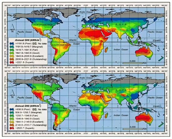
Figure 9.
Global spatial representation of global horizontal irradiation (GHI) and direct normal irradiation (DNI) [78].
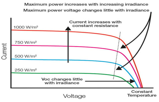
Figure 10.
Effect of irradiance on PV system performance [79].

Figure 11.
Performance ratio as a function of annual irradiance [80].
4.3. Ambient and Cell Temperature
Due to the incomplete utilization of solar irradiance by the PV power system, the remaining amount of solar irradiance is converted into heat, which causes the PV modules to overheat. Ambient temperature is one environmental factor that negatively affects the PV system’s ability to produce power [81]. As the ambient temperature increases, the module’s surface temperature also increases. Consequently, the cell temperature of the PV module also increases, which causes the operating voltage of the cell to decrease, and the power output of PV system to reduce [82]. The literature examining the impact of temperature on the efficiency of PV systems is summarized in Table 5. The table depicts the correlation between the efficiency of solar cells with respect to different temperatures. According to studies, PV cells lose 0.5% of their efficiency and have a 2.2 mV voltage loss for every 1 °C increase in operational temperature [83]. For monocrystalline PV panels, the typical power temperature coefficients range from 0.38 percent to 0.45 percent/°C, meaning that 0.38 percent to 0.45 percent of power is lost for every 1 °C increase in temperature [84]. In Figure 12 and Figure 13, different graphs are shown which represent the effect of ambient temperatures and cell temperature on the performance of a PV system. As a result, we conclude that there is no specific range of power losses that is due to PV module temperature increases.
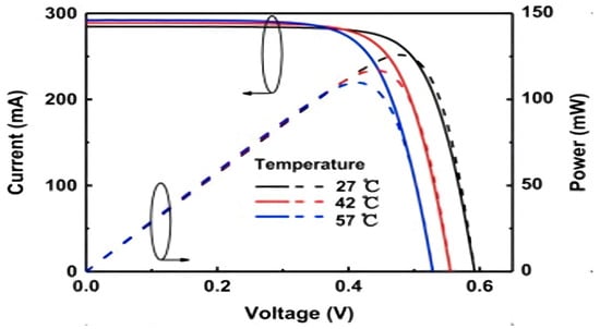
Figure 12.
I-V and P-V characteristics of solar cells under a constant irradiance of 1000 W/m2 at different temperatures [85].
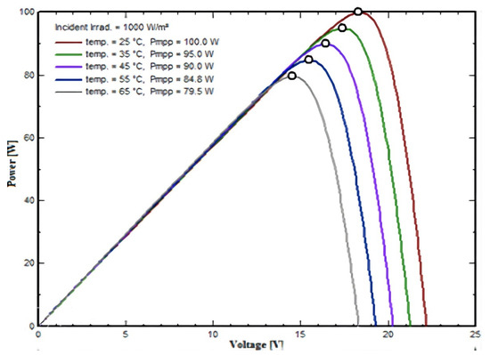
Figure 13.
A PV panel’s P-V curve characteristics under a constant solar irradiance of 1000 Wm−2 at different temperatures [86].

Table 5.
Summary of the literature that concerns the effect of temperature on PV performance.
Table 5.
Summary of the literature that concerns the effect of temperature on PV performance.
| Correlation | Comments | References |
|---|---|---|
| η = ηT_ref [1 − βref (Tc − Tref) + γlog10 I(t)] | η = instantaneous efficiency, βref = 0.0044 °C −1 | [87] |
| η = ηref [1 − a1(Tc − Tref) + a2 ln(4I(t)/1000)] | For Si a1 = 0.005 a2 = 0.052, ignoring term ‘ln’ slightly overestimates | [88] |
| η(I(t),Tc) = η((I(t),25°C)[1 + C3(Tc − 25)] | C3 = loss per °C –0.5% | [89] |
| η = ηT_ref [1 − βref (Ta − Tref) − (βref τα I(t)/UL) ] | Low predictions 5%, βref = 0.004 °C, ηT_ref = 0.15, Tref = 0 °C | [90] |
| ηi = ηT_ref [1 − βref (Tc,i − Tref) + γlog10 Ii)] | ηi = hourly efficiency, Ii = hourly incident insoltaion, βref = 0.0045 °C −1, γ = 0.12 | [91] |
| ηpv = ηref − μ(Tc − Tref) | μ = coefficient of cell temp. overall | [92] |
| ηi= ηT_ref [1 − βref (Tc,i − Tref)] | Tref = 25 °C, ηT_ref = 0.15, βref = 0.0041 °C−1 | [93] |
| η = ηT_ref [1 − MPTC(TNOCT − Tc)] | MPTC = Max. power temp. coefficient MPCT = loss per °C –0.5% | [94] |
| η = η° − c(T− T°) | T = mean solar cell temp., η° = efficiency at T°, C = Temp. coefficient | [95] |
| ηi = η25 + b(Tc− 25) | b, = b(I(t)), Tin °C | [96] |
| ηnom = − 0.05Tsurface + 13.75 ηmeasured = − 0.053Tback + 12.62 | Tsurfac = 1.06 Tback + 22.6; nominal vs. measured | [97] |
4.4. Tilt Angle Orientation
In order to absorb the maximum amount of solar radiation, the PV modules should be installed in such a way that solar radiation falls vertically on the module’s surface (i.e., at 90° to the module surface) [2]. Generally, the latitudinal angle of any region is considered to be the set criteria at which the modules should be installed [98]. The deviation of the tilt angle from the latitudinal angle is +15° and −15° in winter and summer, respectively [99]. In one study, the optimum tilt and azimuth angles, as well as the energy yield, were examined using the ground measurement data for solar irradiance and air temperature; these data were accurate to ±2% for 18 cities in Saudi Arabia [100]. The more deviations there are from the latitudinal angle, the less absorption there is of solar radiation, which reduces the ability of the PV module to generate power. Table 6 shows a summary of the literature that concerns the effect of the tilt angle on the performance of the PV system. Figure 14 shows the experimental setups that are installed at different tilt angles. One study found the optimal tilt angle by optimizing solar radiation using MATLAB [101]. The results demonstrate that 99.5 percent of solar radiation is captured when the tilt angles are adjusted six times annually. Figure 15, Figure 16, Figure 17 and Figure 18 show different graphs that demonstrate the effect of tilt angle orientations on the performance of the PV system. We conclude that the PV panel’s angle of inclination is location dependent, and consequently, site-specific.
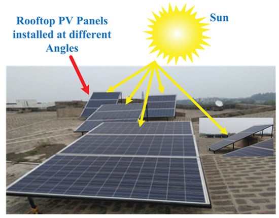
Figure 14.
Solar panels installed at different tilt angles [102].
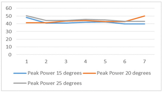
Figure 15.
Peak power (watt) with time (day index) for the three PV panels [103].
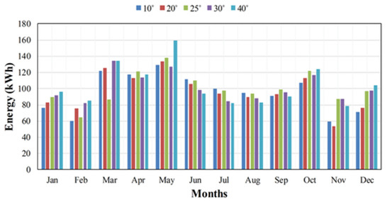
Figure 16.
Output power of PV panels, at different tilt angles, on a monthly basis [102].

Figure 17.
Monthly specific yield for all PV installations during an eight-month period [104].
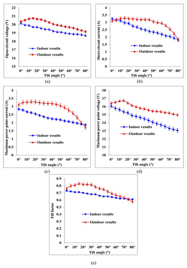
Figure 18.
Electrical parameters of a PV system as a function of tilt angle at 750 W/m2. (a) Open-circuit voltage (Voc); (b) short-circuit current (Isc); (c) maximum power point current (Impp); (d) maximum power point voltage (Vmpp); and (e) fill factor (FF) [105].

Table 6.
Summary of the literature that concerns the effect of the tilt angle.
Table 6.
Summary of the literature that concerns the effect of the tilt angle.
| Location | Fixed Angle | Tilt Angle | Generated Power at Fixed Angle | Generated Power at Tilt Angle | Difference Increased (%) | References |
|---|---|---|---|---|---|---|
| Pakistan | 30° | 14° summer and 46° winter | 1416 MW | 1491 MW | 5.3% | [2] |
| Serbia | 40.6° | 21° summer and 65° winter | 1356 MW | 1450 MW | 6.9% | [106] |
| India | 30° | 10° min. 80° max. with dual axis tracking system | 159.69 MW | 211.34 MW | 32.34% | [107] |
| Turkey | 28° | Dual axis tracking with varying tilt angles | 121.73 kW | 159.2 kW | 30.78% | [108] |
4.5. Dust Accumulation
Dust is a thin layer which partially or fully blocks the sun’s rays falling on the surface of the PV module, which thus reduces the performance of the module [109]. In Figure 19, several factors that cause dust deposition on the PV module, and the correlation between these factors, are shown. The dust accumulation on photovoltaic modules depends on three dependent variables, including environment, properties of the dust, and manner in which the PV module was installed. Figure 20 shows the experimental setups of cleaned and uncleaned PV panels. The typical annual dust reduction factor is 93%; therefore, in this context, if we use a 100 watt PV panel for testing purposes, it will generate approximately 93 watts due to dust accumulation [110]. A study found that PV voltage dropped by 80% in a 73 g/m2 area deposited with cement dust [111]. Figure 21 and Figure 22 show performance graphs of PV modules before and after dust deposition. Table 7 includes a summary of the literature that concerns the effect of dust accumulation on the performance of PV systems. As a result, we conclude that dust deposition is climate-specific, and its quantity is dependent on the location, dust type, and a variety of other parameters.
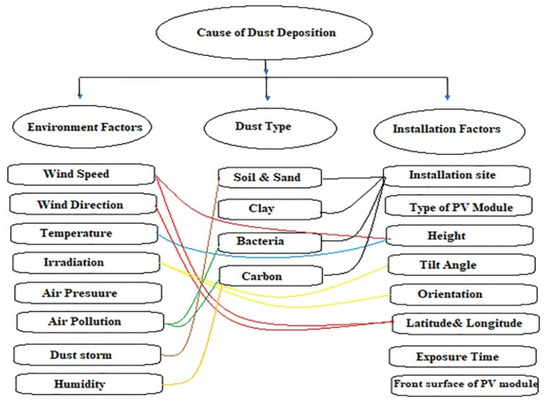
Figure 19.
Factors causing dust deposition on PV module surfaces [112].
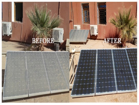
Figure 20.
PV panels before cleaning and after cleaning [113].
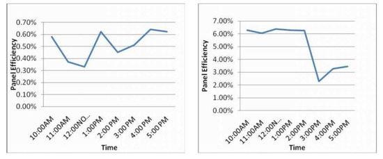
Figure 21.
PV panel efficiency with dust (Left) and without dust (Right) with respect to time characteristics [114].
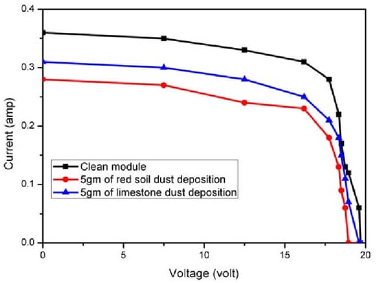
Figure 22.
PV panel I-V curve characteristics with respect to dust deposition [115].

Table 7.
Summary of the literature that concerns the impact of dust on PV systems.
Table 7.
Summary of the literature that concerns the impact of dust on PV systems.
| References | Location | Dust Composition | Methodology | Results and Tested Parameters |
|---|---|---|---|---|
| [116] | Mexico | Natural atmospheric dust | Dust impact is tested on mono, poly, and amorphous silicon PV panels. | Outdoor testing is conducted naturally. Dust properties and maximum power are examined; monthly efficiency falls to 13%. |
| [117] | Malaysia | Talcum, mud, and polyethylene | Dust impact on PV glass is tested artificially, indoors, during a one month period. | Dust weight, transmittance reduction, and dust density transmittance are examined. |
| [118] | Italy | Sandy soil | A regression model is developed for natural outdoor testing and performance is examined before and after cleaning. | Change in PV power is investigated. |
| [119] | Oman | Six outdoor dust samples | Physical and electrical parameters are taken into account when conducting indoor investigations of dust samples from six different places. | The examination of several parameters includes size, weight, loss, voltage, power, and efficiency. |
| [120] | Japan | Size distribution of the dust particle is characterized using the Microtrac S3500 | Data from a database is utilized for an energy consumption assessment. | Analysis of PV system energy consumption is performed. |
| [121] | United States | Various solar technologies exposed to dust and soiling | Outdoor investigations of physical, electrical, thermal, and chemical characteristics. | I-V characteristics, current, voltage, capacity factor, and energy yield are examined. |
| [122] | UAE | Dust samples of different sizes | Investigation and modelling of different dust particles from distinct UAE locations. | Power, voltage, PV curve, efficiency, and losses are examined. |
4.6. Shading
The effect of shadows on PV panels can reduce PV power generation [80]. Shade may be created by various structures, such as trees and poles that are built close to the PV plant site. Figure 23 illustrates various PV systems with various shadings on the PV modules. Furthermore, bird sitting, bird droppings, and leaves may fall on the panels, thus causing the shading effect to occur. As the cells are coupled in a serial fashion, the current flow in the shaded cells stops, which causes the current flow in the unshaded cells to halt as well. To reduce the power losses caused by shadings, various interconnection schemes have been proposed in the literature [123]. One study showed that even though only 2% of the panel’s area was shaded, the performance of panel was reduced by 70% [124]. Another study was conducted which showed that the performance of the array can be reduced up to 80% if 5–10% area of the array is shaded [99]. A study was conducted, wherein a fixed percentage of different kinds of cells were shaded, in accordance with their characteristics, and results showed that different power losses occurred, varying from 59% to 73% [125]. Figure 24 and Figure 25 include graphs of different shading levels and their effect on the performance of a PV system. Two maximum power point (MPPs) are seen at the P-V characteristics curve depicted in Figure 25a according to the shadow movement. The result indicates that the local maximum power point (LMPP) is separated from the global maximum power point (GMPP) and that the effect of shading is increasing as seen in the P-V curves. It is a real GMPP for the shadow situation and has a maximum power of 3419 W in total cross tied (TCT), hybrid series parallel total cross tied (SP-TCT), and novel structure (NS) configurations. Other two hybrid PV array configurations, such as bridge link total cross tied (BL-TCT) and bridge link honey-comb (BL-HC), have power outputs of 3372 W and 3379 W, respectively. The shadow movements are rising diagonally in the instance of the shadow movement depicted in Figure 25b, and several LMPPs are seen. Figure 25c illustrates the many LMPPs that are detected on P-V curves as the effect of shadow movement increases. In Figure 25d, the power of the BL-TCT combination is 2199 W, which is a true GMPP, and the power of the BL-HC combination is 2191 W, which is extremely close to a true GMPP. LMPPs on P-V curves can result in incorrect tracking to GMPP as shown in Figure 25d. As a result, we conclude that quantifying losses due to shade is dependent on the percentage of shaded cells, cell material, and panel connection. Furthermore, the nature of the shadows on the panel is influenced by the height of neighboring buildings, the presence of trees, and cross-shading from other panels.
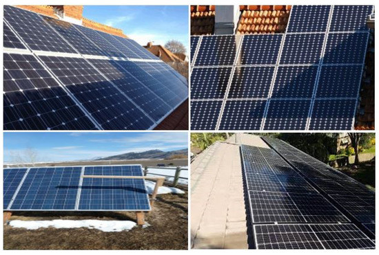
Figure 23.
Different shadows on PV panels.

Figure 24.
Measured characteristics of I-V, P-V curves for shaded and partially shaded panels [9].
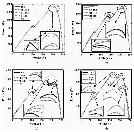
Figure 25.
Effects of various shadowing movements on P-V curves [126].
5. Different Techniques to Mitigate Performance Degradation
The collection of dust on the surface of PV panels has a significant impact on their electrical power production. Characteristics of the accumulated dust (type, size, shape, meteorology, etc.) are determined by its geographical source, and the effect of the dust not only reduces the amount of solar radiation reaching the PV surface, but it also adheres to these surfaces and scratches them, subsequently causing corrosion [125]. Moreover, cell temperature also increases due to the heat produced from unabsorbed solar radiation, and the performance efficiency decreases due to the increase in cell temperature [126]. Both factors reduce PV performance efficiency, as well as the life span of PV panels. To counter these issues, proper cleaning of PV panels, and cooling to reduce the cell temperature of PV panels, within reason, is necessary.
5.1. Cleaning Methods
The awareness of PV panel cleaning has resulted in the development of various dust accumulation mitigation techniques [127]. Figure 26 shows graphs of PV modules’ performance before and after cleaning. The cleaning of PV panels is mainly divided into two categories; the first is natural cleaning (through wind, rain, snow etc.), and the second is artificial cleaning (which is further sub-divided into manual cleaning and self-cleaning). With regard to manual cleaning, human labor is required to clean the panels. Self-cleaning is further sub-categorized into active and passive cleaning. Figure 27 depicts a flowchart that shows the different types of PV cleaning methods. This section will review all the cleaning techniques used to mitigate the negative effect of dust accumulation.
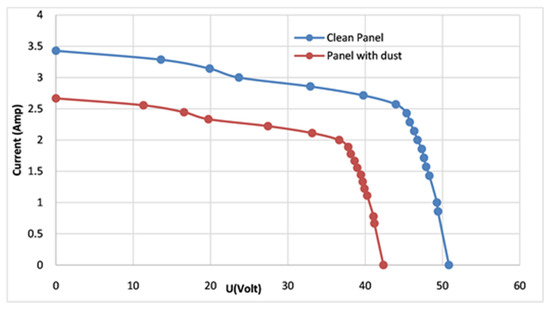
Figure 26.
Performance characteristics of a PV panel with and without cleaning [113].
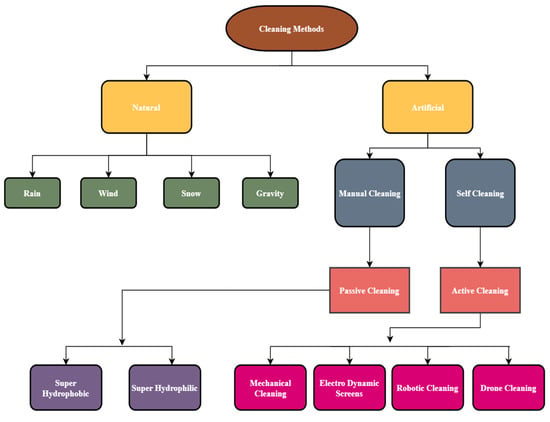
Figure 27.
Flowchart of different cleaning techniques.
5.1.1. Natural Cleaning Methods
In areas with the least air pollution, such as Europe and the United States, where dust deposition is very low, natural cleaning via wind, rain, and snow can restore the original performance of a PV system. Figure 28 shows rain cleaning PV panels. In areas with a high dust deposition rate, such as the Middle East and North Africa, which have large swathes of desert, there is a need for artificial cleaning methods to restore the original performance of a PV system. An experimental study was conducted in two European countries (Belgium and Switzerland), and it was found that rainfall recovered the performance of PV power plants; there was no need for artificial cleaning methods [128,129]. Cleaning via rainfall is an unreliable method, especially in areas with a high rate of dust deposition [130]. One study showed that the dust particles on PV modules converted into mud due to the low amount of rainfall [130]; therefore, to clean these PV modules, artificial methods are needed. Another study showed that wind can remove larger dust particles, but due to adhesive force, it cannot remove smaller dust particles (less than 50 μm) [131].
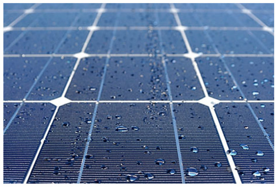
Figure 28.
A PV module being cleaned with rain [132].
5.1.2. Manual Cleaning Method
This approach requires skilled labor, water, and brushes or soft cloth of good quality. Low quality brushes can scratch the PV modules, which can reduce their efficiency. Figure 29 shows people manually cleaning PV panels. A study showed that good quality brushes must be used for cleaning PV module surfaces, otherwise, the performance and lifespan of the PV modules will be compromised [130]. This method is only suitable for PV plants with a low capacity [133]. For large-scale PV plants, pressured jets should be used, along with a brushing technique, so that efficiency can be recovered [134]. A study was conducted on water cleaning with brushing, and water cleaning without brushing, on PV modules. It was revealed that the power output increases by 6.9% when the modules were cleaned with water and brushing, and by only 1.1% when the modules were cleaned with water but without brushing [118]. This cleaning approach will be a challenge for workers due to the sensitivity of the modules, and the height at which PV modules are installed.

Figure 29.
Manual cleaning of PV panels [135].
5.1.3. Mechanical Cleaning Method
In a mechanical automated cleaning system, different controllers and sensors are used, along with brushes and a blowing system. Figure 30 and Figure 31 show schematic diagrams of mechanical cleaning setups for cleaning PV systems. This system is mainly suitable in areas where cleaning with water is impossible. Due to the complex mechanical design and the involvement of controllers, this is technique is inefficient and not cost effective; although, some studies in the literature showed prototypes and designs which perform somewhat better when using this system. In one study, a mechanical device was designed so that it used injected water, along with a brushing system, to clean PV panels automatically. The system showed that the power output increased by 15% when using this cleaning mechanism [136]. A study conducted on a single axis mechanism with solar tracking and self-cleaning, in which the PV module was cleaned two times a day, showed that the amount of power generated further increased due to the tracking system. This self-cleaning mechanism included a microcontroller, along with a gearbox and stepper motor. The limitation of this system is the highly complex mechanical design and the cost [137]. In an experimental study, two structures were designed, which effectively reduced the dust deposition factor. One structure comprises a movement sensor and a dark-activated sensor, which are controlled by the PLC, and an alarm, for indication purposes. The second structure included a PIC controller, roller brush, and different alarms [138].
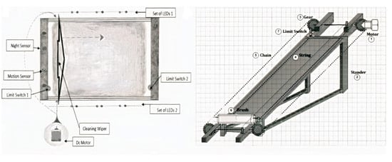
Figure 30.
Schematic diagram of an electro-mechanical cleaning system [138].
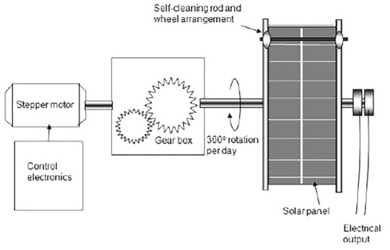
Figure 31.
Mechanical cleaning with a solar tracking system [137].
5.1.4. Electro-Dynamic Display Cleaning Method
In this method, dry dust deposits are removed automatically from PV modules without using water or any other liquid [139]. A typical schematic diagram and prototype are shown in Figure 32, Figure 33 and Figure 34 below. This cleaning method requires a high voltage supply on a screen to generate electricity, which helps the dust particles charge and move over the edge of module surface. This system can remove 90% of the dry dust deposits within the first 2 min of operation [140]. The advantages of this approach are fast speed of operation; it is independent from the complex controller system; and it has a simple controller and sensors. The disadvantages of this system are high initial costs; it is unable to remove wet dust deposits as mud particles stick to the module’s surface; and it requires a high voltage supply which reduces its efficiency by up to 15% [141].

Figure 32.
Working concept of EDS [142].
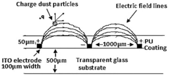
Figure 33.
EDS Schematic diagram [143].
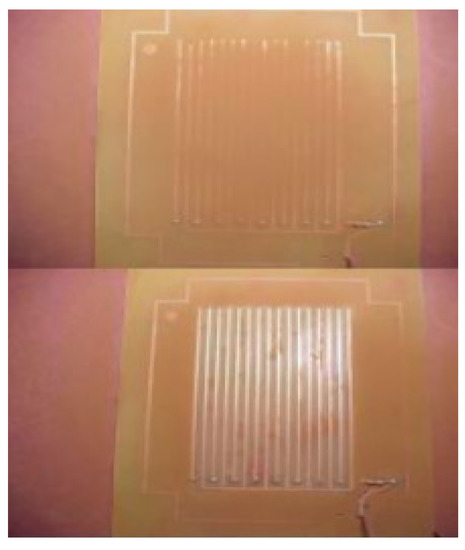
Figure 34.
EDS before (up) and after (down) voltage is applied [140].
5.1.5. Super-Hydrophobic Cleaning Method
The super hydrophobic cleaning method is presented in Figure 35. This method involves using a porous surface on the outer layer of the module. To prevent water from sticking to the PV surface, this technology coats it with a hydrophobic coating and a thin barrier layer; when tilting the PV surface at an angle, water droplets roll from the surface in the same manner that a ball rolls on a slide. Rainwater or cleaning water accumulates in low regions on the PV surface, then it quickly evaporates, leaving behind dirt that was dissolved, to later be removed [144]. It is still necessary to confirm that this method can be used in dynamic environmental and weather conditions [145]. According to a study, PV surfaces treated in this way tend to prevent dust accumulation most of the time. Highly precise structures, or nanostructures, were used to develop this approach [146].

Figure 35.
Super hydrophobic coating [147].
5.1.6. Super-Hydrophilic Cleaning Method
A super hydrophilic surface refers to a surface that has a great attraction to water. When the contact angle is close to 0°, a super-hydrophilic surface can be achieved [148]. This can be accomplished by coating the nanostructure glass surface with a titanium oxide nano-film. With this method, water droplets on the super-hydrophilic surface are flattened and widely dispersed, carrying dust particles away. The difference between super hydrophobic and super hydrophilic surfaces, as shown in Figure 36, is that water droplets on the hydrophilic surface are flattened and widely spread, but water droplets on the hydrophobic surface are mostly circular, and do not spread, as illustrated in Figure 37 and Figure 38. A study claimed that the super-hydrophilic surface is not suited for solar PV modules in arid climates since it requires rain to clean itself; therefore, this cleaning approach may be appropriate in areas with moderate to high rainfall [149]. A study found that when using a nanostructure of super hydrophilic glass, without synthetic treatment, the module became 1.23 percent more efficient than the super hydrophobic surface—only 1.39 percent of efficiency was lost [150].
The effect of a hybrid hydrophobic and hydrophilic coating on the surface of a PV module has been explored. According to the literature, this hybrid coating has outstanding anti-reflective and anti-soiling capabilities. When a PV module’s surface is coated with a hybrid hydrophobic and hydrophilic coating, water collection rates rise by 95% compared with an uncoated glass surface, and 51% compared with evenly coated, hydrophobic, low-iron glass [151].
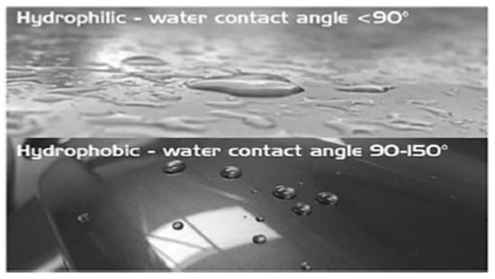
Figure 36.
Water droplets on the hydrophilic surface versus the hydrophobic surface [152].
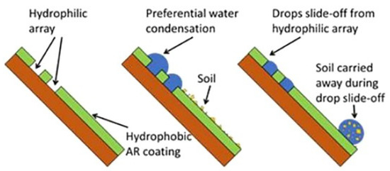
Figure 37.
Hybrid hydrophobic–hydrophilic schematic diagram [153].
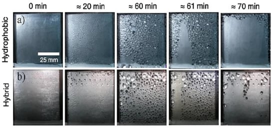
Figure 38.
Condensation of water over time on (a) hydrophobic and (b) hybrid hydrophobic–hydrophilic surfaces [151].
5.1.7. Drone-Based Cleaning Method
Drones are emerging as a viable tool for the solar panel business. They hold a number of benefits, including the fact that they encompass a broad range of surveillance technologies, they can inspect, they have an efficient data logging capacity, and they possess the ability to work at long ranges [154]. Drones for PV cleaning and monitoring applications have been presented in recent studies as a way to reduce the amount of human labor involved in the cleaning process [155,156]. Figure 39 shows PV panels being cleaned with drone technology. In a recent study, using an infrared measurement aerial system, PV modules were monitored to find anomalies in PV panels in a solar power plant [157]. Drone technology has advanced quickly in recent years, prompting experts to explore new research avenues in this area. Drones can revolutionize the way solar modules are cleaned, just as they have done recently in other fields. One study concerning drone retrofitting found that the brush and microfiber based-cloth wiper are best-suited for drone-based solar panel cleaning due to their low weight, small size, and ease of usage [158]. Some companies offer commercial products for cleaning solar panels, which include drones, and such drones have inbuilt glass cleaning equipment, as well as a removable cleaning solution container. These companies also intend to utilize drones for cleaning mirrors using concentrated solar energy [159].
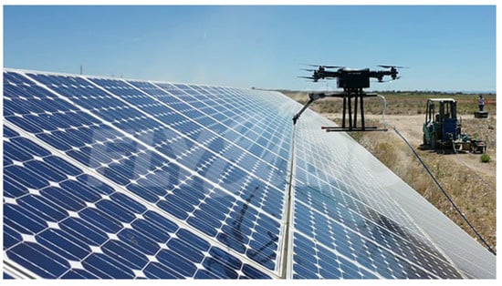
Figure 39.
Drone-based PV cleaning [160].
5.1.8. Ultrasonic Self-Cleaning Method
This method is used to remove pollutants from water-based media. Dirt, oil, grease, polishing compounds, and mold-releasing agents are some of the pollutants that can be found in the environment. Metals, glass, ceramics, and other materials can all be cleaned by using this technique. Due to the small size of the comparatively large droplets, ultrasonic cleaning may efficiently reach small cracks and remove very fine dust particles. The resonance frequency of the transducer is determined by the size of the bubbles and the size of the spray, which ranges from 20 to 80 kHz in ultrasonic transducers used in the cleaning sector. Figure 40 shows PV panels before and after being cleaned via ultrasonic cleaning. A study was conducted on the use of ultrasonic cleaning as a cleaning method, and it discovered that surface immersion in an independent bath was the best way to obtain a positive outcome. Experiments have demonstrated that cleaning PV surfaces requires a thin liquid layer (less than 1 mm) to produce the cavities required for the surface cleaning process to be completed [161].
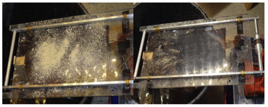
Figure 40.
Uncleaned (left) panel and cleaned (right) PV panel after ultrasonic cleaning [161].
5.1.9. Robot Cleaning Method
The design and development of a robotic cleaner for cleaning PV modules at the Quaid-e-Azam Solar Park was reported in a study (QASP) [162]. To provide a slippage-free motion and cleaning on a glassy surface, the mechanism principally consists of a ducted fan, a roller brush, and blower fan. A series of field trials and experiments have shown that the method is effective in cleaning the modules [162]. According to a study, robotic cleaning raises installation and maintenance costs while lowering water consumption. They conducted the experiment using two monocrystalline PV modules that were identical. The cleaning system on one PV module comprises an electrical motor and a brush that uses a spray, whereas the cleaning system on the other PV module does not require any other mechanism [163]. When compared with a PV module that was not cleaned, the PV module that was treated with the cleaning system generated more power; however, the cleaning system’s operating costs were higher throughout the same test period. In 2017, a robot was designed, introduced, and tested, in order to clean a 1 MW solar power plant in a study, as shown in Figure 41. The generated power was collected on a daily basis and compared with the generated power obtained from panels that were not cleaned during the same period. The findings revealed that the cleaning technique was successful in reducing the impact of dust on the solar panel’s power output. As a result, power generation increased by 32.27 percent on average [162]. In Figure 42, a portable robotic cleaning system, with a versatile platform that travels the length of a panel, is shown. The robot’s control system was implemented using an Arduino microcontroller. The robot’s initial testing phase yielded positive results, thus indicating that such a system is feasible. Future design enhancements have been considered, particularly regarding the various means that are available to transfer the robot from one panel to the next. Finally, it was discovered that robotic cleaning solutions are practical and can aid in the efficient maintenance of clean PV panels [162]. Table 8 includes a summary of the literature which examines different cleaning methods for PV systems.
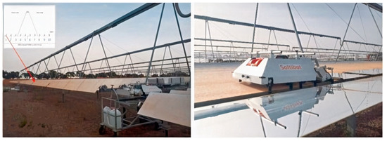
Figure 41.
Dirty PV array (left) and robotic cleaning (right) [164].
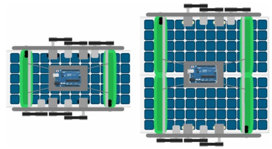
Figure 42.
Prototype of a robotic cooling system for PV panels [165].

Table 8.
Summary of the different cleaning methods noted in the literature for PV systems.
Table 8.
Summary of the different cleaning methods noted in the literature for PV systems.
| References | Cleaning Method | Advantages | Disadvantages | Max. Efficiency |
|---|---|---|---|---|
| [131] | Natural cleaning | No resources required No cost required | Ineffective for small dust particles and is weather dependent | |
| [166] | Manual Cleaning | No electricity required and environmentally friendly | Costly, needs water, and human intervention needed Scratches may be produced | 99% |
| [138] | Mechanical Cleaning | Cleaning and scrubbing the PV Automatic activation whenever required | Electricity required Maintenance cost is high | 95% |
| [167] | Electrodynamic screens | No need of any mechanical or moving parts Fast and effective | Cost is high Less effective for smaller particles High voltage and digital signals required PLC microcontroller is required | 90% |
| [165] | Robotic Cleaning | Low power consumption and rechargeable Automatic cleaning | Cost is high Filters need to be changed periodically | |
| [168] | Super-hydrophobic Cleaning | No need of electricity | Optical performance reduced | 71.8% |
| [150] | Super-hydrophilic Cleaning | Further enhances natural cleaning | Limited lifetime Ineffective in the long term | 70% |
| [169] | Ultrasonic Cleaning | No water required No human intervention needed | High levels of humidity make it less effective | 75% to 99% |
| [155] | Drone-based Cleaning | Automatically functions Highly effective | High cost |
5.2. Cooling Methods for PV Systems
External climate variables such as sunlight, wind speed, moisture, atmospheric temperature, and concentrated dust all influence the changes in surface temperature. As it is more difficult to change the other parameters involved, increasing efficiency can be achieved by lowering the operating temperature. Figure 43 shows the efficiency of solar cells with respect to temperature. Solar radiation is an unpredictable parameter; for example, this is especially the case when photovoltaic panels are installed on building façades, which are vertical and non-directional surfaces. A variety of cooling strategies have been tested and discussed in the literature to make photovoltaics more efficient by minimizing the issue of temperature increases. Figure 44 shows a flow chart of different cooling techniques for PV systems.
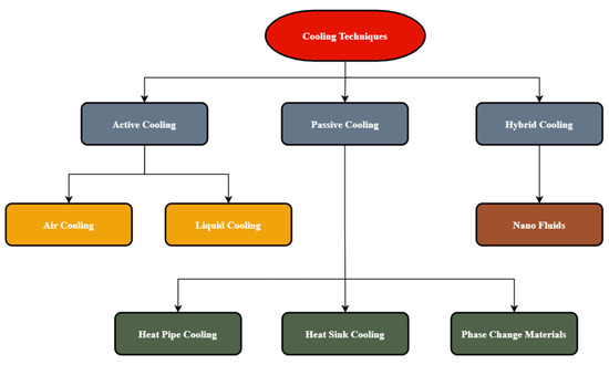
Figure 44.
Flowchart diagram of cooling techniques.
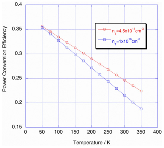
Figure 43.
Efficiency of solar cells vs. temperature, with trap densities [170].
5.2.1. Air Cooling
Fans, or other techniques which create airflows, are used in active air-cooling systems. Waste heat generated by solar panels can be utilized in these systems. As a result, if metallic materials with fins are mounted on the back surface of photovoltaic panels, in order to provide more air circulation, the cooling of the panels can be significantly improved [171]. By creating an air gap between the walls and the photovoltaic system, the temperature of the photovoltaic system can be kept below 40 °C. Open-air channels, metal frames, fins, and ducts beneath solar panels are examples of forced airflow solutions. Array ducts were used in a study to significantly lower the temperature of solar panels and boost their efficiency by 12% to 14% [172]. For the purposes of thermal management and temperature reduction, air cooling systems are commonly used in a variety of devices. Although air cooling is not as efficient as liquid cooling, it does have some advantages, such as little material usage and cheap running costs. The air is circulated using a mechanical device, such as a pump, with this form of heat control [173]. The results of a study using forced air cooling to increase the performance of a PV module were compared with PV modules that did not have any cooling system. According to the comparison, adopting an air-cooling approach resulted in greater electric efficiency and a better power ratio by 7.2 percent and 6 percent, respectively [174]. Air precooling can considerably increase the effectiveness of PV thermal management due to the high ambient temperatures in specific areas. According to some studies, this difficulty can be overcome by using air precooling [175]. To examine air precooling, a subterranean heat exchanger was employed in a study. Figure 45 shows a diagram of their experimental setup. In their research, different ambient air temperatures of 35, 40, and 45 degrees Celsius, as well as varying flow rates, were evaluated to see how they affected the module’s efficiency. It was discovered that by using a heat exchanger, it is possible to adjust the temperature effectively. By comparing the power output of the panels, it was evident that using this type of cooling can increase daily electrical efficiency by up to 29.11% [176].
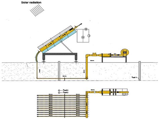
Figure 45.
Schematic diagram of an air-cooling system in a PV system [176].
5.2.2. Liquid-Based Cooling
The continuous operation of this type of cooling system requires water; indeed, these methods are challenging, and additional energy for pumping is needed. Solar-powered D.C. pumps in active cooling technologies can be used to circulate water in any of these systems. A variety of active cooling systems that use water have been investigated, and some of the more effective approaches are discussed in this section. Another effective cooling method is forced convection, which is created using a liquid flow inside the channels that are inserted into the back of PV modules [177]. Under Egyptian climate conditions, a comparison of cooling solutions for PV modules, with reflectors, was conducted. The study looked at three alternative cooling techniques: forced air, water cooling, and a combination of forced air and water cooling. The results revealed that under Egyptian climate conditions, water cooling was the optimal cooling method for PV modules [178]. Several unique ideas regarding the liquid cooling of PV modules are being investigated, with the goal of achieving a more uniform temperature in the cells; one such idea is the implementation of a converging channel, which was tested in a study [179]. The prototype design of the channel is shown in Figure 46. In terms of temperature uniformity, the 2° converging angle produced the best results. According to the system’s thermal study, the PV temperature can be reduced by employing converging channels from 71.2 °C to 45.1 °C, and from 48.3 °C to 36.4 °C, on a typical hot day in June and a typical cold day in December, respectively. Other factors, such as the type of coolant used, influence how much the temperature drops by in PV panels that use liquid cooling [180]. The contact thermal resistance at the heat sink/cell interface is the fundamental disadvantage of the abovementioned liquid cooling approaches. Direct liquid immersion is recommended as a solution to this problem [181]. With this cooling method, the cell is submerged in a circulating fluid, which is commonly utilized for cells in concentration systems due to its high convective heat transfer coefficient [182]. The Reynolds number and the inlet temperature of the circulating fluid are two of the most effective elements in terms of modifying the temperature of the cooled cell [183].
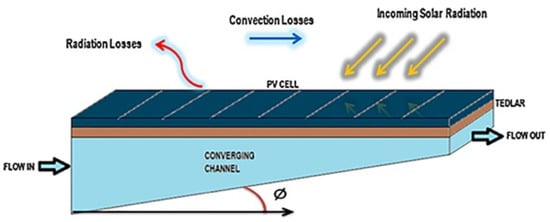
Figure 46.
Converging channel used for PV cooling [179].
5.2.3. Heat Pipe-Based Cooling
A heat pipe is made up of three parts: an evaporator, an adiabatic transfer section, and a condenser with working fluid—these comprise both the liquid and gas sections of the pipe. For greater absorption and heat transfer in solar collectors, one study used a nano-material base fluid [184]. Heat pipes are an appropriate upgrade from solid heat sinks, or in some cases, an alternative to the pumped liquid cooling system. They have a high thermal conductivity, are easy to bend and shape, and have a long life. A heat pipe is a two-sided sealed pipe, constructed of copper or aluminum, that works with water or ammonia as a working fluid. Due to its low sensitivity to tilt angles, compared with its gravity-assisted counterparts, pulsating heat pipes (PHP) are one of the most widely used forms of heat pipe [185]. Due to its unique properties, PHPs are a viable alternative to conductive fins for cooling PV modules. A single-turn PHP was used to manage the thermal behavior of a PV panel in a published study [186]. The PHP was placed at the back of the module in this study, as illustrated in Figure 47. As shown in Figure 48, heat was dispersed through radiation and convection. On monocrystalline silicon solar cells, a finite difference approach for solving the transient heat equation was used at a heat flow of 1000 W/m2 and an immediate surrounding temperature of 291 K. The numerical findings demonstrated that using PHP instead of copper, while maintaining the same size and geometry, resulted in a greater reduction of the PV modules’ temperature.
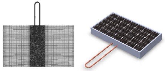
Figure 47.
Model of a PV panel with a heat pipe [186].
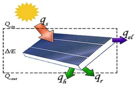
Figure 48.
Energy conservation for PV cell [186].
5.2.4. Heat Sink-Based Cooling
A heat sink is a device or material that absorbs and transfers heat from one object to another via thermal contact (either direct or radiant). Ambient air, an induced draught air column, or a coolant is used to dissipate heat [187]. Additional components for heat sinks, such as fins made from metallic materials that are mounted on the back of photovoltaic panels to enable convective heat transfer from air to panels, might improve the passive cooling of photovoltaic panels [188]. Heat sinks with a high thermal conductivity are usually placed behind the solar cell. As the cooling speed may be high, transverse ribs, V-shaped ribs, and arc-shaped rough surfaces, are utilized to improve the heat transfer coefficient [189]. The heat transfer area, which is the area that transfers heat from the solar cells to the ambient environment, is increased by using a heat sink. One study devised an approach for increasing electricity efficiency by attempting to cool the solar panels using heat sinks and a wicker-like structure made of copper and aluminum fins [190]. Due to its simplicity and low cost, it offers a great deal of potential for cooling PV panels. Figure 49 and Figure 50 show the heat sink mechanism used for cooling the PV panel. One study used aluminum fins in the shape of an ‘L’ and pasted them on the back of the PV panel with thermal conductive paste. During the analysis, it was discovered that randomly distributed fins, with holes on the back, provided optimum cooling for the PV panel, since air was able to permeate the interior section of the structure at 1 m/s [191].

Figure 50.
Model of a PV panel with a heat sink [36].
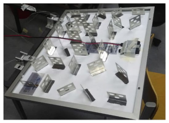
Figure 49.
Heat sinks on backside of PV panel [192].
5.2.5. Phase Change Materials-Based Cooling
Phase change materials (PCM) comprise one of the PV cooling techniques that work efficiently. PCMs are compounds that can retain thermal energy, thus allowing for temperature control. When these undergo a physical change, such as during the melting and freezing cycle, they absorb or release considerable amounts of so-called “latent” heat. Organic oil, inorganic salt hydrates, and eutectics are all mentioned as PCM [193]. A working system using PCM technology may be seen in a Japanese home that uses air to cool PV panels. The PCM installed in the building’s roof and ceilings are charged by a grid-connected 4.2 kW system, which reduces the building’s heating and cooling requirements [194]. It should also be noted that the increase in efficiency with PCM is greatest in areas with high solar radiation throughout the year. Other factors that were discovered as having a significant impact on panel efficiency include the thickness of the panels and the thermal conductivity of the PCM. The PV panels’ cooling performance with microencapsulated PCM was investigated, and it was discovered that PCM with a melting temperature of 30 °C performed better than PCM with a melting temperature of 28 °C. One study concluded that after a certain thickness, PCM could not entirely solidify at night, thus compromising its cooling capacity [195]. A PCM-based cooling setup for a PV panel was developed in a study. As illustrated in Figure 51, paraffin-based PCM, with a melting temperature of 38 °C to 43 °C, were inserted at the rear of a panel in this particular setup. When comparing the annual electricity generated by the panel, in hot climate conditions, it was discovered that employing PCM for cooling resulted in a 5.9% increase in electricity generation. Furthermore, less cooling was seen under peak hot and cold conditions, which was attributed to partial solidification and melting, respectively [196].
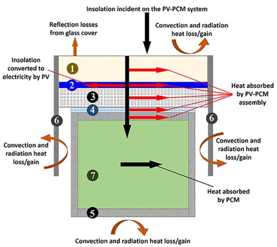
Figure 51.
Schematic of a PV-PCM system: (1) glass cover; (2) cell of the PV panel; (3) back sheet of the PV panel; (4) epoxy glue layer; (5) wall of the PCM container; (6) frame of the PV panel; and (7) layer of PCM [196].
5.2.6. Nanofluid-Based Cooling
In most nanofluid-based PV/T systems, nanofluid can be used in two ways: as a coolant and as a spectral filter. According to the literature, PV/T systems that employed nanofluid in any form, as a coolant or filter, had higher overall exergy generation and energy efficiency than PV/T systems that used conventional fluid [197]. An experimental study was conducted to explore the benefits of a PV/T system on the PV module. The study recognized the PV/T technologies’ potential in Hong Kong. The maximum electrical efficiency achieved during the experiment was 16 percent, although the authors did not investigate the thermal performance. The experiment’s setup is shown in Figure 52 [198]. To cool the PV panel and improve system performance, various nanoparticles combined with water are employed as nanofluids [199]. To improve heat transportation, different nanoparticles, with varying weight percentages, are utilized [200]. Some nanoparticles used for this purpose are aluminum oxide (Al2O3), zinc oxide (ZnO), titanium oxide (TiO2), magnetite (Fe3O4), silicon carbide (SiC), and copper oxide (CuO); these are all examples of minerals.

Figure 52.
The schematic diagram of the experimental setup [198].
5.2.7. Hybrid Cooling
A typical PV/T device comprises a PV module linked with a thermal absorber. Technically, solar collectors for hybrid PV/T can be created so that they perform with an efficiency of over 80 percent, in a cumulative capacity. In the PV/T system, the electrical and thermal outcomes cannot be considerably increased at the same time. Moreover, research into hybrid cooling systems that use the following configurations at the same time is uncommon, such as PV/T with PCM; PCM with nanofluids; a heat pipe with a heat sink; and a heat sink with PCM. The experimental setup for a hybrid cooling system is shown in Figure 53. The use of a nanofluid in a PCM system, based on PV/T, is examined and compared with the use of a traditional PV module [201]. A study employed water-based boehmite to cool photovoltaic panels with 0.01 wt%, and saw a 27 percent boost in efficiency [202]. An experimental study was conducted in which a heat exchanger, water pumps, a nanofluid container, and a data collecting system were all included in the system. A water tank was built behind the enclosure to store the thermal output. To avoid heat escaping into the environment, the PCM container was isolated from its back and sides with 2 cm of thick glass wool. This insulation caused all the heat from the PV panels to condense in the reservoir, which was subsequently drained using water and nanofluids [203]. For home and commercial applications with high electrical and thermal energy demands, technologies can provide significant financial benefits. Table 9 shows a summary of the literature which examined different cooling techniques for PV systems.
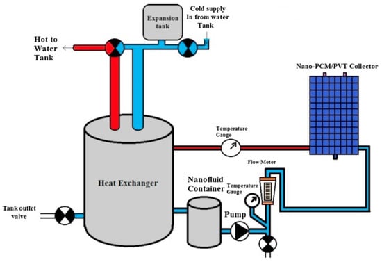
Figure 53.
Schematic diagram of an experimental setup for a hybrid cooling system [203].

Table 9.
Summary of different cooling techniques noted in the literature.
Table 9.
Summary of different cooling techniques noted in the literature.
| References | Cooling Type | Cooling Agent | Electrical Performance | Findings |
|---|---|---|---|---|
| Air Cooling [204] | Air Cooling | Air | Performance efficiency increased from 8–9% (before cooling) to 12–14% (after cooling). | Heat transfer simulation model developed and compared with experimental results. |
| [205] | Air cooling | Air | Electrical efficiency range was 12–12.4%. | By reducing the depth of the channel, the thermal efficiency range was 15–31%, with little impact on electrical efficiency or the |
| [206] | Air cooling | Air | By reducing cell temperature, the electrical efficiency was enhanced. | heat transfer rate. Performance efficiency increased by arranging fins perpendicular to air flow. |
| [173] | Air cooling | Air | Electrical efficiency increased to a satisfactory level. | Theoretical model was developed by using a thin flat metal sheet suspended in the middle of an air channel. |
| Liquid Cooling [207] | Liquid cooling | Water | Electrical efficiency increased by 9%. | A numerical model was developed which estimates electrical and thermal parameters. Using this system, the cell temperature dropped to 20%. |
| [208] | Liquid–Gas cooling | Water and air | Electrical efficiency increased to 38%. | Dual phase cooling model proposed which reduced the cell temperature by 20%. |
| [182] | Liquid cooling | De-ionized water immersion | Electrical performance was not favorable for a long period of time. | The coefficient of the convective heat transfer was approximately 6000 W/m2K. |
| Heat Pipe Cooling [209] | Heat pipe cooling | Serpentine half pipe | Electrical performance increased above 11.5%. | A mathematical model was developed and validated with experimental data. Thermal efficiency increased up to 70%. |
| [186] | Heat pipe cooling | Pulsating heat pipe single turn | Electrical efficiency of system increased to 18%. | A transient numerical simulation was performed with actual data. Cell temperature was reduced to 16.1 K. Efficiency increased very quickly. |
| [210] | Heat pipe cooling | Heat pipe with microchannel loop mechanism | Electrical efficiency of system increased from 10% to 16%. | Thermal max. efficiency was 71.67%. Condensation and evaporation improved using this system. |
| Heat Sink Cooling [211] | Heat sink cooling | Air cooled, perforated aluminium fins | Pmp and Voc increased by 18.67% and 10%, respectively. | CFD analysis performed with and without fins. Thermal efficiency increased by 14.65%. |
| [192] | Heat sink cooling | Air cooled, perforated aluminum fins | Electrical efficiency increased by 2% with use of randomly placed fins. | System was efficient for both high and low solar isolation. |
| [212] | Heat sink cooling | Air cooled, aluminum fins | Electrical efficiency increased by 2.72%. | Experimental and economic analysis presented. Thermal efficiency increased by 8.7%. |
| Phase Change Materials (PCM) [196] | PCM | PCM-RT42 | Electrical efficiency increased by 5.9%. | Comparative analysis performed for both summer and winter. Average annual temperature dropped to 10.5 °C. |
| [213] | PCM | Organic paraffin wax | Electrical efficiency increased to 5.39%. | Position of PCM influenced the efficiency. Module temperature reduced to 15 °C. |
| [214] | PCM | Heat exchanger and paraffin wax | Electrical efficiency improved to 5.18%. | Extracted heat in this system can be utilized for other purposes. Temperature was reduced to 23 °C. |
| [215] | PCM | RT28HC | Electrical efficiency improved to 4.3–8.7%. | Simulations on TRNSYS software were performed for data validation. Temperature decreased to 35° C. |
| Nano-fluid Based Cooling [180] | Nanofluid | Ag/water (10% vol.) Al2O3/water (10 vol%) | Electrical efficiency improved to 3.9% and 1.83%, respectively. | Two types of nanofluids were used. Performance of the PV/T collector was experimentally analyzed. Thermal efficiency improved to 12.43% and 4.54%, respectively. |
| [198] | Nanofluid | SiC/water (1 wt%) | Electrical efficiency improved to 13.52%. | Thermal efficiency of this system increased to 81.73%. |
| [216] | Nanofluid | Al2O3-water | Electrical efficiency increased to 50%. | Thermal efficiency for this system increased above 55%. |
| [199] | Nanofluid and Ultrasonics | Atomized CuO | Electrical performance increased to 51.1%. | Thermal efficiency improved to 57.25%. |
6. Recommendations and Future Challenges
During the last two decades, PV-based electricity generation has become increasingly popular all over the world. PV power systems have emerged as one of the main prospective power supply options. According to this literature review, the following comprise the recommendations and future challenges in this field.
- Enhancing PV technology and efficiency would be more advantageous in terms of greenhouse gas emissions per unit of electricity generated.
- By using photovoltaic power plants as a source of renewable energy-based power production, the level of greenhouse gas emissions will be reduced from what is currently being produced due to fossil-fuel-based power plants.
- Another significant factor to consider when connecting local PV power generation to the grid is power quality, as low power quality can create serious issues for most equipment and financial losses.
- There is a need to focus on hormonic distortion, power factor correction, voltage, and frequency regulation issues.
- To build artificial intelligence-based models for reducing dust accumulation, and to reduce the impact of similar issues, further studies should be conducted. The developed model will help determine the appropriate cleaning strategy based on the model pattern. In addition, hybrid cleaning methods are worth investigating to determine the optimum combination, especially with regard to making the most economical choice and for selecting the best materials.
- In order to make the cell’s working conditions more flexible, it would be beneficial to research hybrid cooling technologies that combine many alternative thermal management strategies.
- A hybrid system can use active techniques to boost efficiency during high solar irradiance and ambient temperature periods, while also depending on passive techniques for everyday operations.
7. Conclusions
This paper examines, evaluates, and synthesizes published research on photovoltaic power systems in terms of their advancements and challenges faced. The review provided an intensive look at (1) the performance assessment of PV power plants, (2) various factors affecting their performance, and (3) different methodologies adopted to mitigate these negative effects. Using the IEC standard, various PV plants from around the world were compared. According to this review, PV power plants can easily operate in most of the global locations mentioned, since different power plants have been able to supply enough electricity in terms of kWh/kW/year in nearly every region of the world. It has been shown that plant performance improves each year as PV material-based technology and inverter topologies also improve. It was also proven that a variety of factors (some of which have a positive impact on production, whereas others have a negative impact), affect the overall performance of PV systems. To mitigate the negative effect on PV systems, different cleaning and cooling techniques have been investigated, analyzed, and compared. Several variables, including PV size, design, location, water accessibility, dust type, and other attributes, were taken into consideration when determining the optimal cleaning techniques for each PV system. This comprehensive and critical review on PV power systems will be helpful for researchers, designers, and investors dealing with photovoltaic systems.
Author Contributions
Conceptualization, A.A. and N.A. (Naseer Ahmed).; methodology, A.A. and S.A.Q.; validation, N.A. (Naseer Ahmed).; formal analysis, N.A. (Naveed Ahmed) and S.A.Q.; writing—original draft preparation, A.A.; writing—review and editing, M.A. and N.A; supervision, M.A. and N.A. (Naveed Ahmed). All authors have read and agreed to the published version of the manuscript.
Funding
This research received no external funding.
Data Availability Statement
Not applicable.
Acknowledgments
We acknowledge the support of Department of Energy and Petroleum Engineering at the University of Stavanger, Norway, and the US Pakistan Centre for Advanced Studies in Energy, National University of Sciences and Technology, in publishing this paper.
Conflicts of Interest
The authors declare no conflict of interest.
Nomenclature
| PV | Photovoltaic |
| PR | Performance Ratio |
| CUF | Capacity Utilization Factor |
| YR | Reference yield |
| YF | Final Yield |
| AC | Alternative Current |
| DC | Direct Current |
| IEA | International Energy Agency |
| IEEFA | Institute for Energy Economics and Financial Analysis |
| Voc | Open circuit Voltage |
| Isc | Short circuit Current |
| CdTe m-Si a-Si CdTe CIGS HIT βref | Cadmium Telluride Multi crystalline silicon Amorphous silicon Cadmium telluride Copper indium gallium selenide Heterojunction technology Reference temperature coefficient |
| Epv | Photovoltaic Electricity Generated |
| Eac | AC Energy output |
| Tamb | Ambient Temperature |
| Ht | Total in-plane irradiance |
| G | PV’s reference irradiance |
| St | PV Modules Area |
| ηPV | Module Efficiency |
| ηinv | Inverter Efficiency |
| Hsys η | System Efficiency Instantaneous efficiency |
| η | Efficiency |
| Lc | Capture losses |
| Ls PLC PIC MPCT TNOCT Tref ηT_ref | System losses Programmable logic control Peripheral interference controller Maximum power temp. coefficient Nominal operating cell temperature Reference temperature Efficiency at reference temperature |
References
- Razi, M.; Ali, Y. Social, Environmental and Economic Impacts of Adopting Clean Energy Use. Int. J. Decis. Support Syst. Technol. 2019, 11, 29–49. [Google Scholar] [CrossRef]
- Aslam, A.; Khan, A.N.; Ahmed, N.; Ahmed, N.; Imran, K.; Mahmood, M. Effect of Fixed and Seasonal Tilt Angles on the Performance of an ON-Grid PV Plant. In Proceedings of the 2021 International Conference on Emerging Power Technologies 2021, Topi, Pakistan, 10–11 April 2021; pp. 1–5. [Google Scholar] [CrossRef]
- Sengupta, M.; Habte, A.; Wilbert, S.; Gueymard, C.; Remund, J. Best Practices Handbook for the Collection and Use of Solar Resource Data for Solar Energy Applications, 3rd ed.; National Renewable Energy Lab. (NREL): Golden, CO, USA; pp. 1–348.
- Kumar, N.M.; Subathra, M.S.P.; Moses, J.E. On-Grid Solar Photovoltaic System: Components, Design Considerations, and Case Study. In Proceedings of the 2018 4th International Conference on Electrical Energy Systems (ICEES), Chennai, India, 7–9 February 2018; pp. 616–619. [Google Scholar] [CrossRef]
- Matsumoto, Y.; Antonio Urbano, J.; Pena, R.; de La Luz Olvera, M.; Pitalua, N.; Luna, M.A.; Asomoza, R. Performance Comparisons of a PV System by Monitoring Solar Irradiance with Different Pyranometers. In Proceedings of the 2017 IEEE 44th Photovoltaic Specialist Conference (PVSC), Washington, DC, USA, 25–30 June 2017; Volume 1, pp. 632–637. [Google Scholar] [CrossRef]
- Agrawal, M.; Chhajed, P.; Chowdhury, A. Performance Analysis of Photovoltaic Module with Reflector: Optimizing Orientation with Different Tilt Scenarios. Renew. Energy 2022, 186, 10–25. [Google Scholar] [CrossRef]
- Høiaas, I.; Grujic, K.; Imenes, A.G.; Burud, I.; Olsen, E.; Belbachir, N. Inspection and Condition Monitoring of Large-Scale Photovoltaic Power Plants: A Review of Imaging Technologies. Renew. Sustain. Energy Rev. 2022, 161, 112353. [Google Scholar] [CrossRef]
- Ahmed, N.; Naveed Khan, A.; Ahmed, N.; Aslam, A.; Imran, K.; Sajid, M.B.; Waqas, A. Techno-Economic Potential Assessment of Mega Scale Grid-Connected PV Power Plant in Five Climate Zones of Pakistan. Energy Convers. Manag. 2021, 237, 114097. [Google Scholar] [CrossRef]
- Atsu, D.; Seres, I.; Aghaei, M.; Farkas, I. Analysis of Long-Term Performance and Reliability of PV Modules under Tropical Climatic Conditions in Sub-Saharan. Renew. Energy 2020, 162, 285–295. [Google Scholar] [CrossRef]
- Attari, K.; Elyaakoubi, A.; Asselman, A. Performance Analysis and Investigation of a Grid-Connected Photovoltaic Installation in Morocco. Energy Rep. 2016, 2, 261–266. [Google Scholar] [CrossRef]
- Martín-Martínez, S.; Cañas-Carretón, M.; Honrubia-Escribano, A.; Gómez-Lázaro, E. Performance Evaluation of Large Solar Photovoltaic Power Plants in Spain. Energy Convers. Manag. 2019, 183, 515–528. [Google Scholar] [CrossRef]
- Ayompe, L.M.; Duffy, A.; McCormack, S.J.; Conlon, M. Measured Performance of a 1.72 KW Rooftop Grid Connected Photovoltaic System in Ireland. Energy Convers. Manag. 2011, 52, 816–825. [Google Scholar] [CrossRef]
- Sundaram, S.; Babu, J.S.C. Performance Evaluation and Validation of 5 MWp Grid Connected Solar Photovoltaic Plant in South India. Energy Convers. Manag. 2015, 100, 429–439. [Google Scholar] [CrossRef]
- Man Bajracharya, S.; Maharjan, S. Techno Economic Analysis of Grid Tied Solar System: A Case Study of Nepal Telecom. Sundhara Kathmandu 2019, 7, 211–218. [Google Scholar]
- Obeng, M.; Gyam, S.; Sarfo, N.; Kabo-bah, A.T. Technical and Economic Feasibility of a 50 MW Grid-Connected Solar PV at UENR Nsoatre Campus. J. Clean. Prod. 2019, 247, 119159. [Google Scholar] [CrossRef]
- Dioha, M.O.; Kumar, A. Rooftop Solar PV for Urban Residential Buildings of Nigeria: A Preliminary Attempt towards Potential Estimation. AIMS Energy 2018, 6, 710–734. [Google Scholar] [CrossRef]
- Padmavathi, K.; Daniel, S.A. Performance Analysis of a 3MWp Grid Connected Solar Photovoltaic Power Plant in India. Energy Sustain. Dev. 2013, 17, 615–625. [Google Scholar] [CrossRef]
- Sharma, V.; Chandel, S.S. Performance and Degradation Analysis for Long Term Reliability of Solar Photovoltaic Systems: A Review. Renew. Sustain. Energy Rev. 2013, 27, 753–767. [Google Scholar] [CrossRef]
- Fetyan, K.M.; Hady, R. Performance Evaluation of On-Grid PV Systems in Egypt. Water Sci. 2021, 35, 63–70. [Google Scholar] [CrossRef]
- Haffaf, A.; Lakdja, F.; Ould Abdeslam, D.; Meziane, R. Monitoring, Measured and Simulated Performance Analysis of a 2.4 KWp Grid-Connected PV System Installed on the Mulhouse Campus, France. Energy Sustain. Dev. 2021, 62, 44–55. [Google Scholar] [CrossRef]
- Aghaei, M.; Kumar, N.M.; Eskandari, A.; Ahmed, H.; de Oliveira, A.K.V.; Chopra, S.S. Chapter 5—Solar PV systems design and monitoring. Photovolt. Sol. Energy Convers. 2020, 117–145. [Google Scholar] [CrossRef]
- Ameur, A.; Berrada, A.; Bouaichi, A.; Loudiyi, K. Long-Term Performance and Degradation Analysis of Different PV Modules under Temperate Climate. Renew. Energy 2022, 188, 37–51. [Google Scholar] [CrossRef]
- Boddapati, V.; Sree, A.; Nandikatti, R.; Daniel, S.A. Energy for Sustainable Development Techno-Economic Performance Assessment and the Effect of Power Evacuation Curtailment of a 50 MWp Grid-Interactive Solar Power Park. Energy Sustain. Dev. 2021, 62, 16–28. [Google Scholar] [CrossRef]
- Dahmoun, M.E.H.; Bekkouche, B.; Sudhakar, K.; Guezgouz, M.; Chenafi, A.; Chaouch, A. Performance Evaluation and Analysis of Grid-Tied Large Scale PV Plant in Algeria. Energy Sustain. Dev. 2021, 61, 181–195. [Google Scholar] [CrossRef]
- Sreenath, S.; Sudhakar, K.; Yusop, A.F.; Solomin, E.; Kirpichnikova, I.M. Solar PV Energy System in Malaysian Airport: Glare Analysis, General Design and Performance Assessment. Energy Rep. 2020, 6, 698–712. [Google Scholar] [CrossRef]
- Elhadj Sidi, C.E.B.; Ndiaye, M.L.; El Bah, M.; Mbodji, A.; Ndiaye, A.; Ndiaye, P.A. Performance Analysis of the First Large-Scale (15 MWp) Grid-Connected Photovoltaic Plant in Mauritania. Energy Convers. Manag. 2016, 119, 411–421. [Google Scholar] [CrossRef]
- Sukumaran, S.; Sudhakar, K. Fully Solar Powered Airport: A Case Study of Cochin International Airport. J. Air Transp. Manag. 2017, 62, 176–188. [Google Scholar] [CrossRef]
- Shiva Kumar, B.; Sudhakar, K. Performance Evaluation of 10 MW Grid Connected Solar Photovoltaic Power Plant in India. Energy Rep. 2015, 1, 184–192. [Google Scholar] [CrossRef]
- Eprijournal, T. 07 Alternative Energy Sources (Solar Energy). Fuel Energy Abstr. 2000, 28, 167–175. [Google Scholar]
- Mensah, L.D.; Yamoah, J.O.; Adaramola, M.S. Performance Evaluation of a Utility-Scale Grid-Tied Solar Photovoltaic (PV) Installation in Ghana. Energy Sustain. Dev. 2019, 48, 82–87. [Google Scholar] [CrossRef]
- Belmahdi, B.; Bouardi, A. El Solar Potential Assessment Using PVsyst Software in the Northern Zone of Morocco. Procedia Manuf. 2020, 46, 738–745. [Google Scholar] [CrossRef]
- Malvoni, M.; Leggieri, A.; Maggiotto, G.; Congedo, P.M.; De Giorgi, M.G. Long Term Performance, Losses and Efficiency Analysis of a 960 KWP Photovoltaic System in the Mediterranean Climate. Energy Convers. Manag. 2017, 145, 169–181. [Google Scholar] [CrossRef]
- Banda, M.H.; Nyeinga, K.; Okello, D. Performance Evaluation of 830 KWp Grid-Connected Photovoltaic Power Plant at Kamuzu International Airport-Malawi. Energy Sustain. Dev. 2019, 51, 50–55. [Google Scholar] [CrossRef]
- Micheli, D.; Alessandrini, S.; Radu, R.; Casula, I. Analysis of the Outdoor Performance and Efficiency of Two Grid Connected Photovoltaic Systems in Northern Italy. Energy Convers. Manag. 2014, 80, 436–445. [Google Scholar] [CrossRef]
- Chokmaviroj, S.; Wattanapong, R.; Suchart, Y. Performance of a 500 KWP Grid Connected Photovoltaic System at Mae Hong Son Province, Thailand. Renew. Energy 2006, 31, 19–28. [Google Scholar] [CrossRef]
- Silva, J.L.D.S.; Costa, T.S.; De Melo, K.B.; Sako, E.Y.; Moreira, H.S.; Villalva, M.G. A Comparative Performance of PV Power Simulation Software with an Installed PV Plant. Proc. IEEE Int. Conf. Ind. Technol. 2020, 2020, 531–535. [Google Scholar] [CrossRef]
- Mpholo, M.; Nchaba, T.; Monese, M. Yield and Performance Analysis of the First Grid-Connected Solar Farm at Moshoeshoe I International Airport, Lesotho. Renew. Energy 2015, 81, 845–852. [Google Scholar] [CrossRef]
- Satish, M.; Santhosh, S.; Yadav, A. Simulation of a Dubai Based 200 KW Power Plant Using PVsyst Software. In Proceedings of the 2020 7th International Conference on Signal Processing and Integrated Networks, Noida, India, 27–28 February 2020; pp. 824–827. [Google Scholar] [CrossRef]
- Sharma, V.; Chandel, S.S. Performance Analysis of a 190kWp Grid Interactive Solar Photovoltaic Power Plant in India. Energy 2013, 55, 476–485. [Google Scholar] [CrossRef]
- Kymakis, E.; Kalykakis, S.; Papazoglou, T.M. Performance Analysis of a Grid Connected Photovoltaic Park on the Island of Crete. Energy Convers. Manag. 2009, 50, 433–438. [Google Scholar] [CrossRef]
- Wittkopf, S.; Valliappan, S.; Liu, L.; Ang, K.S.; Cheng, S.C.J. Analytical Performance Monitoring of a 142.5kW p Grid-Connected Rooftop BIPV System in Singapore. Renew. Energy 2012, 47, 9–20. [Google Scholar] [CrossRef]
- Palmero-Marrero, A.; Matos, J.C.; Oliveira, A.C. Comparison of Software Prediction and Measured Performance of a Grid-Connected Photovoltaic Power Plant. J. Renew. Sustain. Energy 2015, 7, 063102. [Google Scholar] [CrossRef]
- Phap, V.M.; Nga, N.T. Feasibility study of rooftop photovoltaic power system for a research institute towards green building in Vietnam. EAI Endorsed Trans. Energy 2020, 7, e9. [Google Scholar] [CrossRef][Green Version]
- Drif, M.; Pérez, P.J.; Aguilera, J.; Almonacid, G.; Gomez, P.; de la Casa, J.; Aguilar, J.D. Univer Project. A Grid Connected Photovoltaic System of 200 KWp at Jaén University. Overview and Performance Analysis. Sol. Energy Mater. Sol. Cells 2007, 91, 670–683. [Google Scholar] [CrossRef]
- Sahouane, N.; Dabou, R.; Ziane, A.; Neçaibia, A.; Bouraiou, A.; Rouabhia, A.; Mohammed, B. Energy and Economic Efficiency Performance Assessment of a 28 kWp Photovoltaic Grid-Connected System under Desertic Weather Conditions in Algerian Sahara. Renew. Energy 2019, 143, 1318–1330. [Google Scholar] [CrossRef]
- Al-Badi, A. Performance Assessment of 20.4 KW Eco-House Grid-Connected PV Plant in Oman. Int. J. Sustain. Eng. 2020, 13, 230–241. [Google Scholar] [CrossRef]
- Emmanuel, M.; Akinyele, D.; Rayudu, R. Techno-Economic Analysis of a 10 KWp Utility Interactive Photovoltaic System at Maungaraki School, Wellington, New Zealand. Energy 2016, 120, 573–583. [Google Scholar] [CrossRef]
- Atsu, D.; Seres, I.; Farkas, I. The State of Solar PV and Performance Analysis sof Different PV Technologies Grid-Connected Installations in Hungary. Renew. Sustain. Energy Rev. 2021, 141, 110808. [Google Scholar] [CrossRef]
- Mi, Z.; Chen, J.; Chen, N.; Bai, Y.; Wu, W.; Fu, R.; Liu, H. Performance Analysis of a Grid-Connected High Concentrating Photovoltaic System under Practical Operation Conditions. Energies 2016, 9, 117. [Google Scholar] [CrossRef]
- Dondariya, C.; Porwal, D.; Awasthi, A.; Shukla, A.K.; Sudhakar, K.; Murali, M.M.; Bhimte, A. Performance Simulation of Grid-Connected Rooftop Solar PV System for Small Households: A Case Study of Ujjain, India. Energy Rep. 2018, 4, 546–553. [Google Scholar] [CrossRef]
- Wu, X.; Liu, Y.; Xu, J.; Lei, W.; Si, X.; Du, W.; Zhao, C.; Zhong, Y.; Peng, L.; Lin, J. Monitoring the Performance of the Building Attached Photovoltaic (BAPV) System in Shanghai. Energy Build. 2015, 88, 174–182. [Google Scholar] [CrossRef]
- Okello, D.; Van Dyk, E.E.; Vorster, F.J. Analysis of Measured and Simulated Performance Data of a 3.2 KWp Grid-Connected PV System in Port Elizabeth, South Africa. Energy Convers. Manag. 2015, 100, 10–15. [Google Scholar] [CrossRef]
- Piao, Z.G.; Jung, B.I.; Choi, Y.O.; Cho, G.B. Performance Assessment of 3kW Grid-Connected PV Systems in Korea. In Proceedings of the INTELEC 2009–31st International Telecommunications Energy Conference, Incheon, Korea, 18–22 October 2009. [Google Scholar] [CrossRef]
- Ameur, A.; Sekkat, A.; Loudiyi, K.; Aggour, M. Energy for Sustainable Development Performance Evaluation of Different Photovoltaic Technologies in the Region of Ifrane, Morocco. Energy Sustain. Dev. 2019, 52, 96–103. [Google Scholar] [CrossRef]
- Haibaoui, A.; Hartiti, B.; Elamim, A.; Karami, M.; Ridah, A. Performance Indicators For Grid-Connected PV Systems: A Case Study In Casablanca, Morocco. IOSR J. Electr. Electron. Eng. 2017, 12, 55–65. [Google Scholar] [CrossRef]
- Aarich, N.; Bennouna, A.; Erraissi, N.; Raoufi, M.; Akhsassi, M.; Sobhy, I. Issam Performance of Different Silicon PV Technologies Based on Experimental Measurements: A Case Study in Marrakech. In Proceedings of the International Renewable and Sustainable Energy Conference (IRSEC), Marrakech, Morocco, 14–17 November 2016. [Google Scholar]
- Elibol, E.; Tüzün, Ö.; Tutkun, N. Outdoor Performance Analysis of Different PV Panel Types. Renew. Sustain. Energy Rev. 2017, 67, 651–661. [Google Scholar] [CrossRef]
- Milosavljević, D.D.; Pavlović, T.M.; Piršl, D.S. Performance Analysis of A Grid-Connected Solar PV Plant in Niš, Republic of Serbia. Renew. Sustain. Energy Rev. 2015, 44, 423–435. [Google Scholar] [CrossRef]
- Rout, K.C.; Kulkarni, P.S. Design and Performance Evaluation of Proposed 2 KW Solar PV Rooftop on Grid System in Odisha Using PVsyst. In Proceedings of the 2020 IEEE International Students’ Conference on Electrical, Electronics and Computer Science (SCEECS), Incheon, Korea, 18–22 October 2020. [Google Scholar] [CrossRef]
- Sidrach-de-Cardona, M.; Lopez, L.M. Performance Analysis of a Grid- Connected Photovoltaic System. Energy 1999, 24, 93–112. [Google Scholar] [CrossRef]
- Farahmand, M.Z.; Nazari, M.E.; Shamlou, S.; Shafie-khah, M. The Simultaneous Impacts of Seasonal Weather and Solar Conditions on PV Panels Electrical Characteristics. Energies 2021, 14, 845. [Google Scholar] [CrossRef]
- Udayakumar, M.D.; Anushree, G.; Sathyaraj, J.; Manjunathan, A. The Impact of Advanced Technological Developments on Solar PV Value Chain. Mater. Today Proc. 2021, 45, 2053–2058. [Google Scholar] [CrossRef]
- Do Nascimento, L.R.; Braga, M.; Campos, R.A.; Naspolini, H.F.; Rüther, R. Performance Assessment of Solar Photovoltaic Technologies under Different Climatic Conditions in Brazil. Renew. Energy 2020, 146, 1070–1082. [Google Scholar] [CrossRef]
- Emziane, M.; Al Ali, M. Performance Assessment of Rooftop PV Systems in Abu Dhabi. Energy Build. 2015, 108, 101–105. [Google Scholar] [CrossRef]
- Akinyele, D.O.; Rayudu, R.K.; Nair, N.K.C. Global Progress in Photovoltaic Technologies and the Scenario of Development of Solar Panel Plant and Module Performance Estimation—Application in Nigeria. Renew. Sustain. Energy Rev. 2015, 48, 112–139. [Google Scholar] [CrossRef]
- Available online: https://www.cleanenergyreviews.info/blog/most-efficient-solar-panels (accessed on 16 December 2021).
- Srivastava, R.; Tiwari, A.N.; Giri, V.K. An Overview on Performance of PV Plants Commissioned at Different Places in the World. Energy Sustain. Dev. 2020, 54, 51–59. [Google Scholar] [CrossRef]
- Allouhi, A.; Saadani, R.; Kousksou, T.; Saidur, R.; Jamil, A.; Rahmoune, M. Grid-Connected PV Systems Installed on Institutional Buildings: Technology Comparison, Energy Analysis and Economic Performance. Energy Build. 2016, 130, 188–201. [Google Scholar] [CrossRef]
- Aste, N.; Del Pero, C.; Leonforte, F. PV Technologies Performance Comparison in Temperate Climates. Sol. Energy 2014, 109, 1–10. [Google Scholar] [CrossRef]
- Quansah, D.A.; Adaramola, M.S.; Appiah, G.K.; Edwin, I.A. Performance Analysis of Different Grid-Connected Solar Photovoltaic (PV) System Technologies with Combined Capacity of 20 KW Located in Humid Tropical Climate. Int. J. Hydrogen Energy 2017, 42, 4626–4635. [Google Scholar] [CrossRef]
- Tan, P.H.; Gan, C.K.; Baharin, K.A. Techno-Economic Analysis of Rooftop PV System in UTeM Malaysia. In Proceedings of the 3rd IET International Conference on Clean Energy and Technology (CEAT) 2014, Kuching, Malaysia, 24–26 November 2014. [Google Scholar] [CrossRef]
- Sarannya, C.; Kumar, M. Performance Evaluation of 50 KW Solar PV Power Plant Installed in a Technical Institution. In Proceedings of the 2021 International Conference on Communication, Control and Information Sciences (ICCISc), Idukki, India, 16–18 June 2021; pp. 1–6. [Google Scholar] [CrossRef]
- Mondol, J.D.; Yohanis, Y.G.; Norton, B. The Impact of Array Inclination and Orientation on the Performance of a Grid-Connected Photovoltaic System. Renew. Energy 2007, 32, 118–140. [Google Scholar] [CrossRef]
- Chabane, F.; Moummi, N.; Brima, A. A New Approach to Estimate the Distribution of Solar Radiation Using Linke Turbidity Factor and Tilt Angle. Iran. J. Sci. Technol.-Trans. Mech. Eng. 2020, 45, 523–534. [Google Scholar] [CrossRef]
- Ramadhan, R.A.A.; Heatubun, Y.R.J.; Tan, S.F.; Lee, H.J. Comparison of Physical and Machine Learning Models for Estimating Solar Irradiance and Photovoltaic Power. Renew. Energy 2021, 178, 1006–1019. [Google Scholar] [CrossRef]
- Patsalides, M.; Evagorou, D.; Makrides, G.; Achillides, Z.; Georghiou, G.E.; Stavrou, A.; Efthimiou, V.; Zinsser, B.; Schmitt, W.; Werner, J.H. The Effect of Solar Irradiance on the Power Quality Behaviour of Grid Connected Photovoltaic Systems. Renew. Energy Power Qual. J. 2007, 1, 323–330. [Google Scholar] [CrossRef]
- Al–bashir, A.; Al-Dweri, M.; Al–ghandoor, A.; Hammad, B.; Al–kouz, W. Analysis of Effects of Solar Irradiance, Cell Temperature and Wind Speed on Photovoltaic Systems Performance. Int. J. Energy Econ. Policy 2020, 10, 353–359. [Google Scholar] [CrossRef]
- 78. Prăvălie, R.; Patriche, C.; Bandoc, G. Spatial Assessment of Solar Energy Potential at Global Scale. A Geographical Approach. J. Clean. Prod. 2019, 209, 692–721. [Google Scholar] [CrossRef]
- Available online: http://blog.thesolarlabs.com/2020/11/02/factors-that-affect-photovoltaic-performance/ (accessed on 17 July 2021).
- Fouad, M.M.; Shihata, L.A.; Morgan, E.I. An Integrated Review of Factors in Fl Uencing the Performance of Photovoltaic Panels. Renew. Sustain. Energy Rev. 2017, 80, 1499–1511. [Google Scholar] [CrossRef]
- Roy, P.; Sinha, N.K.; Khare, A. An Investigation on the Impact of Temperature Variation over the Performance of Tin-Based Perovskite Solar Cell: A Numerical Simulation Approach. Mater. Today Proc. 2019, 39, 2022–2026. [Google Scholar] [CrossRef]
- Talaat, M.; Said, T.; Essa, M.A.; Hatata, A.Y. Integrated MFFNN-MVO Approach for PV Solar Power Forecasting Considering Thermal Effects and Environmental Conditions. Int. J. Electr. Power Energy Syst. 2022, 135, 107570. [Google Scholar] [CrossRef]
- Meral, M.E.; Diner, F. A Review of the Factors Affecting Operation and Efficiency of Photovoltaic Based Electricity Generation Systems. Renew. Sustain. Energy Rev. 2011, 15, 2176–2184. [Google Scholar] [CrossRef]
- Available online: https://www.suntech-power.com/ (accessed on 25 May 2022).
- Xiao, C.; Yu, X.; Yang, D.; Que, D. Impact of Solar Irradiance Intensity and Temperature on the Performance of Compensated Crystalline Silicon Solar Cells. Sol. Energy Mater. Sol. Cells 2014, 128, 427–434. [Google Scholar] [CrossRef]
- Amelia, A.R.; Irwan, Y.M.; Leow, W.Z.; Irwanto, M.; Safwati, I.; Zhafarina, M. Investigation of the Effect Temperature on Photovoltaic (PV) Panel Output Performance. Int. J. Adv. Sci. Eng. Inf. Technol. 2016, 6, 682–688. [Google Scholar]
- Dubey, S.; Sarvaiya, J.N.; Seshadri, B. Temperature Dependent Photovoltaic (PV) Efficiency and Its Effect on PV Production in the World A Review. Energy Procedia 2013, 33, 311–321. [Google Scholar] [CrossRef]
- Anis, W.R.; Mertens, R.P.; Van Overstraeten, R.J. Calculation of Solar Cell Operating Temperature in a Flat Plate PV. In Proceedings of the 5th Photovoltaic Solar Energy Conference, Athens, Greece, 17–21 October 1983; pp. 520–524. [Google Scholar]
- Mohring, H.D.; Stellbogen, D.; Schäffler, R.; Oelting, S.; Gegenwart, R.; Konttinen, P.; Carlsson, T.; Cendagorta, M.; Herrmann, W. Outdoor Performance of Polycrystalline Thin Film PV Modules in Different European Climates. In Proceedings of the 19th European PV Solar Energy Conference and Exhibition, Paris, France, 7–11 June 2004. [Google Scholar]
- Siegel, M.D.; Klein, S.A.; Beckman, W.A. A Simplified Method for Estimating the Monthly-Average Performance of Photovoltaic Systems. Sol. Energy 1981, 26, 413–418. [Google Scholar] [CrossRef]
- Cristofari, C.; Poggi, P.; Notton, G.M.M. Thermal Modelling of a Photovoltaic Module. In Proceedings of the Sixth IASTED International Conference, Gaborone, Botswana, 11–13 September 2006; pp. 273–278. [Google Scholar]
- Bazilian, M.D.; Prasad, D. Modelling of a Photovoltaic Heat Recovery System and Its Role in a Design Decision Support Tool for Building Professionals. Renew. Energy 2002, 27, 57–68. [Google Scholar] [CrossRef]
- Evans, D.L.; Florschuetz, L.W. Cost Studies on Terrestrial Photovoltaic Power Systems with Sunlight Concentration. Sol. Energy 1977, 19, 255–262. [Google Scholar] [CrossRef]
- Perlman, J.; McNamara, A.; Strobino, D. Analysis of PV System Performance versus Modelled Expectations across a Set of Identical PV Systems. In Proceedings of the ISES Solar World Congress, Orlando, FL, USA, 6–12 August 2005. [Google Scholar]
- Bergene, T.; Løvvik, O.M. Model Calculations on a Flat-Plate Solar Heat Collector with Integrated Solar Cells. Sol. Energy 1995, 55, 453–462. [Google Scholar] [CrossRef]
- Durisch, W.; Urban, J.; Smestad, G. Characterisation of Solar Cells and Modules under Actual Operating Conditions. Renew. Energy 1996, 8, 359–366. [Google Scholar] [CrossRef]
- Yamaguchi, T.; Okamoto, Y.; Taberi, M. Investigation on Abundant Photovoltaic Power Generated by 40 KW PV System in Wakayama National College of Technology. Sol. Energy Mater. Sol. Cells 2003, 75, 597–601. [Google Scholar] [CrossRef]
- Bakirci, K. General Models for Optimum Tilt Angles of Solar Panels: Turkey Case Study. Renew. Sustain. Energy Rev. 2012, 16, 6149–6159. [Google Scholar] [CrossRef]
- Viitanen, J. Energy Efficient Lighting Systems in Buildings with Integrated Photovoltaics. 2015. Available online: https://aaltodoc.aalto.fi/handle/123456789/15265 (accessed on 22 August 2021).
- Al Garni, H.Z.; Awasthi, A.; Wright, D. Optimal Orientation Angles for Maximizing Energy Yield for Solar PV in Saudi Arabia. Renew. Energy 2019, 133, 538–550. [Google Scholar] [CrossRef]
- Kaddoura, T.O.; Ramli, M.A.M.; Al-Turki, Y.A. On the Estimation of the Optimum Tilt Angle of PV Panel in Saudi Arabia. Renew. Sustain. Energy Rev. 2016, 65, 626–634. [Google Scholar] [CrossRef]
- Sharma, M.K.; Kumar, D.; Dhundhara, S.; Gaur, D.; Verma, Y.P. Optimal Tilt Angle Determination for PV Panels Using Real Time Data Acquisition. Glob. Chall. 2020, 4, 1900109. [Google Scholar] [CrossRef] [PubMed]
- Ashhab, M.S.; Akash, O. Experiment on PV Panels Tilt Angle and Dust. In Proceedings of the 2016 5th International Conference on Electronic Devices, Systems and Applications (ICEDSA), Ras Al Khaimah, United Arab Emirates, 6–8 December 2016; pp. 16–18. [Google Scholar] [CrossRef]
- Babatunde, A.A.; Abbasoglu, S.; Senol, M. Analysis of the Impact of Dust, Tilt Angle and Orientation on Performance of PV Plants. Renew. Sustain. Energy Rev. 2018, 90, 1017–1026. [Google Scholar] [CrossRef]
- Mamun, M.A.A.; Islam, M.M.; Hasanuzzaman, M.; Selvaraj, J. Effect of Tilt Angle on the Performance and Electrical Parameters of a PV Module: Comparative Indoor and Outdoor Experimental Investigation. Energy Built Environ. 2021, 3, 278–290. [Google Scholar] [CrossRef]
- Despotovic, M.; Nedic, V. Comparison of Optimum Tilt Angles of Solar Collectors Determined at Yearly, Seasonal and Monthly Levels. Energy Convers. Manag. 2015, 97, 121–131. [Google Scholar] [CrossRef]
- Ashwini, K.; Raj, A.; Gupta, M. Performance Assessment and Orientation Optimization of 100 KWp Grid Connected Solar PV System in Indian Scenario. In Proceedings of the 2016 International Conference on Recent Advances and Innovations in Engineering (ICRAIE), Jaipur, India, 23–25 December 2016. [Google Scholar] [CrossRef]
- Eke, R.; Senturk, A. Performance Comparison of a Double-Axis Sun Tracking versus Fixed PV System. Sol. Energy 2012, 86, 2665–2672. [Google Scholar] [CrossRef]
- Saidan, M.; Albaali, A.G.; Alasis, E.; Kaldellis, J.K. Experimental Study on the Effect of Dust Deposition on Solar Photovoltaic Panels in Desert Environment. Renew. Energy 2016, 92, 499–505. [Google Scholar] [CrossRef]
- El-Shobokshy, M.S.; Hussein, F.M. Effect of Dust with Different Physical Properties on the Performance of Photovoltaic Cells. Sol. Energy 1993, 51, 505–511. [Google Scholar] [CrossRef]
- El-Shobokshy, M.S.; Hussein, F.M. Degradation of Photovoltaic Cell Performance Due to Dust Deposition on to Its Surface. Renew. Energy 1993, 3, 585–590. [Google Scholar] [CrossRef]
- Gupta, V.; Sharma, M.; Pachauri, R.K.; Dinesh Babu, K.N. Comprehensive Review on Effect of Dust on Solar Photovoltaic System and Mitigation Techniques. Sol. Energy 2019, 191, 596–622. [Google Scholar] [CrossRef]
- Mostefaoui, M.; Ziane, A.; Bouraiou, A.; Khelifi, S. Effect of Sand Dust Accumulation on Photovoltaic Performance in the Saharan Environment: Southern Algeria (Adrar). Environ. Sci. Pollut. Res. 2019, 26, 259–268. [Google Scholar] [CrossRef] [PubMed]
- Ahmed, O.K. Effect of Dust on the Performance of Solar Water Collectors in Iraq. Int. J. Renew. Energy Dev. 2016, 5, 65–72. [Google Scholar] [CrossRef]
- Tripathi, A.K.; Aruna, M.; Murthy, C.S. Experimental Investigation of Dust Effect on PV Module Performance Experimental Investigation of Dust Effect on PV Module Performance. Glob. J. Res. Eng. 2017, 17, 35–39. [Google Scholar]
- Cabanillas, R.E.; Munguía, H. Dust Accumulation Effect on Efficiency of Si Photovoltaic Modules. J. Renew. Sustain. Energy 2011, 3, 043114. [Google Scholar] [CrossRef]
- Sulaiman, S.A.; Hussain, H.H.; Leh, N.N.; Razali, M.S.I. Effects of Dust on the Performance of PV Panels. World Acad. Sci. Eng. Technol. 2011, 58, 588–593. [Google Scholar]
- Massi Pavan, A.; Mellit, A.; De Pieri, D. The Effect of Soiling on Energy Production for Large-Scale Photovoltaic Plants. Sol. Energy 2011, 85, 1128–1136. [Google Scholar] [CrossRef]
- Kazem, H.A.; Chaichan, M.T. Experimental Analysis of the Effect of Dust’s Physical Properties on Photovoltaic Modules in Northern Oman. Sol. Energy 2016, 139, 68–80. [Google Scholar] [CrossRef]
- Hirano, Y.; Gomi, K.; Nakamura, S.; Yoshida, Y.; Narumi, D.; Fujita, T. Analysis of the Impact of Regional Temperature Pattern on the Energy Consumption in the Commercial Sector in Japan. Energy Build. 2017, 149, 160–170. [Google Scholar] [CrossRef]
- Costa, S.C.S.; Diniz, A.S.A.C.; Kazmerski, L.L. Dust and Soiling Issues and Impacts Relating to Solar Energy Systems: Literature Review Update for 2012–2015. Renew. Sustain. Energy Rev. 2016, 63, 33–61. [Google Scholar] [CrossRef]
- Darwish, Z.A.; Kazem, H.A.; Sopian, K.; Alghoul, M.A.; Alawadhi, H. Experimental Investigation of Dust Pollutants and the Impact of Environmental Parameters on PV Performance: An Experimental Study. Environ. Dev. Sustain. 2018, 20, 155–174. [Google Scholar] [CrossRef]
- Rathinadurai Louis, J.; Shanmugham, S.; Gunasekar, K.; Atla, N.R.; Murugesan, K. Effective Utilisation and Efficient Maximum Power Extraction in Partially Shaded Photo- Voltaic Systems Using Minimum-Distance-Average-Based Clustering Algorithm. IET Renew. Power Gener. 2016, 10, 319–326. [Google Scholar] [CrossRef]
- Kawamura, H.; Naka, K.; Yonekura, N.; Yamanaka, S.; Kawamura, H.; Ohno, H.; Naito, K. Simulation of I–V Characteristics of a PV Module with Shaded PV Cells. Sol. Energy Mater. Cells 2003, 75, 613–621. [Google Scholar] [CrossRef]
- Alonso-García, M.C.; Ruiz, J.M.; Chenlo, F. Experimental Study of Mismatch and Shading Effects in the I-V Characteristic of a Photovoltaic Module. Sol. Energy Mater. Sol. Cells 2006, 90, 329–340. [Google Scholar] [CrossRef]
- Mishra, N.; Yadav, A.S.; Pachauri, R.; Chauhan, Y.K.; Yadav, V.K. Performance Enhancement of PV System Using Proposed Array Topologies under Various Shadow Patterns. Sol. Energy 2017, 157, 641–656. [Google Scholar] [CrossRef]
- Smith, M.K.; Selbak, H.; Wamser, C.C.; Day, N.U.; Krieske, M.; Sailor, D.J.; Rosenstiel, T.N. Water Cooling Method to Improve the Performance of Field-Mounted, Insulated, and Concentrating Photovoltaic Modules. J. Sol. Energy Eng. Trans. ASME 2014, 136, 2014–2017. [Google Scholar] [CrossRef]
- Adinoyi, M.J.; Said, S.A.M. Effect of Dust Accumulation on the Power Outputs of Solar Photovoltaic Modules. Renew. Energy 2013, 60, 633–636. [Google Scholar] [CrossRef]
- Haeberlin, H.; Graf, J.D. Gradual Reduction of PV Generator Yield Due to Pollution. Power 1998, 1200, 1400. [Google Scholar]
- Green, M.; Emery, K.; Hishikawa, Y.; Warta, W.; Dunlop, E.; Barkhouse, D.; Gunawan, O.; Gokmen, T.; Todorov, T.; Mitzi, D. Solar Cell Efficiency Tables (Version 40). IEEE Trans. Fuzzy Syst. 2012, 20, 1114–1129. [Google Scholar] [CrossRef]
- Jiang, Y.; Lu, L.; Ferro, A.R.; Ahmadi, G. Analyzing Wind Cleaning Process on the Accumulated Dust on Solar Photovoltaic (PV) Modules on Flat Surfaces. Sol. Energy 2018, 159, 1031–1036. [Google Scholar] [CrossRef]
- Available online: https://www.google.com/search?q=pv+cleaning+by+rain&tbm=isch&ved=2ahukewjb5vej1ovzahuu-yukhddiapuq2-ccegqiabaa&oq=pv+cleaning+by+rain&gs_lcp=cgnpbwcqazohccmq7wmqjzoecaaqqzoicaaqgaqqsqm6bqgaeiaeogciabcxaxbdogyiabafeb46bggaeagqhjoecaaqgfd2wwvyw4mgykkhbmgaca (accessed on 27 March 2022).
- Mohamed, A.O.; Hasan, A. Effect of Dust Accumulation on Performance of Photovoltaic Solar Modules in Sahara Environment. J. Basic. Appl. Sci. Res. 2012, 2, 11030–11036. [Google Scholar]
- Moharram, K.A.; Abd-Elhady, M.S.; Kandil, H.A.; El-Sherif, H. Influence of Cleaning Using Water and Surfactants on the Performance of Photovoltaic Panels. Energy Convers. Manag. 2013, 68, 266–272. [Google Scholar] [CrossRef]
- Elnozahy, A.; Rahman, A.K.A.; Ali, A.H.H.; Abdel-Salam, M.; Ookawara, S. Performance of a PV Module Integrated with Standalone Building in Hot Arid Areas as Enhanced by Surface Cooling and Cleaning. Energy Build. 2015, 88, 100–109. [Google Scholar] [CrossRef]
- Anderson, M.; Grandy, A.; Hastie, J.; Sweezey, A.; Ranky, R.; Mavroidis, C.; Markopoulos, Y.P. Robotic Device for Cleaning Photovoltaic Panel Arrays. In Mobile Robotics: Solutions and Challenges; World Scientific: Singapore, 2010; pp. 367–377. [Google Scholar] [CrossRef]
- Tejwani, R.; Solanki, C.S. 360° Sun Tracking with Automated Cleaning System for Solar PV Modules. In Proceedings of the 2010 35th IEEE Photovoltaic Specialists Conference, Honolulu, HI, USA, 20–25 June 2010; pp. 2895–2898. [Google Scholar] [CrossRef]
- Lamont, L.A.; El Chaar, L. Enhancement of a Stand-Alone Photovoltaic System’s Performance: Reduction of Soft and Hard Shading. Renew. Energy 2011, 36, 1306–1310. [Google Scholar] [CrossRef]
- Eisa, K.; Shenouda, R.; Abd-Elhady, M.S.; Kandil, H.A.; Khalil, T. Mitigation of Dust on PV Panels That Operate Light Posts Using a Wind Shield, Mechanical Vibrations and AN Antistatic Coating. Ain Shams Eng. J. 2022, 101993. [Google Scholar] [CrossRef]
- Mazumder, M.K.; Sharma, R.; Biris, A.S.; Horenstein, M.N.; Zhang, J.; Ishihara, H.; Stark, J.W.; Blumenthal, S.; Sadder, O. Electrostatic Removal of Particles and Its Applications to Self-Cleaning Solar Panels and Solar Concentrators. In Developments in Surface Contamination and Cleaning; William Andrew Publishing: Norwich, NY, USA, 2011; pp. 149–199. [Google Scholar] [CrossRef]
- Bock, J.P.; Robison, J.R.; Sharma, R.; Zhang, J.; Mazumder, M.K. An Efficient Power Management Approach for Self-Cleaning Solar Panels with Integrated Electrodynamic Screens. Proc. ESA Annu. Meet. Electrost. Pap. 2008, 2, 1–6. [Google Scholar]
- Horenstein, M.N.; Mazumder, M.K.; Sumner, R.C.; Stark, J.; Abuhamed, T.; Boxman, R. Modeling of Trajectories in an Electrodynamic Screen for Obtaining Maximum Particle Removal Efficiency. IEEE Trans. Ind. Appl. 2013, 49, 707–713. [Google Scholar] [CrossRef]
- Mazumder, M.K.; Biris, A.S.; Johnson, C.E.; Yurteri, C.U.; Sims, R.A.; Sharma, R.; Pruessner, K.; Trigwell, S.; Clements, J.S. Solar Panel Obscuration by Dust and Dust Mitigation in the Martian Atmosphere. Part. Surfaces Detect. Adhes. Removal. 2020, 9, 175–204. [Google Scholar] [CrossRef]
- Brophy, B.; Abrams, Z.R.; Gonsalves, P.; Christy, K. Field and Lab Verification of Hydrophobic Anti-Reflective and Anti-Soiling Coatings on Photovoltaic Glass. In Proceedings of the 31st EUPVSEC, Hamburg, Germany, 14–18 September 2015. [Google Scholar]
- Park, Y.B.; Im, H.; Im, M.; Choi, Y.K. Self-Cleaning Effect of Highly Water-Repellent Microshell Structures for Solar Cell Applications. J. Mater. Chem. 2011, 21, 633–636. [Google Scholar] [CrossRef]
- Cuddihy, E.F. Surface soiling: Theoretical mechanisms and evaluation of low soiling coatings. Research Forum on Quantifying Degradation, 1 June 1983. [Google Scholar]
- Kazem, H.A.; Chaichan, M.T.; Al-Waeli, A.H.A.; Sopian, K. A Review of Dust Accumulation and Cleaning Methods for Solar Photovoltaic Systems. J. Clean. Prod. 2020, 276, 123187. [Google Scholar] [CrossRef]
- Drelich, J.; Chibowski, E. Superhydrophilic and Superwetting Surfaces: Definition and Mechanisms of Control. Langmuir 2010, 26, 18621–18623. [Google Scholar] [CrossRef] [PubMed]
- He, G.; Zhou, C.; Li, Z. Review of Self-Cleaning Method for Solar Cell Array. Procedia Eng. 2011, 16, 640–645. [Google Scholar] [CrossRef]
- Son, J.; Kundu, S.; Verma, L.K.; Sakhuja, M.; Danner, A.J.; Bhatia, C.S.; Yang, H. A Practical Super Hydrophilic Self Cleaning and Antireflective Surface for Outdoor Photovoltaic Applications. Sol. Energy Mater. Cells 2012, 98, 46–51. [Google Scholar] [CrossRef]
- Nayshevsky, I.; Xu, Q.; Lyons, A.M. Hydrophobic-Hydrophilic Surfaces Exhibiting Dropwise Condensation for Anti-Soiling Applications. IEEE J. Photovolt. 2019, 9, 302–307. [Google Scholar] [CrossRef]
- Available online: https://www.theultimatefinish.co.uk/ (accessed on 18 July 2021).
- Available online: https://www.duramat.org/hybrid-coating.html (accessed on 11 June 2021).
- Madeti, S.R.; Singh, S.N. Monitoring System for Photovoltaic Plants: A Review. Renew. Sustain. Energy Rev. 2017, 67, 1180–1207. [Google Scholar] [CrossRef]
- Kumar, N.M.; Sudhakar, K.; Samykano, M.; Jayaseelan, V. On the Technologies Empowering Drones for Intelligent Monitoring of Solar Photovoltaic Power Plants. Procedia Comput. Sci. 2018, 133, 585–593. [Google Scholar] [CrossRef]
- Gallardo-Saavedra, S.; Hernández-Callejo, L.; Duque-Perez, O. Technological Review of the Instrumentation Used in Aerial Thermographic Inspection of Photovoltaic Plants. Renew. Sustain. Energy Rev. 2018, 93, 566–579. [Google Scholar] [CrossRef]
- Teubner, J.; Kruse, I.; Scheuerpflug, H.; Buerhop-Lutz, C.; Hauch, J.; Camus, C.; Brabec, C.J. Comparison of Drone-Based IR-Imaging with Module Resolved Monitoring Power Data. Energy Procedia 2017, 124, 560–566. [Google Scholar] [CrossRef]
- Al-Housani, M.; Bicer, Y.; Koç, M. Experimental Investigations on PV Cleaning of Large-Scale Solar Power Plants in Desert Climates: Comparison of Cleaning Techniques for Drone Retrofitting. Energy Convers. Manag. 2019, 185, 800–815. [Google Scholar] [CrossRef]
- Cleandrone–Cleandrone 2018: Barcelona, Spain. Available online: http://www.cleandrone.com/cleandrone-2/ (accessed on 28 October 2018).
- Available online: https://flyanddo.com/en/drone-services/solar-panels-cleaning/ (accessed on 23 August 2021).
- Vasiljev, P.; Borodinas, S.; Bareikis, R.; Struckas, A. Ultrasonic System for Solar Panel Cleaning. Sens. Actuators A Phys. 2013, 200, 74–78. [Google Scholar] [CrossRef]
- Hassan, M.U.; Nawaz, M.I.; Iqbal, J. Towards Autonomous Cleaning of Photovoltaic Modules: Design and Realization of a Robotic Cleaner. In Proceedings of the 2017 First International Conference on Latest trends in Electrical Engineering and Computing Technologies (INTELLECT), Karachi, Pakistan, 15–16 November 2017; pp. 1–6. [Google Scholar] [CrossRef]
- Ju, F.; Fu, X. Research on Impact of Dust on Solar Photovoltaic(PV) Performance. In Proceedings of the 2011 International Conference on Electrical and Control Engineering, Yichang, China, 16–18 September 2011; pp. 3601–3606. [Google Scholar] [CrossRef]
- Azouzoute, A.; Zitouni, H.; El Ydrissi, M.; Hajjaj, C.; Garoum, M.; Bennouna, E.G.; Ghennioui, A. Developing a Cleaning Strategy for Hybrid Solar Plants PV/CSP: Case Study for Semi-Arid Climate. Energy 2021, 228, 120565. [Google Scholar] [CrossRef]
- Jaradat, M.A.; Tauseef, M.; Altaf, Y.; Saab, R.; Adel, H.; Yousuf, N.; Zurigat, Y.H. A Fully Portable Robot System for Cleaning Solar Panels. In Proceedings of the 2015 10th International Symposium on Mechatronics and its Applications (ISMA), Sharjah, United Arab Emirates, 8–10 December 2015. [Google Scholar] [CrossRef]
- Ullah, A.; Amin, A.; Haider, T.; Saleem, M.; Butt, N.Z. Investigation of Soiling Effects, Dust Chemistry and Optimum Cleaning Schedule for PV Modules in Lahore, Pakistan. Renew. Energy 2020, 150, 456–468. [Google Scholar] [CrossRef]
- Kawamoto, H. Improved Detachable Electrodynamic Cleaning System for Dust Removal from Soiled Photovoltaic Panels. J. Electrostat. 2020, 107, 103481. [Google Scholar] [CrossRef]
- Roslizar, A.; Dottermusch, S.; Vüllers, F.; Kavalenka, M.N.; Guttmann, M.; Schneider, M.; Paetzold, U.W.; Hölscher, H.; Richards, B.S.; Klampaftis, E. Self-Cleaning Performance of Superhydrophobic Hot-Embossed Fluoropolymer Films for Photovoltaic Modules. Sol. Energy Mater. Sol. Cells 2019, 189, 188–196. [Google Scholar] [CrossRef]
- Alizadehyazdi, V.; McQueney, E.; Tanaka, K.; Spenko, M. Ultrasonic and Electrostatic Self-Cleaning Microstructured Adhesives for Robotic Grippers. In Proceedings of the 2018 IEEE/RSJ International Conference on Intelligent Robots and Systems (IROS), Madrid, Spain, 1–5 October 2018; pp. 7083–7088. [Google Scholar] [CrossRef]
- Ekins-Daukes, N.J.; Guenette, M. Photovoltaic Device Operation at Low Temperature. In Proceedings of the 2006 IEEE 4th World Conference on Photovoltaic Energy Conference, Waikoloa, HI, USA, 7–12 May 2006; Volume 1, pp. 146–149. [Google Scholar] [CrossRef]
- Haidar, Z.A.; Orfi, J.; Kaneesamkandi, Z. Experimental Investigation of Evaporative Cooling for Enhancing Photovoltaic Panels Efficiency. Results Phys. 2018, 11, 690–697. [Google Scholar] [CrossRef]
- Mazón-Hernández, R.; García-Cascales, J.R.; Vera-García, F.; Káiser, A.S.; Zamora, B. Improving the Electrical Parameters of a Photovoltaic Panel by Means of an Induced or Forced Air Stream. Int. J. Photoenergy 2013, 2013, 830968. [Google Scholar] [CrossRef]
- Tonui, J.K.; Tripanagnostopoulos, Y. Air-Cooled PV/T Solar Collectors with Low Cost Performance Improvements. Sol. Energy 2007, 81, 498–511. [Google Scholar] [CrossRef]
- Sajjad, U.; Amer, M.; Muhammad, H.; Dahiya, A. Case Studies in Thermal Engineering Cost Effective Cooling of Photovoltaic Modules to Improve Efficiency. Case Stud. Therm. Eng. 2019, 14, 100420. [Google Scholar] [CrossRef]
- Elminshawy, N.A.S.; Mohamed, A.M.I.; Morad, K.; Elhenawy, Y.; Alrobaian, A.A. Performance of PV Panel Coupled with Geothermal Air Cooling System Subjected to Hot Climatic. Appl. Therm. Eng. 2019, 148, 1–9. [Google Scholar] [CrossRef]
- Elminshawy, N.A.S.; El Ghandour, M.; Gad, H.M.; El-Damhogi, D.G.; El-Nahhas, K.; Addas, M.F. The Performance of a Buried Heat Exchanger System for PV Panel Cooling under Elevated Air Temperatures. Geothermics 2019, 82, 7–15. [Google Scholar] [CrossRef]
- Daghigh, R.; Ruslan, M.H.; Sopian, K. Advances in Liquid Based Photovoltaic/Thermal (PV/T) Collectors. Renew. Sustain. Energy Rev. 2011, 15, 4156–4170. [Google Scholar] [CrossRef]
- Kabeel, A.E.; Abdelgaied, M.; Sathyamurthy, R. A Comprehensive Investigation of the Optimization Cooling Technique for Improving the Performance of PV Module with Reflectors under Egyptian Conditions. Sol. Energy 2019, 186, 257–263. [Google Scholar] [CrossRef]
- Baloch, A.A.B.; Bahaidarah, H.M.S.; Gandhidasan, P.; Al-Sulaiman, F.A. Experimental and Numerical Performance Analysis of a Converging Channel Heat Exchanger for PV Cooling. Energy Convers. Manag. 2015, 103, 14–27. [Google Scholar] [CrossRef]
- Khanjari, Y.; Pourfayaz, F.; Kasaeian, A.B. Numerical Investigation on Using of Nanofluid in a Water-Cooled Photovoltaic Thermal System. Energy Convers. Manag. 2016, 122, 263–278. [Google Scholar] [CrossRef]
- Han, X.; Wang, Y.; Zhu, L. Electrical and Thermal Performance of Silicon Concentrator Solar Cells Immersed in Dielectric Liquids. Appl. Energy 2011, 88, 4481–4489. [Google Scholar] [CrossRef]
- Zhu, L.; Boehm, R.F.; Wang, Y.; Halford, C.; Sun, Y. Water Immersion Cooling of PV Cells in a High Concentration System. Sol. Energy Mater. Sol. Cells 2011, 95, 538–545. [Google Scholar] [CrossRef]
- Sun, Y.; Wang, Y.; Zhu, L.; Yin, B.; Xiang, H.; Huang, Q. Direct Liquid-Immersion Cooling of Concentrator Silicon Solar Cells in a Linear Concentrating Photovoltaic Receiver. Energy 2014, 65, 264–271. [Google Scholar] [CrossRef]
- Behura, A.K.; Gupta, H.K. Efficient Direct Absorption Solar Collector Using Nanomaterial Suspended Heat Transfer Fluid. Mater. Today Proc. 2019, 22, 1664–1668. [Google Scholar] [CrossRef]
- Alhuyi Nazari, M.; Ghasempour, R.; Ahmadi, M.H. A Review on Using Nanofluids in Heat Pipes. J. Therm. Anal. Calorim. 2019, 137, 1847–1855. [Google Scholar] [CrossRef]
- Alizadeh, H.; Ghasempour, R.; Shafii, M.B.; Ahmadi, M.H.; Yan, W.M.; Nazari, M.A. Numerical Simulation of PV Cooling by Using Single Turn Pulsating Heat Pipe. Int. J. Heat Mass Transf. 2018, 127, 203–208. [Google Scholar] [CrossRef]
- Behura, A.K.; Prasad, B.N.; Prasad, L. Heat Transfer, Friction Factor and Thermal Performance of Three Sides Artificially Roughened Solar Air Heaters. Sol. Energy 2016, 130, 46–59. [Google Scholar] [CrossRef]
- Sargunanathan, S.; Elango, A.; Mohideen, S.T. Performance Enhancement of Solar Photovoltaic Cells Using Effective Cooling Methods: A Review. Renew. Sustain. Energy Rev. 2016, 64, 382–393. [Google Scholar] [CrossRef]
- Prasad, B.N.; Behura, A.K.; Prasad, L. Fluid Flow and Heat Transfer Analysis for Heat Transfer Enhancement in Three Sided Artificially Roughened Solar Air Heater. Sol. Energy 2014, 105, 27–35. [Google Scholar] [CrossRef]
- Parkunam, N.; Pandiyan, L.; Navaneethakrishnan, G.; Arul, S.; Vijayan, V. Experimental Analysis on Passive Cooling of Flat Photovoltaic Panel with Heat Sink and Wick Structure. Energy Sources Part A Recover. Util. Environ. Eff. 2020, 42, 653–663. [Google Scholar] [CrossRef]
- Firoozzadeh, M.; Shiravi, A.; Shafiee, M. An Experimental Study on Cooling the Photovoltaic Modules by Fins to Improve Power Generation: Economic Assessment. Iran. J. Energy Environ. 2019, 10, 80–84. [Google Scholar]
- Grubi, F.; Ni, S.; Coko, D. Experimental Investigation of the Passive Cooled Free-Standing Photovoltaic Panel with Fi Xed Aluminum Fi Ns on the Backside Surface. J. Clean. Prod. 2018, 176, 119–129. [Google Scholar] [CrossRef]
- Nada, S.A.; El-Nagar, D.H. Possibility of Using PCMs in Temperature Control and Performance Enhancements of Free Stand and Building Integrated PV Modules. Renew. Energy 2018, 127, 630–641. [Google Scholar] [CrossRef]
- Chandel, S.S.; Agarwal, T. Review of Cooling Techniques Using Phase Change Materials for Enhancing Efficiency of Photovoltaic Power Systems. Renew. Sustain. Energy Rev. 2017, 73, 1342–1351. [Google Scholar] [CrossRef]
- Ho, C.J.; Chou, W.L.; Lai, C.M. Thermal and Electrical Performance of a Water-Surface Floating PV Integrated with a Water-Saturated MEPCM Layer. Energy Convers. Manag. 2015, 89, 862–872. [Google Scholar] [CrossRef]
- Hasan, A.; Sarwar, J.; Alnoman, H.; Abdelbaqi, S. Yearly Energy Performance of a Photovoltaic-Phase Change Material (PV-PCM) System in Hot Climate. Sol. Energy 2017, 146, 417–429. [Google Scholar] [CrossRef]
- Said, Z.; Arora, S.; Bellos, E. A Review on Performance and Environmental Effects of Conventional and Nanofluid-Based Thermal Photovoltaics. Renew. Sustain. Energy Rev. 2018, 94, 302–316. [Google Scholar] [CrossRef]
- Al-Shamani, A.N.; Sopian, K.; Mat, S.; Hasan, H.A.; Abed, A.M.; Ruslan, M.H. Experimental Studies of Rectangular Tube Absorber Photovoltaic Thermal Collector with Various Types of Nanofluids under the Tropical Climate Conditions. Energy Convers. Manag. 2016, 124, 528–542. [Google Scholar] [CrossRef]
- Rostami, Z.; Rahimi, M.; Azimi, N. Using High-Frequency Ultrasound Waves and Nanofluid for Increasing the Efficiency and Cooling Performance of a PV Module. Energy Convers. Manag. 2018, 160, 141–149. [Google Scholar] [CrossRef]
- Sardarabadi, M.; Passandideh-Fard, M. Experimental and Numerical Study of Metal-Oxides/Water Nanofluids as Coolant in Photovoltaic Thermal Systems (PVT) Sardarabadi. Sol. Energy Mater. Sol. Cells 2016, 157, 533–542. [Google Scholar] [CrossRef]
- Hassan, A.; Wahab, A.; Qasim, M.A.; Janjua, M.M.; Ali, M.A.; Ali, H.M.; Jadoon, T.R.; Ali, E.; Raza, A.; Javaid, N. Thermal Management and Uniform Temperature Regulation of Photovoltaic Modules Using Hybrid Phase Change Materials-Nanofluids System. Renew. Energy 2020, 145, 282–293. [Google Scholar] [CrossRef]
- Karami, N.; Rahimi, M. Heat Transfer Enhancement in a Hybrid Microchannel-Photovoltaic Cell Using Boehmite Nanofluid. Int. Commun. Heat Mass Transf. 2014, 55, 45–52. [Google Scholar] [CrossRef]
- Al-Waeli, A.H.A.; Sopian, K.; Chaichan, M.T.; Kazem, H.A.; Ibrahim, A.; Mat, S.; Ruslan, M.H. Evaluation of the Nanofluid and Nano-PCM Based Photovoltaic Thermal (PVT) System: An Experimental Study. Energy Convers. Manag. 2017, 151, 693–708. [Google Scholar] [CrossRef]
- Teo, H.G.; Lee, P.S.; Hawlader, M.N.A. An Active Cooling System for Photovoltaic Modules. Appl. Energy 2012, 90, 309–315. [Google Scholar] [CrossRef]
- Kasaeian, A.; Khanjari, Y.; Golzari, S.; Mahian, O.; Wongwises, S. Effects of Forced Convection on the Performance of a Photovoltaic Thermal System: An Experimental Study. Exp. Therm. Fluid Sci. 2017, 85, 13–21. [Google Scholar] [CrossRef]
- Kumar, R.; Rosen, M.A. Performance Evaluation of a Double Pass PV/T Solar Air Heater with and without Fins. Appl. Therm. Eng. 2011, 31, 1402–1410. [Google Scholar] [CrossRef]
- Bahaidarah, H.; Subhan, A.; Gandhidasan, P.; Rehman, S. Performance Evaluation of a PV (Photovoltaic) Module by Back Surface Water Cooling for Hot Climatic Conditions. Energy 2013, 59, 445–453. [Google Scholar] [CrossRef]
- Valeh-E-Sheyda, P.; Rahimi, M.; Karimi, E.; Asadi, M. Application of Two-Phase Flow for Cooling of Hybrid Microchannel PV Cells: A Comparative Study. Energy Convers. Manag. 2013, 69, 122–130. [Google Scholar] [CrossRef]
- Kianifard, S.; Zamen, M.; Nejad, A.A. Modeling, Designing and Fabrication of a Novel PV/T Cooling System Using Half Pipe. J. Clean. Prod. 2020, 253, 119972. [Google Scholar] [CrossRef]
- Yu, M.; Chen, F.; Zheng, S.; Zhou, J.; Zhao, X.; Wang, Z.; Li, G.; Li, J.; Fan, Y.; Ji, J.; et al. Experimental investigation of a novel solar micro-channel loop-heat-pipe photovoltaic/thermal (MC-LHP-PV/T) system for heat and power generation. Appl. Energy 2019, 256, 113929. [Google Scholar] [CrossRef]
- Arifin, Z.; Tjahjana, D.D.D.P.; Hadi, S.; Rachmanto, R.A.; Setyohandoko, G.; Sutanto, B. Numerical and Experimental Investigation of Air Cooling for Photovoltaic Panels Using Aluminum Heat Sinks. Int. J. Photoenergy 2020, 2020, 1574274. [Google Scholar] [CrossRef]
- Ghadiri, M.; Sardarabadi, M.; Pasandideh-Fard, M.; Moghadam, A.J. Experimental Investigation of a PVT System Performance Using Nano Ferrofluids. Energy Convers. Manag. 2015, 103, 468–476. [Google Scholar] [CrossRef]
- Tan, L.; Date, A.; Fernandes, G.; Singh, B.; Ganguly, S. Efficiency Gains of Photovoltaic System Using Latent Heat Thermal Energy Storage. Energy Procedia 2017, 110, 83–88. [Google Scholar] [CrossRef]
- Li, Z.; Ma, T.; Zhao, J.; Song, A.; Cheng, Y. Experimental Study and Performance Analysis on Solar Photovoltaic Panel Integrated with Phase Change Material. Energy 2019, 178, 471–486. [Google Scholar] [CrossRef]
- Stropnik, R.; Stritih, U. Increasing the Efficiency of PV Panel with the Use of PCM. Renew. Energy 2016, 97, 671–679. [Google Scholar] [CrossRef]
- Hussien, H.A.; Hasanuzzaman, M.; Noman, A.H.; Abdulmunem, A.R. Enhance photovoltaic/thermal system performance by using nanofluid. In Proceedings of the 3rd IET International Conference on Clean Energy and Technology (CEAT) 2014, Kuching, Malaysia, 24–26 November 2014; pp. 1–5. [Google Scholar] [CrossRef]
Publisher’s Note: MDPI stays neutral with regard to jurisdictional claims in published maps and institutional affiliations. |
© 2022 by the authors. Licensee MDPI, Basel, Switzerland. This article is an open access article distributed under the terms and conditions of the Creative Commons Attribution (CC BY) license (https://creativecommons.org/licenses/by/4.0/).