Abstract
One of the challenges that urgently needs to be addressed, both in current times and in the future, is to improve the heading speed of coal roadways. The roof instability of the heading face is the main factor restricting the rapid heading of coal roadways. Based on the theory of thin plate, a mechanical model of the roof in the heading face is established, the distribution law of deflection, stress, and internal force is discussed, and the supporting principle of the roof is clarified. Through a Flac3D numerical simulation, the main influencing factors of roof stability in the heading face are analyzed, including ground stress, surrounding rock strength, roadway section, unsupported distance, etc., and the regression analysis of each factor is carried out by evaluating the amount of roof subsidence. The results show that the maximum tensile stress and the corresponding bending moment of the roof appear at the fixed supported edge, and the maximum compressive stress and the maximum value of the corresponding bending moment appear at the center of the roof slightly close to the simply supported edge. In the on-site construction process, the position close to the fixed supported edge needs to be supported first. The roof subsidence has a positive exponential relationship with the stress level, a negative exponential relationship with the surrounding rock strength, a quadratic functional relationship with the roadway section, and a logarithmic relationship with the unsupported distance. In fractional support, the initial partial support can timely reduce the roof span and partially recover the confining pressure. Under certain geological and production conditions, the use of fractional support can not only effectively maintain the stability of the roadway but also speed up the heading speed. According to the research results, it is determined that in the auxiliary transportation roadway of the Caojiatan Coal Mine, the 122,110 working face adopts the fractional support model, the maximum roof subsidence is 18 mm, the roof is stable, and the monthly progress is more than 1000 m, which significantly improves the roadway heading speed.
1. Introduction
More than 90% of coal mines in China are produced by well mining, and the total length of new roadways is more than 12,000 km per year. The safe and rapid heading of various kinds of underground roadways is the premise of safe and efficient mining of coal mines [1,2,3]. However, the average monthly progress of comprehensive heading face in China is less than 200 m, and the average ratio of the excavation team and comprehensive mining team is 3.1:1 [4,5,6]. The level of advancement in coal roadway heading technology, equipment, and mechanization is obviously behind that of coal mining technology and equipment, and the mining proportion is seriously unbalanced. Improving the speed of roadway excavation is one of the urgent tasks to be carried out in coal mines both in current times and in the future.
Heading and supporting technology and equipment are key for the determination of the heading speed. Anchor and cable support is the main supporting method of Chinese coal mine roadways. According to the geological and production conditions of coal mine roadways in our country, the complete technology of anchor bolt support has been developed, which is widely applied in different types of roadways and achieves good technical and economic benefits [7,8,9,10]. However, there are still some problems that need to be solved, such as complex supporting processes, large supporting density, slow supporting speed, too many people, and low efficiency. At present, the main heading equipment of coal roadways in China includes cantilever tunneling machines, continuous miners, and excavation-and-anchor combined units [11]. Cantilever heading machines are widely used in China, accounting for more than 90% of the tools used. When this technology is used, the heading and support need to be repeatedly transposed and interfere with each other, resulting in low heading speed, most of which is 200–500 m/month [12]. With the aim to ensure the stability of the surrounding rock in the cave-head area, increasing the unsupported distance appropriately to reducing the transposition frequency of the heading and support are one of the methods used to improve the heading speed of cantilever heading machines [13]. Continuous miners are more used in the working face, where two roadways are driven at the same time. When one roadway reaches the maximum unsupported distance, the continuous miner will withdraw from the roadway and continue to drive into the adjacent roadway through the contact roadway. This roadway is permanently supported by a bolt drill. Therefore, this technology requires a long-distance, unsupported roof (generally 10–20 m) to ensure the heading speed. This technology is adopted in the Shendong Mining area with better geological conditions, and the average coal roadway progress reaches 2000 m/month [14]. As the most advanced rapid coal roadway heading equipment at present, excavation-and-anchor combined units have the characteristics of one-cut cutting of the whole section, temporary support on board, parallel excavation and support, continuous transportation, etc. [15,16,17]. Although parallel excavation and support are realized, the unsupported distance required by the rock-cutting part is generally 2~3 m [18]. To summarize, in order to improve the heading speed, the heading and support are generally separated in space and synchronized in time, which puts forward new requirements for the stability analysis of the surrounding rock in the heading face.
In view of the stability of the surrounding rock in unsupported areas of the heading face, experts and scholars mainly studied the determination methods of reasonable unsupported distance [19,20,21,22]. Bai Jianbiao [23] used the difference method to analyze the relationship between the roof stress distribution law and the void roof distance and evaluated the roof stability in the void roof area according to the relationship between the roof stress and its compressive/tensile strength. Yang Sen [24,25] established the mechanical model of the roof in the heading face, analyzed the deformation and failure characteristics of the surrounding rock in an unsupported area, and determined the limit of unsupported distance in the roadway heading process. Chu Xiaowei [26] analyzed the deformation characteristics of the heading head roof, and based on the roof beam model, proposed a method to determine the reasonable gap distance. However, in addition to the unsupported distance, the stability of the surrounding rock in unsupported areas of the heading face is also affected by geological factors and heading parameters such as ground stress, surrounding rock strength, roadway section size, and support parameters [27,28,29]; hence, the existing research cannot support the theoretical demand for the rapid heading of roadways.
In conclusion, there is a contradiction between the present demand for various excavation support systems and the existing research on the roof stability of the heading face, which is more focused on the determination of reasonable unsupported distance and not on the analysis of the system. In view of this contradiction, in this paper, we adopted the methods of theoretical analysis and numerical simulation, studied the influence on the different parameters of roof stability such as ground stress, surrounding rock strength, roadway section size, support parameters, and unsupported distance, and concluded the research with the application of our proposed method in the 122,110 working face of the auxiliary transport roadway of the Caojiatan Coal Mine, which provides a certain reference for the realization of the stability and control mechanisms of the surrounding rock in the rapid heading of coal roadways.
2. Theoretical Analysis of Roof in Heading Face
2.1. Mechanical Model of Roof in Heading Face
After roadway excavation, the surface surrounding rock of the heading face changes from three-way loading to single-side unloading, which decreases the bearing capacity of the shallow surrounding rock. At the same time, the stress redistribution of roadway excavation makes the surrounding rock of the heading face gradually deteriorate from shallow to deep. Therefore, the research object of roof stability during heading is mainly aimed at the direct roof located in the shallow layer. In general, the coal measure strata are sedimentary rock series, and the roadway roof is generally stratified obviously, and the thickness of each stratification is much smaller than the roadway span. Therefore, the roof in the heading face can be simplified as a thin plate model.
A thin plate mechanical model of the heading face is established, as shown in Figure 1, in which “a” is the length of the unsupported roof area, “b” is the width of the roadway, and “h” is the thickness of the roof. The following assumptions are made: (1) in each heading cycle, the roof of the heading cavity is stable to meet the assumptions of continuity, uniformity, elasticity, and small deformation; (2) the front and the two sides of the coal pillar of the heading face can provide enough support for the unsupported roof, while the supporting force of the bolt (cable) at the rear of the unsupported area is relatively small; that is, the direct roof of the cave-head area meets the boundary conditions of three sides that are fixed supports, and one side is simply supported; (3) the roof load is the uniform load calculated according to the buried depth.
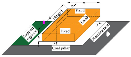
Figure 1.
Thin plate model of direct roof in heading face.
According to the mechanical model in Figure 1 and the boundary conditions:
According to Galerkin’s method [30], the deflection expression is set as:
where C1 is a constant, and ω1 is the first-order deflection function:
The above equation satisfies all boundary conditions.
According to the principle of virtual work:
where A is the integral interval; D is the bending stiffness; , where E is the elastic modulus, and μ is Poisson’s ratio; is the heavy harmonic operator; q is the roof load.
By substituting Equations (2) and (3) into Equation (4), constant C1 can be obtained by integration, and then the deflection ω can be expressed as:
Then, the expressions of each stress component and internal force can be obtained from Equations (6) and (7):
2.2. Analysis of Deformation and Stress Characteristics of the Roof in Heading Face
The commercial mathematics software MATLAB R2021a produced by MathWorks company (Natick, MA, USA) was used to compile the above formula, and the main calculation parameters shown in Table 1 were selected to analyze the deformation and stress characteristics of the unsupported roof in the heading face.

Table 1.
Main calculation parameters.
Figure 2 shows the deflection distribution diagram of the unsupported roof in the heading face.
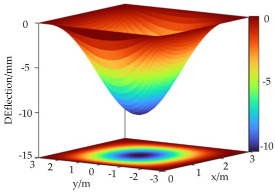
Figure 2.
Deflection distribution characteristic of unsupported roof in heading face.
It can be seen from Figure 2 that, under the action of uniform load q and boundary conditions, the deflection of the roof in the heading cavity head area is symmetrical around the middle line of the roadway width, and the deflection of the side near the simply supported edge is larger, with a maximum value of 11 mm at (1.4, 0).
The distribution law of roof stress and the internal force in the heading face is shown in Figure 3.
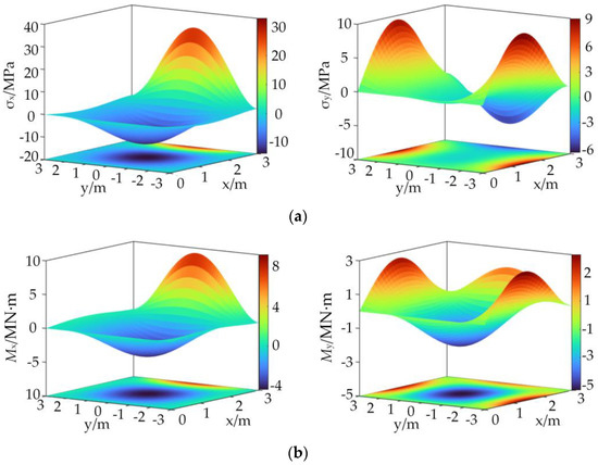
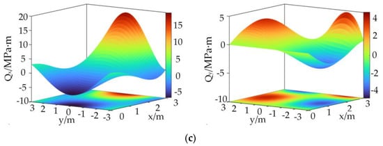
Figure 3.
Distribution of roof stress and internal force in heading face: (a) stress; (b) ending moment; (c) transverse shear stress.
According to the distribution of each stress and the internal force in Figure 3, it can be seen that the maximum values of tensile stress on the fixed supported edges (3, 0) and (1.4, ±3) are the tensile stress values of σx = 34.8 MPa and σy = 6.7 MPa, respectively, and the corresponding bending moments are Mx = 9.8 MN∙m and My = 1.8 MN∙m, respectively. The maximum values of compressive stress appear on (1.4, 0) and (3,0), which are σx = −14.7 MPa and σy = −7.0 MPa, respectively, and the corresponding bending moments are Mx = −4.6 MN∙m and My = 2.0 MN∙m, respectively. The maximum value and minimum value of the transverse shear Qx at (0, 0) and (3, 0) are Qx = −6.3 MPa∙m and Qx = 19.6 MPa∙m, respectively, and the maximum value and minimum value of the transverse shear Qy at (1.4, −2.1) and (1.4, 2.1) are Qy = ±3.5 MPa∙m, respectively.
As shown in Figure 4, the relationship between the unsupported distance and roof stress in the heading face shows that changes in the roof stress and bending moment are basically consistent in the unsupported roof distance model. The roof stress and bending moment increase with the increase in the unsupported distance. The maximum value of the maximum tensile stress and the corresponding bending moment appears at the fixed supported edge. The difference is that the maximum value of the roadway axial direction (x direction) is located at the midline of the roadway width, and the maximum value of the roadway inclination direction (y direction) is close to the simply supported edge. The maximum compressive stress and corresponding bending moment appear in the center of the roof, but the compressive stress in the axial direction of the roadway is closer to the simply supported edge. Since the roof is compressive, not tensile, the fixed edge will be the first to undergo tensile failure, leading to roof instability. As the unsupported distance increases, the transverse shear stress of the roof will also increase. The transverse shear stress in the axial direction of the roadway is monotonic, and the maximum value appears at the boundary of both sides. However, the transverse shear stress on the roadway inclination is not monotonic, it will first increase and then decrease from the fixed supported edge to the roadway center, and the maximum value appears near the fixed supported edge. To summarize, in the process of site construction, it is necessary to first support the most dangerous area.
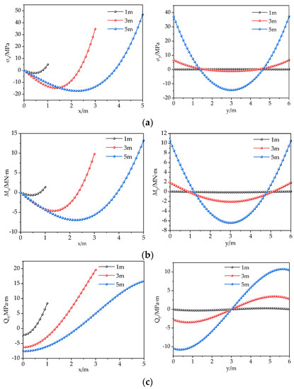
Figure 4.
Relationship between roof force and unsupported distance in heading face: (a) stress; (b) bending moment; (c) transverse shear stress.
3. Analysis of Roof Stability in Heading Face
3.1. Numerical Model
Using FLAC3D software from ITASCA (Minneapolis, MN, USA), a numerical model was established according to the typical geological conditions of the Caojiatan Coal Mine. The numerical model and the thickness are shown in Figure 5. The roadway is driven along the coal seam floor, and the mechanical parameters of the coal seam, roof, and floor are shown in Table 2. The elastic modulus and Poisson’s ratio of each rock layer were obtained by reducing the uniaxial compression test results in the laboratory. The reduction criteria were GSI and the Hoek–Brown failure criterion. The buried depth of the roadway was 300 m, the vertical stress was 7.5 MPa, and the maximum and minimum horizontal principal stresses were 2.0 and 1.2 times the vertical stresses, respectively. The maximum horizontal principal stress was perpendicular to the axial direction of the roadway. The roadway section was rectangular with a width of 5.5 m and a height of 4.5 m. According to the size of the roadway section and the influence range of the heading face, the model size was selected as width × height × thickness = 55.5 × 50 × 25 m. The normal displacements of the four sides and the bottom surface of the model were fixed, and the stress boundary was used for the top surface to simulate the overburden pressure.
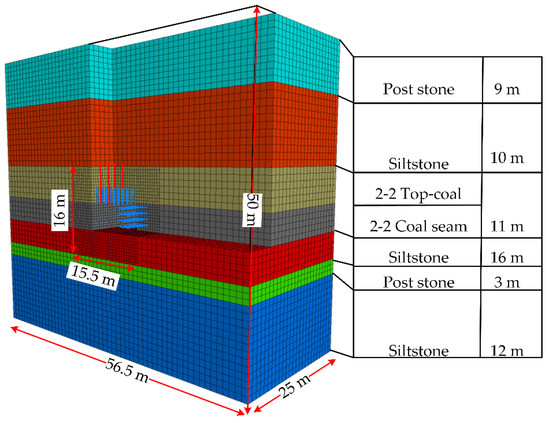
Figure 5.
Numerical model.
Table 2.
Roof and floor strata around simulated entry and mechanical parameters.
In order to simulate the evolution process of the stress and displacement fields of the heading face, a tunnel was excavated and supported step by step, and 25 excavation and supporting steps were divided, with each step excavating 1 m. The bolts and cables were simulated by a cable structure unit built in Flac3D 5.0. The diameter of the bolt was 20 mm, and the length was 2400 mm. The cable was 17.8 mm in diameter and 6500 mm in length. Roof bolt row spacing was 1000 mm, each row with six bolts, with 1000 mm spacing, and all the bolts had a vertical roof arrangement. Two sides had a bolt row spacing of 1000 mm, each row with four bolts, with 1000 mm spacing, and all were in the vertical roadway arrangement. Roof anchor cables were arranged 2-0-0-2, spacing was 2400 mm, row spacing was 3000 mm, and all were in the vertical roadway roof arrangement.
3.2. Stress and Deformation Distribution Characteristics of Roof in Heading Face
The distribution of the principal stress tensor during excavation is shown in Figure 6. The displacement distribution is shown in Figure 7. The three-way stress change curve at 1 m above the center of the roof is shown in Figure 8. The relation curve between the roadway roof displacement and the distance to the heading face is shown in Figure 9.
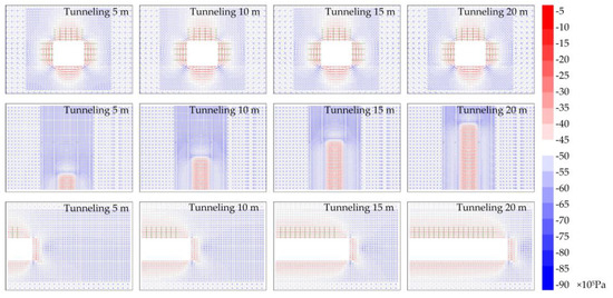
Figure 6.
Distribution characteristics of principal stress tensor of heading face (stained with σ1).
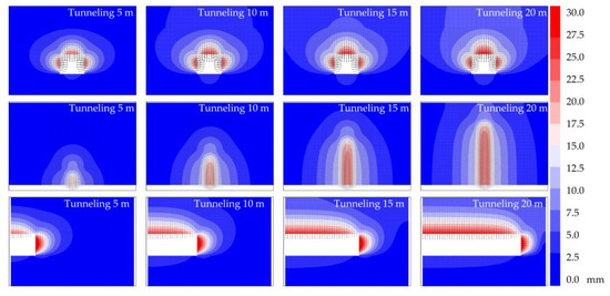
Figure 7.
Displacement distribution characteristics of heading face.
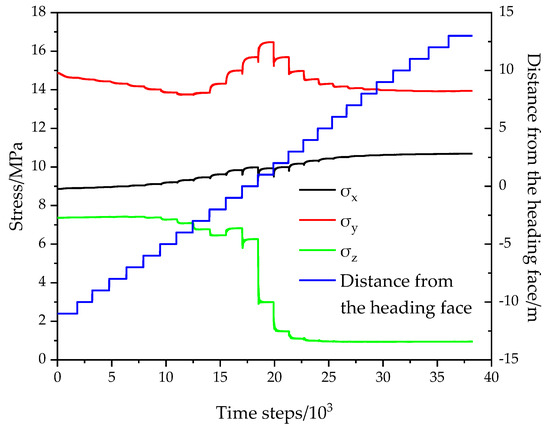
Figure 8.
Three-way stress change curve of roof in heading face.
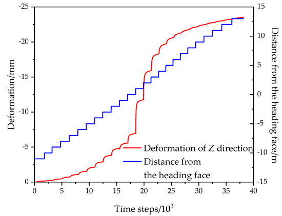
Figure 9.
Relationship between roof displacement and heading face position.
It can be seen from Figure 6, Figure 7, Figure 8 and Figure 9 that after roadway excavation, the stress around the heading face was redistributed. The stress concentration zone appeared around the top angle of the roadway heading face, and the stress reduction zone appeared in the front and rear roofs of the caving face. The stress reduction area in the front of the working face was small and changed little with the advance of the working face. In the rear of the working face, the stress reduction area within 2 m adjacent to the working face was small. With the continuous expansion away from the working face, the stress increase area was constantly transferred to the deep surrounding rock, and the stress distribution basically remained stable after a certain distance. The horizontal stress at 1 m above the middle of the roof and the axial stress of the roadway first increased and then decreased with the increase in the operation time step, while the vertical stress was always in a downward trend. The displacement of the roof began to obviously increase when the advanced working face was equal to the roadway width. In the newly excavated 2 m range, the roof and floor displacements were small, and the distribution range was not large. With the further distance away from the heading face, the roof subsidence continuously increased, and the displacement of the surrounding rock was basically stable when the roadway width reached 2 times.
3.3. Analysis of Influencing Factors for Roof Stability of Heading Face
A test scheme was designed with the parameters of ground stress level, surrounding rock strength, different roadway sections, and different unsupported distances. According to the vertical stress, the ground stress level was set as 3.75 MPa, 7.5 MPa, 15 MPa, and 25 MPa, corresponding to the buried depth of 150 m, 300 m, 600 m, and 1000 m, respectively. The maximum and minimum horizontal principal stresses were still set as 2.0 and 1.2 times the vertical stresses. The roof strength was characterized by cohesion, respectively, set at 0.5 MPa, 3.5 MPa, 6.5 MPa, and 9.5 MPa. The section size is represented by the roadway width, and four groups of schemes with roadway widths of 3.5 m, 4.5 m, 5.5 m, and 6.5 m were, respectively, set. As for the unsupported distance, four groups of schemes with void head distances of 1 m, 3 m, 5 m, and 12 m were set. The size and boundary conditions of the test model were the same as those of the aforementioned model, and the test scheme is listed in Table 3.
Table 3.
Roof and floor strata relative to simulated entry and mechanical parameters.
The regression analysis of each factor was carried out according to the roof displacement, and the results are shown in Figure 10.
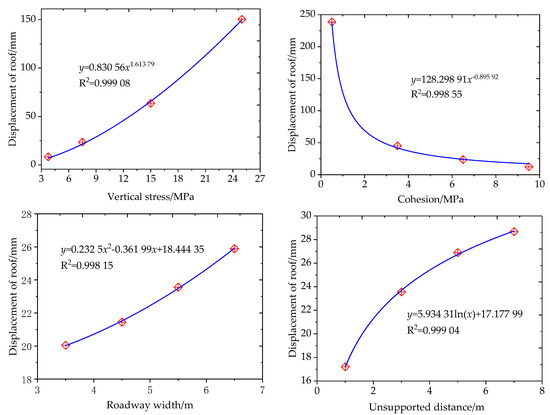
Figure 10.
Fitting curve of single factor displacement of heading face roof.
The roof subsidence had an exponential relationship with the stress level, and the subsidence increased with the increase in stress. It had a negative exponential relationship with the strength of the surrounding rock and significantly decreased with the increase in the strength of coal and rock in a certain range. However, when the strength exceeded a certain value, the amount of subsidence could not be effectively reduced by increasing again. It had a quadratic functional relationship with the roadway section and increased with the increase in roadway width. It had a logarithmic relationship with the void top distance. With the increase in void top distance, the amount of subsidence gradually increased.
3.4. Influence of Support on Roof Stability of Heading Face
In the basic model, the bolt and anchor cable supports were installed all in one step after the heading face was drilled for 3 m. In order to improve the speed of the heading, the setup of the support was divided into two steps. After the roadway was excavated, some of the bolts were first installed, and all the bolts and cables were set up behind the boring machine. According to the above analysis, the support system should first be set up at the side of the fixed boundary, so the fractional bolt and cable support scheme shown in Figure 11 was simulated. When the heading face was drilled for 3 m, the four bolts near the two sides were first installed on the roof. Then, after the heading face was gradually pushed forward for 12 m, the two bolts and cables located in the alley at 1 m position were completed and excavated.
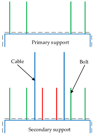
Figure 11.
Schematic diagram of roof support completed in two steps.
The relation curve between the roadway roof displacement and distance to the heading face under the basic model and the fractional support model is shown in Figure 12. Due to the untimely support of some of the bolts and cables, the roof displacement of the fractional support was greater than that of the basic model’s support installed in one step. It can be seen that improving the heading speed by dividing support was at the cost of influencing the supporting effect of the bolt and cable. At the same time, a numerical test with an unsupported distance of 12 m was also carried out. Compared with the fractional support, the roof subsidence when the void roof distance was 12 m was larger than that of the one-step installed support of 12 m. Therefore, the initial partial support in the fractionated support still played a certain role in controlling the roof stability, and its action mechanism was as follows: The roof span was reduced in time, and the confining pressure was partially restored. It can be seen that under certain geological and production conditions, the use of fractional support can not only effectively maintain the stability of the roadway but also speed up the heading speed.
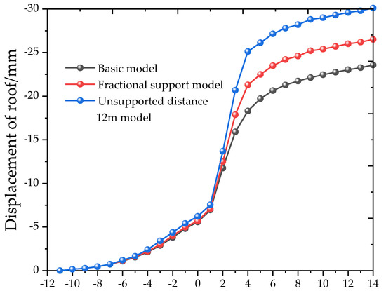
Figure 12.
Curve between roadway roof displacement and distance to heading face.
4. Engineering Verification
4.1. Geological Overview
The 122,110 working face of the Caojiatan Coal Mine mainly exploits a 2-2 coal seam [31,32]. As shown in Figure 13, the thickness of the 2-2 coal seam is 9.68~11.69 m, the average thickness is 10.63 m, the roof is siltstone with an average thickness of 11.00 m and post stone of 9.54 m, the floor is siltstone with an average thickness of 4.67 m and post stone of 2.43 m, the buried depth is 316.19~344.93 m, the average buried depth is 333.43 m, and the auxiliary transportation roadway of this working face is a rectangular roadway with a section width of 6.50 m and a height of 4.55 m. During the heading period, the roadway is driven along the floor, and the thickness of the top coal is about 6 m.
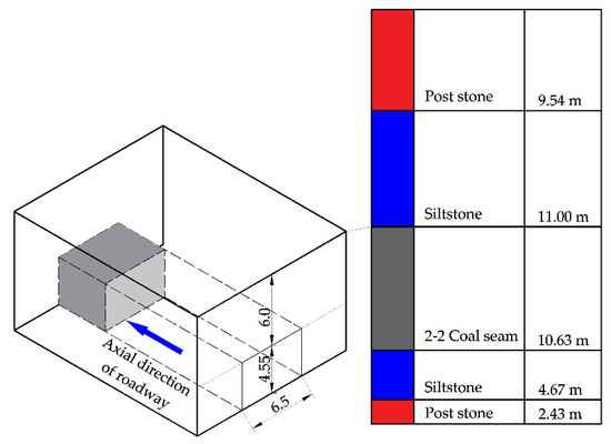
Figure 13.
Geological survey of 122,110 auxiliary transport roadway.
The Caojiatan Coal Mine has simple geological conditions and is less affected by tectonic areas. However, the thickness of the coal seam is large, the roadway is driven along the floor, the direct roof is the coal body with low strength, and the roadway section is large. When the roof support with a more conservative support scheme was adopted, the construction process restricted the heading speed, but once a long unsupported distance and weakly supported scheme were chosen, the excavation disturbance of the large section roadway and the unloading effect often resulted in a larger range of surrounding rock damage and fracture extension and even roof falling phenomenon [33,34], also limiting the heading speed. Hence, it is necessary to find the balance between supporting parameters and the surrounding rock stability, determine the reasonable heading and supporting parameters, and improve the heading speed.
4.2. Roadway Construction Technology and Process
Following a previous study, an EJM270/4-2-type excavating anchor machine was used to cut and support the roof during the heading of the 122,110 auxiliary transport roadway in the field application. The method of split support was adopted to realize parallel operation between cutting and supporting the roof bolts. As shown in Figure 14, the row distance between roof bolts was 1200 × 1000 mm, and there were six supporting bolts on the roof, numbered ①, ②, ③, ④, ⑤, ⑥ from left to right. The excavation-and-anchor combined unit first supported ①, ②, ⑤, and ⑥ roof bolts, and the bolt trolley made up the remaining ③ and ④ roof bolts by adjusting the position of the slip frame of the drilling rig. Roof bolts ①, ②, ⑤, and ⑥ provided permanent support with a minimum roof control distance of ≤2 m and maximum roof control distance of ≤3 m; roof bolts ③ and ④ had permanent support lags ①, ②, ⑤, and ⑥ bolts at 12 m. The row spacing between the roof anchor cables was 2400 × 3000 mm, with two top anchor cables in each row. The minimum distance of the anchorage cable’s permanent support to the head was 21.8 m, and the maximum was 22.8 m. The field application showed that the monthly footage reached more than 1000 m.
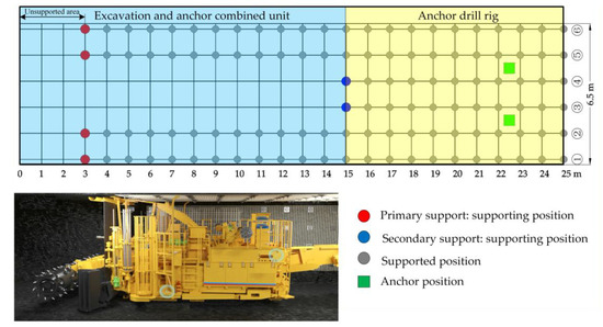
Figure 14.
The 122,110 auxiliary transport roadway heading and support diagram.
4.3. Monitoring and Analysis of Roof Deformation during Heading
An AKM-20 acoustic multipoint displacement meter was used for the monitoring of the tunnel surrounding roof deformation. During the monitoring, a magnetic anchorage head was installed in the designated position of the surrounding rock. Through the electromagnetic principle, the acoustic probe received the position information of the magnetic ring installed in the rock mass to monitor the movement and deformation of the surrounding rock inside, as shown in Figure 15.
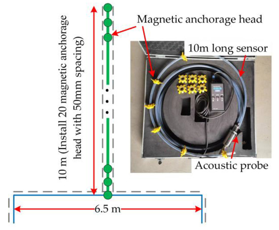
Figure 15.
Schematic diagram of acoustic multipoint displacement meter equipment and roof installation.
It can be seen from Figure 16 that the roof was stable, and the deformation was small in the heading influence period. The maximum deformation of the roof was 18 mm, and the deformation mainly occurred in the early stage of the surrounding rock exposure. In the first 3 hours of monitoring, the deformation of the roof and the two sides, respectively, reached 78% of the total deformation when the excavation of the 122,110 auxiliary transportation roadway was completed (at this time, the excavation working face had been pushed 836 m past the measuring station). At the same time, it can be seen from Figure 9 that the surrounding rock deformation occurred gradually, the shallow surrounding rock deformation was large, the deep surrounding rock deformation was small, and the deformation range of the roof during the heading period was about equal to the roadway span.
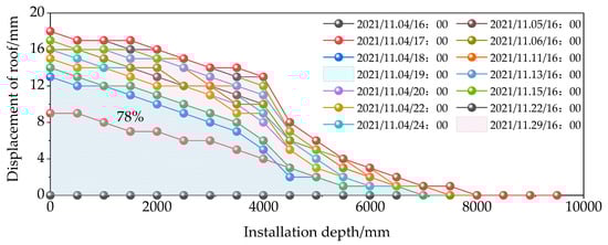
Figure 16.
Measured curve of roof displacement during heading of 122110 auxiliary transportation roadway.
5. Discussion and Conclusions
5.1. Discussion
In view of the shortcomings of the existing research, this paper established a mechanical model of the heading face roof based on the thin plate theory. Through analyzing the deflection, stress, and internal force of the roof, it was proposed that the position near the fixed supported edge should be supported first in the field construction process. Through a FLAC3D numerical simulation, the main influencing factors of roof stability in the heading face were analyzed, including ground stress, surrounding rock strength, roadway section, void roof distance, etc., and the regression analysis of each factor was carried out by evaluating the amount of roof subsidence. It was found that the roof displacement had a positive exponential relationship with stress level, a negative exponential relationship with the surrounding rock strength, a quadratic functional relationship with the roadway section, and a logarithmic relationship with void roof distance. In the fractional support model, the initial partial support could timely reduce the roof span and partially recover the confining pressure. Under certain geological and production conditions, the use of fractional support can not only effectively maintain the stability of the roadway but also speed up the heading speed.
5.2. Conclusions
In this paper, through theoretical analysis and numerical simulation, the roof stability of the heading face was studied. Finally, the research results were revealed for the 122,110 working face auxiliary transport roadway of the Caojiatan Coal Mine, and the following conclusions were drawn:
- (1)
- The analytical formula of the roof deflection, stress, and internal force of the heading face was derived from the thin plate theory. It was found that the largest tensile stress and the corresponding bending moment in the fixed boundary in the roof, the maximum compressive stress, and the corresponding maximum bending moment appeared in the center of the roof and slightly closer to the hinged boundary. The transverse shear stress in the axial direction of the roadway was monotonic; however, the transverse shear stress on the roadway inclination was not monotonic, and it first increased and then decreased from the fixed support edge to the roadway center. Thus, it is necessary to first support the position close to the fixed support edge.
- (2)
- After roadway excavation, the stress concentration zone appeared at the top angle of the heading face, and the stress reduction zone appeared in the middle of the front and rear roofs of the working face. The displacement of the surrounding rock began to obviously increase when the advanced working face was equal to about half of the roadway width. In the newly excavated 2 m range, the roof and floor displacements were small. With the increasing displacement of the surrounding rock away from the heading face, it was basically stable when it reached 2 times the roadway width.
- (3)
- The main factors affecting the roof stability of the heading face were studied, including ground stress, surrounding rock strength, section size, and unsupported distance. The regression analysis of each factor was carried out according to the roof subsidence. The roof subsidence had a positive exponential relationship with the stress level, a negative exponential relationship with the surrounding rock strength, a quadratic functional relationship with the roadway section, and a logarithmic relationship with the unsupported distance.
- (4)
- Due to the untimely support of some of the bolts and cables, the displacement of the surrounding rock was greater than that of the one-step installed support but less than that of the same long unsupported distance roof model. It can be seen that the initial local support in the fractional support still had a certain effect on the control of roof stability, and its action mechanism was as follows: The roof span was reduced in time, and the confining pressure was partially restored. Therefore, under certain geological and production conditions, the use of fractional support can not only effectively maintain the stability of the roadway but also speed up the heading speed.
- (5)
- According to the theoretical analysis and numerical simulation results, field verification was carried out. The 122,110 working face of the Caojiatan Coal Mine’s auxiliary transportation roadway adopted the divided support. The maximum roof subsidence was 18 mm, the roof was stable, and the monthly progress was more than 1000 m, which significantly improved the roadway heading speed.
Author Contributions
Conceptualization, C.S.; methodology, C.S. and P.J.; software, C.S. and C.L.; validation, P.J. and P.G.; formal analysis, C.L. and Y.L.; investigation, C.S. and P.L.; resources, C.L.; data curation, C.S.; writing—original draft preparation, C.S.; writing—review and editing, C.L.; visualization, C.S.; supervision, P.G.; project administration, P.G.; funding acquisition, P.J. and P.G. All authors have read and agreed to the published version of the manuscript.
Funding
This article was funded by the National Key R&D Plan of China (grant number 2020YFB1314002), the National Natural Science Foundation of China Youth Foundation Project (grant number 52104091), the Key Foundation of CCTEG Coal Mining Research Institute (grant number KCYJY-2021-ZD-02), and the Applied Basic Research Project of Shanxi Province (grant number 202103021224334).
Data Availability Statement
Not applicable.
Conflicts of Interest
The authors declare no conflict of interest.
References
- Kang, H.P. Seventy years development and prospects of strata control technologies for coal mine roadways in China. Chin. J. Rock Mech. Eng. 2021, 40, 1–30. [Google Scholar]
- Kang, H. Support technologies for deep and complex roadways in underground coal mines: A review. Int. J. Coal Sci. Technol. 2014, 1, 261–277. [Google Scholar] [CrossRef]
- Li, P.; Lai, X.P.; Gong, P.L.; Su, C.; Suo, Y.L. Mechanisms and Applications of Pressure Relief by Roof Cutting of a Deep-Buried Roadway near Goafs. Energies 2020, 13, 5732. [Google Scholar] [CrossRef]
- Wang, B.K. Current status and trend analysis of roadway driving technology and equipment in coal mine. Coal Sci. Technol. 2020, 48, 1–11. [Google Scholar]
- Sun, L.; Wu, H.; Yang, B.; Li, Q. Support failure of a high-stress soft-rock roadway in deep coal mine and the equalized yielding support technology: A case study. Int. J. Coal Sci. Technol. 2015, 2, 279–286. [Google Scholar] [CrossRef]
- Zhang, Z.G. Development tendency and key technology of mine seam gateway rapid driving system. Coal Sci. Technol. 2016, 44, 55–60. [Google Scholar]
- Kang, H.P.; Wang, J.H.; Lin, J. High pretensioned stress and intensive bolting system and its application in deep roadways. J. China Coal Soc. 2007, 32, 1233–1238. [Google Scholar]
- Kang, H.P.; Wang, J.H.; Lin, J. Case studies of rock bolting in coal mine roadways. Chin. J. Rock Mech. Eng. 2010, 29, 649–664. [Google Scholar]
- Kang, H.P. Sixty years development and prospects of rock bolting technology for underground coal mine roadways in China. China Univ. Min. Technol. 2016, 45, 1071–1081. [Google Scholar]
- Kang, H.P.; Jiang, P.F.; Wu, Y.Z.; Gao, F.Q. A combined “ground support-rock modification-destressing” strategy for 1000-m deep roadways in extreme squeezing ground condition. Int. J. Rock Mech. Min. 2021, 142, 104746. [Google Scholar] [CrossRef]
- Liu, C.; Jiang, P.F.; Wang, Z.Y.; Wei, Y.Z.; Luo, C.; Guo, J.C. Raesearch on current situation of rapid driving technology in coal roadway and its assessment method of application effect. Coal Sci. Technol. 2020, 48, 26–33. [Google Scholar]
- Mao, J.; Wu, C.T.; Xie, M. Advances and trends on boom-type excavators. Chin. J. Constr. Mach. 2007, 5, 240–242. [Google Scholar]
- Wu, Y.Z.; Wu, J.X.; Wang, F. Mechanism and application of excavation, support and bolting continuous parallel operation in roadway. Coal Sci. Technol. 2016, 44, 39–44. [Google Scholar]
- Wang, H. The 40 years developmental review of the fully mechanized mine roadway heading technology in China. J. China Coal Soc. 2010, 35, 1815–1820. [Google Scholar]
- Wang, H.; Wang, J.L.; Zhang, X.F. Theory and technology of efficient roadway advance with driving and bolting integration. J. China Coal Soc. 2020, 45, 2021–2030. [Google Scholar]
- Ma, H.W.; Wang, S.B.; Mao, Q.H.; Shi, Z.W.; Zhang, X.H.; Yang, Z.; Cao, X.G.; Xue, X.S.; Xia, J.; Wang, C.W. Key common technology of intelligent heading in coal mine roadway. J. China Coal Soc. 2021, 46, 310–320. [Google Scholar]
- Ma, Z. Current situation and development trend of the integrated equipment of digging and anchoring. Colliery Mech. Electr. Technol. 2020, 41, 11–13+17. [Google Scholar]
- Ma, P.; Qian, D.; Zhang, N.; Shimada, H.; Pan, D.; Huang, K. Application of Bolter Miner Rapid Excavation Technology in Deep Underground Roadway in Inner Mongolia: A Case Study. Sustainability 2020, 12, 2588. [Google Scholar] [CrossRef]
- Fan, M.J. Determination of reasonable unsupported roof distance in deep coal mine roadway tunneling with large-section. Coal Technol. 2016, 35, 60–62. [Google Scholar]
- Ma, R. The Roof Failure Mechanism and Stability Control of the Roof in the Empty Roof Area of Rapid Roadway Excavation. Ph.D. Thesis, China University of Mining and Technology, Xuzhou, China, 2016. [Google Scholar]
- Wu, P.Q. Research on the self-stabilization law of the empty roof and optimization of the construction plan for the rapid excavation of coal roadways. Master’s Thesis, China University of Mining and Technology, Xuzhou, China, 2017. [Google Scholar]
- Tang, W.T.; Li, S.Y.; Liu, W.; Wang, Z.F. Study on unsupported roof distance of roadway driving with broken roof. Saf. Coal Mines 2013, 44, 38–40+44. [Google Scholar]
- Bai, J.B.; Xiao, T.Q.; Li, L. Unsupported roof distance determination of roadway excavation using difference method and its application. J. China Coal Soc. 2011, 36, 920–924. [Google Scholar]
- Yang, S.; Hua, X.; Liu, X.; Li, C.; Wang, S. Analysis of Stability Factors of Roadway Roof and Determination of Unsupported Roof Distance. Shock Vib. 2021, 2021, 2271257. [Google Scholar] [CrossRef]
- Yang, S.; Hua, X.; Liu, X.; Wang, E.; Li, C.; Zhang, X. Deformation and Failure Characteristics of the Roof in an Unsupported Area during Rapid Driving of Coal Roadway. Shock Vib. 2021, 2021, 7275334. [Google Scholar] [CrossRef]
- Chu, X.W.; Wu, Y.Z.; Wu, Z.G.; Wu, Z.G.; Hao, D.Y.; Feng, Y.L.; Li, W.Z.; Meng, X.Z. Characteristics of roof deformation in excavating face and determination method of reasonable non-support distance. J. Min. Saf. Eng. 2020, 37, 908–917. [Google Scholar]
- Kang, H.P.; Jiang, P.F.; Gao, F.Q.; Wang, Z.Y.; Liu, C.; Yang, J.W. Analysis on stability of rock surrounding heading faces and technical approaches for rapid heading. J. China Coal Soc. 2021, 46, 2023–2045. [Google Scholar]
- Kang, H.P.; Wang, J.H.; Gao, F.Q. Stress distribution characteristics in rock surrounding heading face and its relationship with supporting. J. China Coal Soc. 2009, 34, 1585–1593. [Google Scholar]
- Yi, K.; Liu, Z.; Lu, Z.; Zhang, J.; Dong, S. Effect of Axial In-Situ Stress in Deep Tunnel Analysis Considering Strain Softening and Dilatancy. Energies 2020, 13, 1502. [Google Scholar] [CrossRef]
- Wu, J.L. Elasticity; Higher Education Press: Beijing, China, 2001. [Google Scholar]
- Wang, R.; Cheng, L. Research and application of intelligent fast-moving continuous transport system in Caojiatan Coal Mine. J. Intell. Mine 2022, 3, 82–86. [Google Scholar]
- Hua, Z.L.; Li, J.M. Analysis on the surface movement law of the first mining face in Caojiatan coal mine. Shaanxi Coal 2020, 39, 131–134. [Google Scholar]
- Zhang, G.H. Surrounding rock control technology for rapid excavation of large section full coal roadway in Caojiatan Coal Mine. Shaanxi Coal 2022, 41, 138–141. [Google Scholar]
- Zhao, Y.; Wang, L.; Wang, Z.C. Research on surrounding rock deformation mechanism and support technology of large section roadway. Shaanxi Coal 2021, 40, 57–61. [Google Scholar]
Publisher’s Note: MDPI stays neutral with regard to jurisdictional claims in published maps and institutional affiliations. |
© 2022 by the authors. Licensee MDPI, Basel, Switzerland. This article is an open access article distributed under the terms and conditions of the Creative Commons Attribution (CC BY) license (https://creativecommons.org/licenses/by/4.0/).