Article

Possibilities of Using Zeolites Synthesized from Fly Ash in Adsorption Chillers

1
Faculty of Energy and Fuels, AGH University of Science and Technology, Mickiewicza 30, 30-059 Krakow, Poland
2
Department of Chemical Engineering, Instituto Superior Tecnico, Av. Rovisco Pais 1, 1049-001 Lisbon, Portugal
*
Author to whom correspondence should be addressed.
Energies 2022, 15(19), 7444; https://doi.org/10.3390/en15197444
Submission received: 19 August 2022 / Revised: 23 September 2022 / Accepted: 4 October 2022 / Published: 10 October 2022
(This article belongs to the Special Issue Biomass and Waste Conversion: Latest Advances and Prospects)

Abstract

:
Adsorption chillers produce cold energy, using heat instead of electricity, thus reducing electrical energy consumption. A major industrial waste, fly ash, can be converted to zeolite and used in adsorption chillers as an adsorbent. In this research, three different types of zeolites were synthesised from fly ash via a hydrothermal reaction in an alkaline solution (NaOH). The obtained samples (Na-A zeolites) were modified with K2CO3 to increase the water adsorption capacity of these samples. Phase and morphology analyses shows that desired zeolites formed properly but other crystalline phases also exist along with nonporous amorphous phases. The determined specific surface areas for Na-A zeolite (12 h) and Na-A zeolite (24 h) are 45 m2/g and 185 m2/g respectively, while the specific surface area for synthesized 13X zeolite is almost negligible. Water-isotherm for each of these samples was measured. Considering the application of adsorption chillers, average adsorption capacity was very low, 1.73% and 1.27%, respectively, for the two most probable operating conditions for synthesized 13X zeolite, whereas no water was available for the evaporation from Na-A zeolite (12 h) and Na-A zeolite (24 h). This analysis implies that among the synthesized materials only 13X zeolite has a potential as an adsorber in sorption chillers.

1. Introduction

Modern civilization is driven mostly by energy. The development and application of the latest technologies largely depend on non-renewable energy. The main sources of this energy are fossil fuels, such as natural gas, oil and coal. There are two main problems associated with the consumption of fossil fuels. The first one is the scarcity of these sources, as they are running out quickly. Secondly, the consumption of fossil fuels is the main reason for the greatest environmental problems associated with releases of greenhouse and hazardous combustion by various products, including CO2, NOx, SO2, heavy metals and dust. Moreover, the demand for energy is increasing day by day. Therefore, the development of sustainable energy systems is both needed and required.
Due to serious climate changes and an urgent need to increase thermal comfort in indoor spaces, the demand for cooling is increasing rapidly. Common air-conditioning and refrigeration systems are usually driven by electricity. Between 2003 and 2004, the electricity used for air conditioning in USA constituted 15.4% of total electricity consumption. In Shanghai city, China, the electricity used for air conditioning constituted 45 to 56% of total electricity consumption in the summer of 2010 [1]. In 2019, 8.5% of total generated electricity was used for space cooling. Energy demand for this purpose has increased more than three times from 1990 [2]. It demonstrates how fast the demand for space cooling is growing and will grow in the future. It has been projected that the number of air-conditioning units will increase up to 5600 million in 2050 from almost 1600 million in 2016, with significant increases in countries such as China and India [3]. So, electricity consumption will also increase for the purpose of space cooling. This electricity mainly comes from fossil fuels. In the year 2018, coal, natural gas and oil constituted 39%, 26% and 3% of total electricity generation [4]. Additionally, electricity production has low efficiency, around 40–50%, and the temperature of the waste heat ranges between 70–200 °C [1]. It ultimately affects the environment. Furthermore, chlorofluorocarbons (CFC), which was used for refrigeration, caused significant damage to ozonosphere, which stops the dangerous ultraviolet rays that originate from the sun. Hydrochlorofluorocarbons (HCFC) are only a temporary alternative because they also create a greenhouse effect and cause damage to the ozonosphere [1].
Renewable energy resources, such as solar energy and geothermal energy, together with waste energy resources with low to very low temperature ranges are available. An adsorption chiller can be employed to utilize these small temperature range heat resources. There are existing sorption refrigeration and heat pump technologies that can be run with such low-grade heat and also use environmentally friendly refrigerants [1]. Adsorption refrigeration technologies can use different adsorbents which can be operated with low-grade heat, for instance, the zeolite–water pair works in the range of 70–250 °C, silica gel–water pair works in the range of 55–120 °C, the activated carbon–methanol pair the works up to a temperature of 120 °C and the activated carbon–ammonia pair usually works up to temperatures of 150 °C (can be used even for 200 °C or more) [1,5]. The commonly used refrigerants are water, ammonia, methanol, etc. These are called green refrigerants because they have no ozonosphere depletion potential (ODP) or greenhouse warming potential (GWP). Additionally, the adsorption refrigeration system has other advantages over absorption systems, e.g., this equipment does not include a solution pump and rectification equipment. Moreover, solution crystallization is absent for such a system. However, there are additional drawbacks as well. Adsorption refrigeration is not as efficient as absorption refrigeration and the volume and mass of this system is also large [1].
The silica gel–water adsorption chiller has been marketed successfully, but there is still much space for improvement in the adsorption refrigeration system. The focus should be given to the factors that can improve the performance of adsorption refrigeration technology, such as adsorption working pairs and their working mechanisms, the structure and design of adsorption refrigeration devices, the improvement of heat and the mass transfer of the adsorption/regeneration bed, etc. [1].
The presented study is dedicated to the analysis of fly ash-derived zeolites as potential candidates for an adsorption chiller. Zeolites are microporous materials that contain aluminium, silicon and oxygen in their main three-dimensional, crystalline structure and also carry cations and water [6]. The general chemical formula of zeolite is as follows: My/n[(AlO2)y(SiO2)m]zH2O [1]. The water contained in pores and cavities in the structural composition of zeolites can be removed upon the application of heat [7]. High thermal and mechanical stability make zeolites proper candidates for adsorption chiller adsorbents, usually in a working pair with water. This working pair is characterised by a heat of adsorption equal to 3200–4200 kJ/kg [1].
In the tetrahedral structure, zeolite includes silicon cations (Si4+) and aluminium cations (Al3+). These ions are bonded with four oxygen anions (O2−). Thus, oxygen ions connect the tetrahedrons. The ratio of Si:O is 1:2 [7].
The Na-A zeolite is one of the aluminosilicate molecular sieves with a Si/Al ratio of 1, also known as Linde Type A with the composition (Na+12(H2O)27|8[Al12Si12O48]8 [8]. The framework includes β-cages (SOD) and α-cages (supercages). Four-membered rings (D4R) link the β-cages with each other and form an inner cavity [9]. The diameter of the super cage is 11.4 Å and the aperture size is 4.1 Å. The Na+ ion can be replaced with K+, reducing the pore opening, and replaced by Ca2+, increasing the pore opening [8]. It can be used as a desiccant, catalyst and also in cation exchange [8,10].
The Na-X zeolite has a Si/Al ratio that varies from 1 to 1.5 with a faujasite-type (FAU) structure that has the chemical formula (Ca, Mg, Na2)29 (H2O)240|[Al58Si134O384] [11]. The framework includes β-cages (SOD) and α-cages (supercages). Double six-membered rings (D6R) link the β-cages with each other and form an inner cavity [9]. The diameter of the super cage is 13 Å and the aperture size is 8 Å [9,12]. There are several uses of the FAU type zeolites, such as ion exchangers, adsorbents or catalysts, in chemical or oil refining; natural gas purification from sulphur compounds; drying oils and gases; separation of hydrocarbon mixtures; sorption of radio nuclides; etc. [13].
The evaluation of synthetic zeolite production from different materials, such as clay minerals, low carbon materials and fly ashes, allowed the production of new value-added products and their use in industry, in particular the agriculture, biochemical and chemical sectors. The utilisation of fly ash as a feedstock for zeolite synthesis subscribes to waste minimization strategies and circular economy concepts, but it requires the elaboration of special procedures. The most often used and well-known synthesis methods are hydrothermal synthesis, molten salt method, alkali activation and microwave synthesis [14,15].
The performance of the adsorption chiller largely depends on the performance of the adsorption and desorption of the adsorbent, namely the amount of adsorbed refrigerant, the time required to reach equilibrium, the temperature of adsorption and desorption, the heat of adsorption and desorption, the heat and mass transfer of the adsorber bed, etc. [1]. The purposes of the present work included the synthesis of Na-A and 13X zeolite from fly ash and the analysis of the potential application of these adsorbents compared to the performance of silica gel with regard to the adsorption chiller.

2. Material and Methods

2.1. Zeolites Preparation Methods

The fly ash used for zeolite synthesis was collected from a power plant located in Poland. The composition of the fly ash was as follows: SiO2 = 45.50%, Al2O3 = 23.10%, Fe2O3 = 7.38%, CaO = 6.30%, MgO = 4.22%, Active CaO + MgO = 0.55%, S = 0.54%, SO42− = 1.62%, TiO2 = 0.72%, P2O5 = 0.29%, Mn3O4 = 0.17, Na2O = 1.55%, K2O = 2.96 and Combustion Loss = 6.42%. Three types of zeolites were prepared and modified with K2CO3 to further develop the adsorption capacity of these materials.
The procedure of the Na-A zeolite (12 h) preparation was conducted using dry fly ash, which was mixed with NaOH into a mass ratio of 5:6. The mixture was milled and exposed to a temperature of 550 °C in a muffle furnace for 1 h. The mixture after heating was cooled down to room temperature and milled for 1 h. It was then mixed with distilled water at a 4:1 ratio. The obtained slurry was stirred at room temperature for 12 h. After this stage, the mixture (solid and liquid phases) sample crystallization was obtained at 100 °C for 12 h. The obtained zeolite was washed with distilled water to remove NaOH and reach c.a. pH = 7 and filtered. The obtained material was dried at 100 °C for 12 h.
The procedure of the Na-A zeolite (24 h) preparation was similar to the methodology for the Na-A zeolite sample (12 h), but the crystallization time at 100 °C was extended up to 24 h.
Both Na-A zeolites were modified with K2CO3. In this step, the obtained zeolite was mixed with K2CO3 at a ratio of 2:1 (by weight) and dissolved in distilled water at a ratio of 1 g to 5 mL. The obtained slurry was stirred at room temperature for 24 h. Modified zeolite was filtered and dried at 60 °C for 12 h. The last step was the calcination, which was performed in a muffle furnace at 300 °C for 4 h.
During 13X Zeolite preparation, fly ash was first calcined in a muffle furnace at 800 °C to remove the remaining carbon and volatile matter. To enhance the activity, thermal stability and acidity of the zeolite, the removal of Al and Fe was performed by treatment with hydrochloric acid. The calcined sample was treated with 1 M HCl. Dried pre-treated fly ash was then mixed with NaOH at a ratio of 1.5:1 (by weight). This mixture was exposed to 550 °C for 1 h and later cooled down to room temperature. The obtained mixture was milled and distilled water was added at a ratio of 10 g fly ash/100 mL water. The obtained mixture was stirred for 12 h. Then, it was allowed to settle at 90 °C for 6 h. After that, distilled water was used to wash the sample and filtered to remove the remaining sodium hydroxide and was later dried at 100 °C for 12 h.

2.2. Surface Area Analysis

The nitrogen gas adsorption method was used at −196 °C using Gemini V 2.00; model 2380. All the samples were degassed overnight at 250 °C under vacuum before measurement. The surface area of the samples was determined using the BET model.

2.3. Phase Analysis

The analysis of the crystalline phases was carried out by X-ray diffraction using an XRD DX-27mini manufactured by HAOYUAN. Analyses were performed at a 2θ angle measuring range from 5° to 110° with a step of 0.02° 2θ. The tube voltage and the tube current were 35 kV and 12 mA, respectively. The percentage of crystalline phases was determined by a semi-quantitative method and was implemented to Malvern Panalytical’s HighScore Plus software using PDF4+ database (2012 version). The relative intensity of the reflections of the phases was compared with references included in the ICDD database and the phase composition was determined for studied samples.

2.4. Morphology Analysis and Semi-Quantitative Analysis of Synthesised Zeolites Using Scanning Electron Microscopy with Energy Dispersive Spectroscopy (SEM–EDS)

The surface structure of the samples and the chemical composition of selected areas on their surfaces were analyzed using the scanning electron microscopy with energy dispersive spectroscopy (SEM–EDS method). The images and chemical composition analysis (EDS) were performed using a Prisma E scanning electron microscope manufactured by Thermo Scientfic, Waltham, MA, USA.

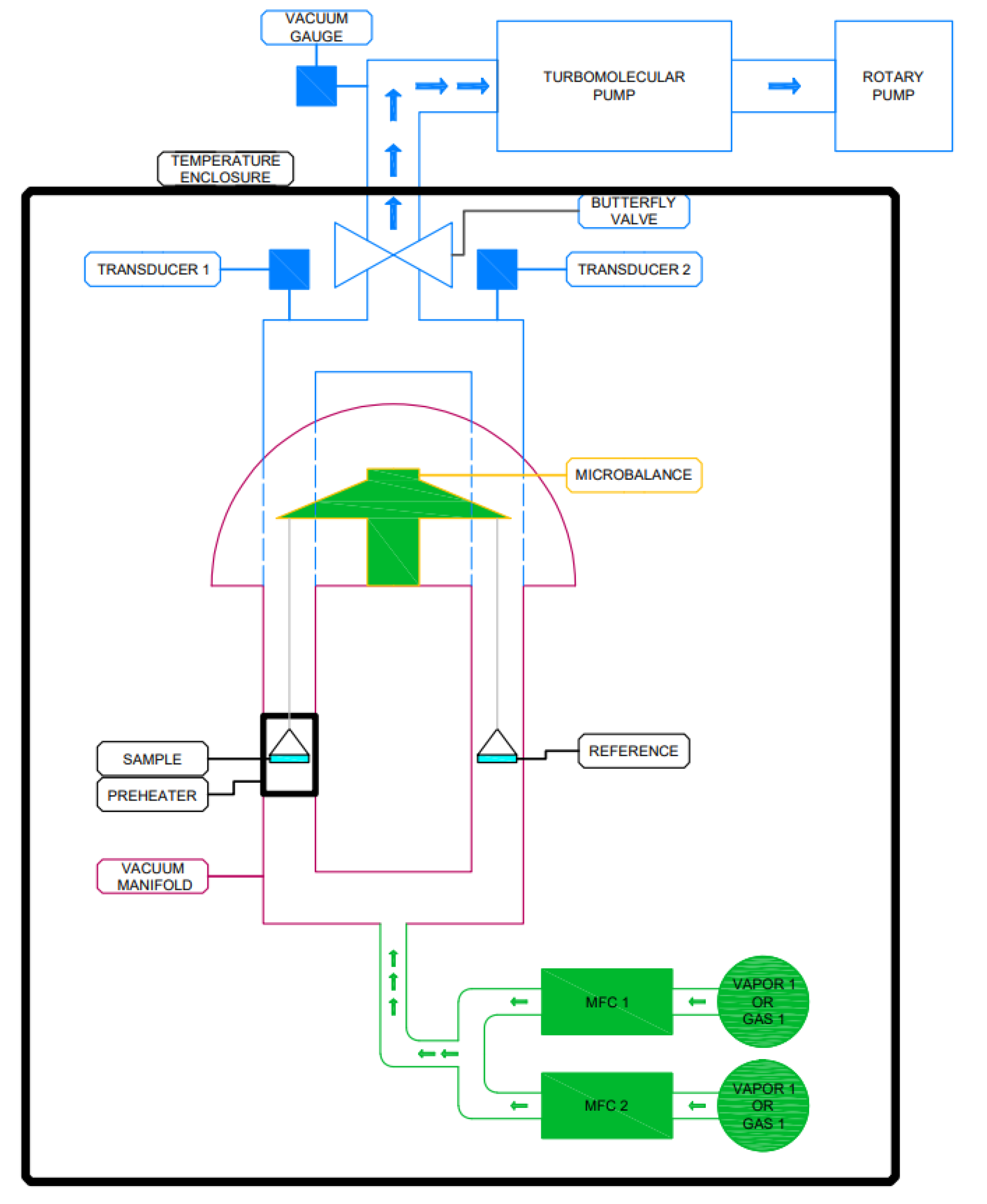
2.5. Water Adsorption Isotherm Determination

The amount of adsorbed water, so-called water uptake was measured using a gravimetric method in a DVS vacuum-surface measurement system presented in Figure 1. It is able to perform multi-component experiments using vapor and/or gas sorbate molecules with the in situ samples, degassing up to 400 °C and high vacuum [16]. This device is used to analyse the performance of porous materials, such as zeolites, porous polymers, composites, aluminophosphates (AlPOs) and silica aluminophosphates (SAPOs), silica gels, activated carbons and metal organic frameworks (MOFs) [16].
About 25 to 30 mg of the sample was analysed during the sorption capacity tests. In this study, the adsorption and desorption processes were analysed in the water vapor P/P0 range from 0 up to 90%. Five process temperatures were selected in this study: 25, 35, 45, 55 and 65 °C; relative pressure step (P/P0) was set to 10%; and time duration for each step was 20 min. The activation temperature of 170 °C was set for 90 min to dry and degas the analysed sample prior to the experiment; the incubator temperature (same as system temperature) and vapor flow rate were 25/65 °C and 50 cm, respectively.

3. Results and Discussion

The results of the performed experiments are presented and discussed in detail in this section. Adsorbents were compared according to their thermal and sorption properties. An additional comparison with previously published studies was performed.

3.1. Sample Characterization—Surface Area Analysis

Low-temperature gas adsorption results obtained from the studied samples allow for the determination the porosity of the samples (Figure 2). The results for the silica gel sample confirmed the mesoporous nature of the material with the highest adsorption capacity up to 0.4 P/P0, a specific surface area for this sample was 613 m2/g, and a total porous volume of 0.314 cm3/g. For the synthesized Na-A zeolite (12 h), the observed isotherm demonstrated lower adsorption capacity than expected for pure NaA, and the obtained specific surface area was only 45 m2/g. The specific surface area for commercial A-type zeolite, as noted in the literature, is around 850 m2/g [11], suggesting that the synthesized sample has a lower than expected share of zeolites in its structure. Thus, this result indicates that the conversion of fly ash to zeolite was very low. From XRD analysis, it has also been found that the desired zeolite was formed along with additional non-porous crystalline phases. These phases can block void spaces. Additionally, there are present amorphous phases which are apparently nonporous. This resulted in a lower specific area. Additionally, it has been found that the total porous volume is 0.109 cm3/g for the Na-A zeolite (12 h). The synthesis for 24 h resulted in a sample with better adsorption properties. The obtained specific surface area of the Na-A zeolite (24 h) is 185 m2/g, which is 78% lower compared to commercial A zeolite, suggesting that the synthesized sample has a smaller share of zeolite but is also significantly better that the sample obtained within a 12-h synthesis. Similar to the previous case, phase analysis shows that the desired zeolite was formed along with some nonporous crystalline phases, resulting in a lower specific surface area. The total porous volume of this sample was 0.171 cm3/g.
For both synthesized 13X zeolite and fly ash, which was the raw material for zeolite synthesis, the obtained specific surface area was almost negligible. This suggests that these are almost nonporous materials. However, phase analysis results showed that desired zeolite was formed. Based on phase analysis and surface area analysis it can be seen that only a very small portion was converted to zeolite, and the sample contains a significant amount of non-porous amorphous mass.

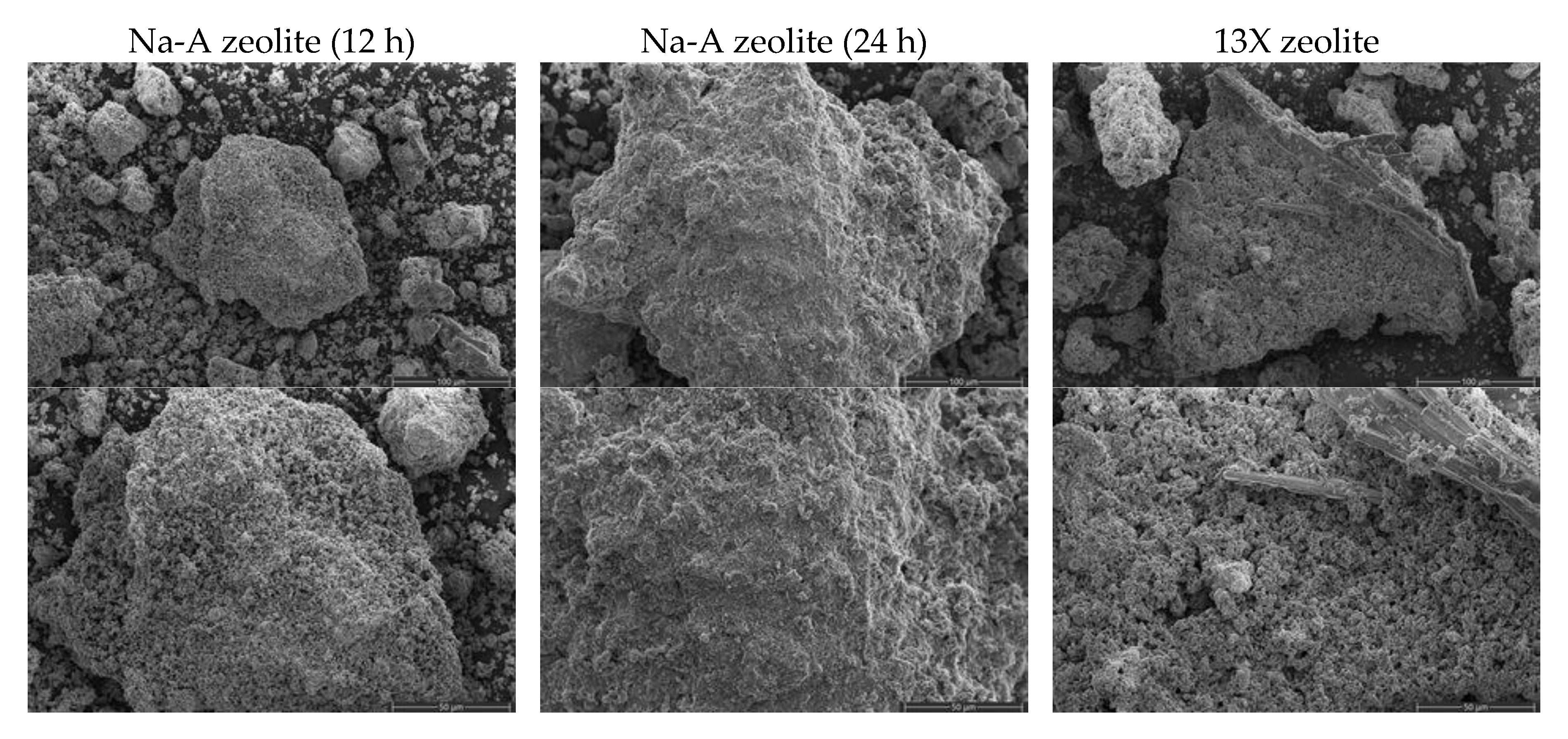
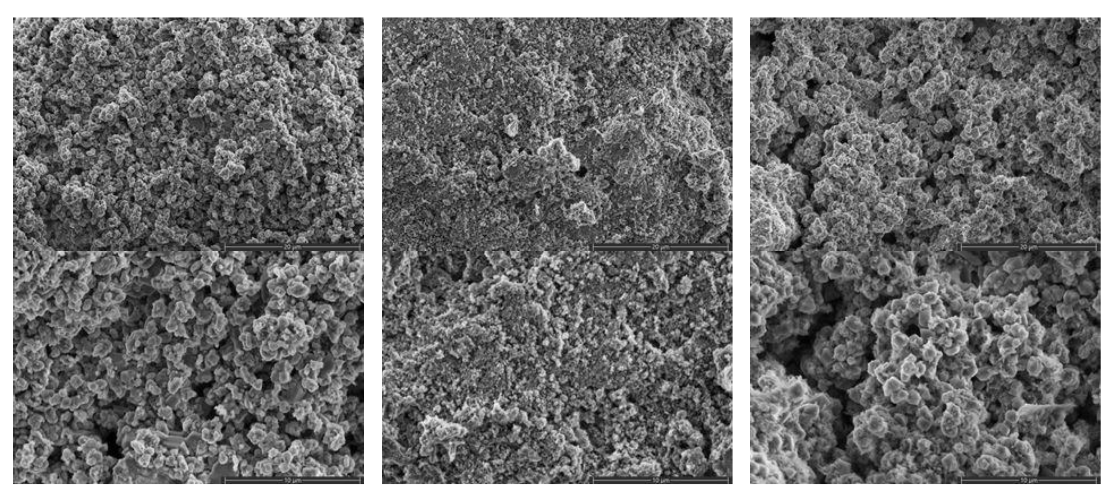
3.2. Sample Characterization—Morphology Analysis and Semi-Quantitative Analysis of Synthesised Zeolites Using Scanning Electron Microscopy with Energy Dispersive Spectroscopy (SEM–EDS)

The structural and morphological analysis of obtained zeolites was performed and the images are presented in Figure 3. The obtained materials are composed of irregular particles of different sizes and shapes. The microscopic photographs enable the analysis of the crystalline structure of obtained zeolites. In the case of Na-A zeolite (12 h) and 13X zeolite synthesized from fly ash, a well-developed, regular structure, characteristic for zeolites was observed, whereas in the case of the Na-A zeolite (24 h) sample, the structure was more irregular and crystals were present only locally. All samples present a mesoporous structure with a possible presence of micropores.
The energy dispersive spectroscopy (EDS) technique is generally used for the qualitative analysis of materials, but in this study semi-quantitative results for major components was provided to define the Si/Al ratio for the synthesised materials. The results are presented in Table 1. The type of zeolites depend on the content of SiO2 (the molar ratio of Si/Al). The ratio of Si/Al determines the properties of zeolite. Low-silica zeolites are characterized by a higher acid proofness, noticeable stability at higher temperatures and hydrophilicity. On the other hand, high-silica zeolites are more hydrophobic and have high ions exchange features.
The highest molar Si/Al ratio was obtained for 13X zeolites, treated with HCl before crystallization to minimize Fe and Al content. A similar Si/Al ratio was achieved for Na-A zeolites whose crystallization time was different and does not influence the relationship between silicon and aluminium content.

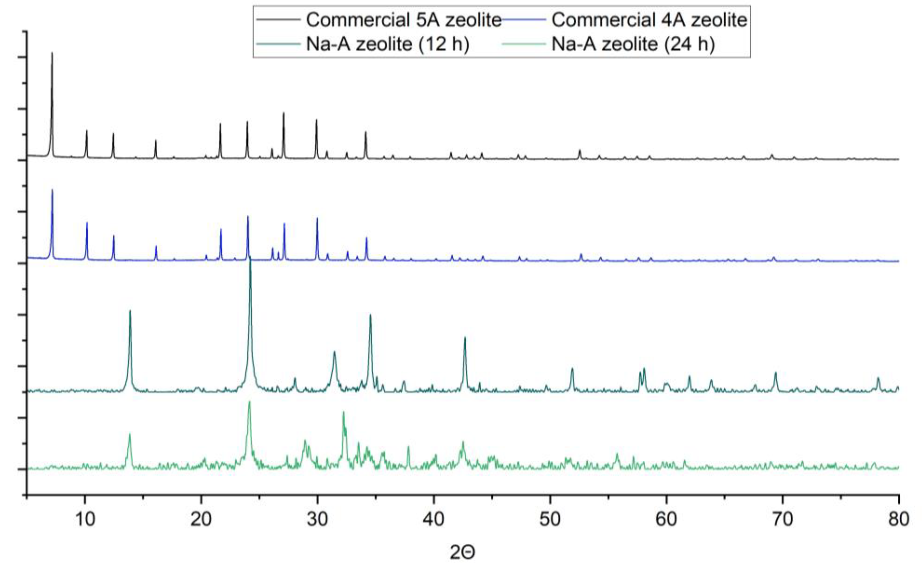
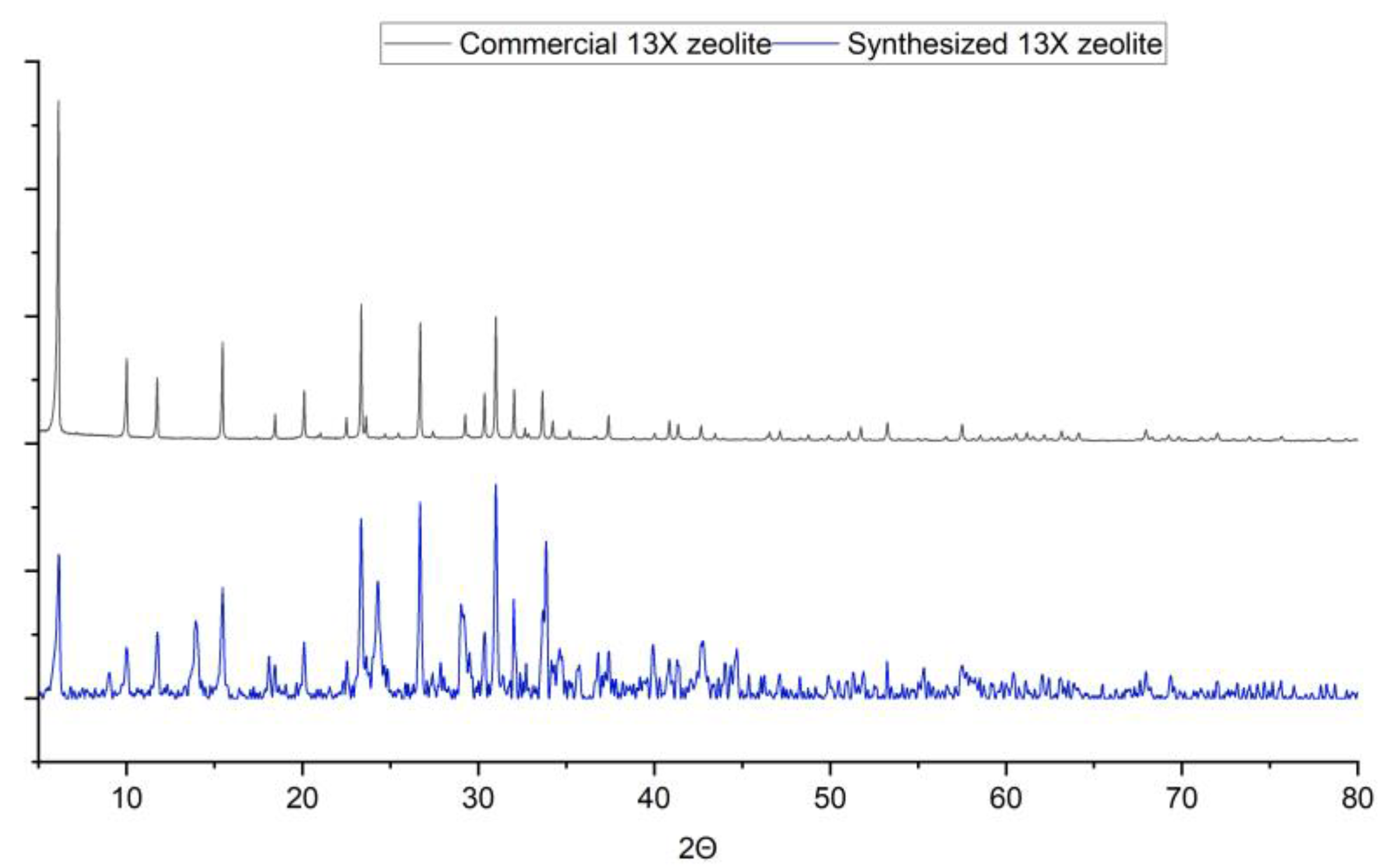
3.3. Sample Characterization—Phase Analysis

The X-ray diffractograms of two commercial zeolites, 4A and 5A, are presented and compared with the obtained Na-A zeolites in Figure 4. For commercial 4A zeolite, numerous peaks were noted at 7.2, 10.18, 12.48, 16.12, 21.7, 24.02, 27.14, 29.98, 32.6 and 34.22, in the case of the second commercial zeolite (5A), similar peaks were noted. For synthesized Na-A zeolite (12 h), reflections were noted at 13.0, 24.22, 28.06, 31.46, 34.56, 42.7, 51.9, 58.08, 60.12, 61.96, 63.88, 69.38 and 78.2. The similarity between commercial and synthesized Na-A zeolite in the case of phase analysis was achieved only to a minor extent. Other peaks were noted as well, which indicate the presence of other crystalline phases. Other detected phases are potassium aluminium silicon oxide and sodium calcium aluminium silicate hydrate. Zeolite constitutes 66% of the total crystalline phase and the rest of the crystalline phases constitute 34%.
For the synthesized Na-A zeolite (24 h), several reflections were noted at 13.88, 24.16, 28.94, 32.24, 32.5, 37.82, 40.2, 42.54 and 55.78 and a higher amorphous phase content was also noted in this case. Other peaks were observed as well, which indicate the presence of other crystalline phases. Other detected phases are calcium hydroxide and potassium hydrogen carbonate. Zeolite constitutes 47% of the total crystalline phase and the rest of the crystalline phases constitute 53%. Both Na-A synthesized zeolites were characterised by a very similar composition.
The X-ray diffractograms of 13X commercial zeolite is presented and compared with obtained 13X zeolite in Figure 5. For commercial zeolite, peaks are present at 6.13, 10.02, 11.75, 15.45, 18.46, 20.12, 23.34, 26.70, 30.94, 31, 32 and 33.65. For synthesised 13X zeolite, reflections were noted at 6.16, 10, 11.78, 13.92, 15.46, 18.08, 20.08, 23.34, 24.3, 26.7, 29, 31, 32 and 33.86, which almost superimposes on the reflection peaks of commercial zeolite. Some additional peaks are present as well, which indicate the presence of other crystalline phases as well. Other detected phases are sodium hydrogen carbonate, CaCO3 and sodium aluminium silicon carbonate oxide. Zeolite constitutes 60% of the total crystalline phase and the rest of the crystalline phases constitutes 40%.

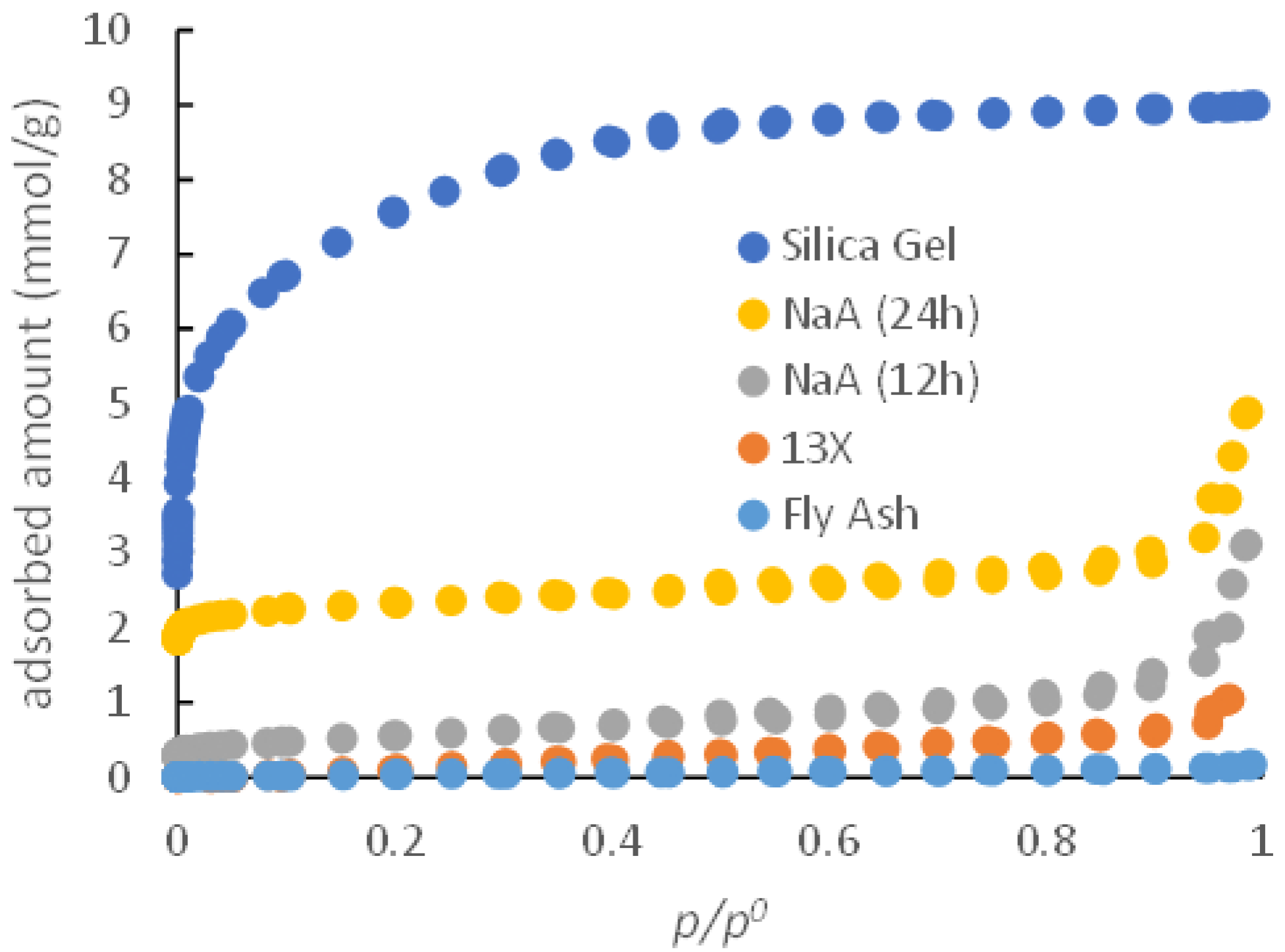
3.4. Adsorption Isotherm and Potential Use in Adsorption Chiller
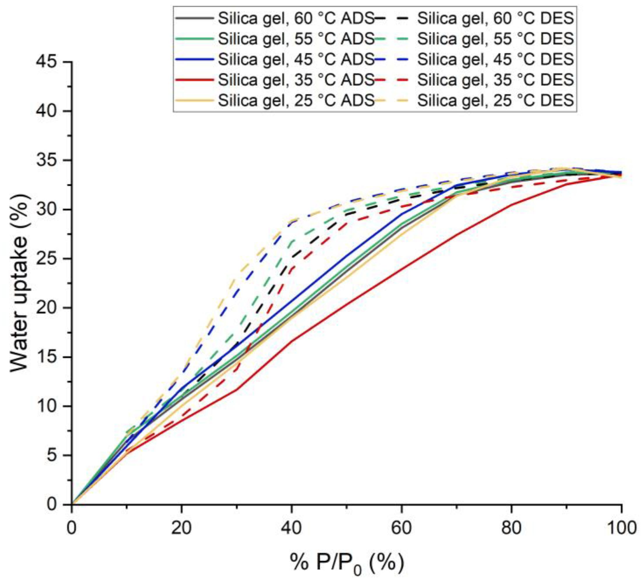
The water intake was tested in the temperature range of 25–65 °C, the sorption isotherms are shown in Figure 6 for silica gel as a reference material and for synthesized zeolites (Figure 7, Figure 8 and Figure 9).

3.4.1. Silica Gel

Silica gel adsorbed 33.25% water vapor for P/P0 = 100% at 25 °C and 33.69% for P/P0 = 100% at 65 °C. This amount was adsorbed within 25 min. Within this time, silica gel almost reached its highest adsorption capacity. However, adsorption kinetics suggest that it could have adsorbed and desorbed (for lower P/P0) more if the time for each step had been increased. This would result in smaller hysteresis.
From the shape of the isotherm in Figure 5, it can be concluded that it is a type IV isotherm [17,18]. It is a multilayer adsorption process. It also has a significant hysteresis issue. The observed type H2(b) hysteresis usually results from pore neck blocking [18]. The hysteresis loop becomes smaller with increased temperatures.

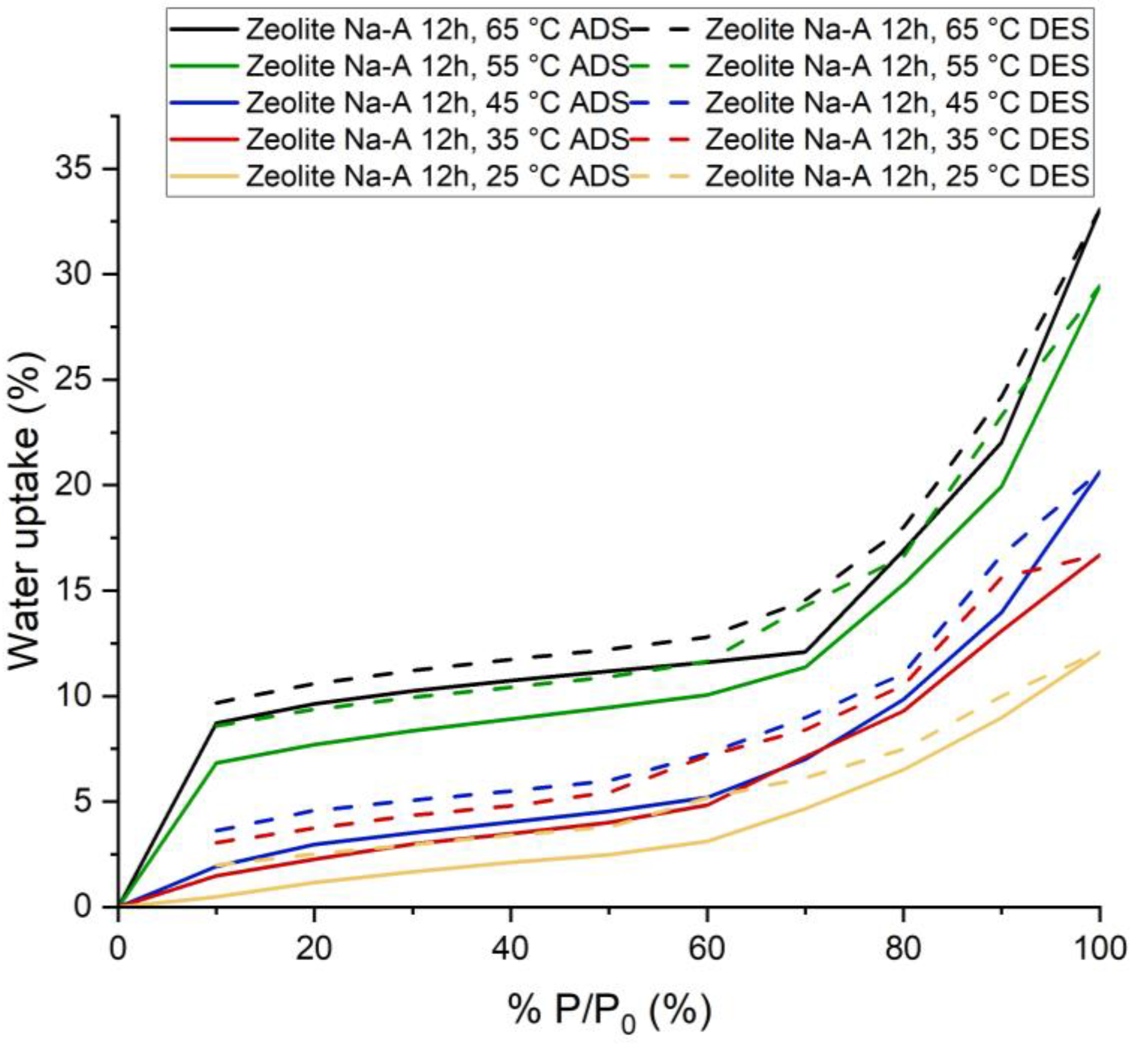
3.4.2. Synthesized Na-A Zeolite (12 h)

Synthesized Na-A zeolite (12 h) adsorbed 12.09% water vapor at P/P0 = 100% and 25 °C and 33.07% at P/P0 = 100% and 65 °C. This amount of water was adsorbed within 60 min. The adsorption kinetics showed that for higher pressures, if the time of adsorption had been increased, this sample would have been able to adsorb more water vapor. However, for lower P/P0 (which is actually the working condition for adsorption chillers [19,20,21,22,23,24,25,26,27,28,29,30,31]), equilibrium was almost reached in less than 20 min.
The shape of the isotherm is type IV. The flat region indicates monolayer adsorption, followed by a rise which indicates multilayer adsorption. It is characteristic of mesoporous materials [17,18], but this does not seem to be the case here. The adsorption in the lower pressure region occurred due to the presence of zeolite. The increase in adsorption in higher pressure regions occurred due to capillary condensation in intergranular voids. Additionally, hydration probably played a part. It also has significant hysteresis.
The usual shape for commercial Na-A zeolite is Type I [32] and the adsorption capacity is also very high at lower P/P0 compared to synthesized Na-A zeolite (12 h). For commercial Na-A zeolite and synthesized Na-A zeolite (12 h), the adsorption capacity at 25 °C and P/P0 = 20% is 28% and 1.66%, respectively. XRD and surface area analysis suggested that other non-porous crystalline phases and amorphous phases are present, which explains the reason for having different types of isotherms and lower adsorption capacity.
Potential Use in Adsorption Chillers: The performance of the adsorption refrigeration system is determined by COP and P. These two parameters largely depend on the adsorbent–adsorbate working pair performance, such as how quickly the adsorbent can adsorb and desorb the refrigerant and what amount of adsorbate will be taken by the absorbent under given working conditions (pressure and temperature) [1].
As explained before, for this sample, the adsorption took 60 min. However, based on adsorption kinetics for Na-A zeolite (12 h), it actually took less than 20 min to reach equilibrium (almost) at lower P/P0, whereas for silica gel it was around 25 min. This implies that the sample will have a better adsorption refrigeration cycle time compared to silica gel.
To determine the potential of the Na-A zeolite (12 h) as an adsorbent in the sorption chiller in working pair with water, conditions and performance of adsorption chillers were taken from previously published papers [19,20,21,22,23,24,25,26,27,28,29,30,31]. For those chillers, during adsorption, the pressure of the adsorbent bed is always lower, usually above 15% of the saturation pressure, and can sometimes be as high as 45% [22,23,24,25,26,27,28,29,30,31,32]. The temperature usually ranges between 25–40 °C [19,20,21,22,23,24,25,26,27,28,29,30,31]. During the desorption of the refrigerant the temperature varies significantly (usually more than 65 °C and can be as high as 120 °C for solar energy as heat resource), whereas the pressure is usually less than 5% of the saturation pressure of the respective temperature and can sometimes be more than 10% as well [19,20,21,22,23,24,25,26,27,28,29,30,31]. Based on these research works, two different working conditions have been considered.
First, for adsorption, 25 °C temperature and 30% of saturation pressure (for water at 25 °C) were considered. In these conditions, silica gel (14.37%) adsorbed much more water vapor than Na-A zeolite (12 h) (1.66%). For desorption, if the temperature 65 °C and the pressure of 10% of the saturation pressure were considered, the water uptake at this condition was 9.68% and 6.99% for synthesized zeolite and silica gel, respectively. Therefore, under these conditions, the average adsorption capacity in the case of our sample and silica gel are 0% and 7.38%, respectively. So, produced zeolite cannot produce any cold energy and replace silica gel as an adsorbent for the adsorption chiller.
Second, for adsorption, 25 °C temperature and 20% of saturation pressure (for water at 25 °C) were considered. In these conditions, silica gel (10.02%) adsorbed much more water vapor than synthesized zeolite (1.16%). For desorption, at a temperature of 65 °C and a pressure of 10% of the saturation pressure, the adsorbed amount at this condition is 9.68% and 6.99%. Therefore, under these conditions, the amount of water refrigerant available for evaporation at the evaporator in the case of the Na-A zeolite (12 h) and silica gel would be 0% and 3.03%, respectively. Thus, our sample cannot produce any cold energy and replace silica gel as an adsorbent for the sorption chiller.

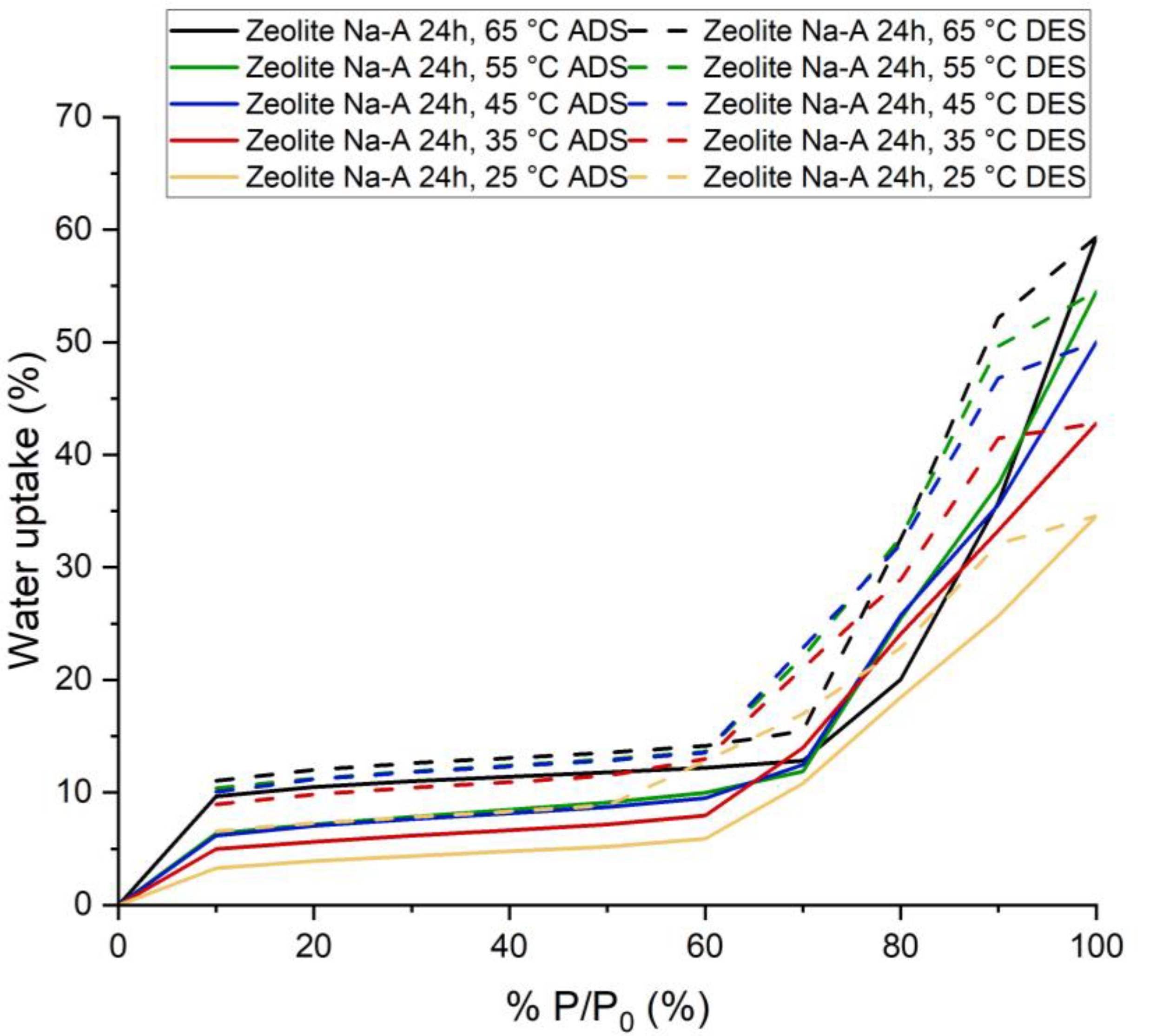
3.4.3. Synthesized Na-A Zeolite (24 h)

Synthesized Na-A zeolite (24 h) adsorbed 34.57% water vapor for P/P0 = 100% at 25 °C and 59.33% for P/P0 = 100% at 65 °C (Figure 7). This amount of adsorption was achieved in 60 min. The adsorption kinetics suggests that for higher pressure if we increased the duration of adsorption, this sample would have been able to adsorb a little more water vapor. However, for lower P/P0 (which is actually the working condition for adsorption chiller [19,20,21,22,23,24,25,26,27,28,29,30,31]), equilibrium was almost reached in less than 20 min.
The shape of the isotherm is a type IV isotherm. The flat region indicates monolayer adsorption, followed by a rise which indicates multilayer adsorption [17,18]. The adsorption in the lower pressure region occurred due to the presence of zeolite. The increase in adsorption in the region of higher pressure occurred due to capillary condensation in intergranular voids. It seems KHCO3 also contributed, while hydration probably also played a part. It also has a significant hysteresis.
The usual shape for commercial Na-A zeolite is Type I and the adsorption capacity is also very high at lower P/P0 compared to synthesized Na-A zeolite (24 h). For commercial Na-A zeolite and synthesized Na-A zeolite (24 h), the adsorption capacity at 25 °C and P/P0 = 20% is 28% and 3.90%, respectively. The reasons again here are the presence of non-porous crystalline phases and amorphous phases.
Potential Use in Adsorption Chillers: For this sample, the whole adsorption cycle took 60 min. However, the adsorption kinetics of the sample showed that it actually took less than 20 min to reach equilibrium at lower P/P0, whereas for silica gel it was around 25 min. This implies that the sample has better adsorption refrigeration cycle times compared to silica gel.
Similar to the previous cases, two working scenarios were taken into consideration.
First, for adsorption, 25 °C temperature and 30% of saturation pressure (for water at 25 °C) were considered. In these conditions, silica gel (14.37%) adsorbed much more water vapor than the Na-A zeolite (24 h) sample (4.35%). For desorption, considering the temperature of 65 °C and pressure of 10% of the saturation pressure, the adsorption amounts at these conditions were 11.03% and 6.99% for synthesized zeolite and silica gel, respectively. Therefore, under these conditions, the average adsorption capacity in the case of our sample and silica gel are 0% and 7.38%, respectively. Thus, synthesized zeolite cannot produce any cold energy and replace silica gel as an adsorbent for the adsorption chiller.
Second, for adsorption, the temperature of 25 °C and 20% of saturation pressure (for water at 25 °C) were considered. In these conditions, silica gel (10.02%) adsorbed much more water vapor than the zeolite sample (3.90%) at this temperature and pressure. For desorption, if we consider the temperature is 65 °C and the pressure is 10% of the saturation pressure, the adsorption amount under these conditions was 11.03% and 6.99%. Therefore, under these conditions, the possible amount of water refrigerant available for vaporization at the evaporator in the case of our sample and silica gel should be 0% and 3.03%, respectively. Additionally, in this case, the synthesized sample cannot produce any cold energy and replace silica gel as an adsorbent for the adsorption chiller.

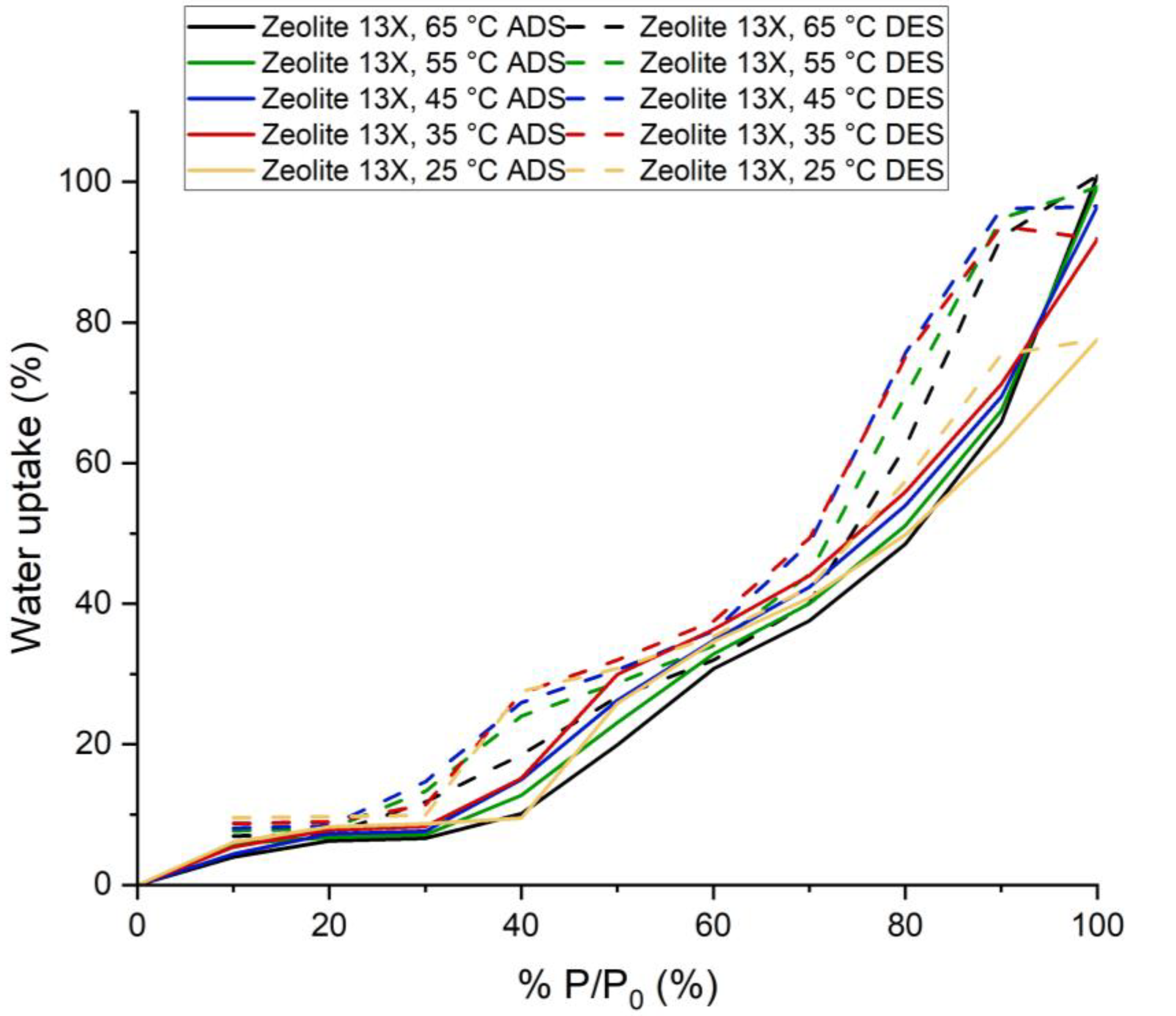
3.4.4. Synthesized 13X Zeolite

Synthesized 13-X zeolite (12 h) adsorbed 77.64% water vapor for P/P0 = 100% at 25 °C and 100.9% for P/P0 = 100% at 65 °C. This amount of adsorption was achieved in 60 min. The adsorption kinetics suggests that for higher pressure by increasing the adsorption time, this sample would have been able to adsorb a little more water vapor. However, for lower P/P0 (which is actually the working condition for adsorption chiller [19,20,21,22,23,24,25,26,27,28,29,30,31]), equilibrium was almost reached in less than 25 min.
The shape of the isotherm for this sample is a type VI isotherm. Similarly to the previous case, the flat region indicates monolayer adsorption, followed by a rise in two different steps. The adsorption in the lower pressure region occurred due to the presence of synthesized zeolite. The increase in adsorption in the region of higher pressure occurred due to capillary condensation in intergranular voids. It seems that NaHCO3 also contributed, while hydration probably played a part.
The usual shape for commercial Na-X zeolite is Type I [32] and the adsorption capacity is also very high at lower P/P0 compared to the synthesized zeolite. For commercial zeolite and synthesized zeolite, the adsorption capacity at 25 °C and P/P0 = 20% is 34% and 8.27%, respectively. XRD and surface analysis suggests that there are other non-porous crystalline phases and amorphous phases present, which explains the reason for having a different type of isotherm and lower adsorption capacity. Additionally, we can say that only a small amount of raw material is converted to zeolite.
Potential Use in Adsorption Chillers: As presented before, for this sample, the adsorption took 60 min. However, according to the adsorption kinetics, it can be concluded that it actually took less than 25 min to reach equilibrium at lower P/P0. In fact, for higher temperatures, it was less than 20 min. For silica gel, it was around 25 min. This implies that for this sample adsorption refrigeration cycle, the time will be similar or less when compared to silica gel.
At 25 °C and 30% of saturation pressure (for water at 25 °C) silica gel (14.37%) adsorbed much more water vapor than the synthesized 13X zeolite (8.73%). For desorption, taking into consideration a temperature of 65 °C and a pressure of 10% of the saturation pressure, the adsorbed amount of water vapor under these conditions was 7% and 6.99% for zeolite and silica gel, respectively. Therefore, under these conditions, the average adsorption capacity for 13X zeolite and silica gel would be 1.73% and 7.38%, respectively. The zeolite–water vapor working pair produces cold energy, but it cannot replace silica gel as an adsorbent for the adsorption chiller. In these working conditions, silica gel has the potential to produce almost 4.3 times more cold energy than our samples.
Taking into consideration the decrease of pressure to 20% of saturation pressure (for water at 25 °C), silica gel (10.02%) adsorbed much more water vapor than analysed zeolite (8.27%). For desorption, if a temperature of 65 °C and a pressure of 10% of the saturation pressure were considered, the adsorption amount would be 7% and 6.99%. So, under these conditions, the amount of water refrigerant available for vaporization at the evaporator for 13X zeolite and silica gel would be 1.27% and 3.03%, respectively. Similarly to the previous case, zeolite will be able to produce cold energy, but it cannot replace silica gel as an adsorbent for the adsorption chiller. For such working conditions, silica gel has the potential to produce almost 2.4 times more cold energy than synthesized zeolite.

4. Conclusions

The results of the phase analysis showed that the targeted compound, such as Na-A zeolite and 13X zeolite, were produced successfully from the fly ash using the applied hydrothermal treatment. However, the presence of other non-porous crystalline phases and amorphous phases was evident as well. In the respective samples, Na-A zeolite (12 h), Na-A zeolite (24 h) and 13X zeolite constitute 66%, 47% and 60% of the total crystalline phase. Through the impregnation of K2CO3 other phases were developed. Additionally, the conversion percentage was low and for 13X zeolite it was very low. However, the applied treatments increased the water adsorption capacity of the raw material.
The morphology of the samples analysed using a scanning electron microscope showed that a well-developed crystalline structure was observed in the case of Na-A (12 h) and 13X zeolites. A high-silicone 13X zeolite was obtained through the treatment of a sample with HCl prior crystallization.
Considering the standard operating condition of an adsorption chiller, it has been found that synthesized Na-A zeolite samples cannot produce any cold energy, whereas the synthesized 13X zeolite has the potential to create cold energy. However, it cannot replace silica gel (which is used commercially) as an adsorbent in an adsorption chiller. The performance of zeolite is 2–4 times lower when compared with silica gel.
Different approaches can be used to obtain better zeolite synthesis from fly ash in order to impregnate zeolite with K2CO3 without forming any other type of compound and to improve the adsorption and desorption performances of these synthesized materials so that they are suitable for adsorption chillers. Additionally, they could be used for other purposes, such as water desiccant and CO2 capture. However, in order to test feasibility, these possibilities will require further study.

Author Contributions

Conceptualization, T.H., K.S. and M.L.P.; methodology, W.K. and M.S.; validation, A.M.-M. and K.S.; formal analysis, A.M.-M.; investigation, T.H. and A.M.-M.; resources, K.S., M.L.P. and Ł.M.; data curation, W.K. and M.S.; writing—original draft preparation, T.H.; writing—review and editing, A.M.-M., K.S. and M.L.P.; visualization, A.M.-M.; supervision, K.S., M.L.P. and Ł.M.; project administration, K.S.; funding acquisition, A.M.-M., K.S., M.L.P. and Ł.M. All authors have read and agreed to the published version of the manuscript.

Funding

This research was funded by Ministry of Science and Higher Education, Poland, grant AGH no 16.16.210.476, and partly supported by the program “Excellence initiative—research university” for the AGH University of Science and Technology. A.M.-M. is supported by the Foundation for Polish Science (FNP).

Institutional Review Board Statement

Not applicable.

Informed Consent Statement

Not applicable.

Conflicts of Interest

The authors declare no conflict of interest.

References

  1. Wang, R.; Wang, L.; Wu, J. Adsorption Refrigeration Technology: Theory and Application, 1st ed.; Wiley: Wiley, NJ, USA, 2014. [Google Scholar] [CrossRef]
  2. IEA. Cooling. Available online: https://www.iea.org/reports/cooling (accessed on 23 January 2021).
  3. IEA. The Future of Cooling. Available online: https://www.iea.org/reports/the-future-of-cooling (accessed on 23 January 2021).
  4. IEA. Explore Energy Data by Category, Indicator, Country or Region. Available online: https://www.iea.org/data-and-statistics?country=WORLD&fuel=Electricity%20and%20heat&indicator=ElecGenByFuel (accessed on 23 January 2021).
  5. Wolak, E.; Kraszewski, S. An overview of adsorptive processes in refrigeration systems. In Proceedings of the 1st International Conference on the Sustainable Energy and Environment Development (SEED), Krakow, Poland, 17–19 May 2016; Volume 10, p. 00104. [Google Scholar] [CrossRef] [Green Version]
  6. Lenntech. Zeolite Structure. Available online: https://www.lenntech.pl/zeolites-structure-types.htm#:~:text=Zeolites%20are%20three%2Ddimensional%2C%20microporous,other%20through%20shared%20oxygen% (accessed on 23 January 2021).
  7. Moshoeshoe, M.; Tabbiruka, M.S.N.; Obuseng, V. A Review of the Chemistry, Structure, Properties and Applications of Zeolites. Am. J. Mater. Sci. 2017, 7, 196–221. [Google Scholar] [CrossRef]
  8. Julbe, A.; Drobek, M. Zeolite A Type. In Encyclopedia of Membranes; Drioli, E., Giorno, L., Eds.; Springer: Berlin/Heidelberg, Germany, 2016. [Google Scholar] [CrossRef]
  9. Ríos, C.A.; Williams, C.D.; Castellanos, O.M. Crystallization of low silica Na-A and Na-X zeolites from transformation of kaolin and obsidian by alkaline fusion. Ing. Compet. 2012, 14, 9–22. [Google Scholar]
  10. Fruijtier-Pölloth, C. The safety of synthetic zeolites used in detergents. Arch. Toxicol. 2009, 83, 23–35. [Google Scholar] [CrossRef] [PubMed]
  11. Rahmati, M.; Modarress, H. The effects of structural parameters of zeolite on the adsorption of hydrogen: A molecular simulation study. Mol. Simul. 2012, 38, 1038–1047. [Google Scholar] [CrossRef]
  12. Julbe, A.; Drobek, M. Zeolite X: Type. In Encyclopedia of Membranes; Drioli, E., Giorno, L., Eds.; Springer: Berlin/Heidelberg, Germany, 2014. [Google Scholar] [CrossRef]
  13. Georgiev, D.; Bogdanov, B.; Markovska, I.; Hristov, Y. A Study on the Synthesis and Structure of Zeolite NaX. J. Chem. Technol. Metall. 2013, 48, 168–173. [Google Scholar]
  14. Ma, B.; Lothenbach, B. Synthesis, characterization, and thermodynamic study of selected Na-based zeolites. Cem. Concr. Res. 2020, 135, 106111. [Google Scholar] [CrossRef]
  15. Indira, V.; Abhitha, K. A review on recent developments in Zeolite A synthesis for improved carbon dioxide capture: Implications for the water-energy nexus. Energy Nexus 2022, 7, 100095. [Google Scholar] [CrossRef]
  16. DVS Vacuum-Surface Measurement System (Device Brochure). Available online: https://www.surfacemeasurementsystems.com/wpcontent/uploads/2017/08/DVS_Vacuum.pdf (accessed on 14 April 2021).
  17. Yahia, M.B.; Torkia, Y.B.; Knani, S.; Hachicha, M.A.; Khalfaoui, M.; Lamine, A.B. Models for Type VI Adsorption Isotherms from a Statistical Mechanical Formulation. Adsorpt. Sci. Technol. 2013, 31, 341–357. [Google Scholar] [CrossRef]
  18. Sotomayor, F.J.; Cychosz, K.A.; Thommes, M. Characterization of Micro/Mesoporous Materials by Physisorption: Concepts and Case Studies. Acc. Mater. Surf. Res. 2018, 3, 34–50. [Google Scholar]
  19. Ambarita, H.; Kawai, H. Experimental study on solar-powered adsorption refrigeration cycle with activated alumina and activated carbon as adsorbent. Case Stud. Therm. Eng. 2016, 7, 36–46. [Google Scholar] [CrossRef] [Green Version]
  20. Wang, X.; He, Z.; Chua, H.T. Performance simulation of multi-bed silica gel-water adsorption chillers. Int. J. Refrig. 2015, 52, 32–41. [Google Scholar] [CrossRef]
  21. Sayfikar, M.; Behbahani-nia, A. Study of the performance of a solar adsorption cooling system. Energy Equip. Syst. 2013, 1, 75–90. [Google Scholar] [CrossRef]
  22. Brites, G.; Costa, J.; Costa, V. Sustainable Refrigeration Based on The Solar Adsorption Cycle. Available online: https://inovenergy.inovcluster.pt/media/29412/SUSTAINABLE_REFRIGERATION_BASED_ON_THE_SOLAR_ADSORPTION_CYCLE.pdf (accessed on 14 April 2021).
  23. Uyun, A.S.; Akisawa, A.; Miyazaki, T.; Ueda, Y.; Kashiwagi, T. Numerical analysis of an advanced three-bed mass recovery adsorption refrigeration cycle. Appl. Therm. Eng. 2009, 29, 2876–2884. [Google Scholar] [CrossRef]
  24. Saha, B.B.; Koyama, S.; Lee, J.B.; Kuwahara, K.; Alam, K.C.A.; Hamamoto, Y.; Akiswa, A.; Kashiwagi, T. Performance evaluation of a low-temperature waste heat driven multi-bed adsorption chiller. Int. J. Multiph. Flow 2003, 29, 1249–1263. [Google Scholar] [CrossRef]
  25. Sharafian, A.; Mehr, S.M.N.; Huttema, W.; Bahrami, M. Effects of different adsorber bed designs on in-situ water uptake rate measurements of AQSOA FAM-Z02 for vehicle air conditioning applications. Appl. Therm. Eng. 2016, 98, 568–574. [Google Scholar] [CrossRef]
  26. Khanam, M.; Jribi, S.; Miyazaki, T.; Saha, B.B.; Koyama, S. Energy Analysis and Performance Evaluation of the Adsorption Refrigeration System. Energies 2018, 11, 1499. [Google Scholar] [CrossRef] [Green Version]
  27. Sitorus, T.B.; Napitupulu, F.H.; Ambarita, H. A Study on Adsorption Refrigerator Driven by Solar Collector Using Indonesian Activated Carbon. J. Eng. Technol. Sci. 2017, 49, 657–670. [Google Scholar] [CrossRef] [Green Version]
  28. Sharafian, A.; Dan, P.C.; Huttema, W.; Bahrami, M. Performance analysis of a novel expansion valve and control valves designed for a waste heat-driven two-adsorber bed adsorption cooling system. Appl. Therm. Eng. 2016, 100, 1119–1129. [Google Scholar] [CrossRef]
  29. Myat, A.; Choon, N.K.; Thu, K.; Kim, Y.D. Experimental investigation on the optimal performance of Zeolite–water adsorption chiller. Appl. Energy 2013, 102, 582–590. [Google Scholar] [CrossRef]
  30. Schawe, D. Theoretical and Experimental Investigations of an Adsorption Heat Pump with Heat Transfer between Two Adsorbers. Ph.D. Dissertation, Process and Biotechnology, Faculty of Energy, University of Stuttgart, Stuttgart, Germany, 2001. [Google Scholar] [CrossRef]
  31. Trindade, M.V. Modelling and Optimization of an Adsorption Cooling System for Automotive Applications. Ph.D. Dissertation, Doctoral Program of Energy Technology, Universidad Politécnica De Valencia, Valencia, Spain, 2015. Available online: https://riunet.upv.es/handle/10251/54120 (accessed on 9 September 2022).
  32. Sharma, P.; Song, J.S.; Han, M.; Cho, C.H. GIS-NaP1 zeolite microspheres as potential water adsorption material: Influence of initial silica concentration on adsorptive and physical/topological properties. Sci. Rep. 2016, 6, 22734. [Google Scholar] [CrossRef] [PubMed]
Figure 1. DVS Vacuum Surface Measurement System.
Energies 15 07444 g001
Figure 2. Adsorption Isotherm for Different Samples (at −196 °C).
Energies 15 07444 g002
Figure 3. Morphology of synthesized zeolites.
Energies 15 07444 g003aEnergies 15 07444 g003b
Figure 4. Phase Analisis Result Comparison, Commercial 4A Zeolite, Commercial 5A Zeolite, Synthesized Na-A Zeolite and Synthesized Na-A Zeolite (24 h).
Energies 15 07444 g004
Figure 5. Phase Analisis Result Comparison: Commercial 13X Zeolite and Synthesized 13X Zeolite.
Energies 15 07444 g005
Figure 6. Adsorption and Desorption Isotherms for Silica Gel (at five process temperatures 25, 35, 45, 55 and 60 °C.
Energies 15 07444 g006
Figure 7. Adsorption and Desorption Isotherms for Synthesized Na-A Zeolite (12 h) at five process temperatures: 25, 35, 45, 55 and 65 °C.
Energies 15 07444 g007
Figure 8. Adsorption and Desorption Isotherms for Synthesized Na-A Zeolite (24 h) at five process temperatures: 25, 35, 45, 55 and 65 °C.
Energies 15 07444 g008
Figure 9. Adsorption and Desorption Isotherms for Synthesized 13X at five process temperatures: 25, 35, 45, 55 and 65 °C.
Energies 15 07444 g009
Table 1. Semi-quantitative analysis of selected components of produced zeolites.
Na-A Zeolite (12 h), mol%Na-A Zeolite (24 h), mol%13X Zeolite, mol%
Na30.622.122.7
Si28.419.537.8
Al24.316.121.7
Si/Al1.171.211.74
Publisher’s Note: MDPI stays neutral with regard to jurisdictional claims in published maps and institutional affiliations.

