Abstract
Heat transfer analysis of the pulsatile flow of a hybrid nanofluid through a constricted channel under the impact of a magnetic field and thermal radiation is presented. Hybrid nanofluids form a new class of nanofluids, distinguished by the thermal properties and functional utilities for improving the heat transfer rate. The behaviors of a water-based copper nanofluid and water-based copper plus a single-wall carbon nanotube, i.e., (/water), hybrid nanofluid over each of velocity, wall shear stress, and temperature profiles, are visualized graphically. The time-dependent governing equations of the incompressible fluid flow are transformed to the vorticity-stream function formulation and solved numerically using the finite difference method. The laminar flow simulations are carried out in 2D for simplicity as the flow profiles are assumed to vary only in the 2D plane represented by the 2D Cartesian geometry. The streamlines and vorticity contours are also shown to demonstrate the flow behviour along the channel. For comparison of the flow characteristics and heat transfer rate, the impacts of variations in Hartmann number, Strouhal number, Prandtl number, and the thermal radiation parameter are analyzed. The effects of the emerging parameters on the skin friction coefficient and Nusselt number are also examined. The hybrid nanofluid is demonstrated to have better thermal characteristics than the traditional one.
1. Introduction
Blood flow (pulsatile flow) in the arteries exhibits a periodically echoing time scale that affects the flow-induced mass transfer. This makes the modeling of the physiological processes challenging because the time scales of the characteristics are larger than the pulse period. To address the challenge, researchers look at performing time-averaging over the period to reduce the flow variations within the time period so as to capture a characteristic flow profile. In addition, for discussing the blood flow characteristics in arteries, researchers used constricted channels instead of straight channels because of their geometrical advantages. The phenomena of blood flow through arteries have been associated as an essential factor in hemostasis. For example, many events such as atherogenesis, platelet adhesion, thrombosis, and red blood cell lysis have been connected to various hemodynamic factors.
A nanofluid (NF) is formed by an engineered suspension of nanoparticles (NPs) of a highly conducting substance (such as copper, aluminum, carbon nanotubes, etc.) in a base fluid such as water. The nanofluids are used extensively for their higher thermal conductivity than the base fluids alone. NPs can be categorized into various types by scale, morphology, and physical and chemical properties. As explained by Saidur et al. [1], NFs are in use as heat transfer fluids, biological fluids, pharmaceutical fluids, environmental fluids, etc. Researchers have been analyzing the characteristics of NFs in various applications both experimentally and numerically for even further enhancement in thermal conductivity. Choi [2] was the first one to study the enhancement of thermal conductivity in NFs. Buongiorno [3] simplified the mathematical formulation of the NFs. He described the basic mechanics that lead to the enhancement of the thermal characteristics. This analysis was extended by Kuznetsov and Nield [4] for the boundary layer model of free convective NF flows. Wong and Leon [5] researched NFs as suspensions of NPs in fluids showing substantial improvement in their properties at moderate NP concentrations. Akbar [6] examined the peristaltic flow of incompressible viscous fluid containing metallic NPs in an irregular duct. The combined impact of Lorentz and Kelvin forces in two dimensional /water NF flow (NFF) was studied by Sheikoleslami et al. [7]. Hayat et al. [8] studied the structures of chemical species on NFF impacted by the rotation of a disc. They reported that the amount of surface shear stress rises with the solid volume fraction of NPs. Paul and Mandal [9] investigated the stretched flow of radiative MHD micropolar NF. Alizadeh et al. [10] studied thermally developed MHD micropolar NFF. They reported that the Nusselt number rises with radiation strength and volume fraction. Dib et al. [11], reported that the presence of NPs enhances heat transfer for their problem of setting the flow between two plates. Cacua et al. [12], demonstrated that NPs improve the thermal characteristics. In practice, NFs might have severe stability issues due to the agglomeration and sedimentation of NPs with time, which limits the applicability of the NFs. To cover the stability issue, Cacua. et al. [12] added surfactants for producing electrostatic or steric repulsion between NPs. Choudhary et al. [13] presented the stability analysis of a /water NF. They investigated the stability with the help of zeta potential and visual inspection methods. Lim et al. [14,15] used electroosmotic flow with two or more fluids in various microfluidic applications. Shadloo et al. [16] estimated the convection heat transfer coefficient NFF via circular pipes making use of the Support Vector Machine method. For the forced convection flow of /water NF, Rashidi et al. [17] compared single-phase and two-phase flows in a horizontal tube with a steady wall heat flux as the boundary condition.
A novel class of working NFs, immersed with NPs of two or more solid materials, has come into use during recent years. Such fluids are termed hybrid nanofluids (HNFs). Usually, a material alone does not have all the desirable characteristics needed for a specific purpose; it may have either good thermal or rheological properties. It may be appropriate, however, to have a trade-off between several properties in several practical applications. HNF might serve the desired purpose by combining the properties of its constituent materials. Due to the synergistic impact, HNFs are found to exhibit better thermal conductivity compared with individual NFs [18]. The examples of HNF in use include those formed by the mixing of NPs of two or more of copper , silver , copper oxide , aluminium oxide , Titanium oxide , single wall carbon nanotubes , and multi wall carbon nanotube . Although HNFs have been used in several applications, a lot of research work is still needed for their preparation, characterization, mixing-ratios, and stability [19]. Ahmad and Nadeem [20] discussed the impact of Hall and ion slip with heating for micropolar HNF involving NPs of and . They also studied the effects of radiation, Darcy–Forchheimer, viscous dissipation, and variable viscosity. Khan et al. [21] numerically studied the impact variable viscosity in inclined MHD Williamson NFF over a nonlinearly stretching sheet. They reported that the velocity profile is declined with the rise of inclination angle, Hartmann number, and variable viscosity. The 3D flow of -/water HNF on an expanding surface was studied by Devi and Anjali [22] using the RK-Fehlberg integration technique. The numerical results demonstrated higher heat transfer rate for the HNF than the copper-based NF. Suleman et al. [23] analyzed the effects of Newtonian heating and thermal radiation in chemically reacting silver/water NFF. Nadeem et al. [24] studied the heat transfer feature with heat generation in –/water HNF flow. Some examples of relevant studies can be found in [25,26,27,28]. Eshgarf et al. [29] explained that making use of NPs in the conventional fluids to enhance the performance of thermal devices saves energy. Vasua et al. [30] simulated the 2D rheological laminar blood flow via a tapered artery representing mild stenosis. They discussed the effect of various NPs in the blood for pharmacological contexts. Priyadharshini and Ponalagusamy [31] carried out a similar study along with the influence of magnetic field and periodic body acceleration.
In view of the above-mentioned studies, it is notable that no adequate investigations are available in the literature regarding the pulsating MHD HNF flow through a constricted channel subject to thermal radiation. Therefore, to address this research concern, the present study is carried out to analyze the heat transfer of HNF in a constricted channel. The HNF is considered to have NPs of and in water. The objective is to examine the cumulative impact of the applied magnetic field and thermal radiation on the wall shear stress (WSS), velocity, and temperature profiles. The effects of various emerging parameters, namely, the Hartman number , Strouhal number Prandtl number , and radiation parameter on the HNF are discussed. The effects of , , and the Reynolds number on the Nusselt number () and skin friction coefficient () profiles are also examined. The streamlines and contour graphs are also shown to demonstrate the streamline pattern and flow behviour along the channel. Various comparisons are presented in the present work to observe that which of the NF and HNF possess better thermophysical characteristics. The present study has furnished new insights for the pulsatile flow of a hybrid NF in a constricted channel. The results would provide insight to the relevant researchers and engineers to design concerning products based on the findings. The simulation of the pulsatile flow with nanoparticles is motivated by drug delivery (pharmacology) applications.
The remaining parts of the article are organized in the following manner. The mathematical modeling and its transformation into a solvable form, specifically using the vorticity-stream function formulation, is presented in Section 2. Section 3 discusses the findings and related discussions. Section 4 contains the concluding remarks.
2. Mathematical Model
We consider the pulsatile flow of an incompressible electrically conductive HNF through a rectangular channel. The HNF, having NPs of and in water, is assumed to be a uniform and stable fluid. A uniform-magnetic field B is applied perpendicular to the channel walls. We consider a Cartesian coordinate system such that the flow direction and the direction of B is along the -axis and -axis, respectively. The channel walls have a pair of symmetrical constrictions. In the transformed system , to be discussed later on, the symmetrical constrictions are placed in as depicted in Figure 1. We assume that the magnetic-Reynolds number for the flow is very low so that the induced electric and magnetic fields are negligible.
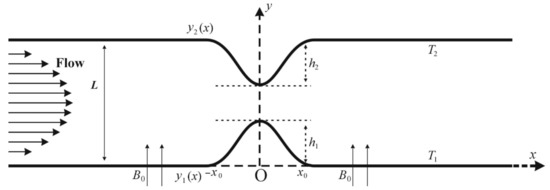
Figure 1.
The channel geometry having a symmetric constriction on each of the walls.
The lower and upper walls are defined, respectively, as:
Here, and denote the respective constriction heights.
The unsteady incompressible Navier–Stokes equations, in system, are given by:
The continuity equation:
The momentum equation:
The energy equation:
where is the radiative heat flux. Expanding about and ignoring higher-order terms, we get .
Then, and .
Hence, Equation (5) becomes
where and represent the velocity components along - and -axes, respectively, in the subscript represents the nanofluid, the pressure, the density, the kinematic viscosity, the temperature, the thermal conductivity, the specific heat, the current density, the magnetic field with the uniform strength across the flow, the electric conductivity, the dynamic viscosity, and the magnetic permeability of the medium. If represents the electric field such that the electric current flows along the normal to the plane of the flow, then . Next, from Ohm’s law
For the steady flow, Maxwell’s equation implies that is constant. For the current study, we suppose that . Then, Equation (7) gives, . Therefore, . Hence, Equation (3) become,
The following quantities are added for obtaining the non-dimensional form of the governing equations:
Here, is the maximum width of the channel, is the period of the flow pulsation, is the characteristic flow velocity, and is the mean absorption coefficient.
The effective thermophysical properties of HNF [10,22,32] are presented as follows: The HNF’s effective dynamic viscosity is given as
Here, and show the volume fractions of NPs and , respectively.
The HNF’s effective density is given as
and in subscripts correspond to the property of and , respectively. Moreover, , and in the subscripts correspond to the property of the hybrid-nanofluid, nanofluid, and base fluid water, respectively. The HNF’s heat capacitance is given as
The HNF’s effective thermal conductivity is given as
where
The thermophysical properties of the base fluid water and the NPs under consideration are shown in Table 1. The properties in Table 1 are given at 24.6 °C. The viscosity of water at 24.6 °C is approximately 0.0000009009 m2/s. Thus, according to Equation (10), m2/s with .

Table 1.
Thermophysical properties of the base fluid water and the two kinds of nanoparticles [10,32].
Using the quantities from Equations (9) and (12) in Equations (2)–(4) and (6) gives
where
2.1. The Boundary Conditions
For the steady case of the flow problem under consideration, the boundary condition, obtained by solving the dimensionless form of Equation (8) and performing some manipulations using Equation (10), are given as follows,
When , the -velocity at the inlet takes the form:
The conditions of the outlet boundary are taken as for fully developed flow for all the variables. The flow is presumably sinusoidal for the pulsatile flow:
Further, and (i.e., no-slip conditions) are assumed on the walls. In the non-dimensional form, the temperature condition at the lower wall, and at the upper wall, .
2.2. The Vorticity-Stream Function Formulation
The transformation from the primitive variables, and , to the vorticity-stream functions, and , is defined as:
The relation for computing the WSS is given by
Here, and denote the normal vector and vorticity at the wall, respectively. As the vorticity and WSS are orthogonal to each other, the WSS can also be determined by the vorticity expression [33].
We differentiate the momentum Equations (16) and (17) with respect to and , respectively. Then, from their subtraction, we get
Additionally, the stream function equation (Poisson equation) is given as
2.3. Transformation of Coordinates
By incorporating the following coordinate transformation, the constricted portion of the channel is treated as a straight one:
In the system, and represent the lower and upper walls of the channel, respectively. Moreover, Equations (18) and (24), (25) assume the form as
where
The velocity components and in terms of take the forms
In the new coordinate system, the initial conditions for and are given by
Furthermore, the boundary conditions for the walls in system for and are given as
where denotes the pulsating amplitude. The steady and pulsatile flow conditions are given by and , respectively. For the temperature, the boundary conditions after the transformation are given as at and at .
The other concerning nondimensional physical quantities include the skin friction coefficient and Nusselt number, defined by
where and are defined as
After using dimensionless variables from (9) and the coordinate transformation from (26), we get
3. Results and Discussion
The problem Equations (27)–(29) subject to boundary conditions, including (32)–(34), are solved numerically using FDM, as in [34,35,36,37,38,39]. The domain is discretized by choosing the grid points with the step-sizes and in -direction and -direction, respectively. For time integration of the solution, a fixed step size is used. The solution at time level is used to obtain the solution is at time level , for . Firstly, Equation (28) is solved for . The linear system obtained through the finite difference discretizations is solved using the Tri-Diagonal Matrix Algorithm (TDMA). Secondly, Equations (27) and (29) are solved using the ADI (Alternating Direction Implicit) method for and , respectively. The linear systems obtained through the finite difference discretizations are solved using the TDMA at each of the two half-steps of the ADI method. A detailed description of the algorithm can be found in [38]. The values of the step sizes are taken as follows to ensure the consistency of the numerical scheme: for the pulsatile flow with , and . The computations for the present study are performed in a sequential fashion. The results can be found by parallel computing for time-efficient solutions [40].
In the current study, the computational domain, considered as and , is discretized by a grid of elements. The length of the constriction is considered as The constrictions on the lower and upper walls are assumed to have heights ; hence, at the throat of the constriction, the channel width remains 30% of the maximum channel width.
The pulsatile motion is modeled by adding in the inflow boundary condition the sinusoidal time-dependent function . For a comparison of the behaviors of /water HNF with /water NF, the effects of the physical parameters including , , , and are studied on the non-dimensional streamwise velocity and temperature profiles. We performed simulations for a long enough time that, in most cases, the results are displayed at selected time instants and axial locations, especially (throat of the constriction) and (in the lee of the constriction) where the fluid enters in the low-pressure zone from the high-pressure zone. For a pulse cycle, is the acceleration phase and is the deceleration phase.
For validation, the present results for the pulsatile flow of the base fluid (i.e., with ) are compared with those obtained by Bandyopadhyay and Layek [35] in the case of Newtonian fluid without the heat effect. Figure 2 shows a good agreement of the present results, specifically the wall shear stresses, with [35] for and at .
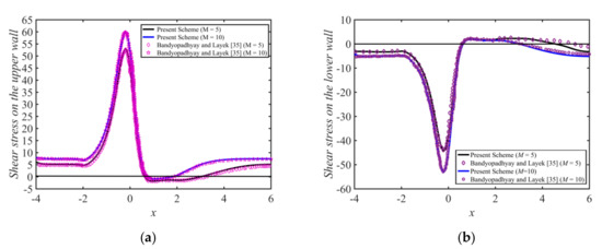
Figure 2.
Wall shear stress distributions for the pulsatile flow, for at , , , and : (a) on the lower wall, and (b) on the upper wall.
The effects of pure water, /water, /water on the WSS at both walls are computed for a complete pulse cycle while fixing the parameters as , , , , and . The results are shown in Figure 3. It is seen that during a complete period, the wall shear stress varies considerably, especially in the vicinity and downstream of the constriction. However, no major changes are observed upstream of the constriction on the WSS. Over the duration , the peak value of WSS decreases and reaches its highest value at at peak flow time. The flow separation area rises during this period of the time cycle. After that, during , the flow starts to decelerate, and the WSS also decreases, but the area of the flow separation tends to increase. The WSS is oscillating, and its sign changes at zero net flow rate, i.e., at
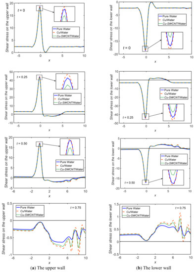
Figure 3.
Comparison of pure water, /water, and /water for WSS with , , , , and , at .
Figure 4 presents a comparison among the pure water, /water NF, and /water HNF by fixing the parameters as , , , , and . The velocity profile for pure water is observed to be the highest, followed by the NF and then the HNF. For the HNF, the particle concentration in the fluid is even higher than that of the base fluid and the NF, which causes enhancement of the density and dynamic viscosity. The flow velocity experiences reduction accordingly. The peak value of tends to rise, and the curves appear to be parabolic for . At , is dropped substantially, and backflow occurs near the walls. Figure 5 shows -profiles at . At , in the vicinity of the limiting point of the constriction downstream, a backflow is observed.
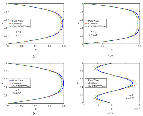
Figure 4.
Comparison of pure water, /water, and /water for velocity profiles for , , , , and at (a) , (b) , (c) , and (d) .
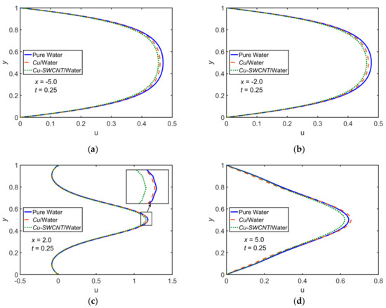
Figure 5.
Comparison of pure water, /water, and /water for velocity profiles for , , , , , and at (a) , (b) , (c) , and (d) .
A comparison among the pure water, /water NF, and /water HNF for the temperature profiles computed with , , , , and . In Figure 6, the profiles are shown at for a complete pulse cycle. However, in Figure 7, the profiles are shown at four different -locations at . It is noticed that the HNF hits higher temperatures compared to the NF. A rapid rise in temperature is due to the hybrid nature of the nanofluid since it increases the thermal conductivity.
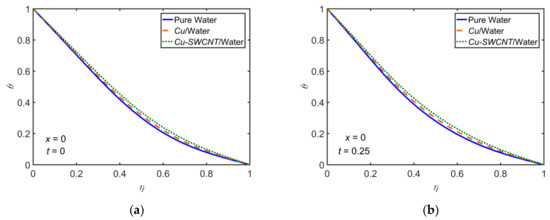
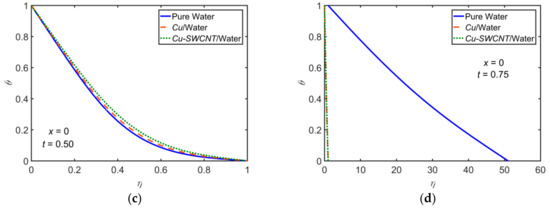
Figure 6.
Comparison of pure water, /water, and /water for the temperature profiles for , , , , and at (a) , (b) , (c) , and (d) .
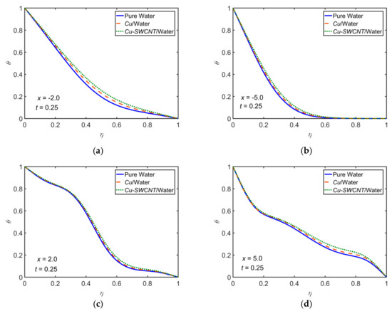
Figure 7.
Comparison of pure water, /water, and /water for the temperature profiles for , , , , , and at (a) , (b) , (c) , and (d) .
Figure 8 and Figure 9 illustrate the behavior of and profiles, respectively, for the variation of to make a comparison between the NF and the HNF. The other parameters are fixed as , , , and . It is observed that the velocity is greater for the NF than the HNF. The velocity increases as the magnetic field strength is increased. That is, the viscous boundary layer thickness is decreased for higher values of This is due to the production of a resistive Lorentz force, whose strength increases with increasing values of . The HNF temperature profile is slightly higher than that of the NF. The thermal boundary layer thickness decreases, resulting in a decline of the temperature profile with enhancement in the magnetic field strength. The appreciation in maximizes the velocity gradient and minimizes the temperature gradient at the boundary.
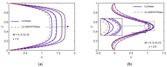
Figure 8.
Comparison of /water and /water for the velocity profiles for with , , , , , and at (a) (b) .
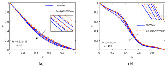
Figure 9.
Comparison of /water and /water for the temperature profiles for with , , , , , and at (a) (b) .
Figure 10 and Figure 11 illustrate the behavior of the velocity and temperature profiles, respectively, for the variation of to compare the NF and HNF. The other parameters are fixed as: , , , and . It is observed that the velocity is greater for the NF than the HNF. The velocity decreases with increment in , i.e., the viscous boundary layer thickness increases with . The HNF temperature profile is slightly higher than that of the NF. The thermal boundary layer thickness decreases, resulting in a decrease of the temperature profile with increasing values of . The velocity exhibits a parabolic profile at . The profiles are not parabolic as some backflow in the vicinity of the walls is observed at . The backflow reduces with an increase in .
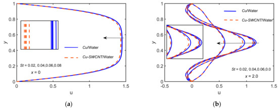
Figure 10.
Comparison of /water and /water for the velocity profiles for with , , , , , and at (a) (b) .
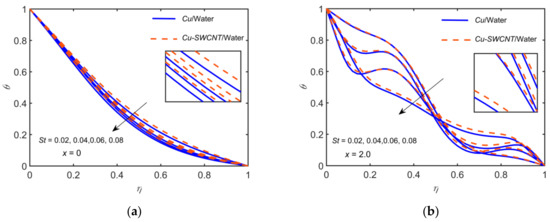
Figure 11.
Comparison of /water and /water for the temperature profiles for with , , , , , and at (a) (b) .
Figure 12 illustrates the behavior of the temperature profiles for the variation of to compare the NF and HNF. The other parameters are fixed as: , , , and . The HNF temperature profile is slightly higher than that of the NF. The thermal boundary layer thickness decreases as the increases, resulting in a decline in the temperature profile at both locations. The rising values of cause a reduction in thermal diffusivity. Consequently, the temperature of the fluid is lowered.
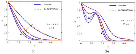
Figure 12.
Comparison of /water and /water for the temperature profiles for , with , , , , and at (a) (b) .
Figure 13 illustrates the behavior of the temperature profiles for the variation of to compare the NF and HNF. The other parameters are fixed as , , , and . Appreciation in enhances the temperature of the fluids. It is noticed that the temperature profile of the HNF is slightly higher than that of the NF. The thermal boundary layer thickness increases, resulting in the rise of temperature as is increased. Physically it is due to the fact that the mean absorption coefficient decreases, which boosts thus the radiative heat transfer rate is increased.
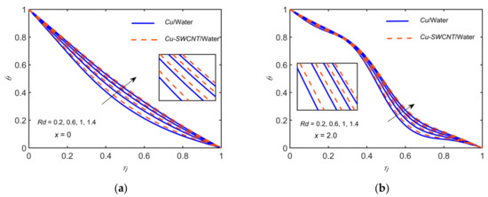
Figure 13.
Comparison of /water and /water for the temperature profiles for with , , , , , and at (a) (b) .
Figure 14 and Figure 15 illustrate the behavior of the velocity and temperature profiles, respectively, for the variation of solid volume fraction to compare the NF and HNF. The other parameters are fixed as , , and . The velocity is greater for the NF than that of the HNF. We further observe that the velocity decreases for enhancing the solid volume fraction i.e., the viscous boundary layer thickness increases with increasing values of . The temperature distribution and momentum boundary layer thickness show a rising trend with the solid volume fraction. It is also clear from the figure that the HNF exhibits a higher temperature profile than the NF. The velocity exhibits a parabolic profile at . The profiles are not parabolic as some backflow in the vicinity of the walls is observed at .
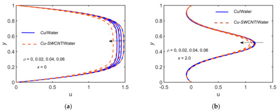
Figure 14.
Comparison of /water and /water for the velocity profiles for with , , , , and at (a) (b) .
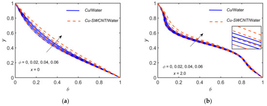
Figure 15.
Comparison of /water and /water for the temperature profiles for with , , , , , and at (a) (b) .
The effects of and for /water on the WSS on both walls are computed while fixing the parameters as , , , , and . The results are shown in Figure 16, and the streamlines distribution plots are shown Figure 17 for . As expected, the magnitudes of the peak values of the profiles are lower for the lower . The profile wave and the eddies downstream of the constriction are weaker for the lower Reynold number.
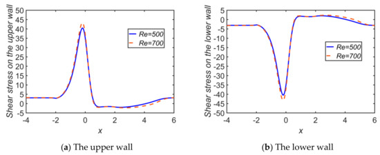
Figure 16.
Comparison of WSS for and in case of /water, setting , , , and , at .
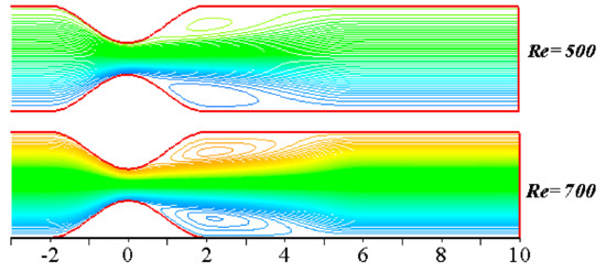
Figure 17.
Comparison of the streamlines for and in case of /water, setting , , , and , at .
The effects of , , and on the Nusselt number and skin friction profiles are shown in Figure 18 and Figure 19, respectively. It is observed that the Nusselt number increases for higher values of and , but decreases for increasing . Additionally, the skin friction coefficient increases for an increase in the values of . However, it remains unchanged for and .
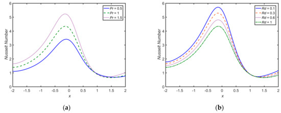
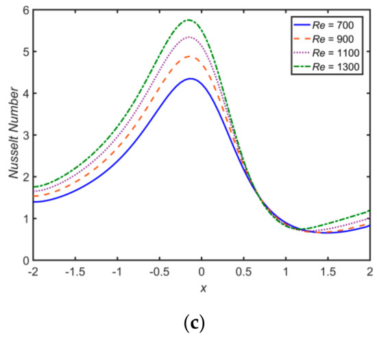
Figure 18.
Nusselt profiles for (a) , and ; (b) , and ; and (c) , and ; with and , at .
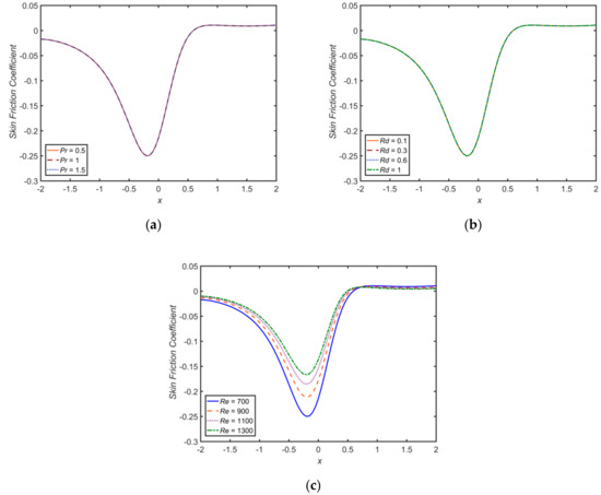
Figure 19.
Skin friction profiles for (a) , , and ; (b) , , , and ; and (c) , , , and ; with and , at .
The streamlines, vorticity, and temperature distribution plots with , , , , and are shown in Figure 20 for comparison among pure water, /water NF and /water HNF. The formation of vertical eddies in the vicinity of the walls can be observed. Over time, the eddies grow for the HNF and slowly occupy a major part of the channel downstream of the constriction. The inclusion of multiple types of nanoparticles adds more energy. This results in higher increments in the temperature as well as the thickness of the thermal boundary layer. A rapid rise in the temperature is due to the HNF since it increases the thermal conductivity.
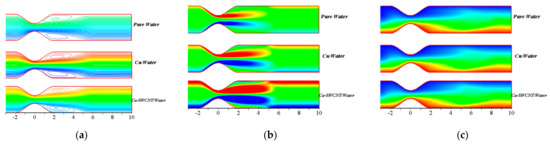
Figure 20.
Comparison of pure water, /water, and /water for (a) Streamlines, (b) vorticity, and (c) temperature distributions with , , , , and , at the maximum flow rate ( ).
4. Concluding Remarks
In this research, the comparison between the behavior of a traditional NF and an emerging HNF in the presence of viscous incompressible MHD pulsatile fluid flow over a rectangular channel is numerically investigated. The comparison between the behavior of the pure water, /water NF, and /water HNF over the velocity, temperature, and WSS distributions are visualized graphically. The impacts of each of , , , and on the flow profiles are studied. The summary of the impacts is as follows:
- The effects of the pure water, /water, and /water on the WSS at both walls are computed. The flow separation area rises during the duration . After that, the flow starts to decelerate, during and the WSS also decreases, but the area of the flow separation tends to increase.
- Density and dynamic viscosity are the factors of fluid velocity reduction, which is enhanced by hybridity as more immense particles are introduced, so the velocity reduces when comparing the pure water, the NF, and the HNF.
- A rapid rise in temperature is observed due to the HNF since it increases the thermal conductivity when comparing the pure water, the NF, and the HNF. Hence, it is interpreted that the HNF hits higher temperatures compared to the NF.
- The increasing values of reduce the overall density, which raised the temperature of the HNF within the boundary layer. Finally, the appreciation in maximizes the velocity gradient and minimizes the temperature gradient at the boundary.
- The HNF temperature profile is slightly higher than that of the NF in the case of varying and . The thermal boundary layer thickness decreases, resulting in a decrease of the temperature profile with increasing values of and . The higher value of number causes a reduction in the thermal diffusivity.
- The thermal boundary layer thickness increases, resulting in the rise of temperature as is increased. Temperature profile and thermal boundary layer thickness are enhanced by increasing the values of .
- Velocity decreases for enhancing the solid volume fraction i.e., the viscous boundary layer thickness increases with increasing values of . Additionally, the HNF exhibits a higher temperature profile than the NF.
- The HNF is observed to be a better thermal conductor as compared with the traditional NF.
- The Nusselt number increases for higher values of and , but decreases for increasing .
- The skin friction coefficient increases for an increase in the values of ; however, it remains unchanged for and .
Author Contributions
Conceptualization, A.A., Z.B. and Z.A.; methodology, A.A. and Z.B.; software, Z.B. and M.U.; validation, G.S. and Z.A.; formal analysis, A.A. and Z.B.; investigation, A.A., M.U. and Z.B.; writing—original draft preparation, A.A. and Z.B.; writing—review and editing, A.A., G.S. and Z.A.; visualization, M.U. and Z.B.; supervision, A.A., G.S. and Z.A.; project administration, A.A. and G.S. All authors have read and agreed to the published version of the manuscript.
Funding
This research received no external funding.
Institutional Review Board Statement
Not applicable.
Informed Consent Statement
Not applicable.
Conflicts of Interest
The authors declare no conflict of interest.
References
- Saidur, R.; Leong, K.Y.; Mohammed, H.A. A review on applications and challenges of nanofluids. Renew. Sustain. Energy Rev. 2011, 15, 1646–1668. [Google Scholar] [CrossRef]
- Choi, S.U.S. Enhancing thermal conductivity of a fluids with nanoparticles. ASME 1995, 66, 99–105. [Google Scholar]
- Buongiorno, J. Convective transport in nanofluids. Int. J. Heat Mass Trans. 2006, 128, 240–250. [Google Scholar] [CrossRef]
- Kuznetsov, A.V.; Nield, D.A. Natural convective boundary layer flow of a nanofluid past a vertical plate. Int. J. Therm. Sci. 2010, 49, 243–247. [Google Scholar] [CrossRef]
- Wong, K.V.; Leon, O.D. Applications of NFs: Current and Future. Adv. Mech. Eng. 2010, 2, 1–11. [Google Scholar] [CrossRef]
- Akbar, N.S. Metallic NPs analysis for the peristaltic flow in an asymmetric channel with MHD. IEEE Trans. Nanotech. 2014, 13, 357–361. [Google Scholar] [CrossRef]
- Sheikholeslami, M.; Hayat, T.; Alsaedi, A. Numerical study for external magnetic source influence on water based NF convective heat transfer. Int. J. Heat Mass Trans. 2017, 106, 745–755. [Google Scholar] [CrossRef]
- Hayat, T.; Rashid, M.; Imtiaz, M.; Alsaedi, A. Nanofluid flow due to rotating disk with variable thickness and homogeneous–heterogeneous reactions. Int. J. Heat Mass Trans. 2017, 113, 96–105. [Google Scholar] [CrossRef]
- Paul, D.; Mandal, G. Thermal radiation and MHD effects on boundary layer flow of micropolar nanofluid past a stretching sheet with non-uniform heat source/sink. Int. J. Mech. Sci. 2017, 136, 308–318. [Google Scholar] [CrossRef]
- Alizadeh, M.; Dogonchi, A.S.; Ganji, D.D. Micropolar nanofluid flow and heat transfer between penetrable walls in the presence of thermal radiation and magnetic field. Case Stud. Therm. Eng. 2018, 12, 319–332. [Google Scholar] [CrossRef]
- Dib, A.; Haiahem, A.; Bou-said, B. Approximate analytical solution of squeezing unsteady nanofluid flow. Powder Technol. 2015, 269, 193–199. [Google Scholar] [CrossRef]
- Cacua, K.; Ordoñez, F.; Zapata, C.; Herrera, B.; Pabón, E.; Buitrago-Sierra, R. Surfactant concentration and pH effects on the zeta potential values of alumina nanofluids to inspect stability. Colloids Surf. A Physicochem. Eng. 2019, 583, 123960. [Google Scholar] [CrossRef]
- Choudhary, R.; Khurana, D.; Kumar, A.; Subudhi, S. Stability analysis of Al2O3/water nanofluids. J. Exp. Nanosci. 2017, 12, 140–151. [Google Scholar] [CrossRef]
- Lim, C.Y.; Lim, A.E.; Lam, Y.C. pH change in electroosmotic flow hysteresis. Anal. Chem. 2017, 89, 9394–9399. [Google Scholar] [CrossRef]
- Lim, A.E.; Lim, C.Y.; Lam, Y.C. Electroosmotic flow hysteresis for dissimilar anionic solutions. Anal. Chem. 2016, 88, 8064–8073. [Google Scholar] [CrossRef]
- Shadloo, M.S. Application of support vector machines for accurate prediction of convection heat transfer coefficient of nanofluids through circular pipes. Int. J. Numer. Methods Heat Fluid Flow 2020. [Google Scholar] [CrossRef]
- Rashidi, M.M.; Nasiri, M.; Shadloo, M.S.; Yang, Z. Entropy Generation in a Circular Tube Heat Exchanger Using Nanofluids: Effects of Different Modeling Approaches. Heat Trans. Eng. 2017, 38, 853–866. [Google Scholar] [CrossRef]
- Huminicl, G.; Huminic, A. Hybrid nanofluids for heat transfer applications—A state of the art review. Int. J. Heat Mass Trans. 2018, 125, 82–103. [Google Scholar] [CrossRef]
- Sarkar, J.; Ghosh, P.; Adil, A. A review on hybrid nanofluids: Recent research, development and applications. Renew. Sustain. Energy Rev. 2015, 43, 164–177. [Google Scholar] [CrossRef]
- Ahmad, S.; Nadeem, S. Application of CNT-based micropolar hybrid nanofluid flow in the presence of Newtonian heating. App. Nanosci. 2020, 10, 1–13. [Google Scholar] [CrossRef]
- Khan, M.; Malik, M.; Salahuddin, T.; Hussian, A. Heat and mass transfer of Williamson nanofluid flow yield by an inclined Lorentz force over a nonlinear stretching sheet. Results Phys. 2018, 8, 862–868. [Google Scholar] [CrossRef]
- Devi, S.S.U.; Devi, S.P.A. Numerical investigation on three dimensional hybrid Cu-Al2O3/water nanofluid flow over a stretching sheet with effecting Lorentz force subject to Newtonian heatings. Can. J. Phys. 2016, 94, 490–496. [Google Scholar] [CrossRef]
- Suleman, M.; Ramzan, M.; Ahmad, S.; Dianchen, L.; Muhammad, T.; Chung, J.D. A numerical simulation of silver-water nanofluid flow with impacts of Newtonian heating and homogeneous- heterogeneous reactions past a nonlinear stretched cylinder. Symmetry 2019, 11, 295. [Google Scholar] [CrossRef]
- Nadeem, S.; Hayat, T.; Khan, A.U. Numerical study of 3D rotating hybrid SWCNT-MWCNT flow over a convectively heated stretching surface with heat generation/absorption. Phys. Scr. 2019, 94, 075202. [Google Scholar] [CrossRef]
- Suresh, S.; Venkitaraj, K.; Selvakumar, P.; Chandrasekar, M. Effect of Al2O3/water hybrid nanofluid in heat transfer. Exp. Therm. Fluid Sci. 2012, 8, 54–60. [Google Scholar] [CrossRef]
- Momin, G.G. Experimental investigation of mixed convection with Al2O3/water and hybrid nanofluid in inclined tube for laminar flow. Int. J. Sci. Res. Sci. 2013, 2, 195–202. [Google Scholar]
- Prakash, M.; Devi, S.S.U. Hydromagnetic hybrid Al2O3-Cu/water nanofluid flow over a slendering stretching sheet with prescribed surface temperature. Asian J. Hum. Soc. Sci. 2016, 6, 1921–1936. [Google Scholar] [CrossRef]
- Bahiraei, M.; Mazaheri, N. Application of a novel hybrid nanofluid containing graphene platinum nanoparticles in a chaotic twisted geometry for utilization in miniature devices thermal and energy efficiency considerations. Int. J. Mech. Sci. 2018, 138, 337–349. [Google Scholar] [CrossRef]
- Eshgarf, H.; Kalbasi, R.; Maleki, A.; Shadloo, M.S.; Karimipour, A. A review on the properties, preparation, models, and stability of hybrid nanofluids to optimize energy consumption. J. Therm. Anal. Calorim. 2020. [Google Scholar] [CrossRef]
- Vasua, B.; Dubey, A.; Bég, O.A.; Gorla, R.S.R. Micropolar pulsatile blood flow conveying nanoparticles in a stenotic tapered artery: Non-Newtonian pharmacodynamic simulation. Comput. Biol. Med. 2020, 126, 104025. [Google Scholar] [CrossRef]
- Priyadharshini, S.; Ponalagusamy, R. Mathematical modelling for pulsatile flow of Casson fluid along with magnetic nanoparticles in a stenosed artery under external magnetic field and body acceleration. Neural Comput. Appl. 2019, 31, 813–826. [Google Scholar] [CrossRef]
- Sheikholeslami, M.; Ganji, D.D. Heat transfer of Cu-water nanofluid flow between parallel plates. Powder Technol. 2013, 235, 873–879. [Google Scholar] [CrossRef]
- Wu, J.Z.; Ma, H.Y.; Zhou, M.D. Vorticity and Vortex Dynamics; Springer: Berlin/Heidelberg, Germany, 2006. [Google Scholar]
- Bandyopadhyay, S.; Layek, G.C. Numerical computation of pulsatile flow through a locally constricted channel. Commun. Nonlinear Sci. Numer. Simul. 2011, 16, 252–265. [Google Scholar] [CrossRef]
- Bandyopadhyay, S.; Layek, G.C. Study of magnetohydrodynamic pulsatile flow in a constricted channel. Commun. Nonlinear Sci. Numer. Simul. 2012, 17, 2434–2446. [Google Scholar] [CrossRef]
- Ali, A.; Farooq, H.; Abbas, Z.; Bukhari, Z.; Fatima, A. Impact of Lorentz force on the pulsatile flow of a non-Newtonian Casson fluid in a constricted channel using Darcy’s law. Sci. Rep. 2020, 10, 10629. [Google Scholar] [CrossRef]
- Ali, A.; Umar, M.; Bukhari, Z.; Abbas, Z. Pulsating flow of a micropolar-Casson fluid through a constricted channel influenced by a magnetic field and Darcian porous medium: A numerical study. Results Phys. 2020, 19, 103544. [Google Scholar] [CrossRef]
- Bukhari, Z.; Ali, A.; Abbas, Z.; Farooq, H. The pulsatile flow of thermally developed non-Newtonian Casson fluid in a channel with constricted walls. AIP Adv. 2021, 11, 025324. [Google Scholar] [CrossRef]
- Ali, A.; Fatima, A.; Bukhari, Z.; Farooq, H.; Abbas, Z. Non-Newtonian Casson pulsatile fluid flow influenced by Lorentz force in a porous channel with multiple constrictions: A numerical study. Korea Aust. Rheol. J. 2021, 33, 79–90. [Google Scholar] [CrossRef]
- Ali, A.; Syed, K.S. An outlook of high performance computing infrastructures for scientific computing. Adv. Comput. 2013, 91, 87–118. [Google Scholar]
Publisher’s Note: MDPI stays neutral with regard to jurisdictional claims in published maps and institutional affiliations. |
© 2021 by the authors. Licensee MDPI, Basel, Switzerland. This article is an open access article distributed under the terms and conditions of the Creative Commons Attribution (CC BY) license (https://creativecommons.org/licenses/by/4.0/).