Abstract
The diffuser total efficiency was formulated and defined based on the generalized actuator disc model for the index of the efficiency of the diffuser-alone of the diffuser-augmented wind turbines. An optimization method to maximize the diffuser total efficiency was developed using a genetic algorithm and axisymmetric computational fluid dynamics. A case study was conducted for a 10% chord-to-diameter ratio, 2% thickness-to-chord plate, and the crest position at 50% chord of the diffuser. The optimal result showed a diffuser total efficiency of 1.087. Furthermore, 1392 (=48 population × 29 generations) simulation cases of the optimization process showed that high diffuser total efficiency appears at a low-drag coefficient, high-lift coefficient, and 15–25% low diffuser height-to-chord ratio.
1. Introduction
It is known that wind turbine output can be increased by installing an appropriate diffuser around the rotor. Such wind turbines are called diffuser-augmented wind turbines (DAWTs). Over the years, the size of wind turbines has been increasing incrementally to obtain improved economies of scale. The size is heavily dependent on the design and coupled analysis methods of the turbines as well as the design standards and guidelines. The design and analysis theory and methods of DAWTs are still not mature compared to conventional wind turbines. At present, no complete coupled analysis method for DAWT is available. The FloDesign-Ogin Model 2.2 (150 kW, 20 m rotor diameter) [1], Riamwind Windlens 100 kW (12.8 m rotor diameter) [2], and Vortec 7 (7.3 m rotor diameter) [3] are relatively large DAWTs. Even for these DAWTs, aeroelastic analysis is not very necessary, as they are small and stiff. The development of many DAWTs, such as the Windlens 100 kW [4,5], mainly relied on parametric studies driven by computational fluid dynamics (CFD) and wind tunnel tests. Therefore, the development of aeroelastic simulation methods has become necessary to follow the modern design approach that is based on current design standards and guidelines. Theoretical studies on previous aerodynamics analyses are well summarized in Bontempo and Manna [6]. The Betz model [7] is a classical model for DAWTs and has been extended to several other models. One of those models is the Lilley and Rainbird model [8], which was applied to the design of the DAWT of Vortec 7 in the 1980s. Van Bussel [9] developed a model for ducts wherein the friction loss can be ignored, introducing the diffuser area ratio and the back pressure of the diffuser. Jamieson [10] formulated the generalized blade-element and momentum theory, as a theory of the DAWT rotor, by combining the generalized momentum and blade-element theories. Liu and Yoshida [11] later extended the theory to turbulent wake conditions.
Several useful indexes of DAWTs have been proposed so far. The “power coefficient”, which is the ratio of the power acquired by the rotor to the wind power represented by the wind speed at the rotor center and the rotor area, is a common index for wind turbine efficiency. However, it is not suitable as an index of efficiency or the design target because an extremely large power coefficient can also be obtained by installing an extremely large diffuser around the rotor. Instead, the “total power coefficient” based on the area of the diffuser exit is recognized as a fair and an efficiency index of DAWTs. The “diffuser efficiency”, which is defined as the average speedup ratio at the rotor plane in the present study, is defined as the ratio between the actual pressure rise at the diffuser exit to the inviscid ones to consider the losses from viscosity effects as the friction and the separation in the previous researches [12]. The supplement “speedup ratio” is added to that as much as possible in the present paper to avoid the confusion. The “augmentation ratio”, which is the ratio between the powers of the DAWT and the wind turbine without the diffuser, is another important parameter for DAWTs. These indexes are hard to use for the optimization of diffuser solo because they are defined as the performance of DAWTs rather than for diffuser-alone. However, these indexes cannot be used for diffuser-alone of DAWTs. Although the common purpose of the diffuser is to increase the wind speed at the rotor plane, there is no clear index for the efficiency of the diffuser-alone.
Aerodynamic specifications of diffusers are defined by the general dimensions as the internal diameter, cross-sectional shape, and their relative position to the rotor plane. One of the early DAWTs by Igra adopted a NACA airfoil for the cross-section of the diffuser [12]. Since then, most of the diffuser cross-sectional shapes have been developed by numerical simulations and experiments. However, no specific reference is found for extensive optimization of diffuser solo. The research of Oka, et al. [13] is distinctive. The genetic algorithm was applied to optimize the rotor and diffusers of a DAWT regarding the total power coefficient. However, it is worthy of special mention because the diffuser is optimized considering the effects of the rotor loads, it should be evaluated regarding the convergence because the parameters of the diffuser configuration and the rotor loads are determined by the fitting of the several control points.
Considering the aforementioned limitations in the existing efficiency indexes, the “diffuser total efficiency” is formulated using the generalized actuator disc model as an index of the efficiency of the diffuser. An optimization method was also developed by axisymmetric two-dimensional CFD and genetic algorithm (GA) to maximize the total diffuser efficiency. Furthermore, a case study was conducted for typical conditions for diffusers of DAWTs.
2. Diffuser Total Efficiency
In this section, the performance indicators for the diffuser of a DAWT are formulated. Figure 1 shows the representative dimensions of a DAWT diffuser and the airflow conditions. The diffuser has an annular shape with the chord length c, the height of the diffuser h, and the inner diameter D on the rotor plane; the outer or exit diameter is D + 2h.
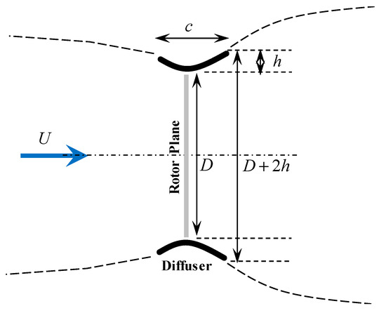
Figure 1.
Dimensions of the diffuser cross-section.
The present research is aiming for a more efficient diffuser that shows high speedup ratio (or velocity ratio) with a small external diffuser diameter. Therefore, the influence of the tangential flow is not considered here.
2.1. Generalized Actuator Disc Model
The generalized actuator disc model [10] is an extension of the actuator disc model that provides the relationship between the momentum change rate and the load of the DAWT rotor. According to the theory, the thrust δT and power δP generated by the rotor with width δr at the cross-sectional radius r are given by the following two equations:
where U is the wind speed, ρ is the air density, a is the axial induction factor at the rotor plane, a0 is the axial induction factor of the diffuser without the rotor, and 1 − a0 is the speedup ratio of the diffuser at r.
2.2. Diffuser Efficiency by Generalized Actuator Disc Model
From Equation (2), the power coefficient, which is based on the rotor area, is as follows:
where ζ is the station radius normalized by the rotor radius R, SR is the rotor area, which is assumed to be identical to the diffuser inner diameter in this study and indicates the values in the annulus area.
The maximum values of CP at each ζ and a are given by the following equation from the extreme value condition dδCP/da = 0 for a in Equation (3).
The radial distribution of the rotor at the optimal operation conditions is determined by a, hence, a0, which is not always uniform. In other words, the present theory indicates that the maximum power coefficient of the DAWT depends only on the distribution of the a0, if the a is provided appropriately as Equation (4) by the rotor design. Therefore, design indexes of diffuser alone are formulated as below.
Equation (5) is integrated in the radial direction. Furthermore, it is divided by the maximum value of the rotor efficiency (16/27), known as the “Betz limit” in momentum theory. This ηD is defined as diffuser efficiency in this study.
Here, the diffuser efficiency is identical to the rotor plane averaged speedup ratio.
2.3. Diffuser Total Efficiency
From Equation (6), the diffuser total efficiency ηTD is defined as follows:
where SD is the diffuser exit or external area. As can be observed in Equation (7), the diffuser total efficiency is obtained by the product of a term proportional to ηD and a term that decreases with the h/D of the diffuser geometry.
3. Optimization Method
The optimization procedure is outlined in this section.
3.1. Design Condition
The wind speed and the main specifications of the diffuser, namely the rotor diameter and chord length, are defined here. In the present method, axisymmetric flow is assumed for CFD analyses as shown 3.4. Therefore, the wind direction deviation with respect to the rotor axis is set to 0.
3.2. Diffuser Cross-Sectional Shape
The cross-sectional shape of the diffuser is represented by functions such as a polynomial. The coefficients of these points or function sequences would be design variables. Therefore, the ranges of each parameter are also defined in advance to the optimization.
3.3. Optimization
A GA is used to solve the discontinuous multivariable combinatorial optimization problem. Here, the diffuser total efficiency, ηTD, as shown in the previous section, is used as the evaluation parameter (cost function).
3.4. Analysis
Several methods are available to analyze the wind speed distribution on the virtual rotor plane in the diffuser without the rotor. In this study, considering the enormous number of calculations required for the GA and taking into account the influence of the boundary layer, an axisymmetric two-dimensional CFD is used.
3.5. Convergence Assessment
The analysis and optimization are repeated until the maximum value does not change for generations.
4. Case Study
A case study was conducted to optimize the cross-sectional shape of a diffuser.
4.1. Design Condition
- Wind speed U: 7.0 m/s
- Air density ρ: 1.225 kg/m3
- Ambient pressure: 1013 HPa
- Wind direction: 0° (parallel to the rotor axis)
- Diameter chord length ratio c/D: 0.10.
4.2. Diffuser Cross-Sectional Shape
The diffuser camber yC is defined by the following function in this study.
where x is the chord-wise position and αn is the coefficient of the polynomial. Larger N provides more detailed cross-section shape at the cost of much longer time for the optimization.
The diffuser is assumed to be 2% c of uniform thickness with the leading and trailing edges shaped as semicircles. And the crest position is fixed as 50% c in the present study. The six variables and their ranges are determined as follows:
- Crest position (xCCr): 0.5 c (fixed)
- Leading edge height (yCLE): 0.0 (fixed)
- Crest height at 50% c (yCCr): 0.1 c–0.3 c
- Trailing edge height (yCTE): −0.3 c–0.0 c
- Leading edge inclination (y’CLE): 0.0–2.0
- Crest inclination (y’CCr): 0.0 (fixed)
- Trailing edge inclination (y’CTE): −2.0–−0.5
Considering the purpose of the present section is to show an example of the optimization rather than designing the optimal shape, N = 5 is selected here. The degree of freedom of the present optimization is 4, which is appropriate for the demonstration to be not too complex and not too simple. The ranges of the parameters should be discussed as well as the order of the polynomial for more detailed optimization.
The aforementioned parameters are determined by the rules of the GA. The N + 1 coefficients of Equation (8) are calculated as follows:
Each cross-section is translated such that the crest is aligned with the edge of the rotor plane.
4.3. Optimization
The GA parameters in the optimization are as follows.
- Population: 48 (elite: 16, mating: 16, mutation: 16)
- Evaluation index: Diffuser total efficiency, ηTD
4.4. Analysis
As mentioned earlier, from the viewpoint of productivity and accuracy of the analysis, CFD is used for axisymmetric two-dimensional domains with a central angle of 1°, as shown in Figure 2a. The mesh around the optimal diffuser cross-section is shown in Figure 2b. The diffuser surface is composed of a structured grid of y+ ~ 0.2, and the general part is composed of an unstructured grid. ANSYS Fluent [14] with a k–ω SST turbulence mode is used in this study. The turbulence model is the hybrid model and consists of k-ω model for near the surface and k-ε model for far from the surface. Thus, it is applied to a wide variety of aerodynamic problems because it is advantageous in the stability, estimation of the separation, and furthermore, negative pressure gradient flow.
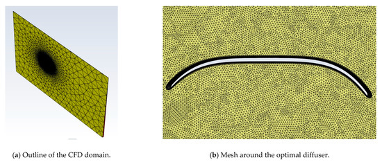
Figure 2.
Computational fluid dynamics (CFD) mesh (wind from the left, 3.4 million of cells).
The analysis domain and boundary conditions are shown in Table 1. The number of cells, 3.4 million, was selected by the mesh-dependence study. Figure 3 shows it provides almost saturated values of the lift and the drag coefficients as the finest one. The lift coefficient Cl and drag coefficient Cd are defined as follows. Here, the lift fl and drag fd are the sectional forces in the radial (positive to center) and longitudinal (positive to wind direction) directions. Because Cl and Cd are defined based on the free stream wind speed U, they show larger values than conventional isolated airfoil sections. These parameters are significant to translate the characteristics of the cross-section to those of the diffuser.

Table 1.
Domain and boundary conditions (D: rotor diameter, c: diffuser chord length).
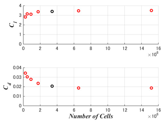
Figure 3.
Lift and drag coefficients to numbers of cells (black: 3.4 million).
4.5. Convergence Assessment
The GA optimization procedure was converged at the 29th generation, as shown in the next section.
5. Analysis Results
5.1. Convergence Assessment
The optimization process of the diffuser total efficiency is shown in Figure 4. Each dot at a generation shows the result with each shape; the top six data are shown by colored marker lines. The maximum value gradually increases with each generation; the other data also converge to the maximum value. Finally, the maximum value remains constant at 1.087 after the 12th generation; this shape is judged as the optimum shape. The total diffuser efficiency is a convenient index for mutual comparison; however, it cannot be used directly for comparison of turbines with and without the diffuser. This is because the effect of blade tip loss is large in a rotor without a diffuser; hence, the total efficiency of DAWT is significantly higher than 1.087 compared to the power coefficient of a wind turbine rotor of the same diameter as that of the diffuser exit.
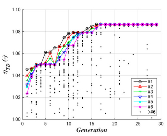
Figure 4.
Optimization progress, with marked lines for top six data.
5.2. Diffuser Cross-Section Shape
The parameters and characteristics of the optimal, which is the maximum total diffuser efficiency, and maximum diffuser efficiency, at the maximum speedup ratio, are shown as (A) and (B) in Table 2. The simulation results are presented in the next section.
Table 2.
Optimization results (c: chord length of the diffuser).
5.3. Wind Speed Distribution
The distributions of the local speedup ratio μ0 along the rotor plane of the two typical cases in Table 2 are shown in Figure 5. The wind speed is higher than the inflow wind speed over the rotor plane. In addition, the maximum speedup ratio case (A) is generally higher than the optimal case (B), particularly near the diffuser surface.
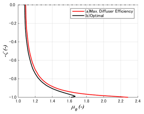
Figure 5.
Wind speed distribution along the rotor plane.
CFD results of (A) the maximum speedup ratio and maximum diffuser efficiency, are shown in Figure 6. Wind from the left and top diffuse inside the diffuser, with the rotor plane located above 50% c as defined in 4.1. It has large height, i.e., large camber, to generate a large speedup ratio at the rotor plane. The flow around the trailing edge is partially separated. The low-pressure region inside the diffuser indicates high lift.
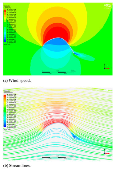
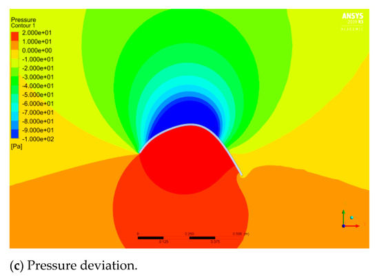
Figure 6.
CFD results of the max. speedup ratio case (A) (7 m/s wind from left, top to inside the diffuser).
In the same manner, those of (B) the optimal, maximum total diffuser efficiency, are shown in Figure 7. This shape does not show high speedup ratio at the rotor plane around the internal surface of the diffuser due to the flat-top shape. However, the large curvature around the front and the rear part of the diffuser generate the low pressure, and the speedup along the rotor plane is close to that of (A).
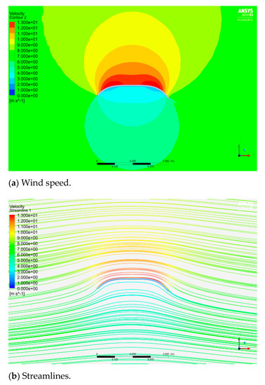
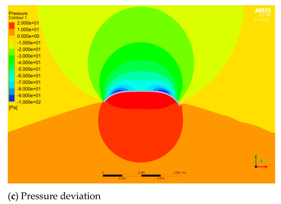
Figure 7.
CFD results of the optimal case (B) (7 m/s wind from left, top to inside the diffuser).
5.4. Diffuser Efficiency (Speedup Ratio)
In the aforementioned optimization process, 1392 (=48 population × 29 generations; with duplication) cases of CFD were analyzed. The cross-sectional characteristics are discussed in this section.
Figure 8 shows the diffuser efficiency (speedup ratio) with respect to the lift coefficient. There is a strong, almost linear correlation between the two; the higher the lift coefficient, the higher the diffuser efficiency. The black points show the top 50%, i.e., 1st–696th (=1392 × 0.50), of the data regarding the diffuser total efficiency. The overall diffuser efficiency becomes higher if the lift coefficient is higher at the same diffuser efficiency (speedup ratio). On the other hand, there is no clear correlation between the diffuser efficiency (speedup ratio) and the drag coefficient as shown in Figure 9.
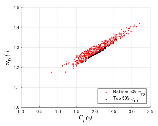
Figure 8.
Diffuser efficiency to lift coefficient.
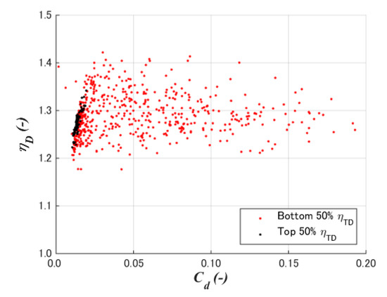
Figure 9.
Diffuser efficiency to drag coefficient.
Although it is not so clear as the lift coefficient, larger diffuser height shows larger diffuser efficiency as shown in Figure 10. It indicates the larger camber is advantageous to increase the speedup ratio by increasing the lift and improving the distribution of the velocity and pressure inside the diffuser as shown in Figure 6 and Figure 7.
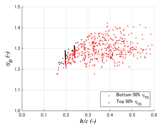
Figure 10.
Diffuser efficiency to diffuser height.
5.5. Diffuser Total Efficiency
Figure 11 shows the relation between the diffuser total efficiency and diffuser efficiency at the maximum speedup ratio. There is no clear correlation between them. A higher speedup ratio does not always result in a higher total diffuser efficiency.
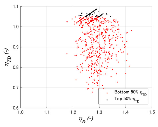
Figure 11.
Diffuser total efficiency vs. diffuser efficiency.
Figure 12 shows the lift coefficient to the drag coefficient, and Figure 13 and Figure 14 show the distributions of the lift and drag coefficients to the height of the diffuser. The top 50% of the data gathered at a small height is 15–25% of the chord length. Moreover, the lift coefficient should be larger around the same h/c. It is also clear that a large diffuser total efficiency appears at a low-drag coefficient.
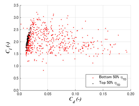
Figure 12.
Lift coefficient to drag coefficient.
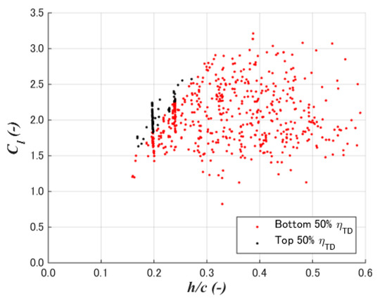
Figure 13.
Lift coefficient to diffuser height.
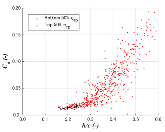
Figure 14.
Drag coefficient to diffuser height.
6. Conclusions
The optimization method of the diffusers of DAWTs was studied in the present study. There are three novelties in this study as below.
- (1)
- An optimization method was developed using an axisymmetric two-dimensional CFD and a genetic algorithm. Here, the diffuser total efficiency, which is not affected by the axial and the tangential inductions by the rotor, was formulated as the index for the diffuser of DAWTs based on the generalized actuator disc model.
- (2)
- A case study of a 2% chord flat plate with a diameter chord length ratio of 0.1 and the crest position at 50% chord length showed the cross-sectional shapes of the maximum diffuser total efficiency is completely different from that of maximum speedup ratio. The former showed a flat top with large curvatures at the front rear of the diffuser, whereas the latter showed large camber as high-lift devices on airplane wings.
- (3)
- The total diffuser efficiency of the case study was shown to be 1.087. Furthermore, 1392 (=48 population × 29 generations) CFD simulations resulted in the optimization process, where it was confirmed that the total diffuser efficiency appears under the condition of low-drag and high-lift coefficients with a 15–25% diffuser height-to-chord ratio.
The following are planned in future studies.
- (1)
- The present result above was calculated under the conditions defined in this study. The crest position and the thickness-to-chord can be changed, and the range and order of the cross-section parameters can be expanded.
- (2)
- The present optimization method is applicable for other diffuser performance indexes. The present results by the total diffuser total efficiency will be compared with the optimization by other diffuser performance parameters as well as experiments.
- (3)
- In addition to the axisymmetric diffuser-alone optimization in the present study, the influence of tangential flow by the rotor, the blade-diffuser interaction, and yaw misalignment will be discussed.
- (4)
- Furthermore, the influences of the axial and the tangential inductions by the rotor, which are not considered in the present study, will be investigated.
Author Contributions
S.Y. designed and organized the research through formulation of the indices, defining the case study conditions, and discussion. M.M. and K.M. conducted computational fluid dynamics and optimization. P.J. contributed to literature review and theoretical parts. All authors have read and agreed to the published version of the manuscript.
Funding
Part of this research is the result obtained from JSPS Grants-in-Aid for Scientific Research (19K04195).
Institutional Review Board Statement
Not applicable.
Informed Consent Statement
Not applicable.
Data Availability Statement
The data presented in this study are available on request from the corresponding author. The data are not publicly available due to their size.
Conflicts of Interest
The authors declare no conflict of interest.
Nomenclatures
| a | Diffuser induction factor. |
| a0 | Diffuser induction factor with no rotor induction. |
| c | Chord length of the diffuser section. |
| Cd | Drag coefficient of the diffuser section. |
| Cl | Lift coefficient of the diffuser section. |
| CP | Power coefficient base on the rotor area. |
| D | Rotor diameter or diffuser internal diameter. |
| fd | Diffuser section drag force, parallel to the wind. |
| fl | Diffuser section lift force, normal to the wind, positive to the diffuser center. |
| h | Height of the diffuser cross-section. |
| N | Order of the polynomial of the camber line. |
| R | Rotor radius. |
| r | Station radius on the rotor plane. |
| SR | Rotor area. |
| SD | Diffuser swept area. |
| T | Rotor thrust. |
| U | Free stream wind speed. |
| u | Longitudinal wind speed on the rotor plane. |
| x | Chord-wise position of the diffuser section. |
| yC | Camber height of the diffuser section. |
| y’C | Camber slope of the diffuser section. |
| αn | Coefficient of the polynomial of the cross-section camber. |
| ζ | Rotor station radius normalized by the rotor radius. |
| ηD | Diffuser efficiency. |
| ηTD | Diffuser total efficiency. |
| μ0 | Local speedup ratio, i.e., wind speed at the rotor normalized by the free stream wind speed. |
| ρ | Air density. |
Subscripts
| Cr | Crest of the diffuser section. |
| LE | Leading edge of the diffuser section. |
| TE | Trailing edge of the diffuser section. |
Abbreviations
| CFD | Computational Fluid Dynamics. |
| DAWT | Diffuser-Augmented Wind Turbine. |
| GA | Genetic Algorithm. |
| LE | Leading Edge. |
| TE | Trailing Edge. |
References
- Gipe, P. FloDesign-Ogin, Wind-Works, 22 May 2020. Available online: http://www.wind-works.org/cms/index.php?id=665 (accessed on 14 November 2020).
- Riamwind Improve Wind Power Generation Efficiency with Wind Lens, 9 May 2020. Available online: http://www.riamwind.co.jp/english/introduction.html (accessed on 14 November 2020).
- Gipe, P. Vortec, Wind-Works. Available online: http://www.wind-works.org/cms/index.php?id=662 (accessed on 14 November 2020).
- Ohya, Y.; Uchida, T.; Karasudani, T.; Hasegawa, M.; Kume, H. Numerical Studies of Flow around a Wind Turbine Equipped with a Flanged-Diffuser Shroud Using an Actuator-Disk Model. Wind Eng. 2012, 36, 455–472. [Google Scholar] [CrossRef]
- Ohya, Y.; Karasudani, T. A Shrouded Wind Turbine Generating High Output Power with Wind-lens Technology. Energies 2010, 3, 634–649. [Google Scholar] [CrossRef]
- Bontempo, R.; Manna, M. Diffuser Augmented Wind Turbines: Review and Assessment of Theoretical Models. Appl. Energy 2020, 280, 115867. [Google Scholar] [CrossRef]
- Betz, A. Energieumsetzungen in Venturidusen. Naturwissenschaften 1929, 17, 160–164. [Google Scholar] [CrossRef]
- Lilley, G.M.; Rainbird, W.J. A Preliminary Report on the Design and Performance of Ducted Windmills; Technical Report 102; Collage of Aeronautics of Cranfield University: Cranfield, UK, 1956. [Google Scholar]
- Van Bussel, G.J.W. The Science of Making More Torque from Wind: Diffuser Experiments and Theory Revisited. J. Phys. Conf. Ser. 2007, 75, 012010. [Google Scholar] [CrossRef]
- Jamieson, P. Innovation in Wind Turbine Design; John Wiley and Sons: Chichester, UK, 2011. [Google Scholar]
- Liu, Y.; Yoshida, S. An Extension of the Generalized Actuator Disc Theory for Aerodynamic Analysis of the Diffuser-Augmented Wind Turbines. Energy 2015, 93, 1852–1859. [Google Scholar] [CrossRef]
- Igra, O. Research and Development for Shrouded Wind Turbines. Energy Convers. 1981, 21, 13–48. [Google Scholar] [CrossRef]
- Oka, N.; Furukawa, M.; Yamada, K.; Kido, K. Aerodynamic Design for Wind-lens Turbine Using Optimization Technique. In Proceedings of the ASME 2013 Fluids Engineering Division Summer Meeting, FEDSM 2013, Incline Village, NV, USA, 7–11 July 2013. [Google Scholar]
- ANSYS. ANSYS Fluent: Canonsburg, PA, USA. 2019. Available online: https://www.ansys.com/ja-jp/products/fluids/ansys-fluent (accessed on 4 February 2021).


Publisher’s Note: MDPI stays neutral with regard to jurisdictional claims in published maps and institutional affiliations. |
© 2021 by the authors. Licensee MDPI, Basel, Switzerland. This article is an open access article distributed under the terms and conditions of the Creative Commons Attribution (CC BY) license (http://creativecommons.org/licenses/by/4.0/).