Diffuser Total Efficiency Using Generalized Actuator Disc Model and Its Maximization Method
Abstract
1. Introduction
2. Diffuser Total Efficiency
2.1. Generalized Actuator Disc Model
2.2. Diffuser Efficiency by Generalized Actuator Disc Model
2.3. Diffuser Total Efficiency
3. Optimization Method
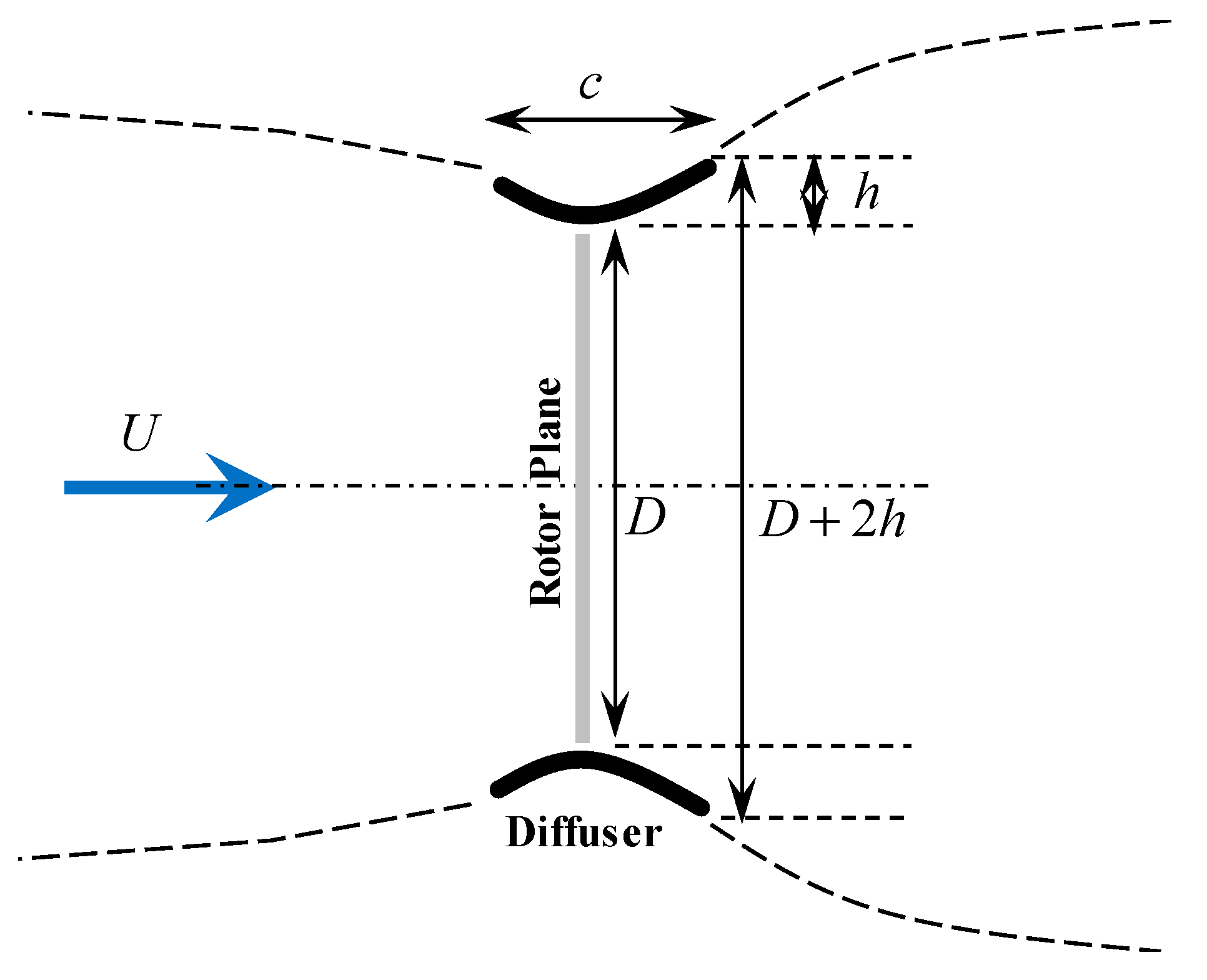
3.1. Design Condition
3.2. Diffuser Cross-Sectional Shape
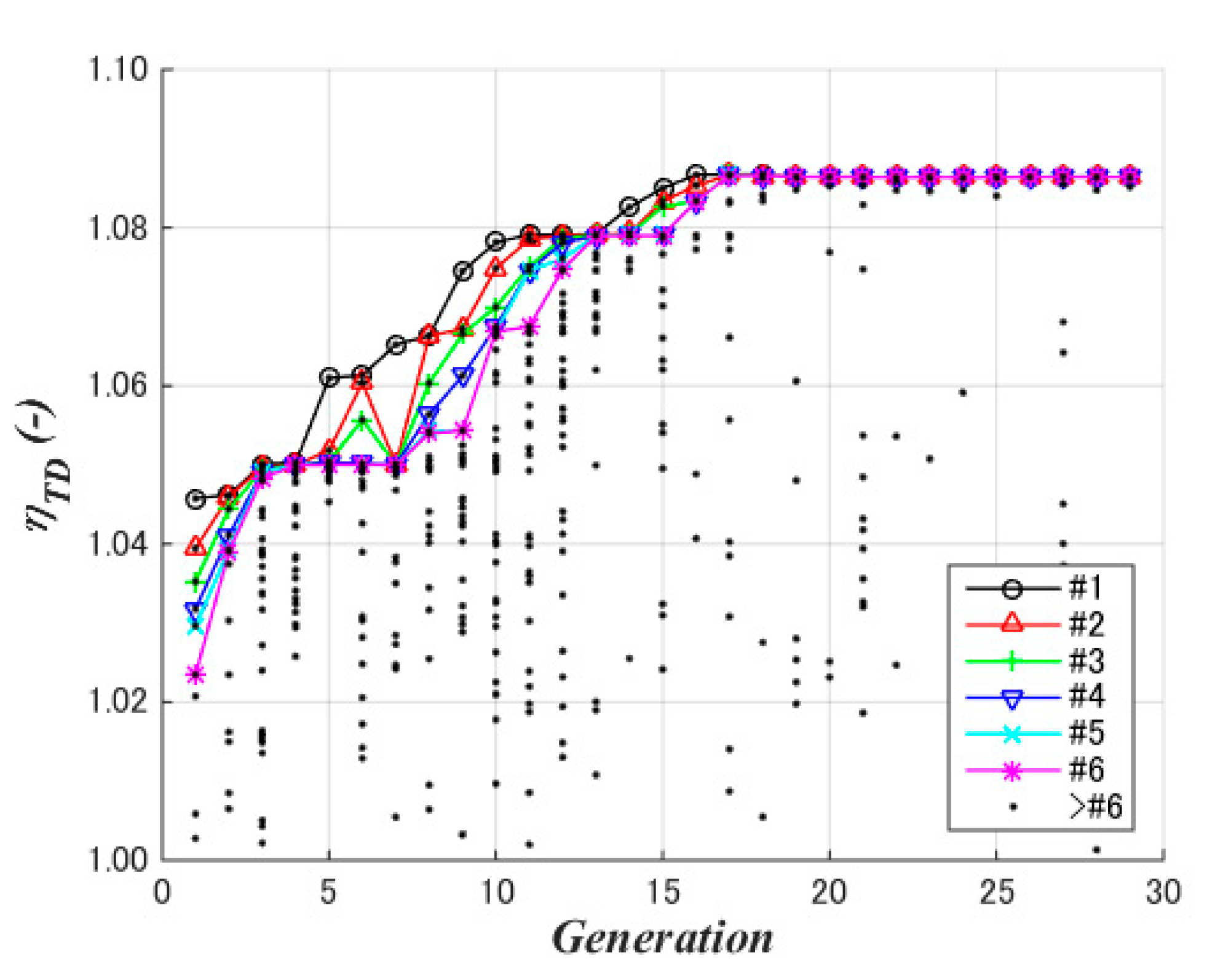
3.3. Optimization
3.4. Analysis
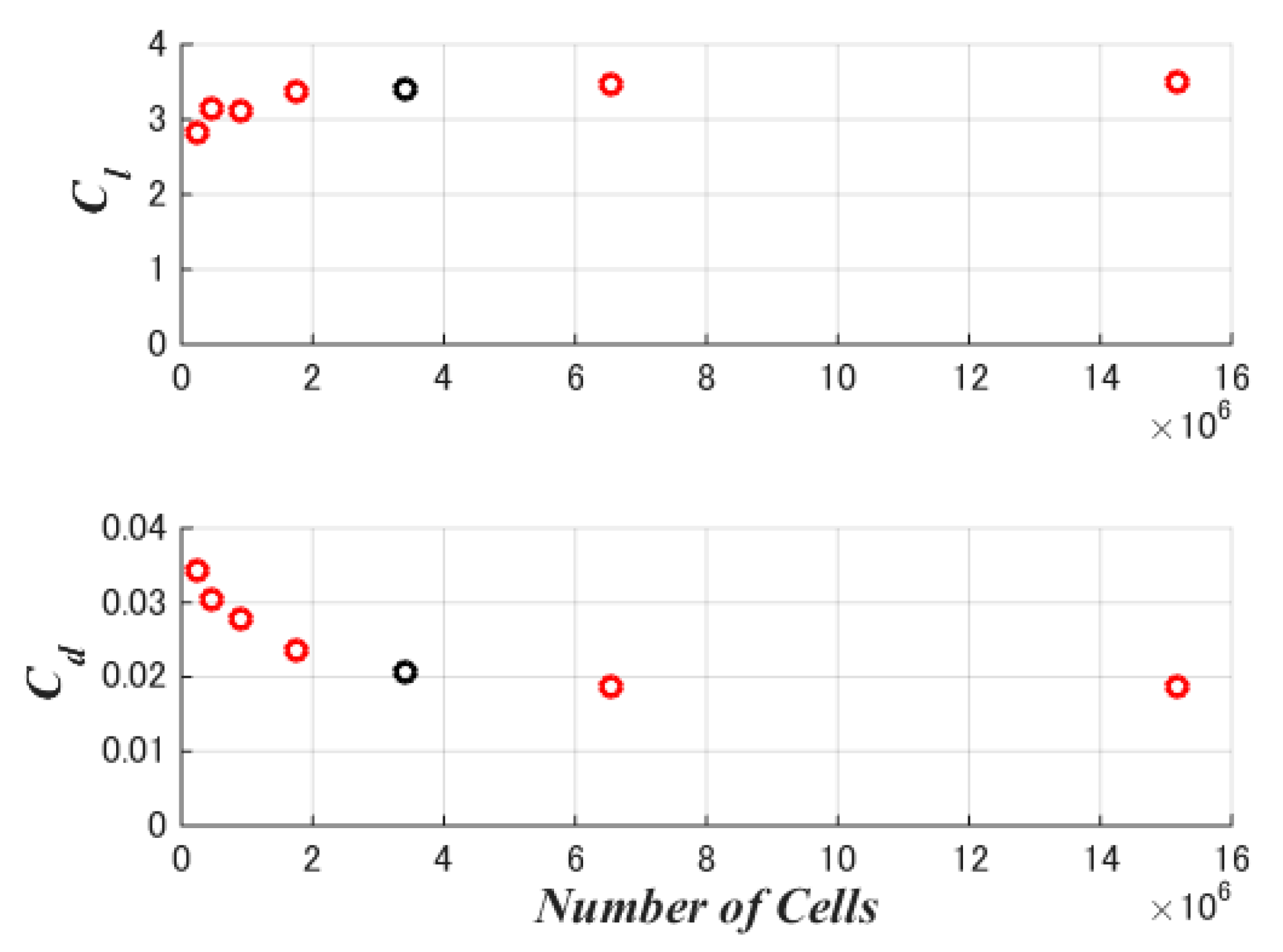
3.5. Convergence Assessment
4. Case Study
4.1. Design Condition
- Wind speed U: 7.0 m/s
- Air density ρ: 1.225 kg/m3
- Ambient pressure: 1013 HPa
- Wind direction: 0° (parallel to the rotor axis)
- Diameter chord length ratio c/D: 0.10.
4.2. Diffuser Cross-Sectional Shape
- Crest position (xCCr): 0.5 c (fixed)
- Leading edge height (yCLE): 0.0 (fixed)
- Crest height at 50% c (yCCr): 0.1 c–0.3 c
- Trailing edge height (yCTE): −0.3 c–0.0 c
- Leading edge inclination (y’CLE): 0.0–2.0
- Crest inclination (y’CCr): 0.0 (fixed)
- Trailing edge inclination (y’CTE): −2.0–−0.5
4.3. Optimization
- Population: 48 (elite: 16, mating: 16, mutation: 16)
- Evaluation index: Diffuser total efficiency, ηTD
4.4. Analysis
4.5. Convergence Assessment
5. Analysis Results
5.1. Convergence Assessment
5.2. Diffuser Cross-Section Shape
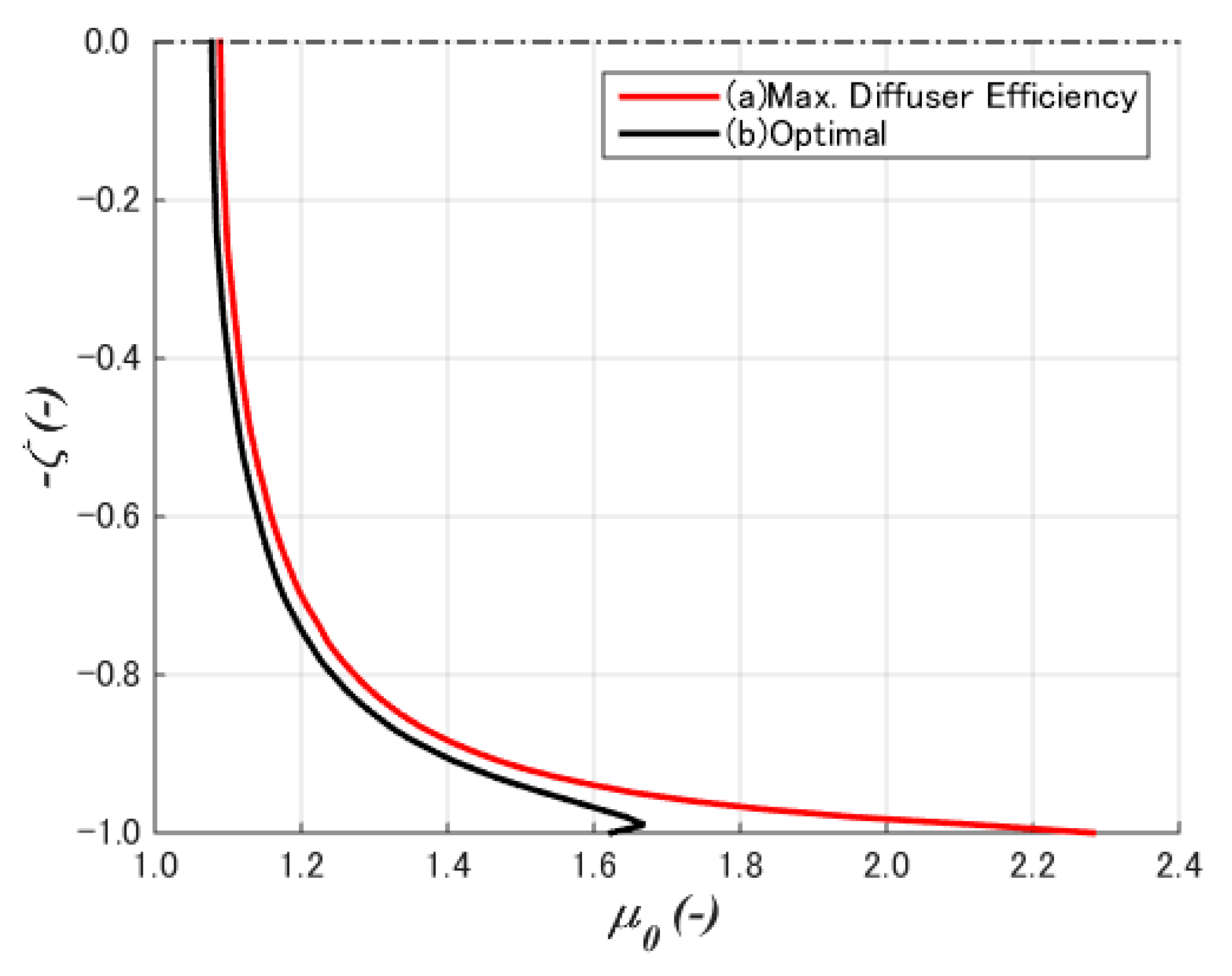
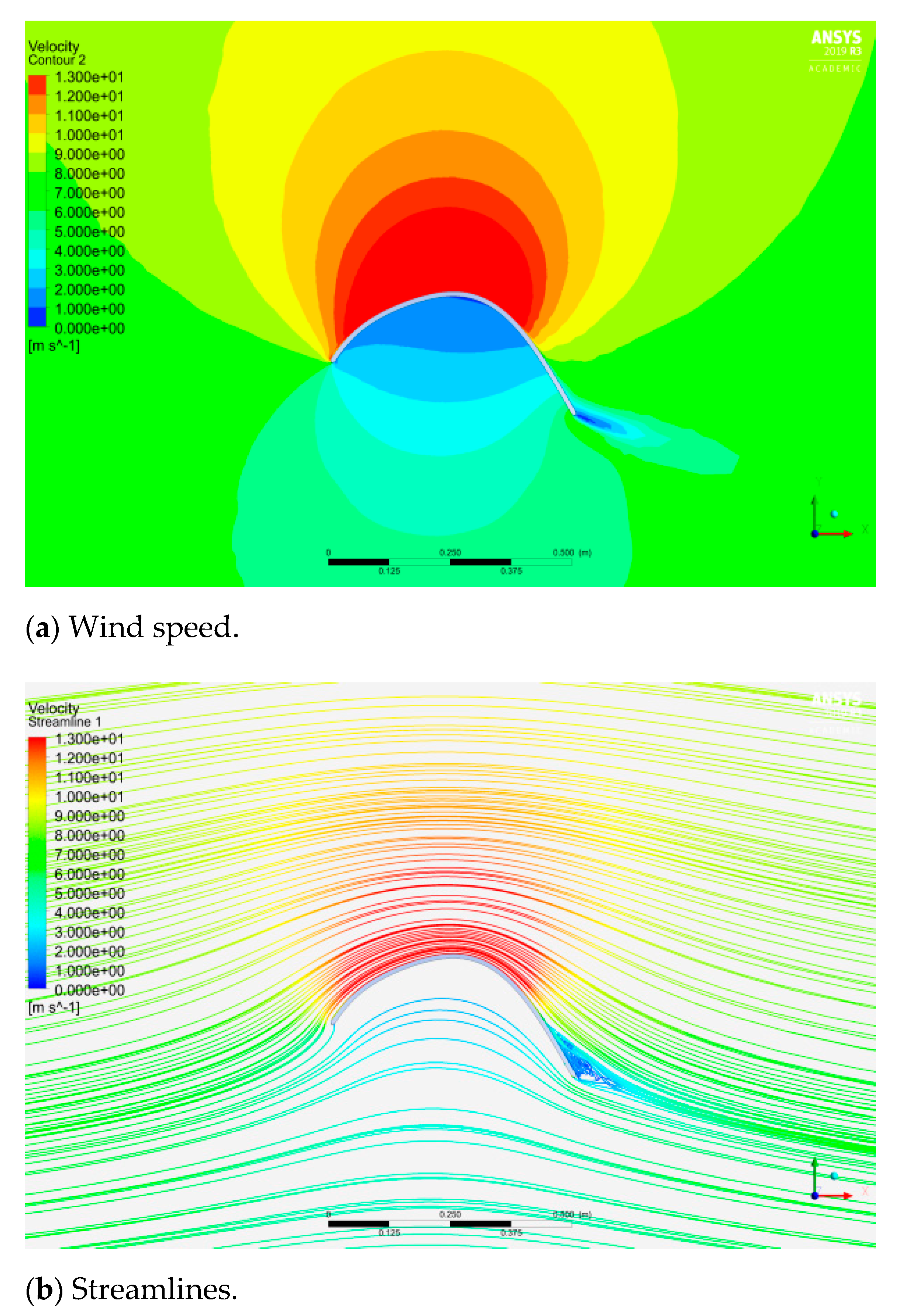
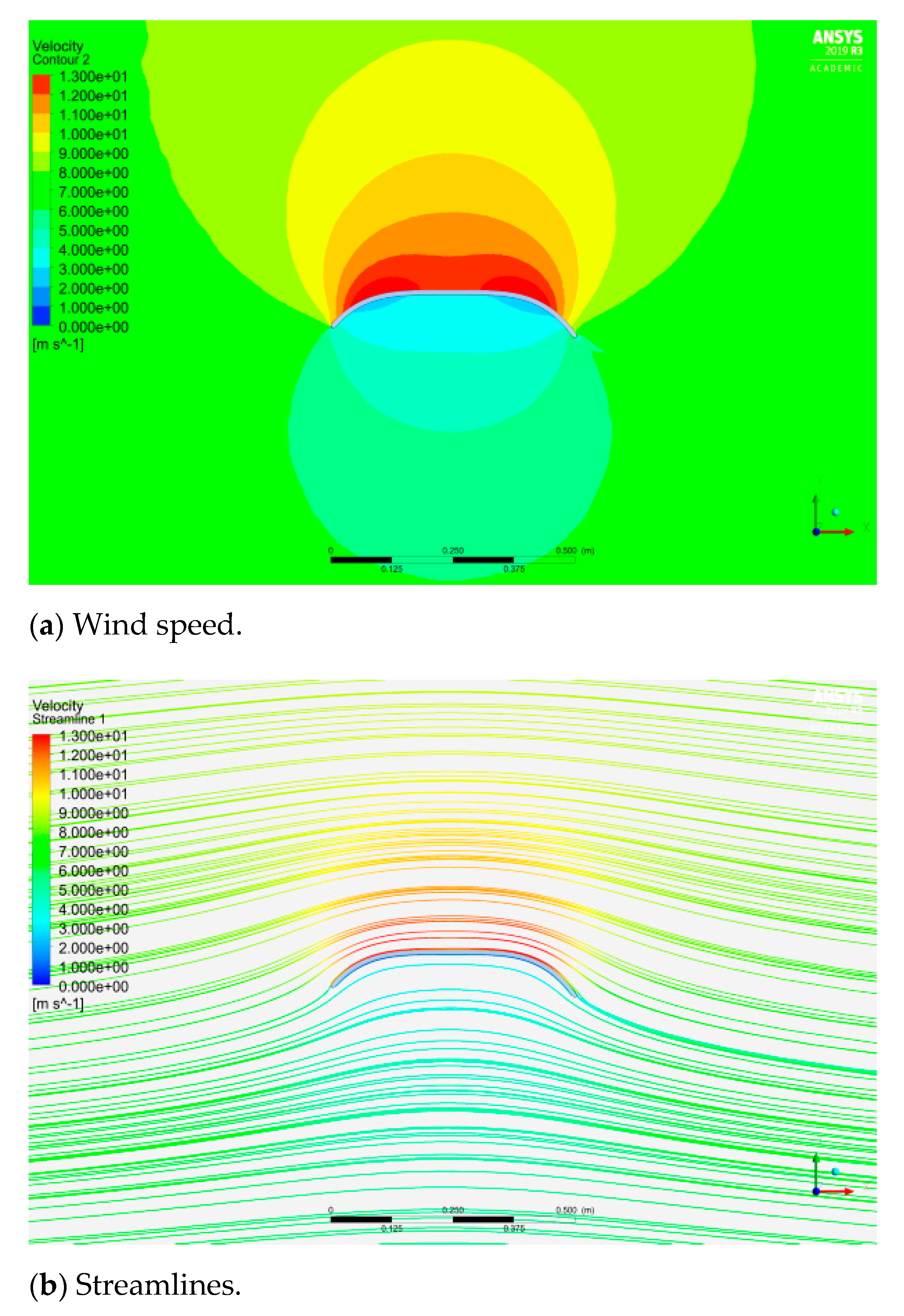
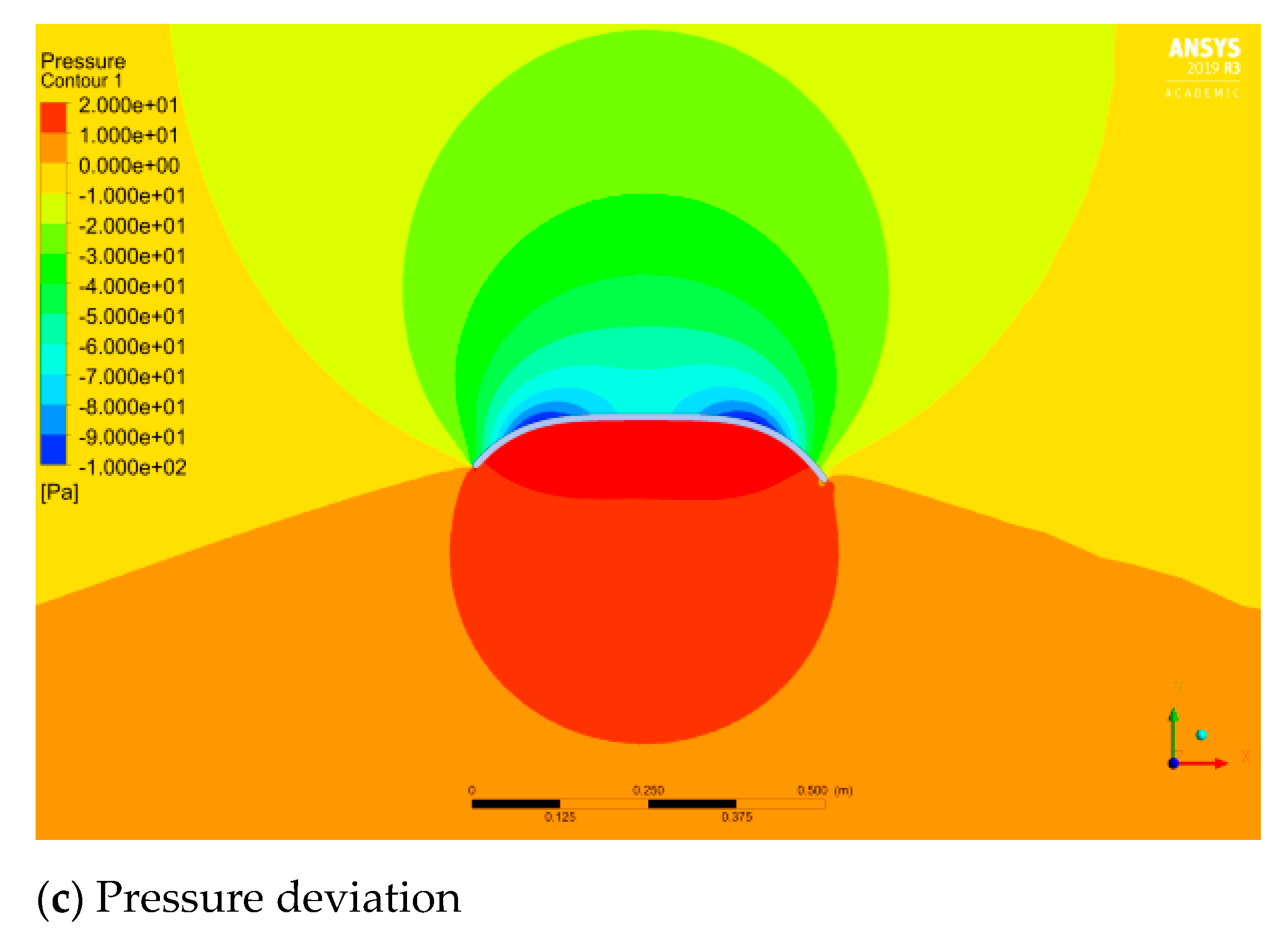
5.3. Wind Speed Distribution
5.4. Diffuser Efficiency (Speedup Ratio)
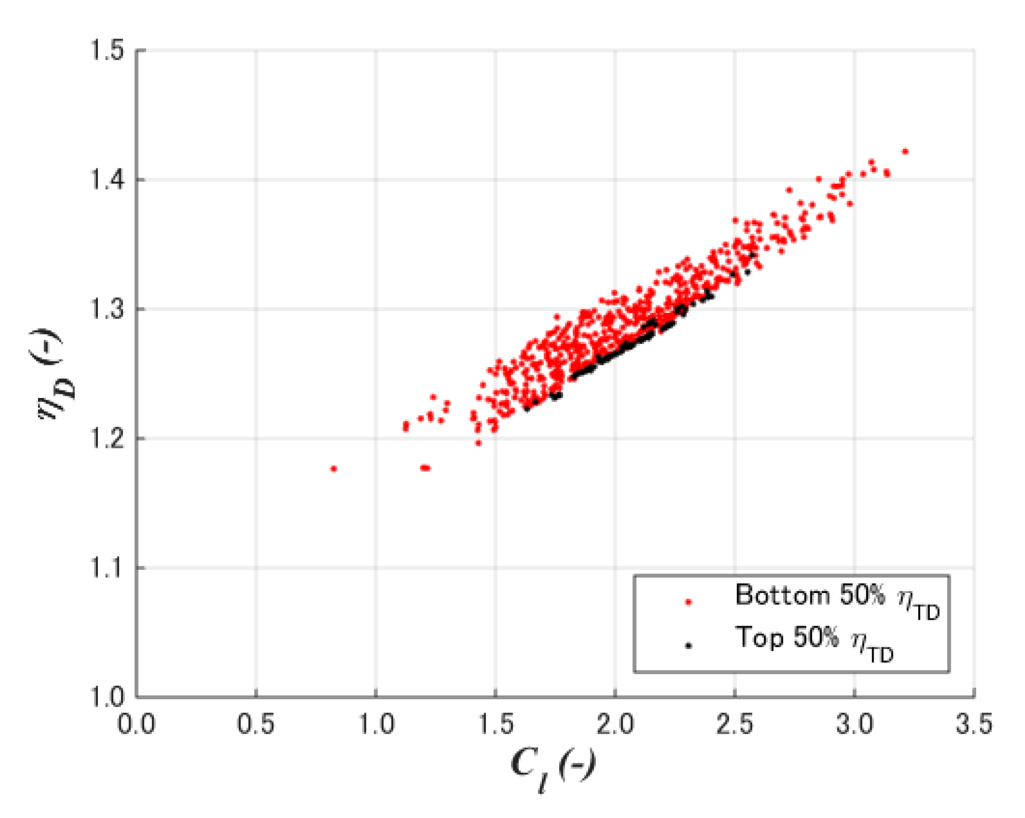
5.5. Diffuser Total Efficiency
6. Conclusions
- (1)
- An optimization method was developed using an axisymmetric two-dimensional CFD and a genetic algorithm. Here, the diffuser total efficiency, which is not affected by the axial and the tangential inductions by the rotor, was formulated as the index for the diffuser of DAWTs based on the generalized actuator disc model.
- (2)
- A case study of a 2% chord flat plate with a diameter chord length ratio of 0.1 and the crest position at 50% chord length showed the cross-sectional shapes of the maximum diffuser total efficiency is completely different from that of maximum speedup ratio. The former showed a flat top with large curvatures at the front rear of the diffuser, whereas the latter showed large camber as high-lift devices on airplane wings.
- (3)
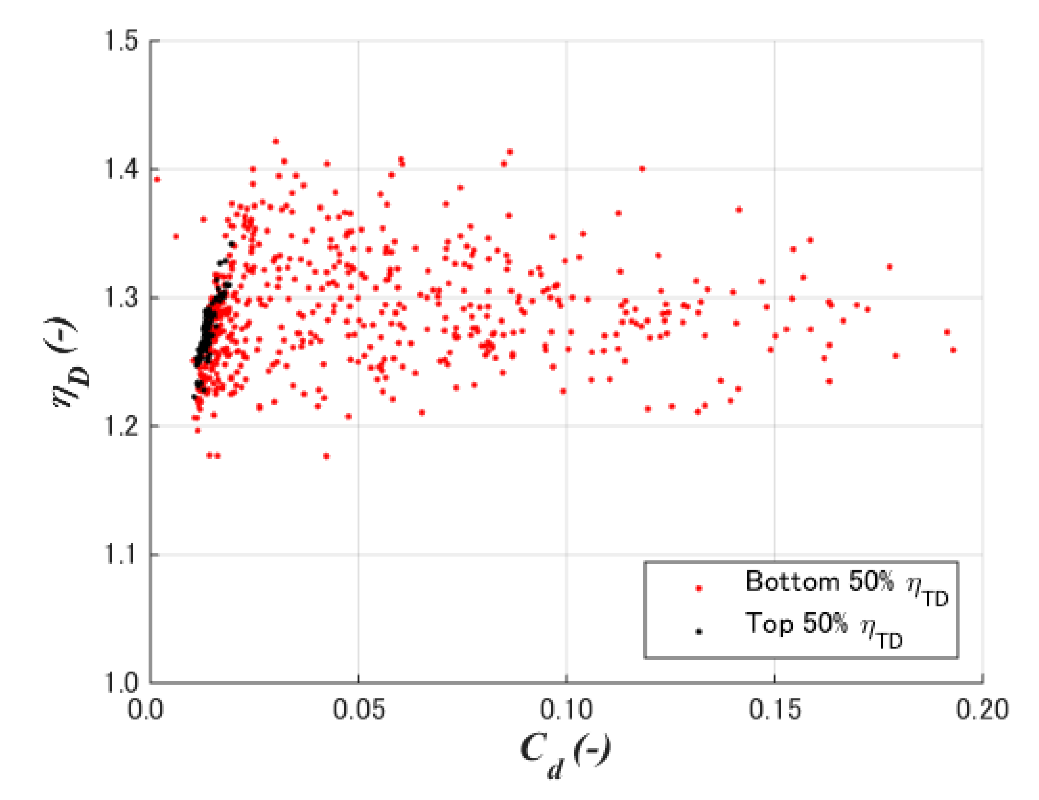
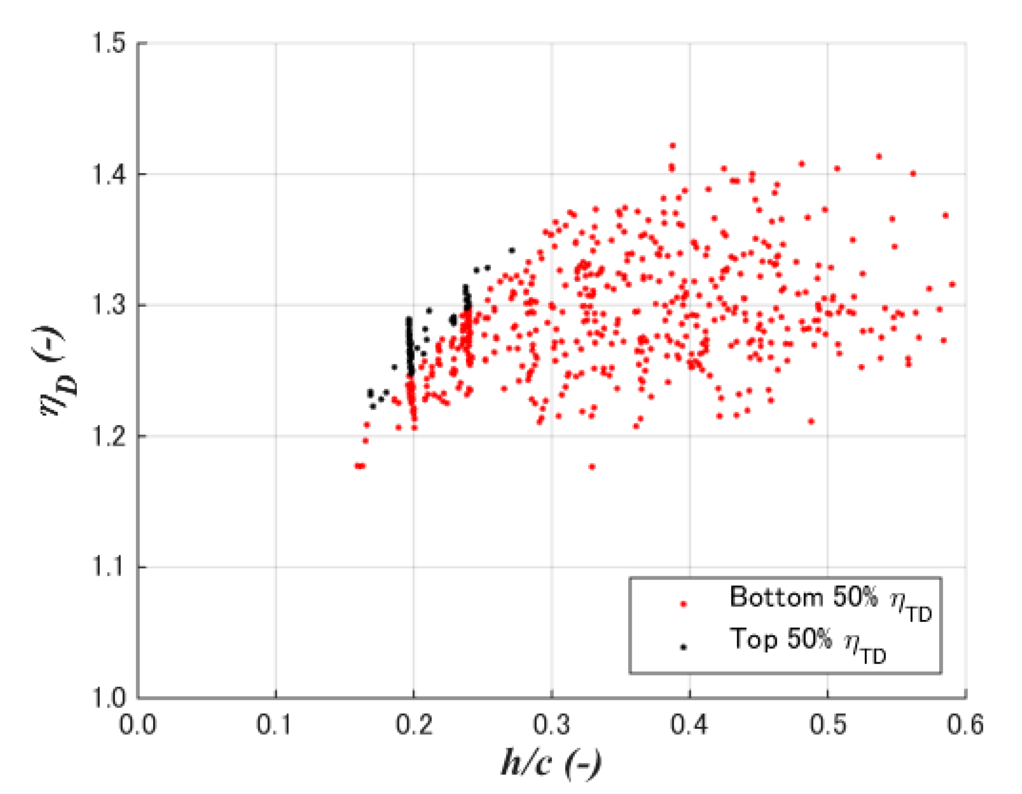
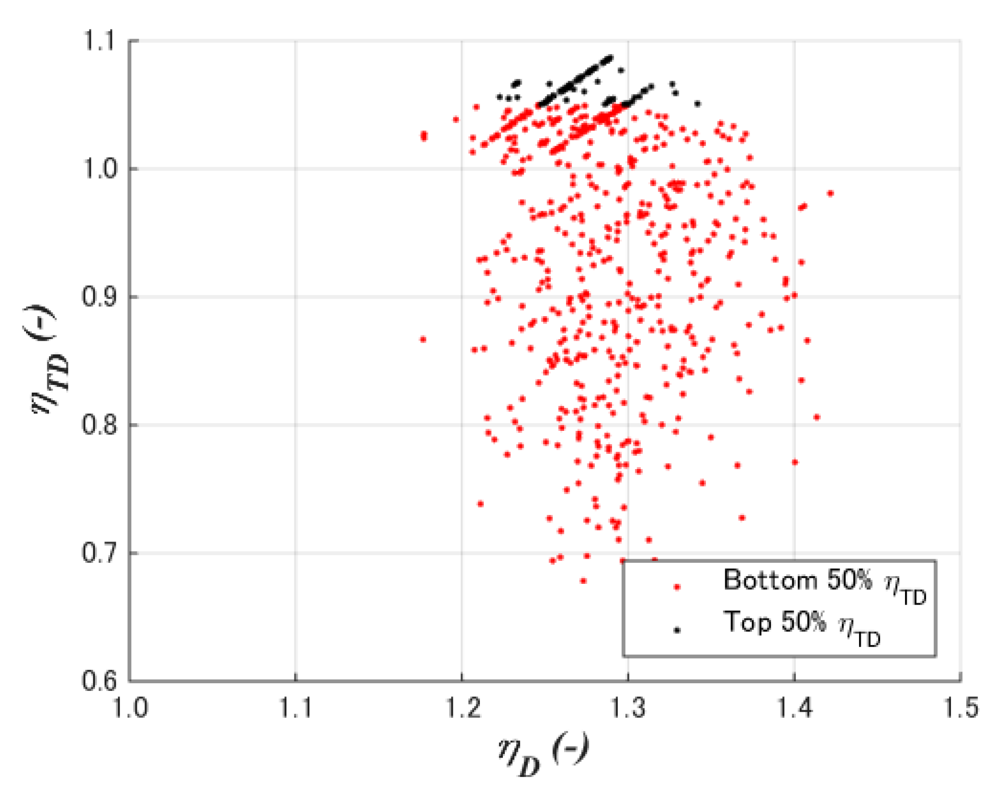
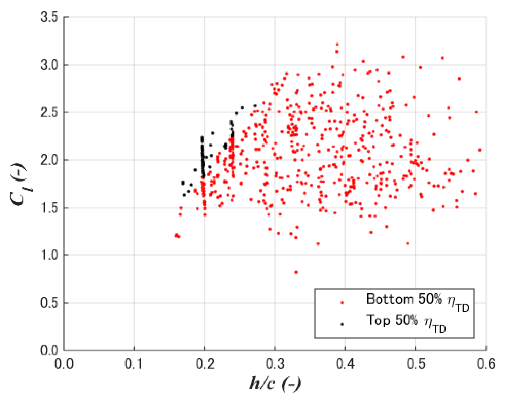
- The total diffuser efficiency of the case study was shown to be 1.087. Furthermore, 1392 (=48 population × 29 generations) CFD simulations resulted in the optimization process, where it was confirmed that the total diffuser efficiency appears under the condition of low-drag and high-lift coefficients with a 15–25% diffuser height-to-chord ratio.
- (1)
- The present result above was calculated under the conditions defined in this study. The crest position and the thickness-to-chord can be changed, and the range and order of the cross-section parameters can be expanded.
- (2)
- The present optimization method is applicable for other diffuser performance indexes. The present results by the total diffuser total efficiency will be compared with the optimization by other diffuser performance parameters as well as experiments.
- (3)
- In addition to the axisymmetric diffuser-alone optimization in the present study, the influence of tangential flow by the rotor, the blade-diffuser interaction, and yaw misalignment will be discussed.
- (4)
- Furthermore, the influences of the axial and the tangential inductions by the rotor, which are not considered in the present study, will be investigated.
Author Contributions
Funding
Institutional Review Board Statement
Informed Consent Statement
Data Availability Statement
Conflicts of Interest
Nomenclatures
| a | Diffuser induction factor. |
| a0 | Diffuser induction factor with no rotor induction. |
| c | Chord length of the diffuser section. |
| Cd | Drag coefficient of the diffuser section. |
| Cl | Lift coefficient of the diffuser section. |
| CP | Power coefficient base on the rotor area. |
| D | Rotor diameter or diffuser internal diameter. |
| fd | Diffuser section drag force, parallel to the wind. |
| fl | Diffuser section lift force, normal to the wind, positive to the diffuser center. |
| h | Height of the diffuser cross-section. |
| N | Order of the polynomial of the camber line. |
| R | Rotor radius. |
| r | Station radius on the rotor plane. |
| SR | Rotor area. |
| SD | Diffuser swept area. |
| T | Rotor thrust. |
| U | Free stream wind speed. |
| u | Longitudinal wind speed on the rotor plane. |
| x | Chord-wise position of the diffuser section. |
| yC | Camber height of the diffuser section. |
| y’C | Camber slope of the diffuser section. |
| αn | Coefficient of the polynomial of the cross-section camber. |
| ζ | Rotor station radius normalized by the rotor radius. |
| ηD | Diffuser efficiency. |
| ηTD | Diffuser total efficiency. |
| μ0 | Local speedup ratio, i.e., wind speed at the rotor normalized by the free stream wind speed. |
| ρ | Air density. |
Subscripts
| Cr | Crest of the diffuser section. |
| LE | Leading edge of the diffuser section. |
| TE | Trailing edge of the diffuser section. |
Abbreviations
| CFD | Computational Fluid Dynamics. |
| DAWT | Diffuser-Augmented Wind Turbine. |
| GA | Genetic Algorithm. |
| LE | Leading Edge. |
| TE | Trailing Edge. |
References
- Gipe, P. FloDesign-Ogin, Wind-Works, 22 May 2020. Available online: http://www.wind-works.org/cms/index.php?id=665 (accessed on 14 November 2020).
- Riamwind Improve Wind Power Generation Efficiency with Wind Lens, 9 May 2020. Available online: http://www.riamwind.co.jp/english/introduction.html (accessed on 14 November 2020).
- Gipe, P. Vortec, Wind-Works. Available online: http://www.wind-works.org/cms/index.php?id=662 (accessed on 14 November 2020).
- Ohya, Y.; Uchida, T.; Karasudani, T.; Hasegawa, M.; Kume, H. Numerical Studies of Flow around a Wind Turbine Equipped with a Flanged-Diffuser Shroud Using an Actuator-Disk Model. Wind Eng. 2012, 36, 455–472. [Google Scholar] [CrossRef]
- Ohya, Y.; Karasudani, T. A Shrouded Wind Turbine Generating High Output Power with Wind-lens Technology. Energies 2010, 3, 634–649. [Google Scholar] [CrossRef]
- Bontempo, R.; Manna, M. Diffuser Augmented Wind Turbines: Review and Assessment of Theoretical Models. Appl. Energy 2020, 280, 115867. [Google Scholar] [CrossRef]
- Betz, A. Energieumsetzungen in Venturidusen. Naturwissenschaften 1929, 17, 160–164. [Google Scholar] [CrossRef]
- Lilley, G.M.; Rainbird, W.J. A Preliminary Report on the Design and Performance of Ducted Windmills; Technical Report 102; Collage of Aeronautics of Cranfield University: Cranfield, UK, 1956. [Google Scholar]
- Van Bussel, G.J.W. The Science of Making More Torque from Wind: Diffuser Experiments and Theory Revisited. J. Phys. Conf. Ser. 2007, 75, 012010. [Google Scholar] [CrossRef]
- Jamieson, P. Innovation in Wind Turbine Design; John Wiley and Sons: Chichester, UK, 2011. [Google Scholar]
- Liu, Y.; Yoshida, S. An Extension of the Generalized Actuator Disc Theory for Aerodynamic Analysis of the Diffuser-Augmented Wind Turbines. Energy 2015, 93, 1852–1859. [Google Scholar] [CrossRef]
- Igra, O. Research and Development for Shrouded Wind Turbines. Energy Convers. 1981, 21, 13–48. [Google Scholar] [CrossRef]
- Oka, N.; Furukawa, M.; Yamada, K.; Kido, K. Aerodynamic Design for Wind-lens Turbine Using Optimization Technique. In Proceedings of the ASME 2013 Fluids Engineering Division Summer Meeting, FEDSM 2013, Incline Village, NV, USA, 7–11 July 2013. [Google Scholar]
- ANSYS. ANSYS Fluent: Canonsburg, PA, USA. 2019. Available online: https://www.ansys.com/ja-jp/products/fluids/ansys-fluent (accessed on 4 February 2021).




| Boundary | Distance from the Rotor Center | Boundary Conditions |
|---|---|---|
| Diffuser | 0.5 D, 5 c | Nonslip |
| Inlet | 4 D, 40 c | Wind Speed |
| Outlet | 5 D, 50 c | Ambient Pressure |
| Sides | 2 D, 20 c | Slip |
| Central angle | 1° | - |
| (A) Max. Diffuser Efficiency (Max. Speedup Ratio) | (B) Max. Diffuser Total Efficiency (Optimal) | |
|---|---|---|
| Diffuser Total Efficiency ηTD | 0.865575 | 1.086669 |
| Diffuser Efficiency ηD | 1.4617112 | 1.283966 |
| Average Speedup Ratio | 1.4617112 | 1.283966 |
| Lift Coefficient Cl | 5.37 | 3.42 |
| Drag Coefficient Cd | 0.0787 | 0.00451 |
| LE Position xCLE/c | 0.000000 | 0.000000 |
| Crest Position xCCr/c | 0.500000 | 0.500000 |
| TE Position xCTE/c | 1.000000 | 1.000000 |
| LE Height yCLE/c | 0.000000 | 0.000000 |
| Crest Height yCCr/c | 0.2814486 | 0.1444352 |
| TE Height yCTE/c | −0.2176434 | −0.0410022 |
| LE Slope y’CLE | 1.631496 | 1.176656 |
| Crest Slope y’CCr | 0.000000 | 0.000000 |
| TE Slope y’CTE | −1.693913 | −1.439804 |
Publisher’s Note: MDPI stays neutral with regard to jurisdictional claims in published maps and institutional affiliations. |
© 2021 by the authors. Licensee MDPI, Basel, Switzerland. This article is an open access article distributed under the terms and conditions of the Creative Commons Attribution (CC BY) license (http://creativecommons.org/licenses/by/4.0/).
Share and Cite
Yoshida, S.; Motoyama, M.; Jamieson, P.; Matsuoka, K. Diffuser Total Efficiency Using Generalized Actuator Disc Model and Its Maximization Method. Energies 2021, 14, 813. https://doi.org/10.3390/en14040813
Yoshida S, Motoyama M, Jamieson P, Matsuoka K. Diffuser Total Efficiency Using Generalized Actuator Disc Model and Its Maximization Method. Energies. 2021; 14(4):813. https://doi.org/10.3390/en14040813
Chicago/Turabian StyleYoshida, Shigeo, Masataka Motoyama, Peter Jamieson, and Koij Matsuoka. 2021. "Diffuser Total Efficiency Using Generalized Actuator Disc Model and Its Maximization Method" Energies 14, no. 4: 813. https://doi.org/10.3390/en14040813
APA StyleYoshida, S., Motoyama, M., Jamieson, P., & Matsuoka, K. (2021). Diffuser Total Efficiency Using Generalized Actuator Disc Model and Its Maximization Method. Energies, 14(4), 813. https://doi.org/10.3390/en14040813


