
Phase Current Measurement Method of Dual Inverter-Motor Drive System Using a Single DC Link Current Sensor


Abstract
:1. Introduction
2. Phase Current Measurement Method Using a Single DC Link Current Sensor
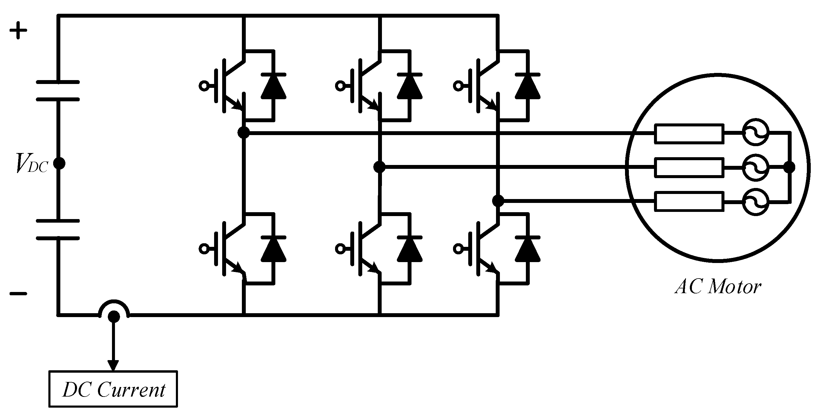
2.1. One Inverter-Motor System
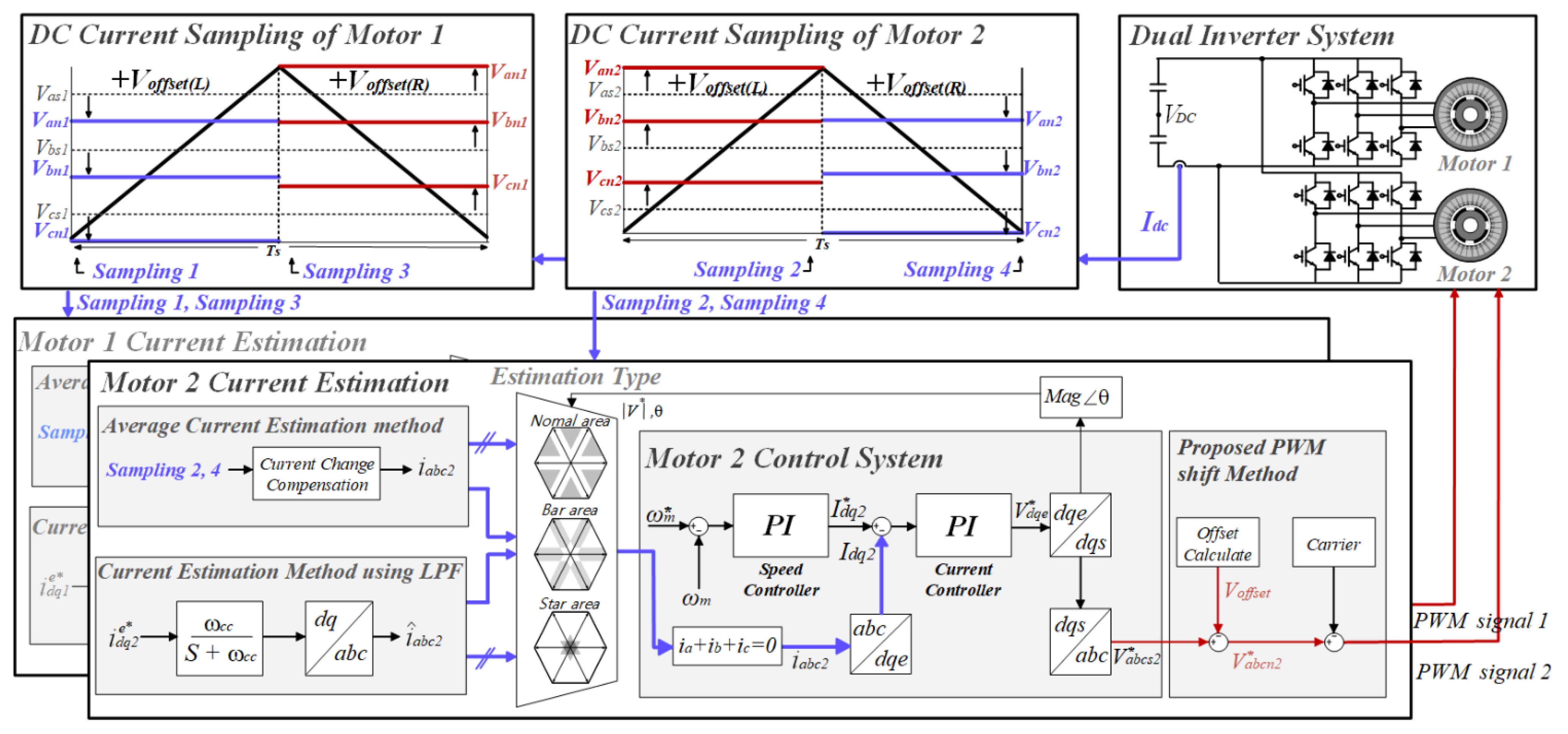
2.2. Dual Inverter-Motor Drive System
3. Proposed PWM Shift Method for Phase Current Measurement in a Dual Inverter-Motor Drive System
3.1. Securing Measuring Time by Offset Voltage
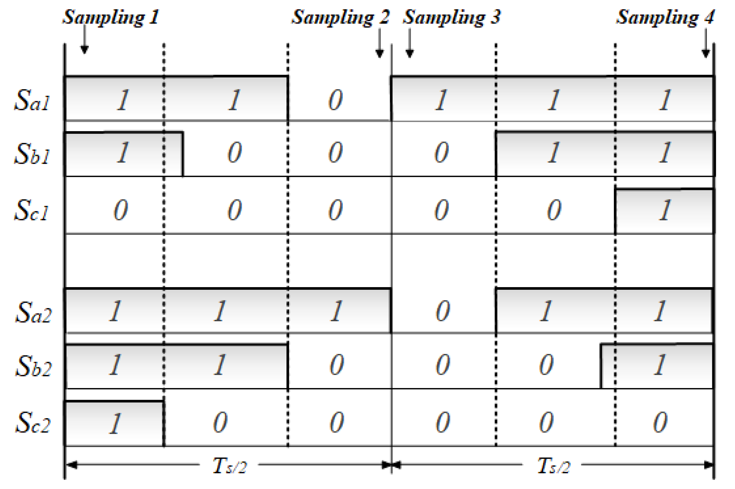
3.2. Phase Current Sampling Using PWM Shift Method
3.3. Modifiable Reference Voltage Applied with the Proposed Method
4. Proposed Phase Current Reconstruction Method
4.1. The Need for Average Current Estimation
4.2. The Need for Average Current Estimation
4.3. The Need for Average Current Estimation
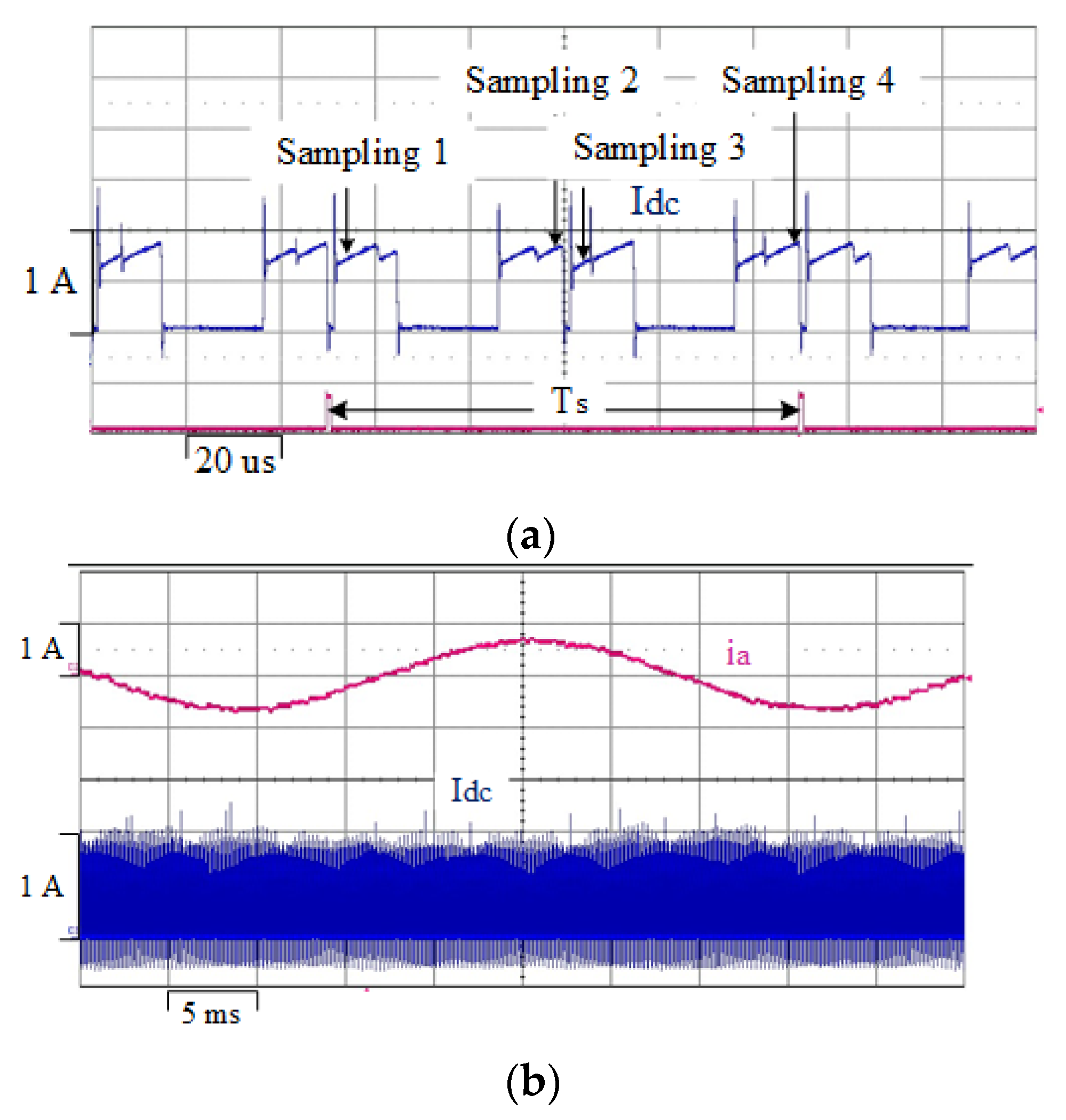
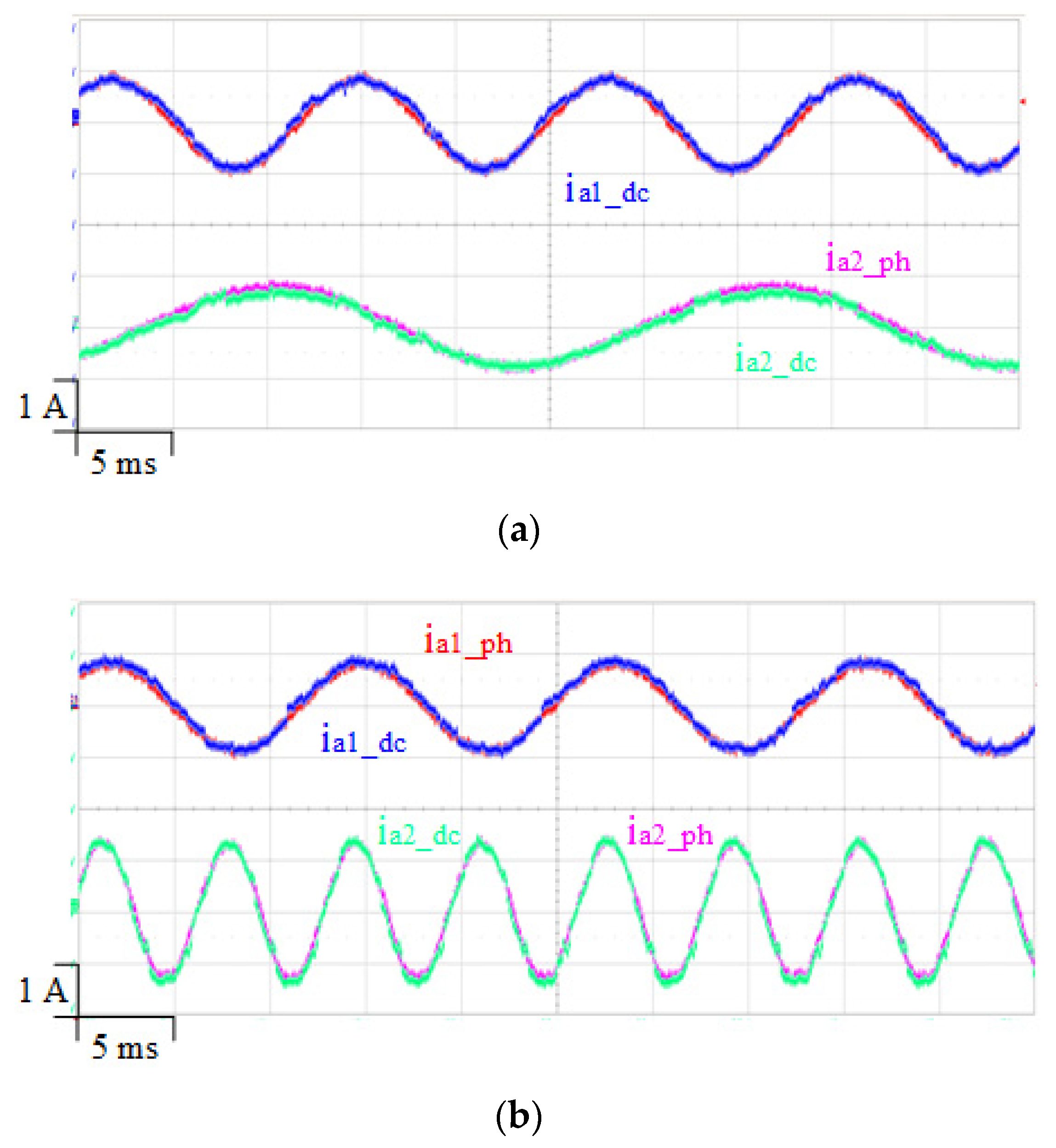
5. Experimental Results
6. Conclusions
Author Contributions
Funding
Institutional Review Board Statement
Informed Consent Statement
Data Availability Statement
Conflicts of Interest
References
- Kim, H.D.; Perry, A.T.; Ansell, P.J. A review of Distributed Electric Propulsion Concepts for Air Vehicle Technology. In Proceedings of the 2018 AIAA/IEEE EATS, Cincinnati, OH, USA, 12–14 July 2018. [Google Scholar]
- Shamiyeh, M.; Rothfeld, R.; Hornung, M.A. Performance Benchmark of Recent Personal Air Vehicle Concepts for Urban Air Mobility. In Proceedings of the 31th Congress of the International Council of the Aeronautical Sciences, Belo Horizonte, Brazil, 9–14 September 2018. [Google Scholar]
- Song, W.; Pei, X.; Xi, J.; Zeng, X. A Novel Helical Superconducting Fault Current Limiter for Electric Propulsion Aircraft. IEEE Trans. Transp. Electrif. 2021, 7, 276–286. [Google Scholar] [CrossRef]
- Sarlioglu, B.; Morris, C.T. Morries. More Electric Aircraft: Review, Challenges, and Opportunities for Commercial Transport Aircraft. IEEE Trans. Transp. Electrif. 2015, 1, 54–64. [Google Scholar] [CrossRef]
- Rosero, J.A.; Ortega, J.A.; Aldabas, E.; Romeral, L.A. Moving Towards a More Electric Aircraft. IEEE Aerosp. Electron. Syst. Mag. 2007, 22, 3–9. [Google Scholar] [CrossRef] [Green Version]
- Ye, H.; Emadi, A. A Six-Phase Current Reconstruction Scheme for Dual Traction Inverters in Hybrid Electric Vehicles with a Single DC-Link Current Sensor. IEEE Trans. Veh. Technol. 2014, 63, 3085–3093. [Google Scholar] [CrossRef]
- Van Der Broeck, H.W.; Skudelny, H.C.; Stanke, G.V. Analysis and Realization of a Pulsewidth Modulator Based on Voltage Space Vectors. IEEE Trans. Ind. Appl. 1988, 24, 142–150. [Google Scholar] [CrossRef]
- Gan, C.; Wu, J.; Wang, N.; Hu, Y.; Cao, W.; Yang, S. Independent Current Control of Dual Parallel SRM Drive Using a Public Current Sensor. IEEE/ASME Trans. Mechatron. 2017, 1, 392–401. [Google Scholar] [CrossRef] [Green Version]
- Schiedermeier, M.; Rettner, C.; Heilmann, M.; Schneider, F.; Marz, M. Interference of automotive HV-DC-systems by traction voltage-source-inverters (VSI). In Proceedings of the 2019 IEEE Transportation Electrification Conference, Bengaluru, India, 17–19 December 2019. [Google Scholar]
- Liu, T.; Fadel, M. An Efficiency-Optimal Control Method for Mono-Inverter Dual-PMSM Systems. IEEE Trans. Ind. Appl. 2018, 2, 1737–1745. [Google Scholar] [CrossRef]
- Wang, X.; Wang, Z.; Xu, Z.; He, J.; Zhao, W. Diagnosis and Tolerance of Common Electrical Faults in T-Type Three-Level Inverters Fed Dual Three-Phase PMSM Drives. IEEE Trans. Power Electron. 2020, 2, 1753–1769. [Google Scholar] [CrossRef]
- Ha, J.I. Voltage Injection Method for Three-Phase Current Reconstruction in PWM Inverters Using a Single Sensor. IEEE Trans. Power Electron. 2009, 24, 767–775. [Google Scholar]
- Park, C.-H.; Kim, D.-Y.; Yeom, H.-B.; Son, Y.-D.; Kim, J.-M. A Current Reconstruction Strategy Following the Operation Area in a 1-Shunt Inverter System. Energies 2019, 12, 1423. [Google Scholar] [CrossRef] [Green Version]
- Wang, W.; Yan, H.; Xu, Y.; Zou, J.; Zhang, X.; Zhao, W.; Buticchi, G.; Gerada, C. New Three-Phase Current Reconstruction for PMSM Drive With Hybrid Space Vector Pulsewidth Modulation Technique. IEEE Trans. Power Electron. 2021, 1, 662–673. [Google Scholar] [CrossRef]
- Lee, W.-C.; Hyun, D.-S.; Lee, T.-K. A Novel Control Method for Three-Phase PWM Rectifiers Using a Single Current Sensor. IEEE Trans. Power Electron. 2000, 15, 861–870. [Google Scholar]
- Lu, H.; Cheng, X.; Qu, W.; Sheng, S.; Li, Y.; Wang, Z. A Three-Phase Current Reconstruction Technique Using Single DC Current Sensor Based on TSPWM. IEEE Trans. Power Electron. 2014, 3, 1542–1550. [Google Scholar]
- Lin, Y.-K.; Lai, Y.-S. PWM Technique to Extend Current Reconstruction Range and Reduce Common-Mode Voltage for Three-Phase Inverter using DC-link Current Sensor Only. In Proceedings of the 2011 IEEE ECCE, Phoenix, AZ, USA, 17–22 September 2011. [Google Scholar]
- Lai, Y.-S.; Lin, Y.-K.; Chen, C.-W. New Hybrid Pulsewidth Modulation Technique to Reduce Current Distortion and Extend Current Reconstruction Range for a Three-Phase Inverter Using Only DC-link Sensor. IEEE Trans. Power Electron. 2013, 28, 1331–1337. [Google Scholar] [CrossRef]
- Saritha, B.; Janakiraman, P.A. Sinusoidal Three-Phase Current Reconstruction and Control Using a DC-Link Current Sensor and a Curve-Fitting Observer. IEEE Trans. Ind. Electron. 2007, 54, 2657–2664. [Google Scholar] [CrossRef]
- Kim, K.-S.; Yeom, H.-B.; Ku, H.-K.; Kim, J.-M.; Im, W.-S. Current Reconstruction Method with Single DC-Link sensor based on the PWM inverter and AC motor. In Proceedings of the IEEE ECCE, Pittsburgh, PA, USA, 14–18 November 2014. [Google Scholar]
- Kim, H.-J.; Kim, J.-M.; Kim, J.-M. Current measurement and control method of HVAC integration system through DC link single current sensor. J. Power Electron. 2020, 20, 1243–1249. [Google Scholar] [CrossRef]
- Bing, Z.; Du, X.; Sun, J. Control of Three-Phase PWM Rectifiers Using a Single DC Current Sensor. IEEE Trans. Power Electron. 2010, 26, 1800–1808. [Google Scholar] [CrossRef]
- Green, T.C.; Williams, B.W. Derivation of motor line-current waveforms from the DC-link current of an inverter. IEE Proc. 1989, 136, 196–204. [Google Scholar] [CrossRef]
- Chung, D.-W.; Kim, J.-S.; Sul, S.-K. Unified voltage modulation technique for real-time three-phase power conversion. IEEE Trans. Ind. Appl. 1998, 34, 374–380. [Google Scholar] [CrossRef]


| Switching State | Active Voltage Vector | Zero Voltage Vector | |||||
|---|---|---|---|---|---|---|---|
| (100) | (110) | (010) | (011) | (001) | (101) | (000) (111) | |
| iDC | ia | −ic | ib | −ia | ic | −ib | - |
| Sector | Inverter 1 | Inverter 2 | ||
|---|---|---|---|---|
| Sampling 1 | Sampling 3 | Sampling 2 | Sampling 4 | |
| 1 | −ic1 | ia1 | ia2 | −ic2 |
| 2 | −ic1 | ib1 | ib2 | −ic2 |
| 3 | −ia1 | ib1 | ib2 | −ia2 |
| 4 | −ia1 | ic1 | ic2 | −ia2 |
| 5 | −ib1 | ic1 | ic2 | −ib2 |
| 6 | −ib1 | ia1 | ia2 | −ib2 |
| Switching State | Slope of Phase a | Slope of Phase b | Slope of Phase c |
|---|---|---|---|
| 000 | |||
| 001 | |||
| 010 | |||
| 011 | |||
| 100 | |||
| 101 | |||
| 110 | |||
| 111 |
| Sampling Current | Generalized Equation of Estimation Average Current |
|---|---|
| 1 | |
| 2 | |
| 3 | |
| 4 |
| Motor | Inverter | ||
|---|---|---|---|
| Pole | 10 | DC link voltage | 24 V |
| Rated power | 30 W | Rated current | 2.1 A |
| Stator resistance | 1.35 Ω | Turn-on delay | 17 ns |
| Stator inductance | 542.5 uH | Turn-off delay | 100 ns |
| Back-EMF constant | 0.0237 V/wm | Dead Time | 1.2 μs |
Publisher’s Note: MDPI stays neutral with regard to jurisdictional claims in published maps and institutional affiliations. |
© 2021 by the authors. Licensee MDPI, Basel, Switzerland. This article is an open access article distributed under the terms and conditions of the Creative Commons Attribution (CC BY) license (https://creativecommons.org/licenses/by/4.0/).
Share and Cite
Hwang, S.-I.; Cho, S.-H.; Jung, J.-H.; Kim, J.-M. Phase Current Measurement Method of Dual Inverter-Motor Drive System Using a Single DC Link Current Sensor. Energies 2021, 14, 5626. https://doi.org/10.3390/en14185626
Hwang S-I, Cho S-H, Jung J-H, Kim J-M. Phase Current Measurement Method of Dual Inverter-Motor Drive System Using a Single DC Link Current Sensor. Energies. 2021; 14(18):5626. https://doi.org/10.3390/en14185626
Chicago/Turabian StyleHwang, Seon-Ik, Seong-Hyeon Cho, Jun-Hyung Jung, and Jang-Mok Kim. 2021. "Phase Current Measurement Method of Dual Inverter-Motor Drive System Using a Single DC Link Current Sensor" Energies 14, no. 18: 5626. https://doi.org/10.3390/en14185626
APA StyleHwang, S.-I., Cho, S.-H., Jung, J.-H., & Kim, J.-M. (2021). Phase Current Measurement Method of Dual Inverter-Motor Drive System Using a Single DC Link Current Sensor. Energies, 14(18), 5626. https://doi.org/10.3390/en14185626