Article

Including Heat Balance When Designing the Energy System of Fuel Cell-Powered AUVs

1
Applied Electrochemistry, School of Engineering Sciences in Chemistry, Biology and Health, KTH Royal Institute of Technology, 100 44 Stockholm, Sweden
2
Naval Architecture, School of Engineering Sciences, KTH Royal Institute of Technology, 100 44 Stockholm, Sweden
*
Author to whom correspondence should be addressed.
Energies 2021, 14(16), 4920; https://doi.org/10.3390/en14164920
Submission received: 14 July 2021 / Revised: 9 August 2021 / Accepted: 10 August 2021 / Published: 11 August 2021

Abstract

:
Fuel cell-powered Autonomous Underwater Vehicles (AUVs) represent a growing area of research as fuel cells can increase their endurance. Fuel cells consume hydrogen and oxygen to generate electricity. Typically, the fuel cell generates as much heat as electrical energy, and heat management becomes a crucial parameter when designing AUVs. For underwater applications, there is a need to store both gases and several types of storage units with different characteristics exist which have impacts on the energy density and heat behavior. This study aims at including the heat properties of the storage units in the design process of fuel cell-powered AUVs. A heat balance over the energy system of an AUV is calculated for each combination of hydrogen and oxygen storage units. In addition, a multi-criteria decision-making analysis is conducted, considering the calculated total heat, the specific energy, the energy density and the volumetric mass of each combination of storage units as criteria, enabling a comparison and ranking them using two objective criteria weighting methods. Results show that the fuel cell is the major contributor to the heat balance, and that the combinations of liquid oxygen with liquid or compressed hydrogen can be relevant and suitable for underwater applications.

1. Introduction

Fuel cell-powered Autonomous Underwater Vehicles (AUVs) represent a growing area of research interest. The use of a hydrogen fuel cell can increase significantly the energy content in the AUV, and therefore its endurance [1,2,3]. It was demonstrated that for missions longer than a few hours, volume-optimized hybrid fuel cell/battery systems are more relevant for AUVs than full battery systems, as they combine the high energy density of fuel cells and the power flexibility of batteries [4]. Since the late 90s, several projects have demonstrated the capabilities of low temperature fuel cell-powered AUVs using various hydrogen and oxygen storage units, fuel cells and batteries [5,6,7,8]. Long-range missions over 1000 km were performed. In a more recent project, the Canadian fuel cell-powered AUV, named Solus-LR, is currently under development [9]. It has a hybrid power system composed of a proton-exchange membrane fuel cell (PEMFC) and a Li-ion battery pack. Hydrogen and oxygen for the fuel cell are stored in high pressure vessels. Its current range is 2000 km, and the goal is to extend it up to 4000 km. Despite several successful projects, there are as of yet no commercial fuel cell-powered AUVs available on the market.
A fuel cell consumes hydrogen and oxygen to produce water, electricity and heat [10]. Typically, the electrical energy efficiency of the fuel-cell system is 40–60%, which means that roughly as much heat as electric power is generated [1]. How to handle this heat, and its impact on the design of the AUV energy system, is a question often raised. For underwater applications both hydrogen and oxygen for the fuel cell need to be stored in the vehicle. Different storage solutions have different materials, chemistries and heat properties; therefore, the choice of storage has a direct impact not only on the final volume and weight of the energy system, but also on the heat management. Strategies and guidelines about the energy-system design of fuel cell-powered AUVs are found in the literature [1,4,11,12]. However, they focus on the energy content of the hybrid system, while thermal properties of the components and the total heat balance of the energy system are not considered. The goal of this study is to fill this gap by including the heat management in the design process, alongside the energy density and the specific energy of the power system, and to perform an objective comparison of using different hydrogen and oxygen storage units for fuel cell-powered AUVs.
Each type of hydrogen and oxygen storage has its specific thermal properties. For example, in some cases, heat needs to be applied in order to maintain the release of reactant and, in some other cases, heat needs to be removed in order to keep the release process under control. In addition, heat is generated by the fuel cell. Therefore, good heat management is important to optimize the efficiency of fuel cell-powered vehicles [13,14]. There are several examples of thermal management of the hybrid system for vehicles, but these are only for land vehicles such as cars and trucks. Pfeifer et al. couple their 1 kW high-temperature PEMFC with a hydride hydrogen tank [15]. For such tanks, the release of hydrogen is limited by the possible heat supplied to them. The heat generated by the fuel cell is thus used to keep the tank at the desired temperature and maintain the release of hydrogen. A similar approach was investigated for an electric vehicle using a 6 kW high-temperature PEMFC as a range-extender, combined with metal-hydride storage [16]. In that study, a thermal controller was developed based on various scenarios for electric-car operations. The thermal-management system was found to be capable of cooling the fuel cell and maintain the release of hydrogen from the metal-hydride tank at the same time, using several heat exchangers. However, in the case of an AUV, the available volume and weight are limited, which makes it complicated to add subcomponents, such as heat exchangers or heat pumps, in order to reuse the heat. For the AUV, the final buoyancy is also a crucial parameter that must be considered when designing and selecting components for the energy system [4,11].
The energy system considered in this study includes a fuel cell stack, an oxygen storage unit, a hydrogen storage unit and a battery pack, and is intended for an underwater vehicle with base- and peak power of 900 W and 1.8 kW, respectively, capable of performing a 50 h mission. Here, the heat properties of the different storage units and power sources will be included in the design process of the energy system by combining a thermodynamic approach with a decision-making analysis. An estimation of the total heat generated by the energy system is provided for several types of hydrogen and oxygen storage unit. As with the energy density, specific energy and volumetric mass of the hybrid fuel cell/battery system, the calculated total heat becomes a criterion to evaluate and select the most suitable energy system for AUVs. In order to compare the different storage solutions according to these quantitative criteria, an objective Multi-Criteria Decision-Making (MCDM) analysis is carried out. A time analysis is also carried out to evaluate the impact of the mission duration on the result and therefore, on the selection of hydrogen and oxygen storage units.

2. Overview of Storage Units Considered in This Study

Three types of hydrogen and three types of oxygen storage units are considered in this study. In this section, the general principle of each system, as well as some important properties, are briefly presented.

2.1. Hydrogen Storage Units

Compressed hydrogen (hereafter: Comp H2) is the simplest and cheapest solution for hydrogen storage. No pre-processing of hydrogen is needed [5,17,18,19,20]. High pressure, up to 700 bar, is applied by a compressor. For commercial fuel cell cars, the hydrogen tank is usually at either 350 or 700 bar. When hydrogen needs to be used, a pressure reducer after the output of the tank is often necessary. The weight of compressed-hydrogen tanks varies with the material used, and thickness of the wall increases with the storage pressure. Originally, the tanks were composed of metals, which makes the storage relatively cheap, but also heavy and only suitable for stationary applications. The main challenge is therefore to drastically reduce the weight of the storage, and today composite materials are being developed for this type of gas storage. There are four standard types of cylinders available for compressed hydrogen [21]. In this study, a light-weight composite cylinder is considered.
Rechargeable metal hydrides (hereafter: MH) are metal alloys that can reversibly react with hydrogen [5,21,22,23,24]. The adsorption of hydrogen on the metal alloy ( M ) is possible at the proper conditions of temperature, heat and pressure. The adsorption can be described by the following chemical reaction [25]:
M + x 2 H 2 = MH x + heat
The adsorption reaction is exothermic, i.e., it generates heat and may require heat removal. Conversely, desorption of hydrogen is an endothermic reaction [26]. Heat must therefore be applied to the metal alloy in order to maintain the desorption of hydrogen. The volumetric density of metal hydrides is high; however, their gravimetric density is very low, making the storage heavy. Metal hydrides are also sensitive to several contaminants such as water, carbon monoxide and oxygen.
Liquid hydrogen (hereafter: LH2) has a higher energy density than compressed hydrogen gas, although it is still relatively low. Hydrogen reaches liquid state at its boiling point of 21 K and then has a density of 71 g/L at atmospheric pressure [19,21]. Given its low boiling temperature, liquid hydrogen must be stored in cryogenic Dewars [5]. The enthalpy of vaporization of liquid hydrogen is 904 J/mol [27]. The vaporization process of hydrogen is spontaneous due to the heat transfer from the surrounding environment to the system. As a result, the spontaneous evaporation rate must be kept lower than the hydrogen consumption of the fuel cell, in order to keep the system stable and not wasting hydrogen [28]. Liquid hydrogen is complicated to handle; indeed, boil-off losses can happen during both refueling and storage of liquid hydrogen [21,29]. In addition, the liquefaction process of hydrogen is energy intensive and expensive [30].

2.2. Oxygen Storage Units

In most fuel cell-powered vehicles, the oxygen is taken directly from ambient air, with no need for storage. Oxygen tanks for vehicle applications are therefore not as developed as the hydrogen tanks. However, several solutions exist and have different properties.
Compressed oxygen tanks (hereafter: Comp O2) are similar to compressed hydrogen tanks [28]. It is the simplest oxygen-storage solution in terms of delivery mechanism. Compressed oxygen up to 690 bar can be found [5], but is typically at 153 bar for automotive applications. As for the compressed-hydrogen tanks, the thickness of the wall increases with the storage pressure. In this study, the compressed-oxygen gas is stored in light aluminum cylinders.
Liquid oxygen (hereafter: LOX) is considered to be the optimal solution for volume-limited space applications since it is very light and compact [5]. The boiling point of oxygen is 90 K [31] and the enthalpy of vaporization is 6820 J/mol [32]. The vaporization of oxygen occurs spontaneously due to the heat flow from the surrounding environment to the system. However, LOX is hazardous to handle and losses due to boil-off of oxygen are also likely to happen when refueling the tank.
Oxygen can also be stored in chemical form, e.g., in hydrogen peroxide H2O2, nitrogen tetroxide N2O4, and sodium superoxide (Na2O2) [28]. These storage solutions are relatively simple but they are sensitive to oxidization. In some cases, the reaction cannot be stopped once the oxygen has started to be released, which can be an issue for varying power load. The use of hydrogen peroxide (hereafter: H2O2) for fuel cells is a growing area of research interest [33,34], and will be further investigated in this study. The oxygen is released in a (thermally or catalytically induced) exothermic chemical reaction, as described in Equation (2). The enthalpy of the reaction forming oxygen is −108 kJ/mol [35].
2 H 2 O 2 = 2 H 2 O + O 2 + heat

2.3. Summary of Hydrogen and Oxygen Storage Characteristics

The choice of hydrogen- and oxygen storage solutions is crucial when designing fuel cell-powered AUVs. Each storage has advantages and disadvantages that need to be considered. Some storage units are more suitable for stationary applications while others are indicated for vehicle applications. Table 1 summarizes the different properties of the described hydrogen and oxygen storage solutions.

3. Methodology

To include heat management when comparing hybrid battery/fuel cell systems for AUVs, heat calculations are in this study combined with a multi-criteria decision-making process, and applied on a case study.

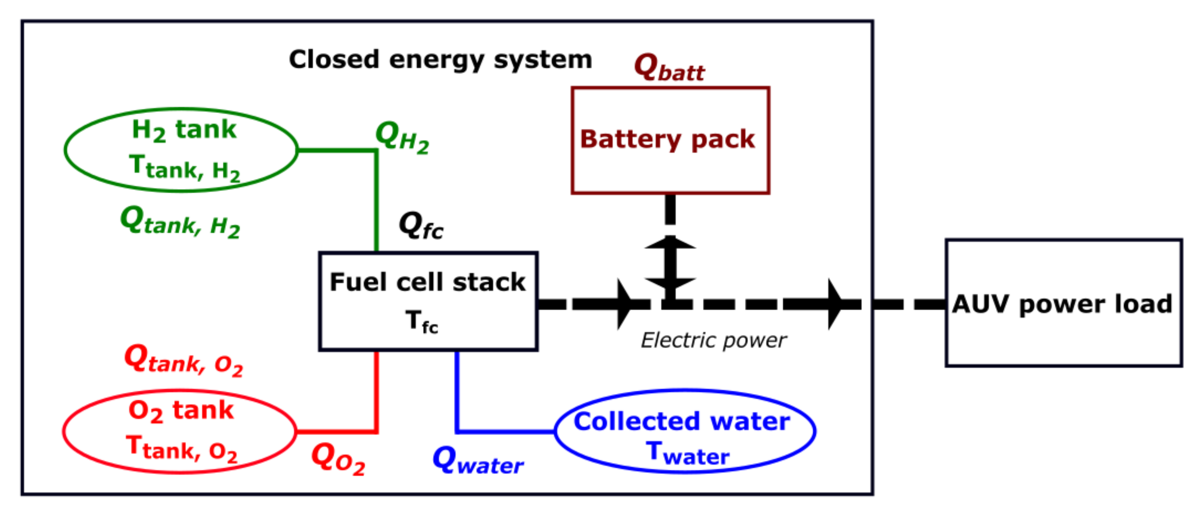
3.1. Heat Calculations

When estimating the total heat of the energy system, it is assumed to be isolated from the rest of the AUV components and in a closed environment. It is composed of the fuel cell stack, the battery pack, the hydrogen and oxygen storages. The total heat needed or generated by the energy system, Q t o t , is calculated (Equation (3)) as the sum of the heats:
Q t o t   = Q t a n k ,     H 2 + Q t a n k ,     O 2 + Q H 2 + Q O 2 + Q f c + Q b a t t + Q w a t e r
  • Of reactant release from the tank: Q t a n k
  • Needed to heat the gas up to the fuel cell temperature: Q i
  • Released by the fuel cell: Q f c
  • Due to the battery pack: Q b a t t
  • Due to the cooling of the produced water: Q w a t e r
A negative energy corresponds to a release of heat, such as from an exothermic reaction, while a positive energy means that heat is needed. Figure 1 shows the general configuration of a hybrid fuel cell/battery energy system for AUVs and presents the location of the different heats described.
The heats associated with the fuel cell, the battery and the cooling of the produced water are independent of the type of hydrogen and oxygen storage units, and will remain constant for a specific set of conditions. However, the heat associated with the storage of reactants will vary depending on the types of storage units used. The storage heat, Q s t o r a g e   , determines the local need for heating or cooling in the system and is calculated as:
Q s t o r a g e   = Q t a n k ,     H 2 + Q t a n k ,     O 2 + Q H 2 + Q O 2
To calculate the heat of reactant release from the tanks, reaction enthalpies are used. However, in the case of compressed gases, there is no reaction; therefore, the Van der Waal’s state equation for non-ideal gases is used. Other heats are calculated using simple thermodynamics. All equations and details about the heat calculations are found in Appendix A.

3.2. Multi-Criteria Decision-Making (MCDM) and Objective Criteria Weighting
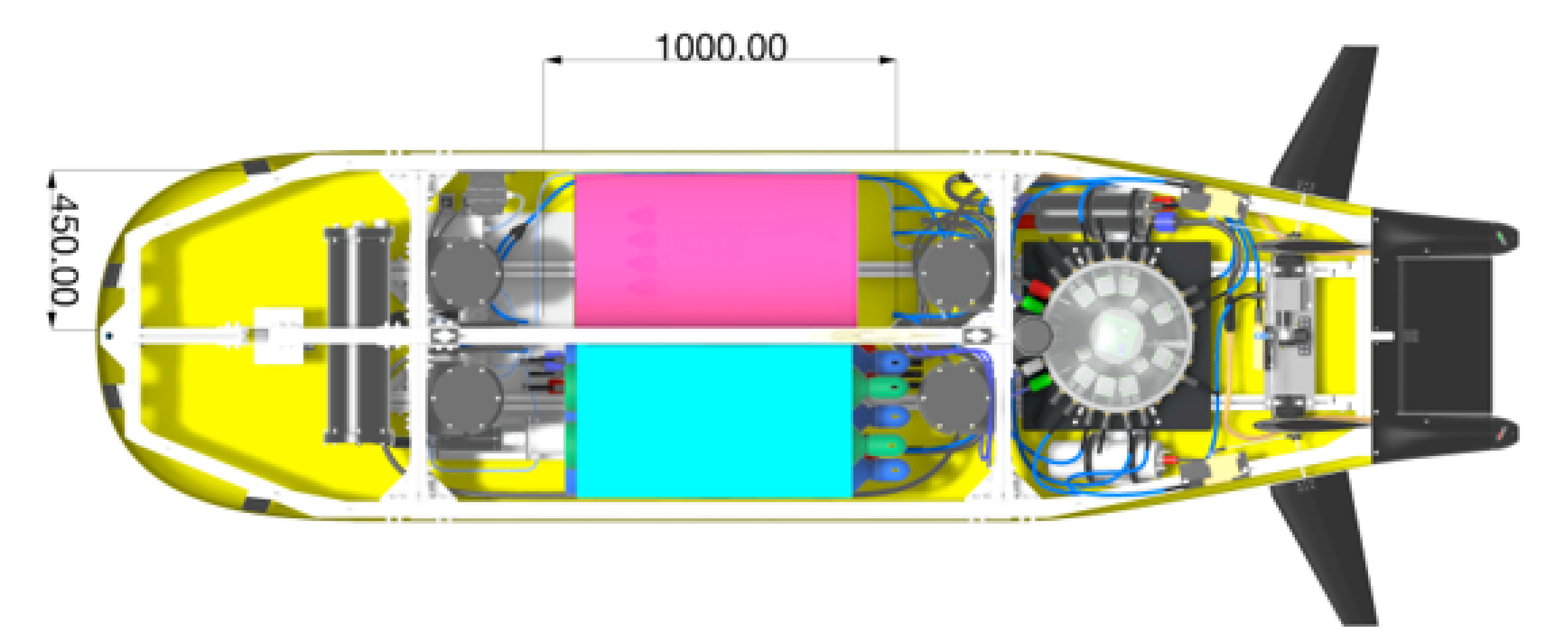
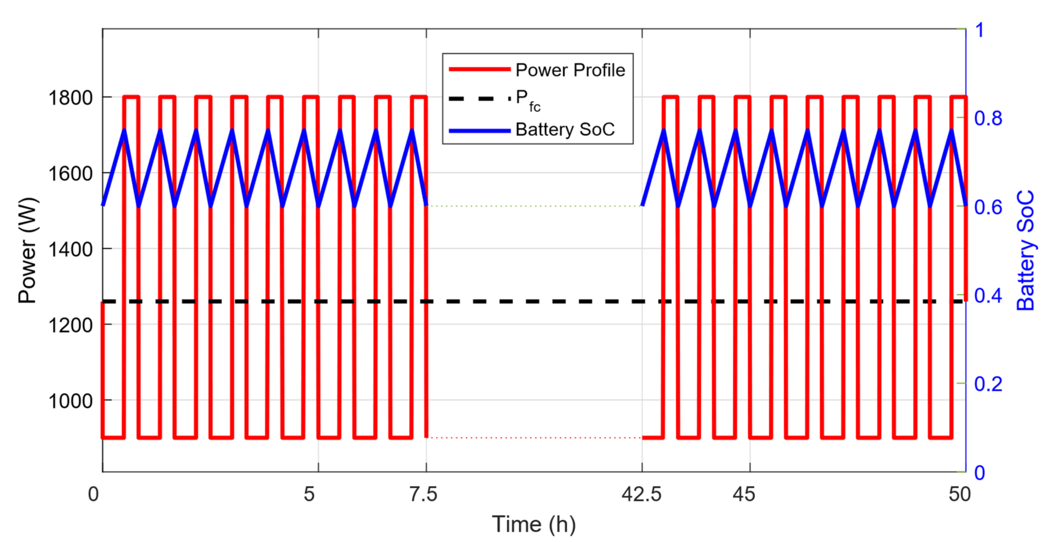
The MCDM method is used to compare and rank the alternative energy systems considering several criteria that have different dimensions and meanings [36,37]. Such a method is commonly used in order to plan and perform projects in the fields of environmental sciences and energy [38,39,40,41,42,43]. The decision matrix, presented in Table 2, summarizes all the information available about the alternatives and the criteria. This decision matrix is fundamental in all MCDM studies [44,45].
A1–Am represent the different alternatives, C1–Cn are the considered criteria, w1-wn correspond to the criteria weight and Xij is the performance of the ith alternative for the jth criteria. The max/min annotation sets if a maximum or a minimum performance for the criterion is targeted. For example, in most applications, if the total cost is a criterion, the target is to minimize it, whereas the criterion efficiency is likely to be maximized. The score of each alternative can be calculated using the Simple Additive Weighting (SAW) method [44], as the sum of the performance multiplied by the appropriate criteria weight, where the k first criteria are to be maximized and the rest of the criteria are to be minimized.
S c o r e A i = j = 1 k x i j × w j j = k n x i j × w j
There are several techniques to determine the criteria weights [46]. Subjective criteria weighting, based on experts’ knowledge, is commonly used. For example, the Analytical Hierarchy Process is often used to subjectively estimate the criteria weights [42]. On the other hand, objective criteria-weighting methods exist and are used in this study. They are based on the amount of information contained in each criterion and require several mathematical calculations of the decision matrix [46,47]. For comparison, two objective criteria-weighting methods are considered in this study. It is debatable whether the methods are completely objective, as the choice of criteria can have an impact on the ranking between different system combinations. By using only quantitative and technical criteria, it is nevertheless considered here that a fair assessment of the impact of the heat balance on the design of the energy system is feasible.
The two methods used in this study are the entropy method (EM) and the CRiteria Importance Through Intercriteria Correlation (CRITIC) method. For both methods, the decision matrix has to be normalized. Details about the matrix normalization and weighting calculations are presented in Appendix B. The EM depends on the measurement of uncertain information contained in the decision matrix, it compares each value to the sum of the values. In contrast, the CRITIC method estimates information contained in the criteria using the difference between the maximum and the minimum value to compare each value.

3.3. Case Study

The Swedish Maritime Robotics Centre (SMaRC) aims to develop fuel cell-powered AUVs capable of performing long-range missions in unknown water environments. The studied AUV is named LoLo (long-range, long-endurance), and has been under development as a demonstrator platform for the SMaRC project [48]. In Figure 2, the general shape of the vehicle is presented. The design of this AUV targets the use of new technologies in different sectors, e.g., environmental sensing, ocean production and safeguarding society. The hydrogen and oxygen storage units are not yet decided, and the possibilities have to be compared. Thus, the method described above is applied in order to calculate the total heat and the storage heat generated or needed for each combination of hydrogen and oxygen storage units, and thereby rank them.
A hybrid fuel cell/battery system capable of performing a 50 h mission is considered in this study. Based on a previous volume-optimization study, the most suitable system should be composed of a 1.26 kW PEMFC combined with a 1 kWh battery pack and, respectively, carry 3.2 kg and 25.2 kg of hydrogen and oxygen. The fuel cell stack weighs 7.93 kg and has a volume of 10.4 L. The battery has a weight of 4.61 kg and a volume of 2.97 L. The power profile considered here, shown in Figure 3, corresponds to a typical survey mission performed by the AUV, with cyclic peak-power demand periods combined with base-power demand phases. During peak-power demand, both the fuel cell and the battery deliver power to the AUV, whereas, during base-power phases, only the fuel cell powers the AUV, while simultaneously recharging the battery pack. The fuel cell efficiency, η F C , is supposed to be 60% and the battery efficiency, η b a t t , is 95%. The amount of energy carried by the hybrid system is 64 kWh. The working temperature of the fuel cell is 70 °C, and the surrounding sea water is assumed to be at 5 °C, meaning that the produced liquid water cools down to this temperature after leaving the fuel cell.
In order to compare the energy systems with different combinations of hydrogen and oxygen storage units, five criteria, which are crucial parameters for AUV design, are considered in this study. The first two criteria refer to the energy content of the power system in combination with different storage units. C1 is the specific energy of the system, and C2 its energy density. These two criteria have to be maximized; indeed, the goal is to have a system as compact and light, and carrying as much energy, as possible. Volume and weight are limiting factors in underwater applications, but just as important is the buoyancy of the AUV. The third criterion, C3, is the volumetric mass of the energy system, which is to be minimized. A low volumetric mass of the energy system may be beneficial, as the needed weight to reach neutral buoyancy can consist of more sensors or other equipment. The last two criteria aim at including the heat in the decision-making process, alongside the energy content and the buoyancy. The total heat calculated for the energy system, Q t o t , is directly linked to the overall cooling needed; this is the fourth criterion (C4). The storage heat, Q s t o r a g e , refers to the local heat generated or needed only for the tanks to release the gas and bring it to the fuel cell temperature. This storage heat determines the local need of heating or cooling and constitutes criterion C5. As the values and signs for the total heat and the storage heat can vary, it is not yet possible to determine if the value should be targeted to be maximized or minimized; this is decided using the results from the heat calculations. Still, the goal is to have values as close to 0 W as possible.

4. Results

4.1. Heat Calculations for the Energy Storage Systems

All the heats described in the method section are calculated for the three hydrogen storage units and the three oxygen storage units presented in this study. The heat of reactant release from the tank, and the heat needed to heat the gas up to the fuel cell temperature for the different storage units, as well as their volume and weight, are given in Table 3. The release of oxygen from the chemical oxygen storage, H2O2, corresponds to an exothermic reaction, and therefore has a negative Q t a n k , as do the two compressed-gas units. The heat generated by the chemical oxygen storage (H2O2) is three times higher, in absolute value, than the heat for any of the two other oxygen storage units considered. It is also interesting to note that the energy needed to heat the gas up to the fuel cell temperature is higher for the two liquid storage units, i.e., LOX and LH2, than for the other storage units. This is due to the low temperatures inside the tanks of LOX and LH2, 91 K and 21 K, respectively, meaning that energy needs to be applied to bring the gas to the fuel cell temperature. On the other hand, the heat needed to release the hydrogen and the oxygen from liquid form is at least 10 times lower than the heat needed for the other storage units.
Table 4 shows the results of the heat generated by the fuel cell stack, the heat from the battery pack and the heat due to the cooling of the produced water, all of which are independent of the types of reactant storage selected. The heat produced by the fuel cell stack, Q f c , is more than 10 times higher than the other heats calculated, and it is also the largest contributor to the total heat.

4.2. Multi-Criteria Decision-Making Analysis

Each alternative energy system corresponds to a combination of oxygen storage and hydrogen storage with the fuel cell stack and battery pack. The resulting decision matrix is presented in Table 5. Based on the heat results, it can be observed that the performance of total heat criterion, C4, is always negative, meaning that cooling solutions need to be found. The lower the total heat performance is, the more important the cooling solution will be, meaning that the total heat criterion (C4) is to be maximized. In addition, the storage heat, Q s t o r a g e   , can be positive or negative, but the goal is to have this heat as close to 0 W as possible. Therefore, in order to be able to compare the values, the absolute value of Q s t o r a g e   will be used, and the value of C5 is to be minimized.
Using the decision matrix, Table 5, and two objective criteria-weighting techniques described in the method section, the weights of the five criteria are estimated. The results are presented in Table 6. Differences can be observed between the weights of the criteria when using the entropy and the CRITIC methods. On the one hand, with the entropy method, the specific energy (C1) and the volumetric mass (C3) have a similar weight. The storage heat criterion (C5) has the highest weight while the total heat criterion (C4) has a limited influence. This low influence is understandable, as the entropy method uses the degree of uncertainties contained in the decision matrix: for the heat criterion (C4), the variation between highest and the lowest values is more than 3 × 10⁴ whereas for the other criteria, this difference is couple of hundred, or even less for C3. In other words, there are significantly more uncertainties for the heat criterion than for the other criteria. On the other hand, with the CRITIC method, the importance of each criterion is almost equivalent. For both methods, the combined weights of the two heat-related criteria, C4 and C5, corresponds to more than 40% of the total weight of the criteria, meaning that the heat does contribute in the decision process.
Using the SAW method, Equation (5), it is possible to calculate the score of each alternative and to rank them accordingly. Table 7 gives the ranking of the nine different alternatives based on the entropy and the CRITIC methods. The final ranking is not identical same for the two methods but clear trends appear. The three best-ranked alternatives are the combination of LH2 with LOX (A8), the combination of LH2 with Comp O2 (A7) and the combination of Comp H2 with LOX (A2). In addition, the two worst-ranked alternatives are the combinations of Comp H2 with Comp O2 or H2O2 (A1 and A2).
The surrounding water temperature could have an impact on the total heat balance of the energy system. In the calculations for this 50 h mission, this temperature is assumed to be 5 °C and the heat released when cooling the produced water is equal to 2.14 kWh, which is 10 times lower than the heat generated by the fuel cell. Such a surrounding water temperature corresponds to a mission in a cold-water environment, e.g., in the Baltic Sea. If a mission in a warmer region is considered, the surrounding water temperature may in some cases be as high as 30 °C, which should instead lead to a heat release equal to 1.32 kWh. The heat released from cooling of water from the fuel cell is very small and has almost no impact on the total heat. Therefore, the results of the MCDM analysis do not vary significantly with the temperature of the surrounding water, meaning that the ranking of different combinations of storage units remains the same. Practical issues, such as condensation, can however occur and be influenced by this temperature and have to be addressed [12].
In addition, if the assumed working temperature of the fuel cell is higher, e.g., 120 °C or more, the heat balance is modified. The heat generated by the fuel cell increases, as well as the heat needed to bring the reactants at the same temperature as the fuel cell, and the heat released when the produced water cools down. In addition, the produced water is in gaseous form. However, the heat generated by the fuel cell remains the major contributor, meaning that the MCDM results and the ranking is not likely to change.

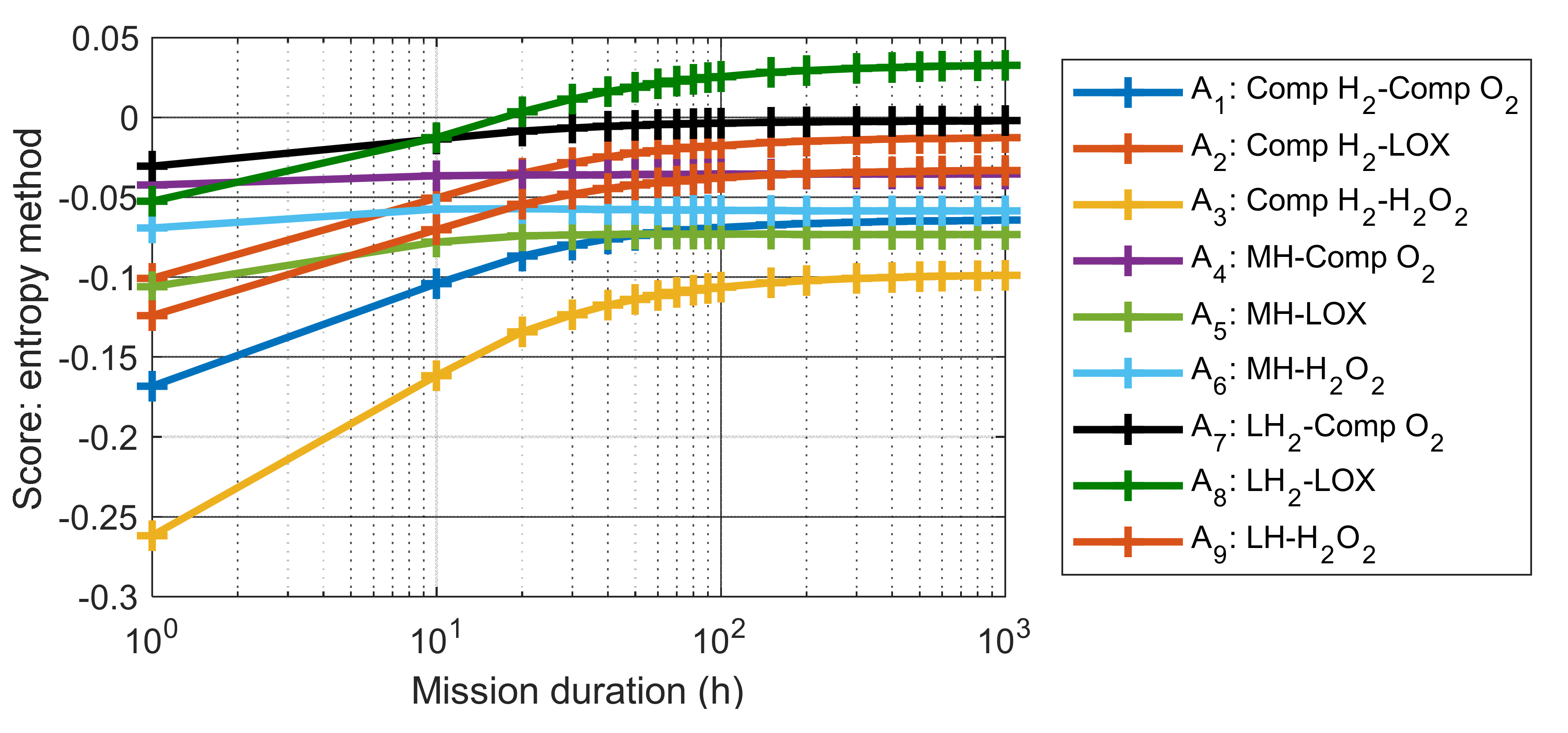
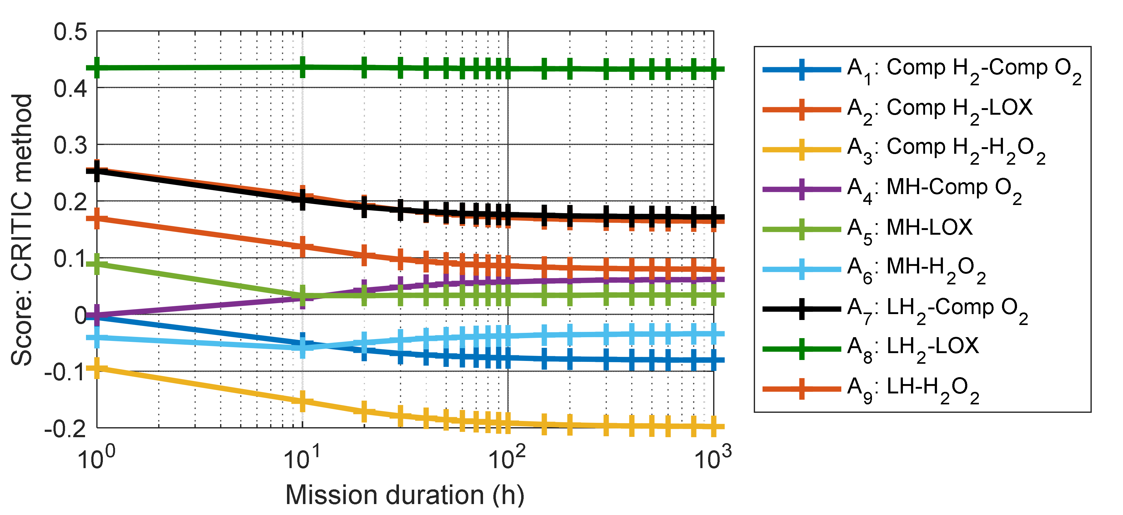
4.3. Influence of the Mission Duration

To study the influence of mission duration on the heat balance and MCDM results, the length of the mission was varied from 1 to 1000 h. The amount of hydrogen and oxygen needed varies with the mission duration, meaning that the energy density, the specific energy, the volumetric mass and the heat balance vary as well. For each mission considered, the same procedure as used for the 50 h mission is implemented, and the score of each alternative is calculated using both the entropy and the CRITIC weighting methods, see Figure 4 and Figure 5.
For both methods, and for all alternatives, the score changes when increasing the length of mission from 1 to 100 h, while a plateau is reached when duration of mission exceeds 100 h. This trend is due to the fact that the energy density and specific energy of the hybrid systems reach an asymptote when the mission duration increases, as observed in [4]. Furthermore, the best-ranked alternatives remain the same (A8, A7 and A2) for both methods when the mission becomes longer than 20 h, while the worst-ranked alternative is always the combination of Comp H2 and H2O2 (A3). It is notable that the evaluations of these scores can contain some uncertainties, however, the rank appears to be more important than the score itself. Since all these scores are calculated using the same methods, and since a plateau is reached, it means that the obtained ranking can be considered as valid.

5. Discussion

First of all, the fuel cell stack is the component contributing the most to the total heat, meaning that the thermal management strategy needs to be focused on the fuel cell stack. This result was expected as the fuel cell is the primary source of power within the vehicle. Since the fuel cell should be kept at a relatively constant temperature, the heat produced by the fuel cell needs to be evacuated and can help to maintain storage tanks at the desired temperature. For example, for the best-ranked alternative (LH2-LOX), the storage heat is positive, in other words, heat needs to be applied. Therefore, the heat produced by the fuel cell, instead of being evacuated, becomes a potential source of heat needed to maintain the release of hydrogen and oxygen. This last point shows the need for thermal management strategies for fuel cell-powered AUVs. This study also showed that the total heat due to a combination of liquid storage units is lower than most of the other combinations of storage units. The MCDM completes this analysis by weighting the different criteria, ranking the different alternatives of storage combinations and highlighting the most suitable alternative for the underwater application. All three best-ranked alternatives contain at least one liquid storage unit. This proves that it is relevant to consider storage units with a high energy content, such as liquid storage, as the major part of the heat to be handled comes from the fuel cell. As explained in [49], liquid hydrogen is seen as a promising alternative, especially for vehicles performing regular missions. AUVs performing daily coast-guarding or ocean-production missions can be considered for the implementation of liquid hydrogen. Results also show that the use of liquid oxygen should be considered for these applications.
The total heat calculated, Q t o t , is directly linked to the cooling power needed to ensure that the total heat balance within the power system of the AUV is neutral, which is one of the major challenges for AUVs [12]. This cooling power is equal to the ratio of the total heat and the duration of the mission. For the combination of Comp H2 with H2O2 (A3), this cooling power is equal to 2.14 kW, whereas for the combination of MH with LOX (A5), it is 970 W. The surrounding water is the only source of cooling for the system during the mission, and cooling is performed through simple conduction between the water and the energy system. The thermal conductivity of the energy system, its thickness and shape and the temperature of the surrounding water are the major parameters influencing the conduction. Therefore, the final size, shape and geometry of the vehicle become crucial and the question of whether or not the hydrogen and oxygen tanks should be isolated or in direct contact with the sea water has to be answered when designing the system. It is also important to note that other parts of the AUV produce heat, e.g., the main computer and the sensors, meaning that the cooling power also needs to be estimated globally for the AUV.
Two objective criteria-weighting methods are used in this study in order to perform the MCDM analysis. Such an approach is helpful when comparing the different solutions of storage combination for the underwater application. The results show that H2O2 storage is not the best option for AUVs. However, these weighting methods are based on the amount of information contained in each criterion; in other words, they are based on statistical considerations of the decision matrix. The weighting does not include any subjective approach, which can lead to a gap between the priorities of the experts and the results of the objective weighting methods. Thus, the authors suggest that objective criteria-weighting methods should be used as a first step in the design process of energy systems for AUV, in order to rank the different storage units and select the best combinations. In a second step, subjective criteria weighting based on experts’ knowledge should be considered to better correspond to the specificities of underwater vehicles.
This MCDM analysis focuses on technical and quantitative aspects. Some criteria, such as the cost of the different energy system alternatives, are fully quantitative and can be added to extend the analysis. Other criteria, such as safety, user friendliness, availability, practical complexity and reliability, are qualitative, and can therefore be more complicated to evaluate. Nevertheless, such qualitative criteria are essential to consider in order to design an efficient fuel cell-powered AUVs, and need to be investigated in the future. An example of subjective ranking of different storage units is provided in [12] for several quantitative performances, e.g., gravimetric density, and qualitative performances, e.g., the system simplicity. To reiterate, considering qualitative criteria adds a certain degree of subjectivity in the MCDM and should rather be carried out in a second step. Furthermore, the methodology used in this study, i.e., heat balance estimation and MCDM, can be applied to other types of fuel cell applications such as cars, trucks, buses and boats in order to determine the best hydrogen storage for each application. For these applications, there is no need to consider the oxygen storage, which simplifies the calculations.

6. Conclusions

In this study, a methodology to calculate the heat balance of a hybrid fuel cell/battery system and to assess its impact on the design of fuel cell-powered AUVs is undertaken. The heat properties of the fuel cell, the battery and the reactants storage units can be included in the design process of a hybrid fuel cell/battery system. Combined with a Multi-Criteria Decision-Making analysis considering calculated heats, the energy density, the specific energy and the volumetric mass of the energy system, it was possible to objectively compare and rank the different alternatives of storage combinations. The results showed that:
  • The fuel cell is the major contributor to the total heat for all the combinations of storage units.
  • It is relevant and worth-while to consider storage units with a high energy content, such as liquid storage, since the heat from the fuel cell has to be handled in all cases.
  • Heat management strategies focused on the fuel cell are necessary.
  • Chemical storage of oxygen in hydrogen peroxide form seems to be unsuitable for the underwater application.
  • The three best rank combinations of reactants storage units for the LoLo AUV all have at least one reactant stored in liquid form, showing the potential of using liquid storage units for fuel cell-powered AUVs.

Author Contributions

Conceptualization, A.C., G.L. and C.L.; methodology, A.C., G.L. and C.L.; software, A.C.; validation, A.C., G.L., I.S. and C.L.; formal analysis, A.C.; investigation, A.C.; resources, G.L., C.L. and I.S.; data curation, A.C.; writing—original draft preparation, A.C.; writing—review and editing, A.C., G.L., I.S. and C.L.; visualization, A.C.; supervision, G.L., I.S. and C.L.; project administration, G.L., I.S. and C.L.; funding acquisition, G.L., I.S. and C.L. All authors have read and agreed to the published version of the manuscript.

Funding

This work was supported by Swedish Foundation for Strategic Research (SSF) through the Swedish Maritime Robotic Centre (SMaRC, IRC 15-0046).

Institutional Review Board Statement

Not applicable.

Informed Consent Statement

Not applicable.

Conflicts of Interest

The authors declare no conflict of interest.

Appendix A. Heat Calculations

The heat from the release of the reactant, Q t a n k ,   i , is calculated as:
Q T a n k ,     i = Δ H i M i   m i  
where Δ H i (J/mol) is the enthalpy due to the release, m i (kg) the amount of gas needed for the mission and M i (kg/mol) the molar mass of the species. Mass of reactants are based on the fuel cell output power, P f c (W), duration of the mission, t (h), Low Heating Value of hydrogen, L H V H 2 (J/kg) and efficiency of the fuel cell system, η f c   according to:
m H 2 = P f c × t η f c   × L H V H 2
m O 2 = m H 2 × M O 2 2 × M H 2
In the case of compressed gas, there is no chemical reaction and/or change of phase and Equation (A1) cannot be used. Instead, Equation (A4) is used to calculate the enthalpy of the release of compressed gas, d H . It is based on the change of pressure inside the tank, d P (Pa), volume of the gas, V (m3), change of entropy, d S (J/K) and gas temperature, T (K). Since the system is reversible (the tank can be refilled) and isolated, the change of entropy is considered equal to 0. Q t a n k C o m p is calculated using Equation (A5), where the volume of the gas, V i , can be approximated using the Van der Waal’s state equation of non-ideal gases, Equation (A6).
d H = V d P + T d S  
Q T a n k C o m p = P T a n k 1 V i d P
P i + a n i 2 V i 2 × V i n i b = n i R T i
where a and b are the Van der Waal’s constants for non-ideal gases, n i is the number of moles and T i is the gas temperature.
The released gas needs to be heated up to the fuel cell temperature. The required energy, Q i , depends on the temperature of the gas when leaving the tank, T t a n k , i (K), temperature of the fuel cell, T f c (K), specific heat of the gas, C p i (J/mol, K), mass of gas, m i and its molar mass M i :
Q i = T f c T T a n k , i × C p i × m i M i
The temperature of the released compressed gas assumed is the coldest temperature possible, meaning that it is the same temperature as the surrounding water. This was carried out in order to estimate the maximum possible energy needed to heat the released gas up to the fuel cell temperature.
The heat generated by the fuel cell stack, Q f c , is estimated in Equation (A8) by assuming that liquid water is produced:
Q f c = Δ H f , H 2 O , l i q × m H 2 M H 2 + 0 t P f c t   d t
The heat generated by the battery pack is calculated using the battery power, P b a t t (W), its efficiency, η b a t t and the duration of the mission, t:
Q b a t t = 0 t a b s P b a t t t × 1 η b a t t   d t  
The produced liquid water in the fuel cell is assumed to be cooled down to the temperature of the surrounding environment (sea water temperature for example) generating energy, Q w a t e r , according to:
Q w a t e r = C p H 2 O l i q × T w a t e r   T f c   × m H 2     M H 2
where C p H 2 O , l i q , is the specific heat of liquid water and T w a t e r   T f c   the temperature difference between the surrounding water and the fuel cell.

Appendix B. Multi-Criteria Decision-Making (MCDM) and Objective Criteria Weighting

The entropy method (EM) depends on the measurement of uncertain information contained in the decision matrix. In order to obtain the criteria weights using this entropy method, the decision matrix is normalized as shown in Equation (A11). Based on this normalized matrix, the amount of information contained in each criterion (ej) is calculated using Equation (A11).
r i j = x i j i = 1 m x i j
e j = 1 ln n i = 1 m r i j × ln r i j
The degree of divergence (dj) of the amount of information contained in the jth criterion is determined as shown in Equation (A13), and the criterion weight is deduced, Equation (A14).
d j = 1 e j
w j = d j j = 1 n d j
Another way to obtain the criteria weights is the CRiteria Importance Through Intercriteria Correlation (CRITIC) method. The information contained in the criteria is calculated using analytical testing of the decision matrix. As for the entropy method, the decision matrix is normalized, as presented in Equation (A15), and the amount of information contained in each criterion (Cj) is calculated using Equation (A16).
r i j = x i j x j m i n x j m a x x j m i n
C j = σ j k = 1 n 1 r j k '
With σ j being the standard deviation of the jth criterion and r j k ' corresponds to the correlation coefficient between the jth and the kth criteria. The weights can be calculated using the Cj values:
w j = C j j = 1 n C j

References

  1. Cai, Q.; Brett, D.J.L.; Browning, D.; Brandon, N.P. A sizing-design methodology for hybrid fuel cell power systems and its application to an unmanned underwater vehicle. J. Power Sources 2010, 195, 6559–6569. [Google Scholar] [CrossRef]
  2. Albarghot, M.M.; Iqbal, M.T.; Pope, K.; Rolland, L. Sizing and Dynamic Modeling of a Power System for the MUN Explorer Autonomous Underwater Vehicle Using a Fuel Cell and Batteries. J. Energy 2019, 2019, 4531497. [Google Scholar] [CrossRef] [Green Version]
  3. Gilljam, M.; Weydahl, H.; Lian, T.; Johannessen, T.C.; Holm, S.I.; Hasvold, J.O. 24 hour test of a fuel cell system for an autonomous underwater vehicle. ECS Trans. 2016, 71, 145. [Google Scholar] [CrossRef]
  4. Chiche, A.; Lindbergh, G.; Stenius, I.; Lagergren, C. A Strategy for Sizing and Optimizing the Energy System on Long-Range AUVs. IEEE J. Ocean. Eng. 2021, 1–12. [Google Scholar] [CrossRef]
  5. Mendez, A.; Leo, T.J.; Herreros, M.A. Current state of technology of fuel cell power systems for autonomous underwater vehicles. Energies 2014, 7, 4676–4693. [Google Scholar] [CrossRef] [Green Version]
  6. Psoma, A.; Sattler, G. Fuel cell systems for submarines: From the first idea to serial production. J. Power Sources 2002, 106, 381–383. [Google Scholar] [CrossRef]
  7. Sawa, T.; Aoki, T.; Yamamoto, I.; Tsukioka, S.; Yoshida, H.; Hyakudome, T.; Ishibashi, S.; Inada, T.; Kabeno, T.; Sasamoto, R.; et al. Performance of the fuel cell underwater vehicle URASHIMA. Acoust. Sci. Technol. 2005, 26, 249–256. [Google Scholar] [CrossRef] [Green Version]
  8. Hornfeld, W. DeepC the German AUV Development Project; Technical report for STN ATLAS Elektronik GmbH; STN ATLAS Elektronik GmbH: Bremen, Germany, 2002. [Google Scholar]
  9. Cellula Robotics Solus Long Range AUV. Available online: https://www.cellula.com/solus-lr (accessed on 12 February 2020).
  10. Saadi, A.; Becherif, M.; Hissel, D.; Ramadan, H.S. Dynamic modeling and experimental analysis of PEMFCs: A comparative study. Int. J. Hydrogen Energy 2017, 42, 1544–1557. [Google Scholar] [CrossRef]
  11. D’Amore-Domenech, R.; Raso, M.A.; Villalba-Herreros, A.; Santiago, Ó.; Navarro, E.; Leo, T.J. Autonomous underwater vehicles powered by fuel cells: Design guidelines. Ocean Eng. 2018, 153, 387–398. [Google Scholar] [CrossRef]
  12. Weydahl, H.; Gilljam, M.; Lian, T.; Johannessen, T.C.; Holm, S.I.; Hasvold, J.Ø. Fuel cell systems for long-endurance autonomous underwater vehicles—Challenges and benefits. Int. J. Hydrogen Energy 2020, 45, 5543–5553. [Google Scholar] [CrossRef]
  13. Schmitt, M.; Nasri, M. Thermal management concept for next generation vehicles. In Proceedings of the 2015 Tenth International Conference on Ecological Vehicles and Renewable Energies (EVER), Monte Carlo, Monaco, 31 March–2 April 2015. [Google Scholar] [CrossRef]
  14. Nasri, M.; Burger, I.; Michael, S.; Friedrich, H.E. Waste heat recovery for fuel cell electric vehicle with thermochemical energy storage. In Proceedings of the 2016 Eleventh International Conference on Ecological Vehicles and Renewable Energies (EVER), Monte Carlo, Monaco, 6–8 April 2016; pp. 1–6. [Google Scholar] [CrossRef] [Green Version]
  15. Pfeifer, P.; Wall, C.; Jensen, O.; Hahn, H.; Fichtner, M. Thermal coupling of a high temperature PEM fuel cell with a complex hydride tank. Int. J. Hydrogen Energy 2009, 34, 3457–3466. [Google Scholar] [CrossRef]
  16. Nasri, M.; Dickinson, D. Thermal management of fuel cell-driven vehicles using HT-PEM and hydrogen storage. In Proceedings of the 2014 Ninth International Conference on Ecological Vehicles and Renewable Energies (EVER), Monte Carlo, Monaco, 25–27 March 2014. [Google Scholar] [CrossRef] [Green Version]
  17. Hyakudome, T.; Nakatani, T.; Yoshida, H.; Tani, T.; Ito, H.; Sugihara, K. Development of fuel cell system for long cruising lange Autonomous Underwater Vehicle. In Proceedings of the 2016 IEEE/OES Autonomous Underwater Vehicles (AUV), Tokyo, Japan, 6–9 November 2016; pp. 165–170. [Google Scholar]
  18. Swider-Lyons, K.E.; Carlin, R.T.; Rosenfeld, R.L.; Nowak, R.J. Technical issues and opportunities for fuel cell development for autonomous underwater vehicles. In Proceedings of the 2002 Workshop on Autonomous Underwater Vehicles, San Antonio, TX, USA, 21–21 June 2002; 2002; pp. 61–64. [Google Scholar]
  19. Niaz, S.; Manzoor, T.; Pandith, A.H. Hydrogen storage: Materials, methods and perspectives. Renew. Sustain. Energy Rev. 2015, 50, 457–469. [Google Scholar] [CrossRef]
  20. Durbin, D.J.; Malardier-Jugroot, C. Review of hydrogen storage techniques for on board vehicle applications. Int. J. Hydrogen Energy 2013, 38, 14595–14617. [Google Scholar] [CrossRef]
  21. Stetson, N.T.; McWhorter, S.; Ahn, C.C. Introduction to Hydrogen Storage; Elsevier Ltd.: Amsterdam, The Netherlands, 2016; Volume 2006, ISBN 9781782423621. [Google Scholar]
  22. Rusman, N.A.A.; Dahari, M. A review on the current progress of metal hydrides material for solid-state hydrogen storage applications. Int. J. Hydrogen Energy 2016, 41, 12108–12126. [Google Scholar] [CrossRef]
  23. Baumert, R.; Epp, D. Engineering in Harmony with the Ocean. In Proceedings of OCEANS’93; IEEE: Victoria, BC, Canada, 1993; p. II—166. ISBN 0780313852. [Google Scholar]
  24. Wang, H.; Prasad, A.K.; Advani, S.G. Hydrogen storage systems based on hydride materials with enhanced thermal conductivity. Int. J. Hydrogen Energy 2012, 37, 290–298. [Google Scholar] [CrossRef]
  25. Abdin, Z.; Webb, C.J.; Gray, E.M.A. One-dimensional metal-hydride tank model and simulation in Matlab–Simulink. Int. J. Hydrogen Energy 2018, 43, 5048–5067. [Google Scholar] [CrossRef]
  26. Hyakudome, T.; Yoshida, H.; Tsukioka, S.; Sawa, T.; Ishibashi, S.; Aoki, T.; Iwamoto, T.; Kawaharazaki, Y.; Muto, A.; Oda, T.; et al. High Efficiency Hydrogen and Oxygen Storage System Development for Underwater Platforms Powered by Fuel Cell. ECS 2010, 465–474. [Google Scholar] [CrossRef]
  27. Valenti, G. Hydrogen Liquefaction and Liquid Hydrogen Storage; Elsevier Ltd.: Amsterdam, The Netherlands, 2016; Volume 23, ISBN 9781782423621. [Google Scholar]
  28. Davies, K.L.; Moore, R.M. UUV FCEPS Technology Assessment and Design Process. System 2006, 34. [Google Scholar] [CrossRef]
  29. Sun, X.W.; Guo, Z.Y.; Huang, W. Passive zero-boil-off storage of liquid hydrogen for long-time space missions. Int. J. Hydrogen Energy 2015, 40, 9347–9351. [Google Scholar] [CrossRef]
  30. Ahluwalia, R.K.; Hua, T.Q.; Peng, J.K. On-board and Off-board performance of hydrogen storage options for light-duty vehicles. Int. J. Hydrogen Energy 2012, 37, 2891–2910. [Google Scholar] [CrossRef]
  31. Plachta, D.W.; Christie, R.J.; Jurns, J.M.; Kittel, P. Passive ZBO storage of liquid hydrogen and liquid oxygen applied to space science mission concepts. Cryogenics 2006, 46, 89–97. [Google Scholar] [CrossRef]
  32. Moore, J.W.; Vitz, E.; Shorb, J. ChemPRIME: An Online Wiki Textbook with Exemplars; Amer Chemical Soc 1155 16TH ST, NW: Washington, DC, USA, 2011; Volume 242. [Google Scholar]
  33. An, L.; Zhao, T.; Yan, X.; Zhou, X.; Tan, P. The dual role of hydrogen peroxide in fuel cells. Sci. Bull. 2015, 60, 55–64. [Google Scholar] [CrossRef] [Green Version]
  34. Fukuzumi, S.; Yamada, Y. Hydrogen Peroxide Used as a Solar Fuel in One-Compartment Fuel Cells. ChemElectroChem. 2016, 3, 1978–1989. [Google Scholar] [CrossRef] [Green Version]
  35. Solvay, S.A. Hydrogen Peroxide Handling & Storage. Available online: http://larichile.cl/wp-content/uploads/2017/05/Hydrogen-peroxide-handling-storage.pdf (accessed on 27 November 2020).
  36. Mateo, J.R.S.C. Multi-Criteria Analysis in the Renewable Energy Industry. In Green Energy and Technology; Springer: London, UK, 2012; Volume 83. [Google Scholar]
  37. Ishizaka, A.; Nemery, P. Multi-Criteria Decision Analysis: Methods and Software; John Wiley & Sons: Chichester, UK, 2013; ISBN 9781119974079. [Google Scholar]
  38. Kumar, A.; Sah, B.; Singh, A.R.; Deng, Y.; He, X.; Kumar, P.; Bansal, R.C. A review of multi criteria decision making (MCDM) towards sustainable renewable energy development. Renew. Sustain. Energy Rev. 2017, 69, 596–609. [Google Scholar] [CrossRef]
  39. Pohekar, S.D.; Ramachandran, M. Application of multi-criteria decision making to sustainable energy planning—A review. Renew. Sustain. Energy Rev. 2004, 8, 365–381. [Google Scholar] [CrossRef]
  40. Greening, L.A.; Bernow, S. Design of coordinated energy and environmental policies: Use of multi-criteria decision-making. Energy Policy 2004, 32, 721–735. [Google Scholar] [CrossRef]
  41. Ligus, M. Evaluation of economic, social and environmental effects of low-emission energy technologies in Poland -multi-criteria analysis. Energy Procedia 2017, 136, 163–168. [Google Scholar] [CrossRef]
  42. Abudeif, A.M.; Abdel Moneim, A.A.; Farrag, A.F. Multicriteria decision analysis based on analytic hierarchy process in GIS environment for siting nuclear power plant in Egypt. Ann. Nucl. Energy 2015, 75, 682–692. [Google Scholar] [CrossRef]
  43. Van de Kaa, G.; Fens, T.; Rezaei, J. Residential grid storage technology battles: A multi-criteria analysis using BWM. Technol. Anal. Strateg. Manag. 2019, 31, 40–52. [Google Scholar] [CrossRef]
  44. Vujicic, M.; Papic, M.; Blagojevic, M. Comparative analysis of objective techniques for criteria weighing in two MCDM methods on example of an air conditioner selection. Tehnika 2017, 72, 422–429. [Google Scholar] [CrossRef] [Green Version]
  45. D’Amore-Domenech, R.; Santiago, Ó.; Leo, T.J. Multicriteria analysis of seawater electrolysis technologies for green hydrogen production at sea. Renew. Sustain. Energy Rev. 2020, 133, 110166. [Google Scholar] [CrossRef]
  46. Odu, G.O. Weighting methods for multi-criteria decision making technique. J. Appl. Sci. Environ. Manag. 2019, 23, 1449. [Google Scholar] [CrossRef] [Green Version]
  47. Adalı, E.A.; Işık, A.T. Critic and Maut Methods for the Contract Manufacturer Selection Problem. Eur. J. Multidiscip. Stud. 2017, 5, 93. [Google Scholar] [CrossRef] [Green Version]
  48. Deutsch, C.; Moratelli, L.; Thune, S.; Kuttenkeuler, J.; Soderling, F. Design of an AUV Research Platform for Demonstration of Novel Technologies. In Proceedings of the 2018 IEEE/OES Autonomous Underwater Vehicle Workshop (AUV), Porto, Portugal, 6–9 November 2018. [Google Scholar] [CrossRef]
  49. Arnold, G.; Wolf, J. Liquid Hydrogen for Automotive Application Next Generation Fuel for FC and ICE Vehicles. TEION KOGAKU (J. Cryog. Supercond. Soc. Jpn.) 2005, 40, 221–230. [Google Scholar] [CrossRef] [Green Version]
Figure 1. General scheme of the closed hybrid fuel cell/battery energy system for AUVs with the different heats considered.
Energies 14 04920 g001
Figure 2. Top view of the AUV-concept LoLo with the hybrid fuel cell/battery system integrated (blue and pink blocks) including dimensional constraints (dimensions in mm).
Energies 14 04920 g002
Figure 3. Power profile and evolution of the battery state-of-charge for a 50 h mission.
Energies 14 04920 g003
Figure 4. The score of each alternative as a function of the mission duration, calculated with the entropy method.
Energies 14 04920 g004
Figure 5. The score of each alternative as a function of the mission duration, calculated with the CRITIC method.
Energies 14 04920 g005
Table 1. Properties of the different hydrogen- and oxygen storage solutions (Adapted from [4,5]).
Storage TypeEnergy Density (Wh/L)Specific Energy (Wh/kg)Gravimetric Density
(kggas/kgstorage)
Volumetric Density
(kggas/m3storage)
Release ProcessThermal Property
Compressed hydrogen650–7001100–17100.06070.80Pressure differenceExothermic
Metal hydrides770–1670280–5200.020115.0Hydrogen desorptionEndothermic
Liquid hydrogen122016200.14235.00VaporizationEndothermic
Compressed oxygen600–1090770–16800.213166.7VaporizationExothermic
Liquid oxygen2780–29802900–33000.786661.0Pressure differenceEndothermic
Oxygen in chemical form 1340–20901170–13000.303(H2O2)348.8(H2O2)Chemical reactionExothermic
Table 2. Layout of a typical decision matrix for MCDM analysis.
AlternativesCriteria
C1C2-Cn
w1w2-wn
(Max/Min)(Max/Min)(Max/Min)(Max/Min)Score or Rank
A1X11X12-X1nR1
A2X21X22-X2nR2
------
AmXm1Xm2-XnmRn
Table 3. Results of the heat calculations for the reactants storage solutions and the heating of the gases to fuel cell temperature.
Comp H2 *MHLH2Comp O2 *LOXH2O2
Δ H i
(J/mol)
a = 0.2453 bar·L2/mol2
b = 0.02651 L/mol
30,000904a = 1.382 bar·L2/mol2
b = 0.03186 L/mol
6820−108,000
V (L)90.027.444.515138.272.3
Weight (kg)52.515822.211832.183.2
T O 2 / H 2 t a n k
(K)
2783032127891313
Q t a n k
(Wh)
−1.91 × 10⁴ 1.31 × 104396−8.41 × 1031.49 × 103−2.36 × 10⁴
Q g a s
(Wh)
8335054.06 × 1034191.62 × 103193
* a and b refer to the constants for the Van der Waals’ state equation.
Table 4. Heat generated by the fuel cell stack, the battery pack and due to the cooling of the produced water.
Q F C   ( Wh ) Q b a t t   ( Wh ) Q w a t e r   ( Wh )
−6.18 × 10⁴−1.35 × 10³−2.14 × 10³
Table 5. Decision matrix to select the best energy-storage system for an AUV performing the described mission.
AlternativeC1: Specific Energy (Wh/kg)C2: Energy Density (Wh/L)C3: Volumetric Mass (kg/L) C 4 :   Total   Heat   Q t o t     ( Wh ) C 5 :   Storage   Heat   Q s t o r a g e     ( Wh )
MaxMaxMinMaxMin
A1: Comp H2-Comp O23432470.72−9.15 × 10⁴−2.63 × 10⁴
A2: Comp H2-LOX6484450.68−8.04 × 10⁴−1.51 × 10⁴
A3: Comp H2-H2O24243580.84−10.7 × 10⁴−4.19 × 10⁴
A4: MH-Comp O22183281.50−5.96 × 1045.65 × 103
A5: MH-LOX3117982.56−4.85 × 1041.67 × 104
A6: MH-H2O22485572.24−7.51 × 10⁴−9.80 × 10³
A7: LH2-Comp O24113010.73−6.88 × 10⁴−3.54 × 10³
A8: LH2-LOX9436560.70−5.77 × 1047.57 × 103
A9: LH2-H2O25344840.91−8.42 × 10⁴−1.90 × 10⁴
Table 6. Criteria weights based on the entropy and on the CRITIC methods.
MethodSpecific Energy (C1)Energy Density (C2)Volumetric Mass (C3)Total Heat (C4)Storage Heat (C5)
Entropy method0.180.120.250.050.40
CRITIC0.210.140.220.180.25
Table 7. Ranking of the different alternatives of energy-storage systems to perform the AUV mission, using the entropy and the CRITIC methods (1 being the best-ranked alternative and 9 the worst-ranked alternative).
MethodComp H2-Comp O2 (A1)Comp H2-LOX (A2)Comp H2-H2O2 (A3)MH-
Comp O2 (A4)
MH-LOX (A5)MH-
H2O2 (A6)
LH2-Comp O2 (A7)LH2-LOX (A8)LH2-H2O2 (A9)
EM839476215
CRITIC839567214
Publisher’s Note: MDPI stays neutral with regard to jurisdictional claims in published maps and institutional affiliations.

