Review

Short Survey of Architectures of Photovoltaic Arrays for Solar Power Generation Systems

by
Alexander Abramovitz
1,* and
Doron Shmilovitz
2
1
Department of Electrical Engineering, Faculty of Engineering, Holon Institute of Technology, 52 Golomb St., Holon 5810201, Israel
2
Department of Physical Electronics, School of Electrical Engineering, Faculty of Engineering, Tel-Aviv University, P.O. Box 39040, Tel Aviv-Yafo 69978, Israel
*
Author to whom correspondence should be addressed.
Energies 2021, 14(16), 4917; https://doi.org/10.3390/en14164917
Submission received: 18 June 2021 / Revised: 4 August 2021 / Accepted: 6 August 2021 / Published: 11 August 2021

Abstract

:
Since the industrial revolution, the world’s economy has mainly relied on the consumption of fossil fuels. The burning of coal releases vast amounts of toxic COx greenhouse gasses into the atmosphere that bear an undesirable environmental impact. The ongoing offshore oil exploration activities; the infrastructure for oil extraction, production, and transportation; and the inevitable oil spills cause severe damage to the environment and huge loss of sea life, flora, and fauna. Recent awareness of the environmental issues and the worldwide climate change spurred public interest in clean and environmentally friendly “green” energy generation. Solar energy is an abundant and inexhaustible resource that can meet much of the worlds’ energy needs and, thus, has been in the focus of scientific attention for many years. Yet, converting solar energy into usable electric power is a formidable engineering and economical challenge. The recent environmental awareness triggered governments and private companies around the world to encourage further research and capital investment into the development and deployment of efficient and cost-effective solar technologies. This review reports on advances in the technological approaches that can be employed to convert sunlight to electricity. This article presents a short survey of the state-of-the-art architectures of photovoltaic arrays and a review of the concepts and strategies of their associated electronic power processors for solar energy generation. The paper aims to be of assistance to engineers and scientists who are already engaged or just joining this fascinating field, to promote the knowledge of photovoltaic energy and facilitate the proliferation of the solar power generation systems.

1. Introduction

The 1921 Nobel Prize in Physics was awarded to Albert Einstein “for his services to Theoretical Physics, and especially for his discovery of the law of the photoelectric effect” [1]. This exciting discovery further inspired humanity’s futuristic dream to harness the sun for free energy. While indeed free and, in some parts of the world, abundant, solar energy is still challenging to capture, store and distribute to users on an economical basis. The primary disadvantages of solar energy generation systems are their intermittent nature, the limited conversion efficiency of commercially available photovoltaic (PV) cells, and the high capital investment. The cost of the solar generation system can be reduced by improving the photovoltaic conversion efficiency so that smaller and cheaper systems can be used. Less hardware, installation, labor, and real estate costs can improve the Total Life Cycle Cost of solar energy [2] and, consequently, increase the penetration of solar energy generation systems into the global energy market.
The small physical dimensions of a PV cell allow limited amount of solar irradiation to be captured, providing only a minute amount of electrical power. To generate a practically usable amount of energy, a large number of PV cells have to be stacked together to form an array, also referred to as a PV panel or single PV module. Commercially available PV modules are field-installable units, typically 1–3 m2 in size, which can generate about 150–300 W each. Grid-connected PV generating systems are designed to supply much higher power and require a considerable amount of PV modules to be assembled into a larger PV array [3]. Thus, the PV array is, in fact, an array of arrays composed of a huge number of basic PV cells and has complex wiring. The optimal utilization of such a large ensemble of PV cells is a rather intricate task.
The primary challenge is posed by the inherent non-linearity of the PV cell, which has a bell shape power-voltage curve with a unique maximum power point (MPP). The MPP is located at the knee of the voltage-current characteristics, where the abrupt slope change manifests the transition from current source behavior towards the voltage source region. Yet, in case of shading or malfunction, the P–V curve may comprise several distinct MPPs. Therefore, to extract the maximum available DC power out of the PV array, an electronic dynamic Maximum Power Point Tracker (MPPT) [4] and a proper power converter/inverter set are required to generate AC at utility compatible voltage level and connect to the grid.
In the field, under the ever-changing irradiation and temperature conditions, PV arrays frequently exhibit a loss of power. Hardware faults such as the partial or full opening of a string can occur due to environmental stresses or as a result of hot spot damage. Another common problem in operating large PV arrays is mismatched electrical characteristics due to the manufacturer’s tolerances, temperature differences, and shading. Shading can occur due to soiling, fallen leaves, bird droppings, and shadows cast from nearby objects. Shading is a continuous phenomenon and can vary between 0% and 100%. Partial shading implies that some areas of an array are shaded, while others are not. Under different insolation and, hence, also different temperature conditions the V–I curves of the PV cells are shifted relative to each other [5]. In a shaded hardwired array, not only that the PV cells operate at operating points apart from their unique MPP but also tend to interfere with each other. This causes the energy output of the entire PV array to drop significantly of its available capacity.
The wiring of the PV array, the power processing architecture and the MPPT algorithm have a significant effect on how the mismatch and shading affect the power yield of the PV system [6]. Over the years, researchers have extensively experimented with various PV architectures to maximize the energy yield of PV sources and make the system fault-tolerant, forbearing mismatch, and shading problems, while keeping the solution economically viable. To date, a formidable body of theoretical knowledge supported by extensive practical experience has been accumulated [5].
This paper surveys the hardware architectures of PV systems and reviews the concepts and strategies of their associated electronic power processors to reveal the state of the art and provide a reference for scientists, designers, and engineers. The rest of the paper is organized as follows: in Section 2, the fixed PV array configurations and their associated shading problems are described; Section 3 reports the variable array structures; Section 4 surveys the electronic power processors, converters, and equalizers that can be used to increase the yield and efficiency of the PV energy conversion; Section 5 updates on the emerging concentrated photovoltaic systems; some facts on public acceptance of the PV systems are stated in Section 6; lastly, the Summary section concludes the paper.

2. Static PV Arrays

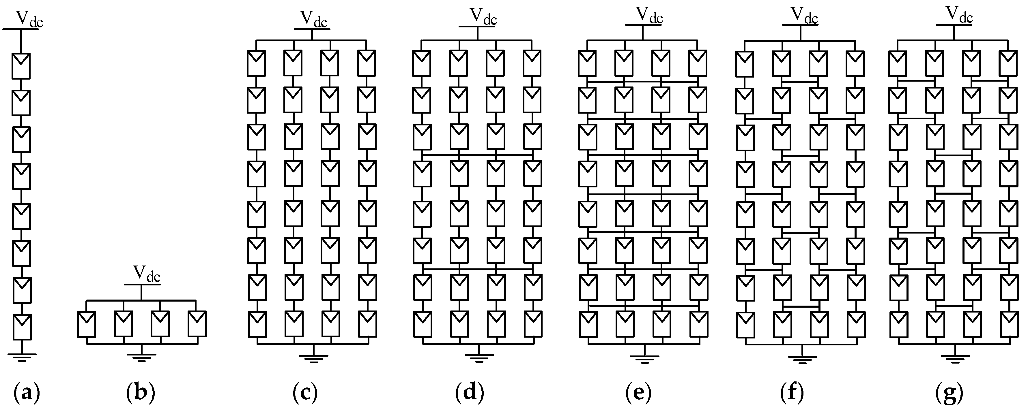
2.1. Common Interconnection Patterns of PV Cells and Modules

To help limit the mismatch and shading effects, the wiring pattern of the PV array has to be considered to identify architecture with sufficient redundancy. Several possible PV arrays’ interconnection schemes were reported early in the literature [7,8]. These include the Series (S); the Parallel (P); the Series–Parallel (SP); the Series–Parallel–Series (SPS); the Total-Cross-Tied (TCT); the Bridge-Linked (BL); and the Honey-Comb (HC) arrays, illustrated in Figure 1a–g, respectively. A simple S array can attain high output voltage at low output current while the P array can provide the highest output current, but only at the low output voltage. The S array is also referred to as the string, whereas the P array is the tier. Both S and P arrays have the simplest wiring. The SP array can output both a high voltage and high current, yet it has simple wiring. The SPS array is formed by connecting several short SP sub-arrays in series.
The TCT array is a string of PV tiers and has a simple setup but also the longest wiring. The BL array has its modules interconnected in bridge rectifier fashion and has a rather complex interconnection. The “honeycomb” pattern of the HC array can be revealed when Figure 1g is “stretched” horizontally. The HC array has the most complex wiring, which is less of a problem for PV modules manufacturers, but can be demanding for constructing large field installations. In the ideal case, SP, SPS, TCT, BL, and HC arrays can all provide the same high voltage and current; however, the merits of these arrays are in their ability to cope with shading conditions.

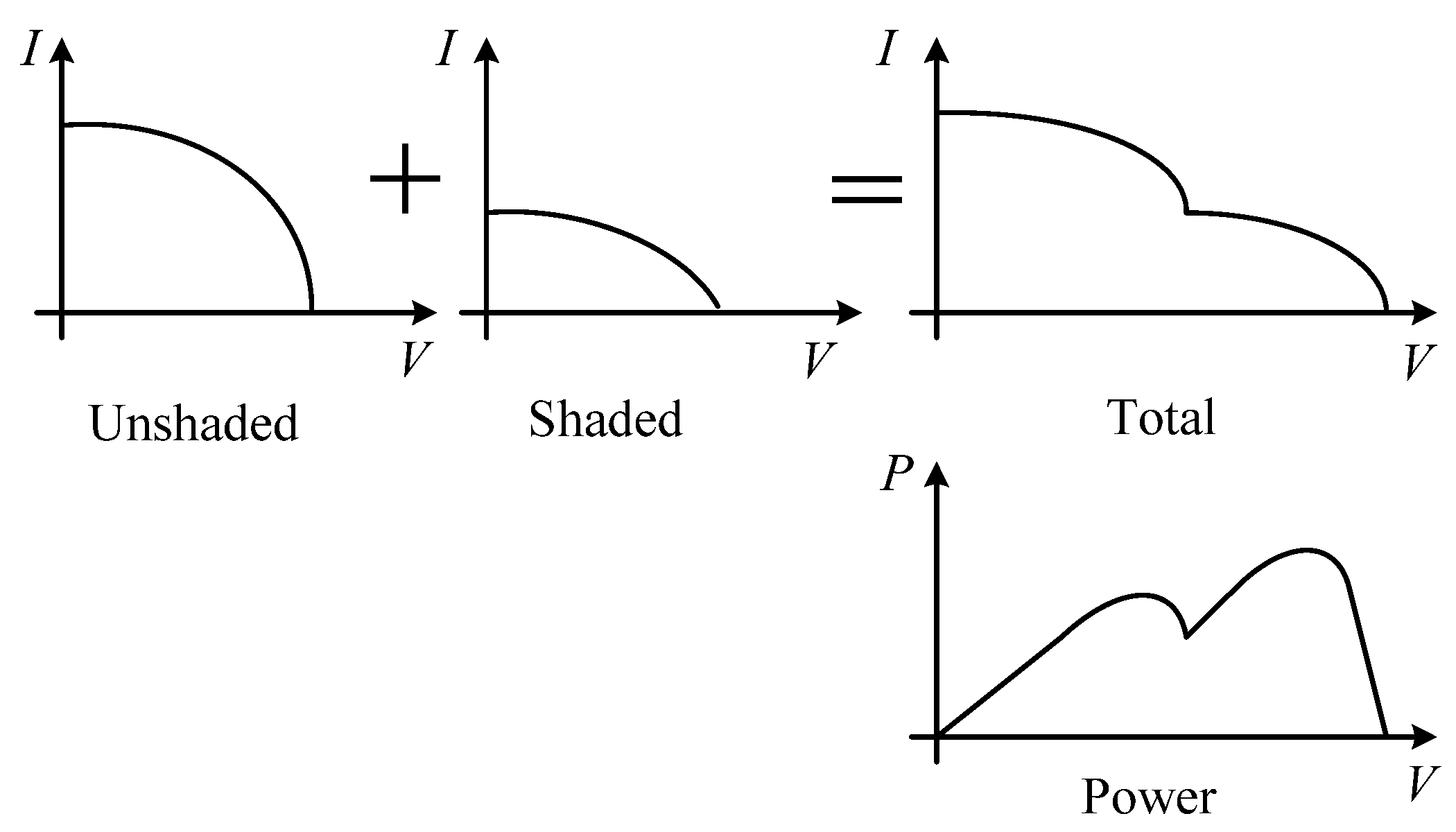
2.2. Tolerance of Commonly Used Arrays to Shading
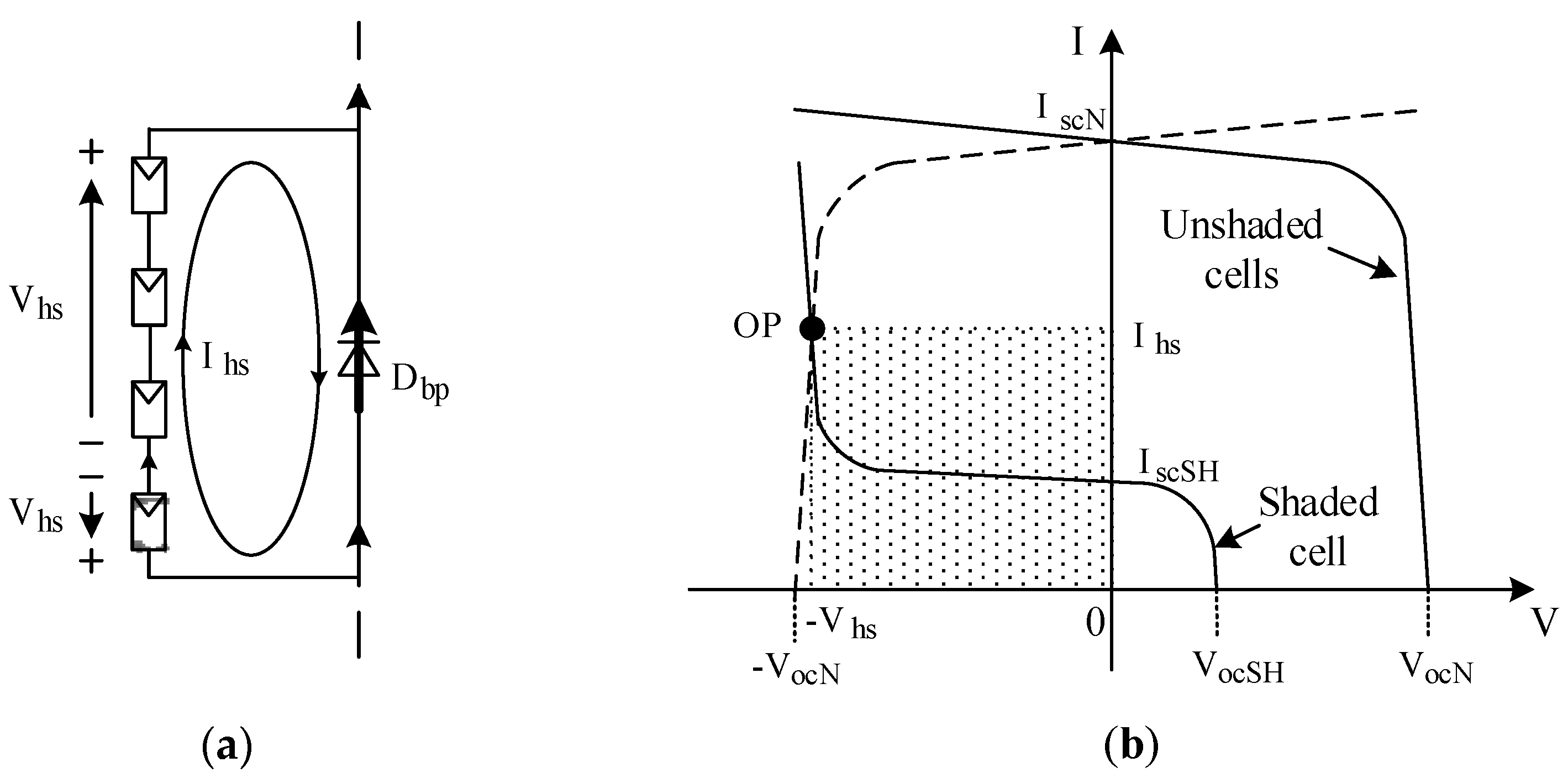
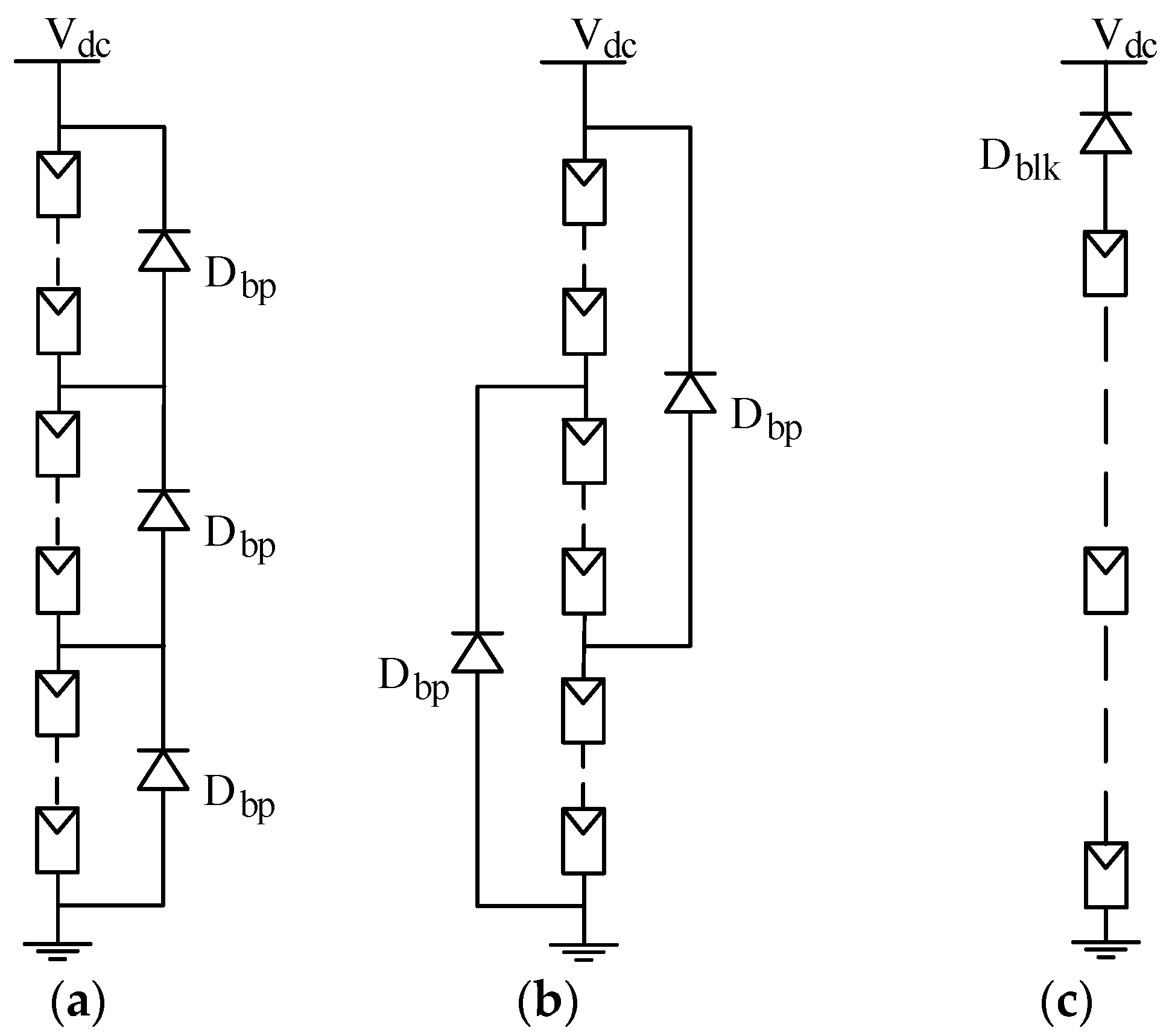
The PV module interconnection pattern determines the array’s tolerance to shading [9,10,11,12]. Since PV voltage is logarithmically proportional to irradiation, it exhibits less sensitivity to fluctuations. The paralleled cells/modules operate at the same voltage and closer to the maximum power point altogether regardless of their respective irradiance. As the failed module does not affect the neighboring modules, the drop in the energy yield of the P array is only due to the failed module getting offline. Thus, the P array has excellent fault tolerance due to its high level of redundancy, whereas the current of the series-connected substrings is limited by that of the weakest cell. A malfunction of one of the modules in the string limits the current and can severely impair or even cut off the energy production of the entire string. The resultant energy generation loss of the S array is much greater than the percentage of the array’s shaded area. Hence, the S array has zero interconnection redundancy and the lowest tolerance.
The shape of the array’s V–I curve changes when shadows are cast. While P arrays tend to maintain an easier-to-track single MPP, the composite V–I curve of the S array may include several local maxima points [10]. Both occur due to mismatch losses, and losses due to failure in tracking the global MPP the long S and SP arrays are more prone to loss of power than the short SP or short SPS arrays. Short strings controlled individually seem to deliver the most reliable power production [13]. Therefore, increasing tolerance to shading conditions and the maximization of the energy yield of PV arrays necessitates a minimization of string length. This is especially important in an urban environment, such as roof-top and building-integrated PV systems.
Further comparison of the three popular high-voltage array architectures reveals that the BL array has the best performance under shading conditions, whereas the TCT array was found second best, and SPS is the least tolerant to shading effects [14].

2.3. Bypass Diodes

Commercial PV modules are usually composed of several sub-strings. The sub-string is usually configured as a short S or SP array of PV cells. To alleviate shading and mismatch problems, bypass diodes are connected across each sub-string, as shown in Figure 2. Typical connection patterns of the bypass diodes are the overlapped and the non-overlapped connections, as in Figure 2a,b, respectively [15]. In normal conditions, the bypass diode is reversed biased and does not conduct. When shadows are cast, the current output of the shaded sub-string falls below that of the adjacent sub-strings. The bypass diode across the weak (i.e., low current) sub-string conducts and allows the current of the productive sub-strings to detour the shaded one and flow through to the output. This strategy keeps the shaded module partially productive, but at the risk of hot-spot apparitions [16]. A prominent side effect of the bypass diodes is the appearance of multiple peaks in the power curve of the shaded PV module, as shown in Figure 3.
Numerous local MPPs may mislead controllers employing a simple MPP tracking approach. Therefore, advanced algorithms are developed to track the global MPP [16,17,18].

2.4. Blocking Diodes

A blocking diode can be connected in series with a DC bus-connected PV string, as shown in Figure 2c. When the PV string generates power, the diode is forward biased and conducts the forward current towards the bus while introducing a small voltage drop. When the string voltage falls below the DC bus voltage, the diode becomes reverse biased, cuts off and protects the PV string from reverse current flow, and avoids draining power from the dc bus. However, this also prevents the remaining power generation capacity of the shaded string being exploited.

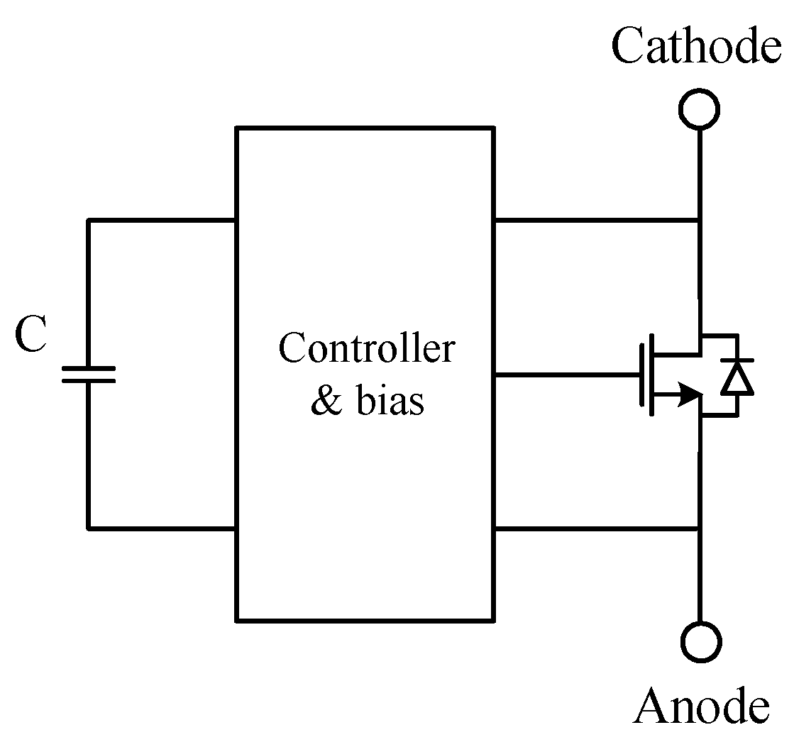
2.5. Active Bypass Diode

Instead of a traditional bypass diode, an active circuit—referred to as the cool bypass switch (CBS), see Figure 4—can be used to bypass a shaded string [19]. CBS installation is similar to that of a bypass diode and its operation reminds of a synchronous rectifier in that it is designed to conduct a reverse Ids current. The low on resistance of the MOSFET switch appears in parallel with the intrinsic body diode reducing conduction losses, thus, improving generation efficiency.

2.6. Hotspots

When a single cell of a certain sub-string becomes shaded, the associated bypass diode turns on to conduct the current of the neighboring substrings. However, the terminals of the shaded sub-string become “shorted” and a conductive path is established for the normally insolated cells of the “shorted” string to apply their voltage across the shaded cell and reverse bias it, as shown in Figure 5a. The operating point (OP) of the shaded cell is found at the intersection of its V–I curve and the mirror image of the combined V–I curve of the normally insolated cells (dashed), as illustrated in Figure 5b. This may cause an avalanche breakdown of the shaded cell. As the power dissipated in the shaded cell is quite significant, the shaded cell becomes thermally stressed. The heat is localized at the small area of the shaded cell and is referred to as the hot spot. The abnormal power dissipation may cause permanent thermal damage, cracking, or melting of the cell. A longer sub-string imposes higher reverse voltage and develops higher power at the hotspot. Therefore, bypassing shorter sub-strings prevents the breakdown, hotspot appearance, and damage [20].

3. Variable Structure Arrays

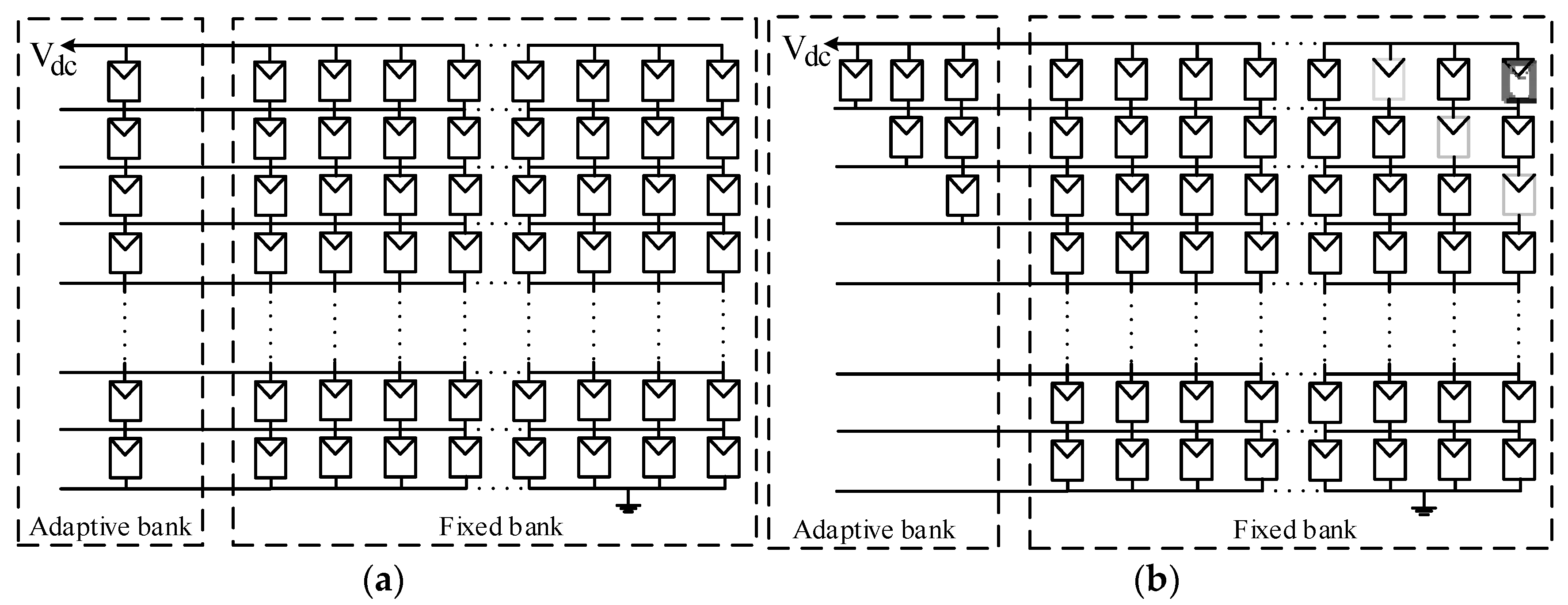
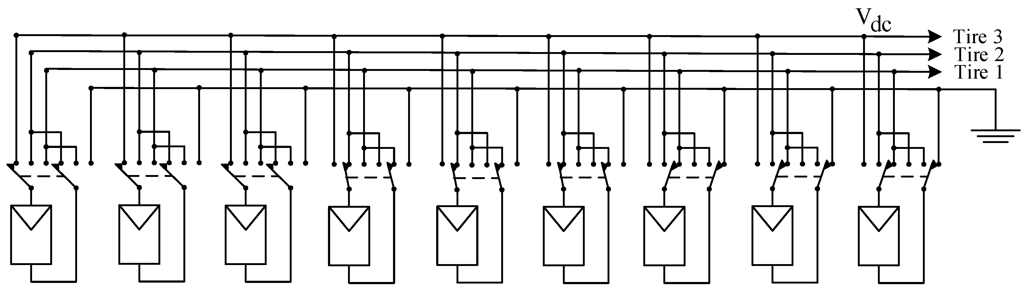
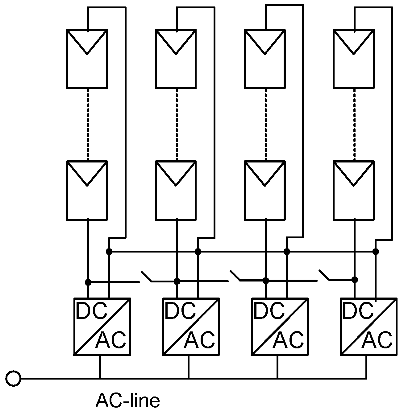
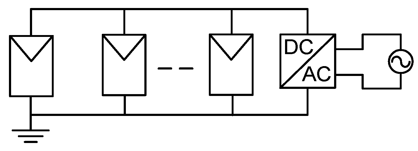
3.1. Reconfigurable Array with an Adaptive Bank

Compared to the static PV arrays discussed so far, the Dynamic PV Array (DPVA) can significantly increase the energy yield under shading conditions. DPVA, reported in [21], relies on a large, fixed TCT array; a small, totally reconfigurable, adaptive bank; and a switching matrix. The system, therefore, implements a partially reconfigurable DPVA approach.
In normal conditions, the modules of the reconfigurable array are distributed equally in parallel to the tires of the main TCT array—see Figure 6a. To equalize the energy production of the array under shading conditions, one or more PV modules from the adaptive bank are removed from the strongest tire and relocated in parallel to the weakest tire. The sorting continues until all the modules of the adaptive bank are redistributed, as in Figure 6b. Partial shading of a particular tire manifests itself by slightly decreased voltage. Therefore, electrically, the objective of the controller is to minimize the differences in voltage measured across the tires. DPVA requires additional hardware and complex sorting and control algorithms to be applied.
To implement a reconfigurable array having a hard-wired fixed part of TCT array and an adaptive one of independent solar cells, both parts were linked through a controllable matrix of switches [22]. The matrix, see Figure 7, was controlled in real time to connect the cells of the adaptive array in parallel with shaded rows of the fixed one and optimize the output power.

3.2. Dynamic Arrays

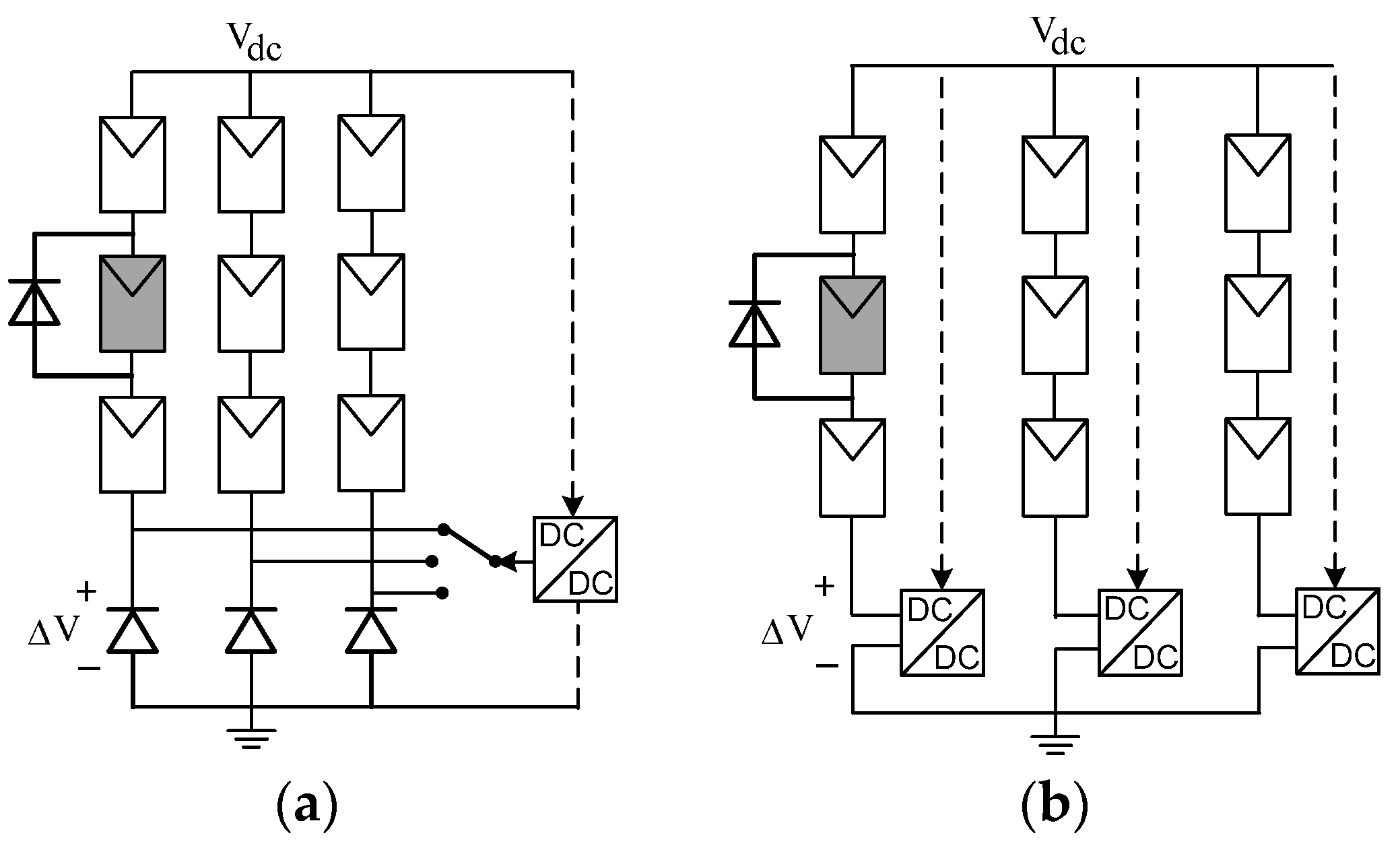
3.2.1. SC-DPVA: “String-Configured DPVA’s”

The strategy of String-Configured DPVA (SC-DPVA) [23], see Figure 8a, is configuring the normally insolated modules into SP array connected to the high dc voltage bus, whereas all the shaded modules are reconfigured into a single (parallel) tier. A step-up dc–dc converter is used to match the low voltage of the tire to the high-voltage dc bus while maximizing the power yield.

OS-DPVA “Optimized-String DPVA”

The principle of the optimized string-configured DPVA (OS-DPVA) [24] is configuring the PV modules into several strings with similar power levels. Each string connects to the dc bus through an MPPT dc–dc converter, as shown in Figure 8b. The number of strings is determined according to the number of available dc–dc converters. Under these constraints, the controller evaluates the most productive array arrangement for the given environmental conditions. As the string length is unpredictable, the input voltage to the dc–dc converter may vary widely.

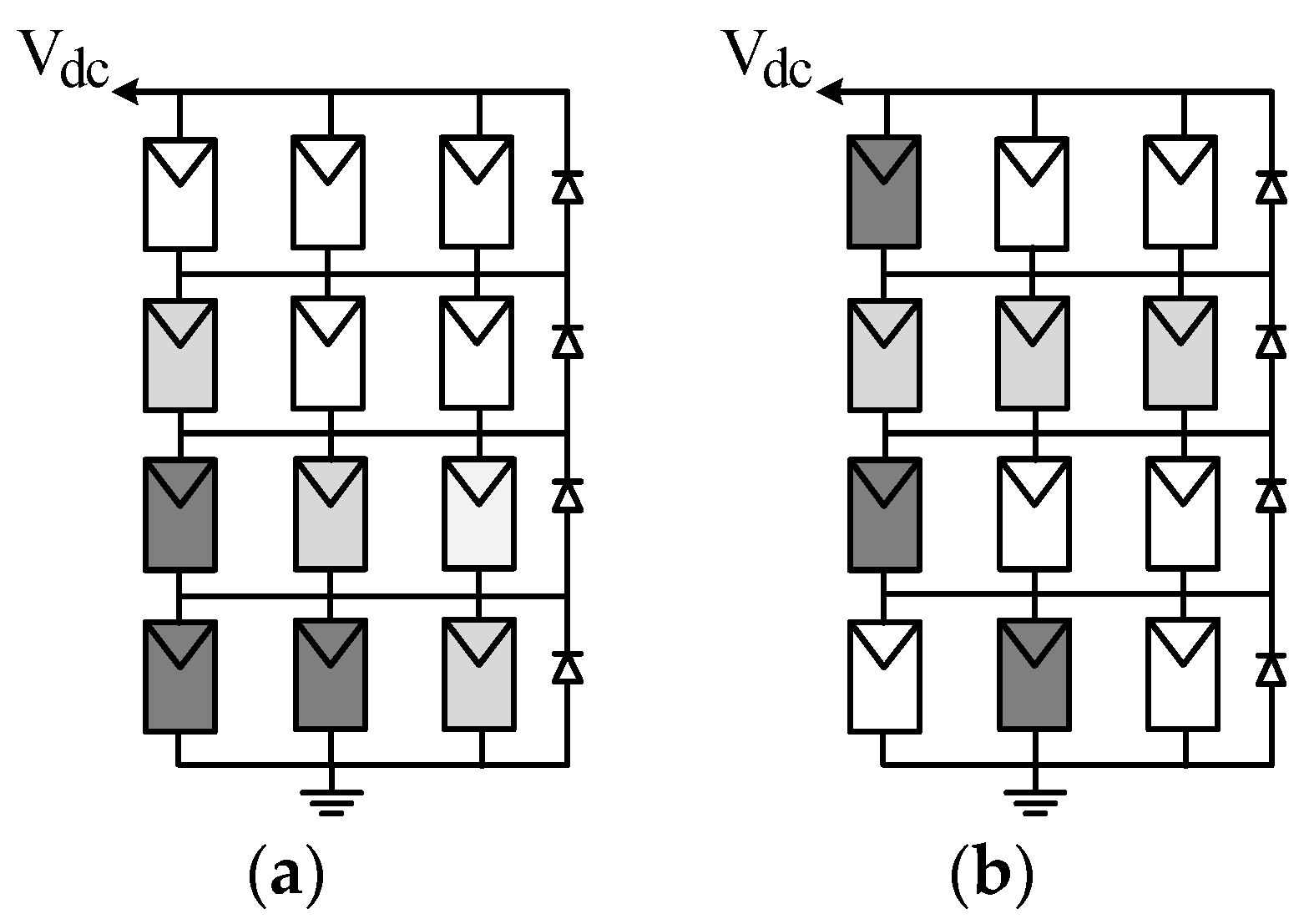
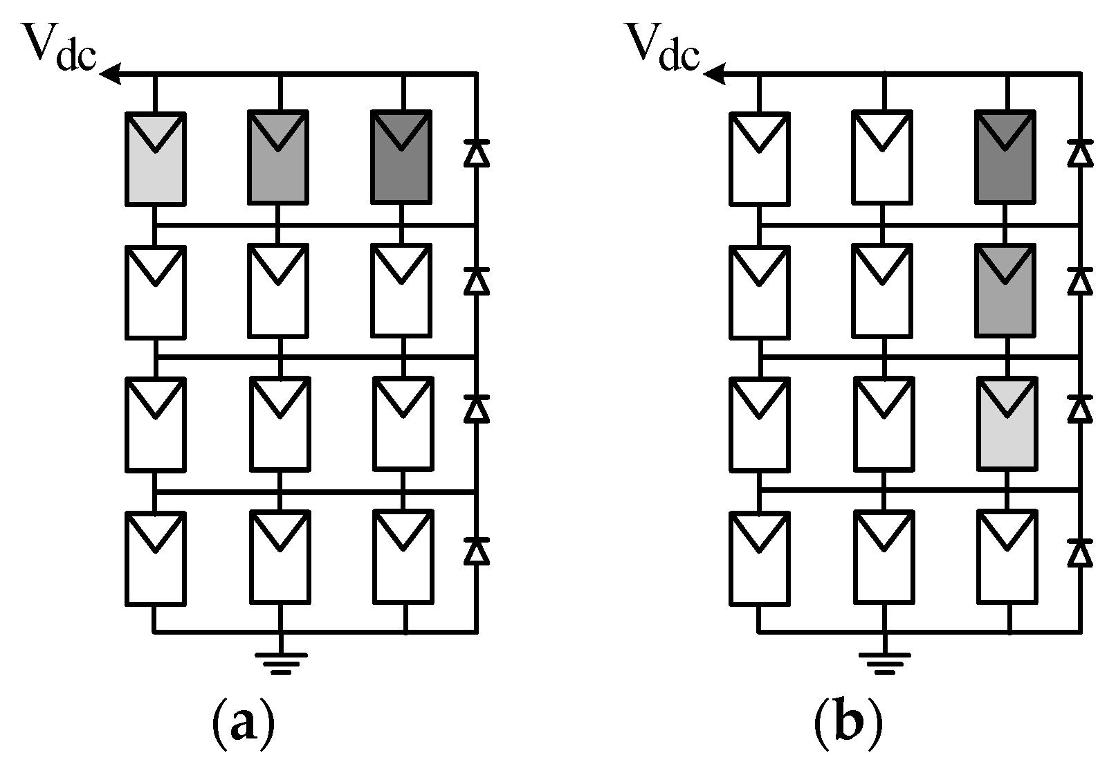
3.2.2. Reconfiguration Strategies

To optimize the productivity of the TCT array, the authors of [22] suggested reconfiguring the array to equalize tire currents. Since the photocurrent is directly proportional to the irradiation, the method also aims to do this; therefore, it also is referred to as the Irradiance Equalization (IEq). The approach is implemented by relocating modules from the best-performing tire to the weakest one until the IEq is achieved, as shown in Figure 9. The optimum irradiation of a tire can be found by averaging the total irradiation captured by the array per number of tires.
The principle of the Improved IEq strategy [24] is grouping the shaded panels of the dynamic TCT array into weak columns, as illustrated in Figure 10. Hence, the limitation from the main bulk of the array can be removed, helping to attain IEq and higher energy production.

4. Power Processing Architectures for PV Arrays

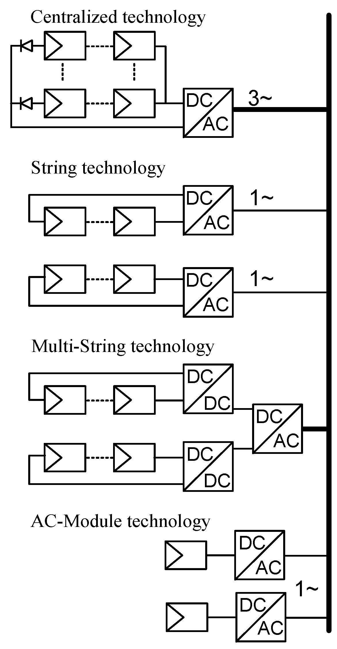
4.1. System Architectures

Another key component of any solar energy generation plant is the electronic power inverter. The inverter’s task is interfacing the solar energy to the grid. This involves maximum power point tracking (MPPT) function to maximize the captured energy, converting the dc voltage obtained from the PV array into AC, and injecting it to the grid in compliance with the high-power quality standards, i.e., at high power factor and minimum harmonic distortion. The inverter’s architecture is concerned with the implementation of a certain operational strategy of a PV array that can maximize its energy output. Four major PV inverter concepts, shown in Figure 11, are the centralized inverter, the string inverter, the multi-string inverter, and the micro-inverter [25]. The centralized inverter system is designed to connect a large SP array to the grid. SP array can provide sufficiently high voltage and high power, which justifies a three-phase grid connection with the additional advantage of reduced dc–ac power decoupling requirements.
However, as mentioned, the SP array has poor performance regarding mismatch and shading, causes difficulties in tracking the global MPPT, and has losses in the blocking diodes. The high voltage of a large SP array, though technically convenient for the generation of grid-level voltage, also poses a high-voltage hazard. Because of these demerits, the centralized inverter architecture is becoming less popular.
The string inverter [26] is designed to serve a single string of PV modules—the S array. The high voltage of the S array and operation at reduced power level results in a simpler technological solution. Another advantage of this approach is that the blocking diodes can be removed sparing the associated losses. However, the S array has the lowest tolerance to mismatch and shading. To overcome this deficiency, a variety of equalizer circuits were developed, as described below.
The multi-string inverter approach realizes the idea of an active SP array. Here, paralleling of the multiple strings is implemented through paralleling the outputs of dc–dc converters. The dedicated dc–dc converter per string can perform the MPPT function more effectively than the centralized inverter and allows voltage step-up. Hence, shorter strings can be used. The dc–dc converter also attains good matching to the common dc bus under all operating conditions and alleviates the mismatch problems between the strings. The multi-string inverter concept also provides a limited option for future expansion and system upgrades.
The TEAM concept [26] can be applied to multi-string inverters. With this concept, the master inverter and several slave inverters can share their PV strings using only a limited number of switches on the dc bus, as shown in Figure 12. In normal conditions, each inverter operates independently of its PV string under its MPPT and generates close to its rated power. Under a lower insolation level, the master can shut down one or several slaves while assigning their PV strings to the input of the adjacent slave. At very low insolation, only the master inverter remains operational. Shutting down the slaves allows inverter losses to be reduced and helps to improve the system’s efficiency at lower irradiation levels.
The AC module also referred to as module-integrated converter (MIC) or just micro-inverter is a dedicated low-power dc–ac inverter designed to interface a single PV module directly to the grid [27]. MIC has all the control, MPPT, and protection features onboard similar to the large, centralized inverter. Direct grid connection virtually creates a parallel PV array with decoupled individual modules. Hence, the poor performance of one module does not affect the performance of the rest of the array. This allows each module to be exploited to its highest potential. The additional advantage is the relative ease and practically limitless option for system expansion. Solar panels of different manufacturers can be combined without any mismatching concerns. Moreover, MIC PV arrays can be positioned to face several different directions and suits split-level and multi-pitched roofs. The main demerits of MIC are its higher cost per watt and limited reliability problem. The former issue is a result of the high-voltage step-up requirement, which necessitates additional power processing and dedicated control, while the latter issue arises mainly due to the limited lifetime of dc–ac decoupling electrolytic capacitors when exposed to the harsh field conditions of PV installations. Recent developments show promising solutions to the aforementioned problems at the cost of further increased hardware complexity [28]. The future expectations are that the increasing popularity of MICs and their growing production volume can bring the prices down to a lower level [29].
The PV-wire-free system [30], shown in Figure 13, attempts to optimize the performance and cost of a PV system by applying two key principles. Firstly, the PV-wire-free inverter system is configured to serve a single tire—the P array. The high redundancy of the P array successively resolves the shading problems. The P–V curve of the P array also has a single peak, which alleviates the MPPT task. Secondly, the PV-wire-free inverter was conceived to use aluminum current-carrying mounting frames, which combine the functions of mechanical support with those of electrical connection and using click-on-click-off dual-purpose clamps. Thus, cables and junction boxes can be spared while also reducing installation time and cost. The low dc voltage poses no electrical shock hazard, either. The major challenge, however, is in inverter design, which is required to accept low voltage at high current at its input bus and provide high-voltage step-up for proper grid interconnection.
Due to their lower switch voltage stresses and higher quality of output waveform, multilevel inverters have become increasingly popular in recent years [31]. The cascaded H-bridge multilevel inverter relies on modular design and requires multiple isolated sources, which may be equal or unequal in their magnitude. This feature is particularly suitable for PV applications where multiple PV arrays can be used as isolated dc sources [32]. Grid-connected three-phase modular multilevel converter for a large-scale multi-string photovoltaic energy conversion system is illustrated in Figure 14 [33]. The idea can be regarded as a combination of centralized and multi-string approaches. The PV strings were composed by the series connection of several PV modules, to reach the desired voltage level and then paralleled, via the dc–dc stages, to meet the desired power rating of the power plant. The power balance of the PV arrays was attained by choosing an appropriate modulation strategy.

4.2. String PE Architecture

4.2.1. Series Compensation

The SP array of a centralized inverter can be modified by applying the strategy of series voltage compensation [34]. When a module within a string is shaded, it becomes shorted by its bypass diode; therefore, the string voltage drops by a certain ΔV. Upon detection of the event and using a commutation relay, a low-power dc–dc converter can be introduced in series with a weak string—see Figure 15a. The series dc–dc converter (fed off the bus voltage Vdc) can lift its output voltage to compensate for the required voltage difference ΔV and restore the voltage of the problematic string. This allows the energy generation capability of the rest of the string to be exploited. A modification of this scheme, having a dedicated converter per string, was introduced by [35] applying a converter per string, as in Figure 15b. This solution eliminates the blocking diodes, the relays, and their associated controls and provides for greater flexibility, yet, at the cost of multiple power stages. A similar concept of a PV balancer was investigated by [36].

4.2.2. Shunt Compensation

The series compensator can match a shaded string to the DC bus, but cannot match the individual modules within the string. The latter objective can be accomplished by applying shunt compensation, which attains better performance and, therefore, prevails over the series compensation technique. As a result of intense research effort, many shunt-type compensators, also known as equalizers, were developed.
One of the earlier attempts to alleviate mismatch and shading problems and improve the energy production of a PV array is described in [37]. Two generalized topologies of a Generation Control Circuit (GCC) were discussed—see Figure 16. The idea was to remove the limitation posed by the low current output of a weak/shaded module by paralleling each module in a PV string with a dependent source. The dependent sources are supposed to provide the current difference required to eliminate the current mismatch between the modules. GCCs can be distinguished based on their energy handling strategy. Type A GCC uses unidirectional sources and feeds off the dc bus to generate the required compensation currents and the associated compensation power, whereas the Type B GCC runs on autonomous power. The latter implies that each dependent source can sink or source current. A fraction of the power drawn off the strongest modules is then returned as the compensation power to support the weak modules. This also implies that local energy storage with some means of power flow control is needed to establish a true power balance.
A full-bridge converter with multiple outputs was presented as an example of the Type A GCC—see Figure 17a. This circuit uses ordinary full-bridge rectifiers with unidirectional power flow and preferentially supplies power to a shaded PV module, for which the voltage tends to be lower. Thus, the circuit can inherently alleviate the mismatch and shading effects without the need to apply individual sensing and control functions. As an example of Type B GCC, a multi-stage chopper in Figure 17b was suggested. The chopper has n switches in the string, one per PV panel. The controller turns on all but one switch at a time. Therefore, n switching states are observed within the switching cycle.
The volt–sec balance dictates that the average voltage across the kth PV module, Vk = D’kVout, relates to the dc bus voltage, Vout, and the off-duty cycle, D’k, of the switch Sk. Fine-tuning the duty cycle, D’k, the voltage across each module in the string can be individually adjusted to its true MPP.
The power loss of a PV string to partial shading can be minimized by applying low-power dc–dc converters, which can “shuffle” power around a problematic module. The converters are wired in overlapping arrangement to shuffle power one level up, as illustrated in Figure 18 [38]. The shuffling converter has to process only the small difference between the powers generated by the adjacent modules. Therefore, while the shuffling converters can significantly increase the power generation under shading conditions, the converter losses have only a marginal effect on the overall system efficiency. However, in the worst case of mismatch, when the PV module has lost all of its generation capacity, the power shuffled by a converter equals that of a PV module so the converter must be rated accordingly. Since the system in Figure 18 is composed of unidirectional converters, it also requires an isolated converter unit to shuffle power from the top to the bottom of the string. The top-to-bottom shuffling unit can be spared when using bidirectional converters such as non-isolated Cuk or buck-boost/flyback converters [39].
The mismatch losses in a PV string can be alleviated by restoring the symmetry among its PV modules, i.e., equalization of the V–I curves of all the modules within a string. Alternatively, the required current difference can be provided by parallel power converters regulated so that the current of each module–converter pair equals the same value. The associated power can be drawn from the dc bus; hence, the approach was termed the Returned Energy Current Converter (RECC) [40]. RECC units can be implemented either as gyrators, see Figure 19, or transformers. The gyrator approach implements a kind of Norton equivalent to the Type A GCC in Figure 17a. In the experiments, multiple flyback converters were used, switched by the same PWM signal; however, they were enabled one at a time.
The concept of a switched capacitor PV equalizer [41] seems to be borrowed from [42,43]. Each equalizer cell, see Figure 20, is composed of four semiconductor switches and a flying capacitor, and is installed in parallel to a pair of adjacent PV modules. The circuit employs a modular approach and can be extended as necessary to equalize long strings. Since the switching arrangement is bidirectional, it allows the flying capacitor of the strong module to be charged and discharged in parallel to the weak module, realizing the power shuffling idea and equalizing the voltage across the adjacent modules. Eventually, due to the overlapping configuration of the equalizer cells, the entire string is equalized. A possible advantage of this approach is the “inductor-less” and loss-less zero-current switching that may be achieved due to interaction with stray inductances of the wiring cables [44].
To operate each PV module at its MPP, the differential power processing scheme [45] can be implemented using a bi-directional buck topology connecting string nodes to the main bus, as in Figure 21a, bi-directional buck-boost connected between neighboring nodes, as in Figure 21b, or bi-directional flyback converters interfacing each module with the main bus, as in Figure 21c. Converters in Figure 21a,c realize the Type A GCC whereas, Figure 21b can be classified as Type B GCC.
The bi-directional flyback scheme in Figure 21c has the merit of an independent duty cycle which can be moderated by proper design choice of coupled inductor turn ratio. The scheme in Figure 21a includes a chain of overlapping, but independent buck-boost converters. Since the input and output voltages of each unit are nearly equal, the duty cycle remains about the comfortable value of 0.5. Compared to rather narrow off-duty cycle, D’k, of GCC in Figure 21b, which has to comply with the constrain k D k   =   1 . Operation at extreme duty cycle penalizes the converter’s efficiency and is undesirable. The bi-directional buck scheme, in Figure 21a, is also problematic as converters at the bottom of the string operate at a very narrow duty cycle. Yet, the differential converters are operated only when needed, that is, when a mismatch occurs, and are required to compensate for the usually small current differences between the MPP currents and, therefore, they process only a fraction of total power. This means that the impact of the converter’s losses on the overall system’s efficiency is marginal.
However, shunt compensation schemes, similar the ones shown in Figure 21c, using unidirectional flyback converters were also suggested [45,46,47,48].
A single inductor buck-boost chopper was presented in [49]. The switching network of the chopper, see Figure 22, allows the inductor to be charged from any unshaded module and discharged in parallel to a shaded module anywhere in the string, thus supporting and equalizing the currents at each junction. Implementing the idea required a unidirectional current flow; hence, diodes were placed in series with the switches. The flexibility of the system allows for a variety of switching strategies [49,50,51].
A single switch voltage equalizer based on a SEPIC converter with multiple stacked output sections with a capacitive coupling arrangement was presented in [52]. The equalizer requires only one switch regardless of the number of PV modules in the string—see Figure 23. This greatly simplifies the hardware as well as the control effort.
A voltage equalizer, based on an asymmetric half-bridge series-resonant inverter and a capacitive voltage multiplier as a multi-output stage, see Figure 24, was proposed by [53]. The even voltage distribution between the multiplier stages helps to equalize the voltages across the PV modules. The circuit requires only a pair of switches and can attain high efficiency due to lossless ZV switching.
A combined approach applying series-shunt compensation techniques was suggested to balance an SP array [54]. Shunt current compensation converters provide compensation of modules within a string whereas, the series voltage converter matches the string voltage to the input bus of a centralized inverter—see Figure 25. The motivation was that, in a large SP array, equalizing only the voltage across the modules in a string is not enough as it may still operate apart from MPP due to irradiation differences across the various strings. With the combined compensation scheme, authors can claim a higher energy yield.
Based on field studies, ref. [55] has detailed a simulation-based approach to size the differential power processing converter power ratings. For a system of 15 subpanel PV elements, the analysis identified 15–17% PV-to-bus converters and 23–33% PV-to-PV converters as appropriate power ratings. During 25 years of operation, DPP architecture is expected to deliver up to 2.8% more total energy than a conventional string inverter configuration.

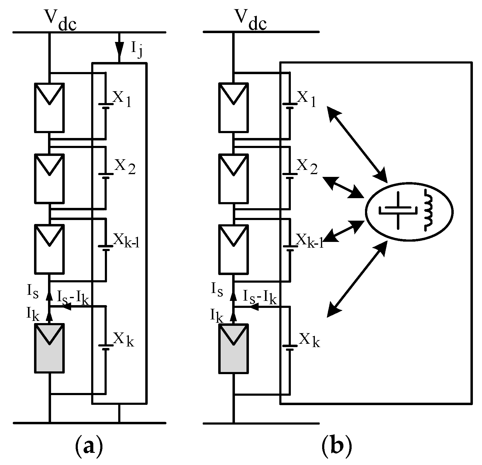
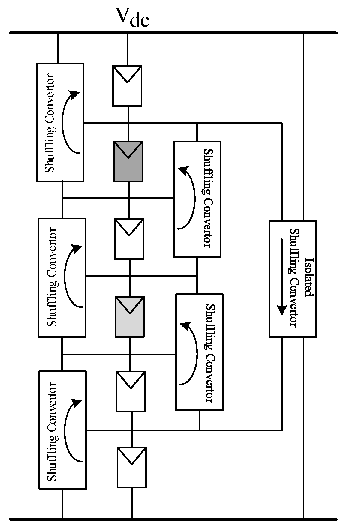
4.3. Module-Integrated Architectures

Application of a dedicated converter per each PV module is referred to as Module-Integrated Converter (MIC). MIC is individually controlled by the MPPT controller to extract the optimal amount of available power from each PV module and help to resolve mismatch and shading problems. MICs that are employed as dc–dc converters are referred to as dc optimizers, whereas MICs with a dc–ac inversion capability can be connected directly to the grid and are commonly referred to as micro-inverters. Compared to equalizers, which process only part of the power needed to balance the PV array, MICs process the full power of the array and are at disadvantage. For these reasons, MICs have to exhibit the highest efficiency, whereas the requirements towards the equalizer’s performance are significantly relaxed.
The outputs of a dc optimizer can be connected in series to form a string—see Figure 26a. Such a configuration is termed as a cascaded connection [55,56,57]. Series-connected dc optimizers can achieve a higher voltage suitable for grid-connected systems. Within such a string, each optimizer can operate at near unity conversion ratio, require no transformers, and allows the application of cheap, low-voltage components, such as low Ron MOSFETs and Schottky diodes, which helps to attain a high level of efficiency.
DC optimizers can also be connected in parallel [58,59] to a common DC bus, as in Figure 26b. Paralleled optimizers can provide high currents at a relatively low voltage, have excellent tolerance to shading, and are well suited for battery charging applications. Paralleled optimizers for grid-tied applications require high-voltage MOSFETs, with higher on resistance and high-voltage, ultra-fast recovery diodes, as well as high-voltage capacitors and larger inductors. Therefore, compared to cascaded optimizers, the parallel optimizers are at a performance–cost disadvantage.
The two-stage approach, see Figure 26c, can be implemented for standalone dc loads; however, this will add costs and impair efficiency. Yet, the wider output voltage range and possible isolation features added by another conversion stage may be an advantage that outweighs the disadvantages [60].
A string of cascaded MICs operating together poses a control problem. Two primary control objectives of an MIC are performing the MPPT function and generating an output current that tightly follows the string current. Decoupling the control functions of multiple MICs can be attained by applying a two-loop control approach [61]. The inner voltage loop of each MIC is dedicated to MPP tracking, whereas the outer current loop follows the string current commanded by the downstream grid-tied inverter. To generate the desired string current, each MIC inherently finds an appropriate operating point along its power curve and outputs a corresponding output voltage—see Figure 27. The downstream inverter then can regulate the string voltage by varying the string current to adjust the ac power injected into the grid to the array’s MPP.

4.4. Sub-Module-Integrated Architectures

PV modules are pre-wired, field-installable units fabricated in a variety of sizes and rated voltage and power output. To date, the 36- and 72-cell PV modules are the industry standards for large power production [61,62,63]. Most commercially available PV modules are configured as a short string of a few, usually three, sub-strings, each having a bypass diode across. Each sub-string is configured as an SP array of macro-PV cells. Therefore, various approaches developed for string and module levels can also be applied to optimize power output from each sub-string within a PV module. The incentive to the investigation of sub-module architectures remains increasing the energy yield of a PV module by reducing the limitations set by mismatch and partial shading. Operation at the sub-string level also eliminates the bypass diodes. As mentioned, in absence of the bypass diodes the P–V characteristic of the module has only a single distinct peak, which can be easily and precisely tracked by simple MPPT algorithms.
The primary difficulty in the implementation of the sub-string power processing schemes is the lower dc voltage and the higher voltage step-up required. Additionally, the system’s cost tends to be higher due to multiple identical blocks. However, the sub-string power stage can be implemented using low-voltage, low-power, cheap components. In case the sub-string power processors become popular in the future, they may benefit from cost reduction due to mass production, particularly if the power converters can be fabricated during the PV panel manufacturing process.
The Dynamic Macro-Cell Array [64] is reconfigurable and can implement the idea of irradiance equalization. PV macro-cells, as shown in Figure 28a, can be reconfigured into a TCT array of flexible length and width using bidirectional semiconductor switches—see Figure 28b. The incorporation of a macro-cell into a tire is accomplished by closing the switches SP1 and SP2 while keeping the switch SS open. Opening switches SP1 and SP2 terminates the tire, while closing switch SS establishes a connection to the next-level tire. Therefore, several weak macro-cells can be grouped into a single tire to match the current of a neighboring tire of just a few stronger macro-cells, as illustrated in Figure 28c. The advantage of the proposed architecture is that such a switching matrix can be implemented and embedded into the structure of the PV panel by the manufacturer.
A MIC connecting a single PV module to a grid operates off three series substrings, as in Figure 29a. Hence, the idea of distributed power processing could be further taken to a sub-module level (subMIC) [65]. Each sub-string of the PV module can be provided with a dedicated subMIC to directly connect to the grid, as in Figure 29b. However, submodule level microinverters are not practical today due to the high hardware cost and relatively low efficiency associated with the large voltage step-up required.
These difficulties can be alleviated by implementing the two-stage solution shown in Figure 29c. This involves providing each sub-string with either a cascaded dc–dc optimizer [65] or an equalizer [66] and a single grid-tied microinverter to connect the entire PV module to the grid. This approach has the merit of all the PV cell strings working on their MPP regardless of a mismatch case.
The multiple-input boost converter, as shown in Figure 30, involves reorganizing the PV panel macro-cells into two separate sub-strings and realizing a parallel power processing scheme [67]. Since each section of the multi-input boost is operated with a different duty ratio, D1, and D2, the input currents are decoupled, and an independent MPPT can be implemented for each sub-string. The parallel connection entails relatively simple control; however, in cases where a high-voltage output is required, the efficiency and cost are compromised.
A substring-cascaded scheme, similar to the one shown in Figure 31a, was proposed by [68] and utilized synchronous buck converters operated at near-unity gain. Such a configuration can attain independent MPPT for each sub-string, requires lower rating devices and, potentially, can achieve the highest switch utilization and a high efficiency and low cost.
Isolated-port subMIC architecture with substring equalizer analogous to type B GCC was reported by [69]. This architecture has several advantages. Firstly, it is the reduced power rating of the subMIC. Secondly, the subMiCs’ conversion ratio can be selected at the designers’ convenience to attain optimization of magnetics and efficiency. Thirdly, active filtering can be implemented with an energy storage capacitor on the subMIC isolated port, reducing the cost and improving the efficiency of downstream power electronics.
An original idea, patented by [42], suggested integrating a switched capacitor equalizing network within the PV module. The flying capacitors are switched between two neighboring rows (tires) of macro-cells, resulting in the voltage across each row being substantially equal to the voltage across every other row. Hence, the power shuffling scheme can be realized to cope with partial shading, mismatch, and mechanical failure conditions.
An optimized submodule-level DMPPT system with a flexible time-sharing maximum current-point-tracking algorithm that detects the output current of series-connected dc–dc converters [69] guarantees that each of the PV submodule outputs individual true maximum power, regardless of irradiance, and eliminates the need for several MPPT units and current sensors in the system.

5. Emerging Multi-Junction and Concentrated PV

A substantial increase in PV conversion efficiency can be achieved by collecting solar irradiation at a wider spectrum. This concept can be implemented with the application of Multi-Junction (MJ) cells composed of several PV sub-cells, which have distinct spectral responses. Two common types of MJ cells are the Vertical Multi Junction (VMJ) and Lateral Multi Junction (LMJ) cells. A conversion efficiency reaching 50% was reported [70,71]. The VMJ architecture uses an independently contacted vertical junction stack of PV sub-cells, as illustrated in Figure 31a. The LMJ architecture applies optics to split the incoming solar spectrum and focuses each color band onto a sub-cell with the appropriate responsivity, as illustrated in Figure 31b.
The spectral response of the sub-cell is a function of the bandgap energy, Eg, which, in turn, is determined by materials used to manufacture the sub-cell. Sub-cells made of different materials and have different V–I curves; therefore, they pose an interconnected challenge: series connection can result in a current mismatch, whereas parallel connection can result in voltage mismatch. Since each sub-cell in the MJ structure is accessible, to avoid mismatch, sub-cells with the same bandgap energy can be grouped to form a sub-string. The same number of sub-cells can be configured into SP sub-strings of different lengths and widths to approximately equalize their open-circuit voltage and current. This allows the application of distributed MPPT concepts. For instance, a multi-input converter can be used to process power [72]. Alternatively, dc optimizers can be used [72,73,74] with their outputs in series or parallel, as in Figure 32, to provide the output of the PV module.
The Concentrated Photovoltaic System (CPV) applies optical means to capture and concentrates solar energy onto a tiny PV cell. Several low-profile advanced optical structures developed for CPV systems are illustrated in Figure 33 [75]. An illumination intensity of 1000 SUN is not uncommon for CPV. Presently, CPV systems are based on III-IV MJ cells [75,76,77] with high responsivity over a broad range of wavelengths, from 300 to 1800 nm. CPV outperforms Si, attaining efficiencies in excess of 40% (vs. ~15% for Si). CPV also has a lower temperature coefficient than Si, resulting in lower voltage and power droop with an increasing temperature. The primary disadvantages of CPV are its heat management and the need to maintain alignment with the sun. The latter implies that CPV should be deployed using a dual-axis mechanical tracker, which is a bulky and costly piece of equipment that also requires maintenance [78]. A solar tracking mechanism can also be used with simple PV panels to improve the energy yield; yet, as the cost of solar panels plunges, the solar trackers are becoming less popular in such applications simply because it is cheaper and more practical to install a larger solar array.
To attain high voltage and power, CPV cells are stacked into large arrays and are subject to mismatch problems due to different material types, parameter variation, misalignment, non-uniform aging, etc. To resolve the problem, a high-granularity DMPPT approach has been implemented for the CPV array [79]. Each CPV sub-module was equipped with a bidirectional shuffling equalizer and an MPPT-controlled optimizer. The optimizers’ outputs were connected in series to the centralized inverter input bus. The system yielded significant power benefits.
Since the concentrator solar stations provide a very high energy density for their solar modules, their thermal operating conditions deserve special attention. Modern methods of cooling should be applied to avoid thermal damage, improve the operating conditions of the solar modules and increase conversion efficiency. In such systems, it also makes sense to use solar photovoltaic thermal modules. Such modules have relatively stable parameters at a constant thermal regime, high overall efficiency, and can be used to generate both power and heat and, accordingly, can increase the overall efficiency of this kind of system [79,80].

6. Adoption by the Public

As the technology of PV energy generation is coming out of age, solar energy generation plants of different sizes and power capacities are becoming increasingly popular. For many years, very small-scale PV systems, of about ×100 W, were used by boats or cabin owners for their recreational activities. In the last two decades, however, a substantial change in proliferation of the solar systems occurred due to the encouraging government policies of many countries. Small-scale residential rooftop PV systems in the range of 5–15 kW are being installed by some homeowners. This trend has continued to grow; as such a system not only covers the electricity bills of the household, but can also bring profits to the owners. For the same reasons, some commercial and industrial corporations that have larger office buildings and production facilities can accommodate medium-scale 50–150 kW rooftop PV systems that are becoming commonplace, whereas large-scale ground-based solar power plants with a capacity of about 500 kW can be installed in large parking lots. Higher power solar plants in the 1–5 MW range can be installed on farms, especially in rural areas, where the land cost is affordable [81,82,83], particularly in the sunlight-rich desert areas with low agricultural yield.
Thus, it seems that solar power technologies are facing a bright future in the energy market.

7. Summary

The growing awareness of the environmental problems caused by coal-fired power plants has made alternative energy generation the focus public attention. Once considered questionable, PV energy generation is here to stay, and will seize a significant share of the future energy market. Recent advances in PV technology have resulted in major improvements to power generation efficiency, as well as its economic viability. This paper presents a survey of the up-to-date architectures of PV systems and reviews the concepts and strategies of their associated electronic power processors to reveal the state of the art and provide a reference for scientists, designers, and engineers. As shown, various alternatives are available for each component of a solar-PV plant: cell technology (single crystalline vs. polycrystalline vs. thin film), concentration level (from non-concentrated through low concentrated, up to highly concentrated CPV), architecture topology, and electronic power processors. The design choices among this variety of alternatives may greatly affect a system’s performance parameters, such as yearly energy yield, reliability, maintainability, and safety. It will also manifest in a system’s initial cost and operational cost. There is no universal optimal choice as it depends on installation-specific characteristics, such as irradiance and ambient temperature profiles, and uniformity (large PV arrays in rural areas versus urban rooftop installations, versus build-in PV systems). Therefore, detailed designs must be compared as per their installation.

Author Contributions

Conceptualization, D.S. and A.A.; investigation, A.A.; resources, D.S.; data curation, A.A.; writing—original draft preparation, A.A.; writing—review and editing, A.A.; visualization, A.A.; supervision, project administration, and funding acquisition, D.S. All authors have read and agreed to the published version of the manuscript.

Funding

This research received no external funding.

Institutional Review Board Statement

Not applicable.

Informed Consent Statement

Not applicable.

Data Availability Statement

Not applicable.

Conflicts of Interest

The authors declare no conflict of interest.

References

  1. The Nobel Prize in Physics 1921. Available online: https://www.nobelprize.org/prizes/physics/1921/summary/ (accessed on 8 August 2021).
  2. Solar Cell Central. Solar Electricity Costs. Available online: http://solarcellcentral.com/cost_page.html (accessed on 8 August 2021).
  3. Photovoltaic System. Available online: https://en.wikipedia.org/wiki/Photovoltaic_system (accessed on 8 August 2021).
  4. Esram, T.; Chapman, P.L. Comparison of photovoltaic array maximum power point tracking techniques. IEEE Trans. Energy Convers. 2007, 22, 439–449. [Google Scholar] [CrossRef] [Green Version]
  5. Trends in PV Applications 2020. Available online: https://iea-pvps.org/trends_reports/trends/ (accessed on 8 August 2021).
  6. Kajihara, A.; Harakawa, A.T. Model of photovoltaic cell circuits under partial shading. In Proceedings of the 2005 IEEE International Conference on Industrial Technology, Hong Kong, China, 14–17 December 2005; pp. 866–870. [Google Scholar]
  7. Feldman, J.; Singer, S.; Braunsten, A. Solar cell interconnections and shadow problem. Sol. Energy 1981, 26, 419–428. [Google Scholar] [CrossRef]
  8. Wang, Y.J.; Hsu, P.C. An investigation on partial shading of PV modules with different connection configurations of PV cells. Int. J. Energy 2011, 36, 3069–3078. [Google Scholar] [CrossRef]
  9. Bishop, J.W. Computer simulation of the effects of electrical mismatches in photovoltaic cell interconnection circuit. Solar Cells 1988, 25, 73–89. [Google Scholar] [CrossRef]
  10. Moballegh, S.; Jiang, J. Modeling, Prediction, and Experimental Validations of Power Peaks of PV Arrays Under Partial Shading Conditions. IEEE Trans. Sustain. Energy 2014, 5, 293–300. [Google Scholar] [CrossRef]
  11. Storey, J.; Wilson, P.R.; Bagnall, D. Simulation platform for dynamic photovoltaic arrays. In Proceedings of the 2013 IEEE Energy Conversion Congress and Exposition (ECCE 2013), Denver, CO, USA, 15–19 September 2013; pp. 1617–1622. [Google Scholar]
  12. Gao, L.; Dougal, R.A.; Liu, S.; Iotova, A.P. Parallel-Connected Solar PV System to Address Partial and Rapidly Fluctuating Shadow Conditions. IEEE Trans. Ind. Electron. 2009, 56, 1548–1556. [Google Scholar]
  13. Teo, J.C.; Tan, R.H.; Mok, V.H.; Ramachandaramurthy, V.K.; Tan, C. Impact of Partial Shading on the P-V Characteristics and the Maximum Power of a Photovoltaic String. Energies 2018, 11, 1860. [Google Scholar] [CrossRef] [Green Version]
  14. Maki, A.; Valkealahti, S. Power Losses in Long String and Parallel-Connected Short Strings of Series-Connected Silicon-Based Photovoltaic Modules Due to Partial Shading Conditions. IEEE Trans. Energy Convers. 2012, 27, 173–183. [Google Scholar] [CrossRef]
  15. Gautam, N.K.; Kaushika, N.D. Network analysis of fault-tolerant solar photovoltaic arrays. Sol. Energy Mater. Solar Cells 2001, 69, 25–42. [Google Scholar] [CrossRef]
  16. Díaz-Dorado, E.; Suárez-García, A.; Carrillo, C.; Cidrás, J. Influence of the shadows in photovoltaic systems with different configurations of bypass diodes. In Proceedings of the 2010 International Symposium on Power Electronics Electrical Drives Automation and Motion (SPEEDAM), Pisa, Italy, 14–16 June 2010; pp. 134–139. [Google Scholar]
  17. Silvestre, S.; Boronat, A.; Chouder, A. Study of bypass diodes configuration on pv modules. Appl. Energy 2009, 86, 1632–1640. [Google Scholar] [CrossRef]
  18. Miyatake, M.; Toriumi, F.; Endo, T.; Fujii, N. A Novel maximum power point tracker controlling several converters connected to photovoltaic arrays with particle swarm optimization technique. In Proceedings of the European Conference on Power Electronics and Applications, Aalborg, Denmark, 2–5 September 2007; pp. 1–10. [Google Scholar]
  19. Boztepe, M.; Guinjoan, F.; Velasco-Quesada, G.; Silvestre, S.; Chouder, A.; Karatepe, E. Global MPPT Scheme for Photovoltaic String Inverters Based on Restricted Voltage Window Search Algorithm. IEEE Trans. Ind. Electron. 2014, 61, 3302–3312. [Google Scholar] [CrossRef]
  20. Acciari, G.; Graci, D.; La Scala, A. Higher PV module efficiency by a novel CBS bypass. IEEE Trans. Power Electron. 2011, 26, 1333–1336. [Google Scholar] [CrossRef]
  21. Swaleh, M.S.; Green, M.A. Effect of shunt resistance and bypass diode on the shadow tolerance of solar cell modules. Sol. Cells 1982, 5, 183. [Google Scholar] [CrossRef]
  22. Dzung, N.; Lehman, B. An Adaptive Solar Photovoltaic Array Using Model Based Reconfiguration Algorithm. IEEE Trans. Ind. Electron. 2008, 55, 2644–2654. [Google Scholar]
  23. Velasco-Quesada, G.; Guinjoan-Gispert, F.; Pique-Lopez, R.; Roman-Lumbreras, M.; Conesa-Roca, A. Electrical PV Array Reconfiguration Strategy for Energy Extraction Improvement in Grid-Connected PV Systems. IEEE Trans. Ind. Electron. 2009, 56, 4319–4331. [Google Scholar] [CrossRef] [Green Version]
  24. Storey, J.; Wilson, P.R.; Bagnall, D. The Optimized-String Dynamic Photovoltaic Array. IEEE Trans. Power Electron. 2014, 29, 1768–1776. [Google Scholar] [CrossRef] [Green Version]
  25. Storey, J.P.; Wilson, P.R.; Bagnall, D. Improved Optimization Strategy for Irradiance Equalization in Dynamic Photovoltaic Arrays. IEEE Trans. Power Electron. 2013, 28, 2946–2956. [Google Scholar] [CrossRef]
  26. Kjaer, S.B.; Pedersen, J.K.; Blaabjerg, F. A review of single-phase grid connected inverters for photovoltaic modules. IEEE Trans. Ind. Appl. 2005, 41, 1292–1306. [Google Scholar] [CrossRef]
  27. Myrzik, J.M.A.; Calais, M. String and module integrated inverters for single phase grid connected photovoltaic systems–A review. In Proceedings of the 2003 IEEE Bologna Power Tech Conference, Bologna, Italy, 23–26 June 2003; Volume 2. [Google Scholar]
  28. Yogesh, R.N.; Thorat, A.R. A review on photovoltaic module based grid connected power inverter. In Proceedings of the 2013 International Conference on Power, Energy and Control (ICPEC), Dindigul, India, 6–8 February 2013; pp. 272–276. [Google Scholar]
  29. Hu, H.; Harb, S.; Kutkut, N.; Batarseh, I.; Shen, Z.J. Power decoupling techniques for micro-inverters in PV systems-a review. In Proceedings of the 2010 IEEE Energy Conversion Congress and Exposition (ECCE), Atlanta, GA, USA, 12–16 September 2010; pp. 3235–3240. [Google Scholar]
  30. Scholten, D.M.; Ertugrul, N.; Soong, W.L. Micro-inverters in small scale PV systems: A review and future directions. In Proceedings of the 2013 Australasian Universities Power Engineering Conference (AUPEC), Hobart, TAS, Australia, 29 September–3 October 2013; pp. 1–6. [Google Scholar]
  31. Oldenkamp, H.; de Jong, I.; van der Borg, N.; de Boer, B.; de Moor, H.; Sinke, W.C. PV-Wirefree versus Conventional Pv-Systems: Detailed Analysis of Difference in Energy Yield between Series and Parallel Connected Pv-Modules. Available online: http://www.oke-services.nl/pages/pvwirefree.htm (accessed on 8 August 2021).
  32. Daher, S.; Schmid, J.; Antunes, F.L.M. Multilevel Inverter Topologies for Stand-Alone PV Systems. IEEE Trans. Ind. Electron. 2008, 55, 2703–2712. [Google Scholar] [CrossRef]
  33. Malathy, S.; Ramaprabha, R.; Mathur, B.L. Asymmetrical multilevel inverters for partially shaded PV systems. In Proceedings of the 2013 International Conference on Circuits, Power and Computing Technologies (ICCPCT), Nagercoil, India, 20–21 March 2013; pp. 579–583. [Google Scholar]
  34. Echeverria, J.; Kouro, S.; Perez, M.; Abu-Rub, H. Multi-modular cascaded DC-DC converter for HVDC grid connection of large-scale photovoltaic power systems. In Proceedings of the IECON 2013—39th Annual Conference of the IEEE Industrial Electronics Society, Vienna, Austria, 10–13 November 2013; pp. 6999–7005. [Google Scholar]
  35. Mishima, T.; Ohini, T. A Power Compensation and Control System for a Partially Shaded PV Array. Electr. Eng. Jpn. 2004, 146, 74–82. [Google Scholar] [CrossRef]
  36. Karatepe, E.; Hiyama, T.; Boztepe, M.; Colak, M. Voltage based power compensation system for photovoltaic generation system under partially shaded insolation conditions. Energy Convers. Manag. 2008, 49, 2307–2316. [Google Scholar] [CrossRef]
  37. Zhou, H.; Zhao, J.; Han, Y. PV Balancers: Concept, Architectures, and Realization. IEEE Trans. Power Electron. 2015, 30, 3479–3487. [Google Scholar] [CrossRef]
  38. Shimizu, T.; Hirakata, M.; Kamezawa, T.; Watanabe, H. Generation Control Circuit for Photovoltaic Modules. IEEE Trans. Power Electron. 2001, 16, 293–300. [Google Scholar] [CrossRef] [Green Version]
  39. Walker, G.; Xue, J.; Sernia, P. PV string per-module maximum power point enabling converters. In Proceedings of the Australasian Universities Power Engineering Conference, AUPEC’03, Christchurch, New Zealand, 28 September–1 October 2003. [Google Scholar]
  40. Walker, G.R.; Pierce, J.C. Photovoltaic Dc-Dc module integrated converter for novel cascaded and bypass grid connection topologies—design and optimisation. In Proceedings of the 37th IEEE Power Electronics Specialists Conference, Jeju, Korea, 18–22 June 2006; pp. 1–7. [Google Scholar]
  41. Nimni, Y.; Shmilovitz, D. A returned energy architecture for improved photovoltaic systems efficiency. In Proceedings of the 2010 IEEEE Symposium on Circuits and Systems (ISCAS), Paris, France, 30 May–2 June 2010; pp. 2191–2194. [Google Scholar]
  42. Ben-Yaakov, S.; Blumenfeld, A.; Cervera, A.; Evzelman, M. Design and evaluation of a modular resonant switched capacitors equalizer for PV panels. In Proceedings of the Energy Conversion Congress and Exposition (ECCE), Raleigh, NC, USA, 15–20 September 2012; pp. 4129–4136. [Google Scholar]
  43. Ball, N.E. Parallel and Virtual Parallel Interconnection of Solar Cells in Solar Panel. U.S. Patent 7,521,630, 21 April 2007. [Google Scholar]
  44. Pascual, C.; Krein, P.T. Switched capacitor system for automatic series battery equalization. In Proceedings of the Applied Power Electronics Conference and Exposition, Atlanta, GA, USA, 27 February 1997; Volume 2, pp. 848–854. [Google Scholar]
  45. Yuanmao, Y.; Cheng, K.W.E.; Yeung, Y.P.B. Zero-Current Switching Switched-Capacitor Zero-Voltage-Gap Automatic Equalization System for Series Battery String. IEEE Trans. Power Electron. 2012, 27, 3234–3242. [Google Scholar] [CrossRef]
  46. Shenoy, P.S.; Kim, K.A.; Johnson, B.B.; Krein, P.T. Differential Power Processing for Increased Energy Production and Reliability of Photovoltaic Systems. IEEE Trans. Power Electron. 2013, 28, 2968–2979. [Google Scholar] [CrossRef]
  47. Zhang, Q.; Sun, X.; Zhong, Y.; Matsui, M. A novel topology for solving the partial shading problem in photovoltaic power generation system. In Proceedings of the 2009 IEEE 6th International Power Electronics and Motion Control Conference, Wuhan, China, 17–20 May 2009; pp. 2130–2135. [Google Scholar]
  48. Sharma, P.; Agarwal, V. Exact Maximum Power Point Tracking of Grid-Connected Partially Shaded PV Source Using Current Compensation Concept. IEEE Trans. Power Electron. 2014, 29, 4684–4692. [Google Scholar] [CrossRef]
  49. Debnath, D.; De, P.; Chatterjee, K. Simple scheme to extract maximum power from series connected photovoltaic modules experiencing mismatched operating conditions. IEEE Trans. Power Electron. 2016, 9, 408–416. [Google Scholar] [CrossRef]
  50. Villa, L.F.L.; Ho, T.-P.; Crebier, J.-C.; Raison, B. A Power Electronics Equalizer Application for Partially Shaded Photovoltaic Modules. IEEE Trans. Power Electron. 2013, 6, 1179–1190. [Google Scholar]
  51. Villa, L.F.L.; Pichon, X.; Sarrafin-Ardelibi, F.; Raison, B.; Crebier, J.C.; Labonne, A. Toward the Design of Control Algorithms for a Photovoltaic Equalizer: Choosing the Optimal Switching Strategy and the Duty Cycle. IEEE Trans. Power Electron. 2014, 29, 1447–1460. [Google Scholar] [CrossRef]
  52. Villa, L.F.L.; Raison, B.; Crebier, J.-C. Toward the Design of Control Algorithms for a Photovoltaic Equalizer: Detecting Shadows through Direct Current Sampling. IEEE J. Emerg. Sel. Top. Power Electron. 2014, 2, 893–906. [Google Scholar] [CrossRef]
  53. Uno, M.; Kukita, A. Single-switch voltage equalizer using multi-stacked SEPIC for partially shaded series-connected PV modules. In Proceedings of the of 35th International Telecommunications Energy Conference Smart Power and Efficiency (INTELEC), Hamburg, Germany, 13–17 October 2013; pp. 1–6. [Google Scholar]
  54. Uno, M.; Kukita, A. Two-switch voltage equalizer using series-resonant inverter and voltage multiplier for partially-shaded series-connected photovoltaic modules. In Proceedings of the 2013 IEEE Energy Conversion Congress and Exposition (ECCE), Denver, CO, USA, 15–19 September 2013; pp. 1311–1318. [Google Scholar]
  55. Sharma, P.; Agarwal, V. Maximum Power Extraction from a Partially Shaded PV Array Using Shunt-Series Compensation. IEEE J. Photovolt. 2014, 4, 1128–1137. [Google Scholar] [CrossRef]
  56. Kim, K.A.; Shenoy, P.S.; Krein, P.T. Converter Rating Analysis for Photovoltaic Differential Power Processing Systems. IEEE Trans. Power Electron. 2015, 30, 1987–1997. [Google Scholar] [CrossRef]
  57. Walker, G.R.; Sernia, P.C. Cascaded DC-DC converter connection of photovoltaic modules. IEEE Trans. Power Electron. 2004, 19, 1130–1139. [Google Scholar] [CrossRef]
  58. Femia, N.; Lisi, G.; Petrone, G.; Spagnuolo, G.; Vitelli, M. Distributed Maximum Power Point Tracking of Photovoltaic Arrays: Novel Approach and System Analysis. IEEE Trans. Ind. Electron. 2008, 55, 2610–2621. [Google Scholar] [CrossRef] [Green Version]
  59. Roman, E.; Alonso, R.; Ibanez, P.; Elorduizapatarietxe, S.; Goitia, D. Intelligent PV module for grid-connected PV systems. IEEE Trans. Ind. Electron. 2006, 53, 1066–1073. [Google Scholar] [CrossRef]
  60. Xiao, W.; Ozog, N.; Dunford, W.G. Topology study of photovoltaic interface for maximum power point tracking. IEEE Trans. Ind. Electron. 2007, 54, 1696–1704. [Google Scholar] [CrossRef]
  61. Kim, K.A.; Krein, P.T. Photovoltaic converter module configurations for maximum power point operation. In Proceedings of the Power and Energy Conference at Illinois (PECI), Urbana, IL, USA, 12–13 February 2010; pp. 77–82. [Google Scholar]
  62. Linares, L.; Erickson, R.W.; MacAlpine, S.; Brandemuehl, M. Improved Energy Capture in Series String Photovoltaics via Smart Distributed Power Electronics. In Proceedings of the Twenty-Fourth Annual IEEE Applied Power Electronics Conference and Exposition (APEC 2009), Washington, DC, USA, 15–19 February 2009; pp. 904–910. [Google Scholar]
  63. Svarc, J. Solar Panel Construction. Available online: https://www.cleanenergyreviews.info/blog/solar-panel-components-construction (accessed on 8 August 2021).
  64. Canadian Solar. Products and Solutions. Available online: https://www.csisolar.com/na/module/ (accessed on 8 August 2021).
  65. Yanzhi, W.; Xue, L.; Massoud, P.; Jaemin, K.; Naehyuck, C. Capital cost-aware design and partial shading-aware architecture optimization of a reconfigurable photovoltaic system. In Proceedings of the Design, Automation & Test in Europe Conference & Exhibition (DATE), Grenoble, France, 18–22 March 2013; pp. 909–912. [Google Scholar]
  66. Pilawa-Podgurski, R.C.N.; Perreault, D.J. Submodule Integrated Distributed Maximum Power Point Tracking for Solar Photovoltaic Applications. IEEE Trans. Power Electron. 2013, 28, 2957–2967. [Google Scholar] [CrossRef] [Green Version]
  67. Qin, S.; Barth, C.B.; Pilawa-Podgurski, R.C.N. Enhancing Microinverter Energy Capture with Submodule Differential Power Processing. IEEE Trans. Power Electron. 2016, 31, 3575–3585. [Google Scholar] [CrossRef]
  68. Dhople, S.V.; Ehlmann, J.L.; Davoudi, A.; Chapman, P.L. Multiple-input boost converter to minimize power losses due to partial shading in photovoltaic modules. In Proceedings of the IEEE Energy Conversion Congress and Exposition (ECCE), Atlanta, GA, USA, 12–16 September 2010; pp. 2633–2636. [Google Scholar]
  69. Feng, W.; Xinke, W.; Lee, F.C.; Fang, Z. Analysis of unified output MPPT control in Sub-Panel PV converter system. IEEE Trans. Power Electron. 2013, 29, 1275–1284. [Google Scholar] [CrossRef]
  70. Olalla, C.; Clement, D.; Rodriguez, M.; Maksimovic, D. Architectures and Control of Submodule Integrated DC–DC converters for photovoltaic applications. IEEE Trans. Power Electron. 2013, 28, 2980–2997. [Google Scholar] [CrossRef]
  71. Wang, F.; Zhu, T.; Zhuo, F.; Yi, H.; Shi, S.; Zhang, X. Analysis and Optimization of Flexible MCPT Strategy in Submodule PV Application. IEEE Trans. Sustain. Energy 2017, 8, 249–257. [Google Scholar] [CrossRef]
  72. Barnett, A.; Honsberg, C.; Kirkpatrick, D.; Kurtz, S.; Moore, D.; Salzman, D.; Schwartz, R.; Gray, J.; Bowden, S.; Goossen, K.; et al. 50% efficient solar cell architectures and designs. In Proceedings of the Conference Record of the IEEE 4th World Conference on Photovoltaic Energy Conversion, Waikoloa, HI, USA, 7–12 May 2006; Volume 2, pp. 2560–2564. [Google Scholar]
  73. Alam, M.K.; Khan, F.; Imtiaz, A.M. Optimization of subcell interconnection for multi junction solar cells using switching power converters. IEEE Trans. Sustain. Energy 2013, 4, 340–349. [Google Scholar] [CrossRef]
  74. Alam, M.K.; Khan, F.; Imtiaz, A.M. An efficient power electronics solution for lateral multi-junction solar cell systems. In Proceedings of the IECON 2011—37th Annual Conference on IEEE Industrial Electronics Society, Melbourne, VIC, Australia, 7–10 November 2011; pp. 4373–4378. [Google Scholar]
  75. Khan, O.; Xiao, W.; Zeineldin, H.H. Gallium-Nitride-Based Submodule Integrated Converters for High-Efficiency Distributed Maximum Power Point Tracking PV Applications. IEEE Trans. Ind. Electron. 2016, 63, 966–975. [Google Scholar] [CrossRef]
  76. Morgan, N. New Ideas for Solar Power. Available online: https://slideplayer.com/slide/5220131/ (accessed on 8 August 2021).
  77. Sherif, R.; Paredes, A.; Cotal, H.; Hayden, H. A 2-kW concentrating PV array using triple junction cells. In Proceedings of the IEEE Photovoltaic Specialists Conference, New Orleans, LA, USA, 19–24 May 2002; pp. 1380–1383. [Google Scholar]
  78. Cotal, H.; Fetzer, C.; Boisvert, J.; Kinsey, G.; King, R.; Hebert, P.; Yoon, H.; Karam, N. III-V multijunction solar cells for concentrating photovoltaics. Energy Environ. Sci. 2009, 2, 174–192. [Google Scholar] [CrossRef]
  79. Seshan, C. CPV: Not just for hot deserts! In Proceedings of the IEEE Photovoltaic Specialists Conference, Honolulu, HI, USA, 20–25 June 2010; pp. 3075–3080. [Google Scholar]
  80. Zaman, M.S.; Poshtkouhi, S.; Palaniappan, V.; Li, K.W.; Bergveld, H.J.; Myskorg, S.; Trescases, O. Distributed Power-Management Architecture for a Low-Profile Concentrating-PV System. In Proceedings of the 15th International Power Electronics and Motion Control Conference (EPE-PEMC), Novi Sad, Serbia, 4–6 September 2012. [Google Scholar]
  81. Panchenko, P.; Kharchenko, V.; Vasant, P. Modeling of Solar Photovoltaic Thermal Modules. In Advances in Intelligent Systems and Computing; Springer Nature Switzerland AG: Cham, Switzerland, 2019; Volume 866, pp. 108–116. [Google Scholar] [CrossRef]
  82. Panchenko, V. Photovoltaic Thermal Module with Paraboloid Type Solar Concentrators. Int. J. Energy Optim. Eng. 2021, 10, 1–23. [Google Scholar] [CrossRef]
  83. Zsiborács, H.; Zentkó, L.; Pintér, G.; Vincze, A.; Baranyai, N.H. Assessing shading losses of photovoltaic power plants based on string data. Energy Rep. 2021, 7, 3400–3409. [Google Scholar] [CrossRef]
Figure 1. Common configurations of PV arrays: Series (a); Parallel (b); Series–Parallel (c); Series–Parallel–Series (d); Total-Cross-Tied (e); Bridge-Linked (f); Honey-Comb (g).
Energies 14 04917 g001
Figure 2. Diodes’ interconnections in PV modules: non-overlapping bypass diodes (a); overlapping bypass diodes (b); blocking diode connection (c).
Energies 14 04917 g002
Figure 3. Illustrating the impact of shading on two PV modules connected in series [17].
Energies 14 04917 g003
Figure 4. The concept of the cool bypass switch [19].
Energies 14 04917 g004
Figure 5. Illustration of the hot spot formation: equivalent circuit (a); location of the operating point (OP) of the shaded cell (b). The shaded area represents the power dissipated at the hot spot.
Energies 14 04917 g005
Figure 6. Dynamic PV Array: during uniform insolation conditions (a); reconfigured to compensate for partial shading (b) [21].
Energies 14 04917 g006
Figure 7. Switching Matrix for a reconfigurable 3 × 3 TCT array (normal configuration) [22].
Energies 14 04917 g007
Figure 8. String-Configured Dynamic PV Array (a) [23]; the Optimized String-Configured Dynamic PV Array (b) [24].
Energies 14 04917 g008
Figure 9. Illustration of the reconfiguration strategy: initial (a); irradiance equalized (b) [22].
Energies 14 04917 g009
Figure 10. Illustration of the improved IEq strategy: initial (a); equalized (b) [24].
Energies 14 04917 g010
Figure 11. Commonly used PV inverter types [25].
Energies 14 04917 g011
Figure 12. Illustration of the TEAM concept [26].
Energies 14 04917 g012
Figure 13. Illustration of the PV-wire-free system concept.
Energies 14 04917 g013
Figure 14. Modular multilevel converter for large-scale multi-string photovoltaic energy conversion system [33].
Energies 14 04917 g014
Figure 15. String series (voltage) compensation: converter per array (a); converter per string (b).
Energies 14 04917 g015
Figure 16. Conceptual PV generation control circuit: Type A operated on output terminal power (a); Type B operated on autonomous power (b) [37].
Energies 14 04917 g016
Figure 17. GCC implementation by multi-stage choppers: Type A (a); Type B (b).
Energies 14 04917 g017
Figure 18. PV string with shuffling equalization scheme.
Energies 14 04917 g018
Figure 19. PV string equalized with gyrator-based returned energy current converters [40].
Energies 14 04917 g019
Figure 20. PV string with switched capacitor equalization scheme [41].
Energies 14 04917 g020
Figure 21. Differential power processing schemes: buck based (a); buck-boost based (b); flyback based (c) [45].
Energies 14 04917 g021
Figure 22. A single inductor buck-boost PV string equalizer [48].
Energies 14 04917 g022
Figure 23. Single switch multi-stack SEPIC voltage equalizer [52].
Energies 14 04917 g023
Figure 24. Series resonant voltage equalizer [53].
Energies 14 04917 g024
Figure 25. Series-shunt equalizer scheme [54].
Energies 14 04917 g025
Figure 26. Basic interconnection patterns of dc optimizers: series (a); parallel (b); two-stage approach (c).
Energies 14 04917 g026
Figure 27. Operating points of two cascaded MICs with two unbalanced PV sources, P1 and P2, matched to output the same current, I*out [60].
Energies 14 04917 g027
Figure 28. The reconfigurable PV panel: the Dynamic Macro Cell assembly (a); the bidirectional switch circuitry (b); an example of reconfiguration of 12 cells into a three-level TCT array (c) [64].
Energies 14 04917 g028
Figure 29. Distributed MPPT sub-string architectures: Module-Integrated Converter (a); subMIC architecture (b); Cascaded substring dc–dc architecture plus module micro-inverter (c).
Energies 14 04917 g029
Figure 30. Multiple-input boost substring converter.
Energies 14 04917 g030
Figure 31. The architecture of the VMJ solar cell (a) and the LMJ solar cell (b). Here, the bang-gap energies are Eg1 > Eg2 > Eg3 > Eg4 [72].
Energies 14 04917 g031
Figure 32. DMPPT power processing scheme for multi-junction PV cells. Each substring is formed by grouping subcells of the same wavelength (material) together [73].
Energies 14 04917 g032
Figure 33. Optical structures for CPV systems [74].
Energies 14 04917 g033
Publisher’s Note: MDPI stays neutral with regard to jurisdictional claims in published maps and institutional affiliations.

