Abstract
Today, 46% of operating Nuclear Power Plants (NPP) have a lifetime between 31 and 40 years, while 19% have been in operation for more than 40 years. Long Term Operation (LTO) is an urgent requirement for all of the nuclear industry. The aim of this study is to assess the performance of a reactor pressure vessel (RPV) subjected to a station blackout (SBO) event. Alterations suffered by the material properties and creep at elevated temperatures are considered. In this study, coupling between MELCOR and Finite Element Method (FEM) codes is carried out. In the Finite Element (FE) model, the combined effects of ageing and creep are implemented through degraded material properties and a viscoplastic model. The reliability of the model is validated by comparing the FOREVER/C1 experimental results. The results show that the RPV lower head bends downwards with a maximum radial expansion of about 260 mm and RPV thermomechanical properties are reduced by more than 50% at high temperatures. The effects of ageing, creep and long heat-up strongly affect the resistance of the RPV system until the point of compromising it in the absence of/delayed emergency intervention. Aged RPV at end-of-life may collapse earlier, and in less time, with the same accidental conditions.
1. Introduction
To maintain an acceptable safety level of nuclear power plants (NPPs) beyond their design life, termed as long-term operation (LTO), is of utmost importance, also owing to the increased interest in operating organizations. However, this requires that plant equipment still behave according to the technical specifications to which they were built or manufactured and provides that actual operating conditions have been less severe than the supposed design ones. Figure 1 shows the number of operable nuclear plants by average age worldwide as of July 2020 [1]. 46% of the reactors in operation have a lifetime between 31 and 40 years, while 19% have been in operation for more than 40 years. Ensuring today’s nuclear plants achieve long-term operation is an urgent policy and scientific challenge. LTO increases the value of nuclear reactor assets.
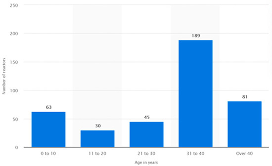
Figure 1.
Number of operating NPPs by average age worldwide as of July 2020 [1].
The LTO of an NPP item is defined as operation beyond the established lifetime set forth by, as an example, license term, design requirements, standards and/or regulations, which must be justified by a safety assessment taking into account the potential ageing mechanisms, as well as their possible causes and consequences. LTO requires thus [2]:
- Diagnosis of the actual state of plant equipment, based on ageing analysis and operating feedback [3].
- Prognosis of the ability of the main systems, structures, and components (SSCs) to continue operation, considering limitations and factors facilitating lifetime extension.
- Ageing management strategy (e.g., actions to detect and control in a timely manner the rate and extent of SSCs physical degradation), including also an exceptional maintenance programme, to ensure that the effects of ageing will not prevent SSCs from being able to accomplish their safety functions.
As indicated in the IAEA SSG-2, 2019 [4], the several degradation mechanisms an equipment may experience in operation are mainly:
- -
- Radiation damage;
- -
- Material fatigue by cyclic loading;
- -
- Corrosion and flow accelerated corrosion;
- -
- Flow accelerated erosion;
- -
- Material ageing under elevated temperatures;
- -
- Material creep under elevated temperatures.
Since many of them occur simultaneously, deterministic analysis must be performed in a conservative manner so as to evaluate any possible synergy between them. Such analysis is particularly important for class 1 components such as the Reactor Pressure Vessel (RPV), which is characterized by a high geometric complexity and by types of alteration and degradation depending on the environment and operation conditions.
This study, based on a deterministic methodology, investigates the thermomechanical behaviour of RPVs during an SBO scenario subjected to both ageing and creep effects simultaneously [5]. To that aim, the RPV was modelled by means of a finite element (FE) code that is extensively used in the nuclear industry to predict the performance of SSCs. Furthermore, this model was qualified based on the FOREVER/C1 experimental activity [6].
It is worthy to note that very few studies concerning the performance of RPV in LTO conditions subjected to (thermal) ageing and creep are available in the open literature, as the attention of researchers, NPP owners, and regulators was focused since the beginning of nuclear era on the issues of RPV embrittlement and irradiation damages.
Most of the researches [6,7,8,9,10,11,12,13,14,15] were carried out on active components and their ageing behaviour is better known than that of large and long-life passive components such as the RPV, piping, concrete structures, and cables. Sharma et al. [7] studied the effect of thermal ageing on low alloy steel (Cr-Mo-V type) at 450 °C, showing embrittlement with ageing, as the impact energy and the hardness reduced monotonically with ageing duration. Yupeng et al. [8] analysed the extent of irradiation damage of the forging in terms of mechanical properties. As the most severe ageing degradation mechanism in RPV materials, irradiation embrittlement is a major issue affecting its integrity through the service life [9,10]. Tipping [9] described some ageing aspects of materials of light water reactor (LWR) components such as irradiation damages, corrosion, and elevated temperature, and proposed suggestions for their mitigation. He highlighted for example that bombardment with neutrons (E > 1 MeV) determines a decrease in fracture toughness and an increase in tensile yield stress and hardness; the extent of such damage depends on irradiation temperature and the impurity level of the steel. Moreover, the study showed that time and temperature combination was promising for the most recovery of the mechanical properties.
Timofeev and Karzov [12,13] studied the effect of thermal ageing on mechanical properties of WWER reactor equipment steels, although the testing conditions (temperature) resulted to differ considerably from plants operation conditions.
Studies become almost rare when the object of the investigation is the simultaneous action of both the long-term thermal ageing and creep [14,15] on RPV performance. In the open literature, even though some studies deal with ageing and/or creep for different nuclear grade components [7,8,9,10,11,12,13,14], very few of them consider the simultaneous effects of ageing and creep [15]. Studies become very rare when the synergic action of these two phenomena is studied for the SBO accident scenario. These challenges make new, innovative, and significant the developed methodological approach (see Section 2) which is “mechanistically based” on an integration between MELCOR 2.2 and Finite Element (FE) codes [16,17,18].
The results provided by MELCOR 2.2 in terms of pressure and temperature serve as boundary conditions for the finite element model. The integration between these codes allowed for the verification of whether the RPV, subjected to a severe accident scenario, is capable of design safety requirements when experiencing thermal ageing and creep.
To be able to determine the impact of ageing on the component’s reliability, first one has to understand the basic ageing mechanisms affecting the component resulting from service conditions, which are the cause of all ageing phenomena. This requires addressing both the effects of physical or chemical degradation of SSCs performance and their obsolescence (i.e., becoming out of date in comparison with current knowledge, technology, codes, and standards).
Equipment degradation may occur at almost imperceptible or rapid rates depending on the service conditions and ageing mainly acting either as single mechanism or in combination (e.g., thermal ageing and creep, complex loading, fatigue, corrosion, irradiation, etc.).
Over time, operational stressors may cause changes in the geometric and material properties of SSCs, which could lead SSCs to fail if not detected and mitigated promptly. Figure 2 shows the trend of safety margin [8,14] of a plant equipment, where the ordinate axis represents the equipment reliability due to ageing effects. In the deterministic analyses performed, they were considered through a variation of time and/or temperature-dependent material properties (e.g., strength, σ (T), or Young′ modulus, E (T), etc. [19,20]).
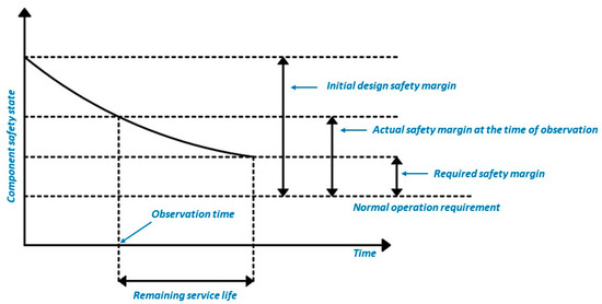
Figure 2.
Trend of the safety margin of NPP equipment versus lifetime. Large safety margin would counter the ageing expected degradation [15].
2. Methodological Approach
Ageing analyses comprise three main phases: scope and screening of SSCs, identification of ageing effects and degradation mechanisms, and definition of ageing management programmes, including analyses performed with a defined design life hypothesis.
Each assessment initiates firstly with the identification of the equipment important to safety to consider in the methodology and then with the definition of degradation mechanisms and phenomena regarding the intended safety functions it performs. Finally, deterministic analyses for the design conditions, including severe accidents (SA) (that could cause RPV failure), are performed for confirming the adequacy of the equipment engineering design, and demonstrating its compliance with established acceptance criteria.
Figure 3 illustrates the logical sequence of the methodology we developed to analyse the effects of ageing on the load bearing capacity of the RPV subjected to SA.
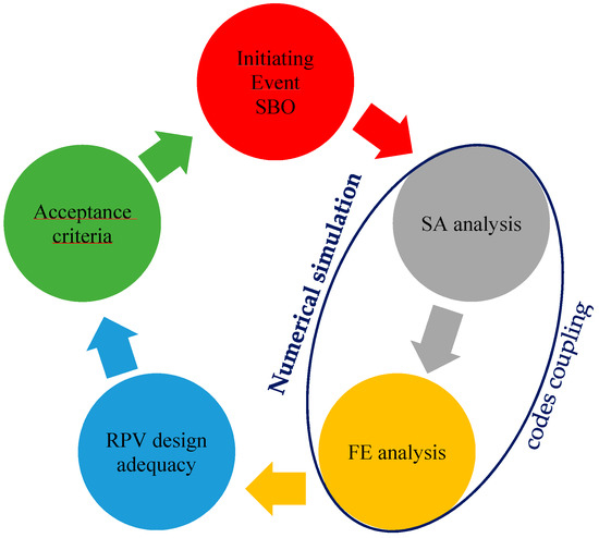
Figure 3.
Phases of the developed methodology for the assessment of ageing effects.
The approach foresees the external coupling between the MELCOR code and MSC©MARC (FE) code used for the assessment of SA scenario and thermo-mechanical performance of RPV, respectively. The external coupling consists of a sequential exchange of data files: the results, in terms of temperature and pressure, calculated in the lower plenum from MELCOR represent the initial and boundary conditions of the subsequent thermo-mechanical FE analyses.
The most important steps are:
- (a)
- Identification of critical SSCs from the standpoint of the plant operation and safety (i.e., RPV in this study);
- (b)
- Definition of materials and environmental conditions;
- (c)
- Identification of the operational loadings, stressors, and essential mechanisms and effects associated with ageing;
- (d)
- Numerical simulation:
- d.1
- For severe accident simulation, points (a) and (b) are implemented in, e.g., MELCOR code 4.
- d.2
- For thermo-mechanical analysis by FE code [18], which allowed for verification of the component structural integrity, points (a), (b), and (c) are implemented;
- d.2.1
- Verification and validation of numerical modelling.
In addition to the point d.2., it is necessary to enter the parameters representative of the causes of deterioration and ageing of the component. Both the material degradation over time and, e.g., the temperature and pressure gradient of the SA transient conditions, need to be set in the FE simulations. The validation of the FE modelling was also carried out based on the FOREVER/C1 experiments [5], which is presented in Section 2.2.1.
In this study, we investigated the performance of aged RPV of the 4500 MWth PWR (reference system of the EU NARSIS project [21]), described in [4], and subjected to severe accident conditions. This is not an easily replaceable component, due to geometric constraints and radiological aspects (neutron irradiation), and the overall plant lifetime depends on how its integrity is maintained and managed. Therefore, RPV integrity must always be guaranteed. Because of the impact that melt relocation and vessel failure may have on subsequent progression and the associated consequences of SA, it is important to accurately predict heat transfer to and from the reactor vessel, as well as the potential for failure, such as local/global failure, and wall penetration of the vessel and structures within it.
2.1. Description of the MELCOR Model
As described in [4], the Reactor Coolant System (RCS) model of a generic high-power Generation III PWR [21] under total Station Black Out (SBO) accident with a core meltdown was implemented by MELCOR 2.2 9541.
Figure 4a shows specifically the nodalisation of the RPV model, the lower head of which is coloured green. Moreover, this model was made of a thermal-hydraulics (CVH) package, core modelling (COR) package, and heat structures package (HS). The core model has nineteen axial levels and six rings, and it was connected with five control volumes, one per ring and additional bypass volume. The RPV has a single down comer, lower plenum, upper plenum and upper head volumes. The lower head was modelled as a quasi-3D structure adjacent to the lower plenum (LP) as shown in Figure 4b: it was divided in 7 segments, each of which with 12 intervals (mesh layers), which are equivalent to 12 + 1 temperature nodes. The LP provides boundary conditions for the lower head wall which is modelled by the COR package only, as it is a solid structure.
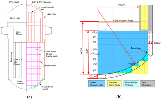
Figure 4.
MELCOR RPV modelling (a), where the lower head model is the hemispherical green-coloured structure. Right (b) presents general MELCOR lower plenum model [17].
Before running the MELCOR transient analysis, steady-state analysis was performed in order to reach the required stable thermo-mechanical conditions in the RPV lower head. Additionally, it was assumed that all the emergency diesel generators and the additional SBO dedicated diesel generators were not available due to combined failure (conservative approach). Passive accumulators were supposed available; active injection systems, low and high-head safety injections, were not available due because of the lack of power. After the depressurization of the Reactor Coolant System, heat removal from the primary side was negligible.
The temperature and pressure trends obtained from the SBO analysis (see Figure 5) were then used as input data for the thermal-mechanical simulations. Analysing these trends, it appears that massive core relocation occurred at 20,000 s, while after 23,000 s, the RPV lower head integrity may not be guaranteed. It is worthy to note that MELCOR analysis stopped at about 23,000 s as reflected in Figure 5. No ex-vessel phase of the accident was considered.
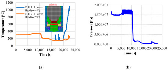
Figure 5.
Plots of temperature (a) and pressure (b) in the lower plenum. In figure (a) the label TLH-ijj refers to the node jj of the segment i, where jj = 13 is the RPV inner surface; i = 1 and i = 7 are the first and last segment of the lower head, respectively, according to the azimuthal angular direction [4].
2.2. Description of the FE Model
The RPV has about 4.4 m internal diameter, about 12 m in height, and has a wall thickness at the core beltline region typically between 0.15–0.25 m [21]. Both the RPV cylindrical part and the lower head spherical portion have 7.5 mm steel liner. The total weight is about 430 tonnes. The 3D FE model reproduces exactly this geometry.
Figure 6 shows the RPV numerical model consisting of about 2400 solid elements, each of which is made of eight-node, isoparametric, and an arbitrary hexahedral element. As this element uses trilinear interpolation functions, the strains tend to be constant throughout the element.
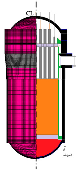
Figure 6.
Vertical cross-section of the RPV model. On the right of the centreline (CL), the main internals are visible: the core region is shown in light orange; the red-coloured region is the lower head (facing the heating-up); the shroud and the control rod system are light green and grey-coloured, respectively. On the left of the CL, the 3D FE discretized model of the RPV is shown.
Preliminary sensitivity analyses investigating the influence of the element type (shell and solid element) and the mesh size (discretization with 720, 2400, and 4800 solid elements) were performed in order to select the best 3D FE-model set-up. For FE-analysis, the following workstation was used: Intel(R) Core(TM) i9-9820X CPU @ 3.30GHz, 3312 MHz, 10 cores. Comparing the obtained results, it emerged that the optimal balance between computational cost and accuracy is obtained for the model mesh with 2400 solid elements. Furthermore, taking advantage of axisymmetry, it was possible to run simulation on a ¼ RPV model guaranteeing at the same time a high level of accuracy and cheaper computational cost.
The RPV’s lower head is loaded by the weight of the molten pool and the vessel, the internal pressure, and the temperature. The primary stresses are the internal pressure and dead weight (gravity), which are not relieved by the deformation of the vessel wall. However, they increased due to the reduction of wall thickness.
The temperature gradient is responsible for secondary stresses, which are relieved by viscoplastic deformation. Particularly, during SA, large thermal stress may arise in the RPV wall thickness, which in combination with the higher internal pressure may induce relevant damages or even more catastrophic failure. Plasticity and creep mechanisms play a significant role in the failure (accumulation of irreversible damage) of the RPV wall. As is widely known, the former is a prompt process occurring only above the yield stress; the latter, characterized by three main phases [22] (primary or transient creep, secondary or steady-state creep, and tertiary creep) is a time-dependent ageing process that can occur either below or above the yield stress and becomes important at elevated temperatures [19].
Typical behaviour is represented qualitatively by the trends in Figure 7. The primary (or transient) creep is characterised by a time-dependent strain rate; the secondary one by a constant strain rate; while the tertiary creep (typically observed at high temperatures and stresses) is characterised by an exponential increase of the strain rate up to the rupture. The creep strain rate () can be formulated as follows:
where:
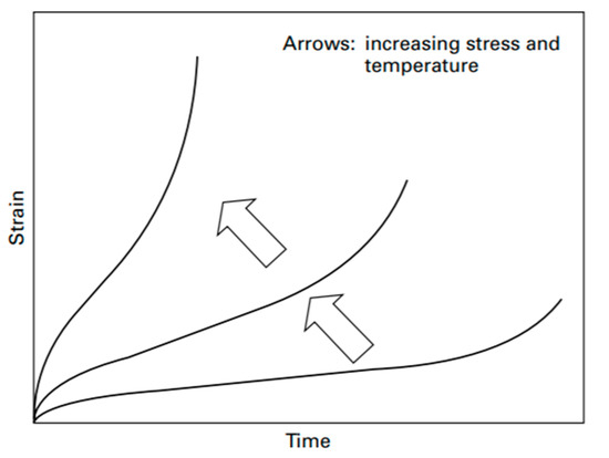
Figure 7.
Schematic creep behaviour varying with stress and temperature [23]. Deformations (elastic plus plastic strain) due to creep are divided into three different regimes.
- σ: stress,
- ε: strain,
- T: temperature,
- t: time.
Although it is generally considered that, for metal, creep often becomes apparent at temperatures higher than 0.4 Tm, where Tm (~1500 °C for SA533B1 21) is the melting temperature, it may appear at various levels of homological temperature [21]. At temperatures below 0.4Tm and after the initial deformation, the strain is virtually independent of time and increases with increasing of stress and temperature. The rupture lifetime reduces as well.
In the performed coupled thermo-mechanical analysis, we assume that elastic deformation, plasticity, and (secondary) creep occur simultaneously and in synergy with the thermal degradation/ageing of the actualised properties of the material.
In the analyses, creep was implemented by a fully implicit viscoplastic Maxwell model to solve the time-dependent gradual accumulation of plastic deformation [18]. The fully implicit formulation allowed for obtaining unconditional stability for any time step size.
Since the thermal ageing (responsible, e.g., for the decrease in strength properties) leads to a decrease in strength, and the initial creep strength depends on the initial strength of the material at the envisaged temperature, we considered in the simulation performed the most unfavourable conditions to be expected. Especially for thermal ageing, we set nonlinear and temperature-dependent material properties, such as Young’s modulus E(T), yield strength σ(T), thermal expansion coefficient α(T), etc.
Figure 8 shows, as an example, the implemented trend of yield stress vs. temperature.
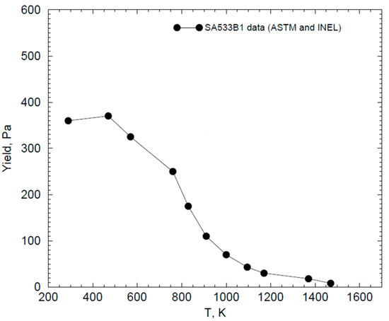
Figure 8.
Yield stress trend as function of the temperature [6]. The strength halves at about 850 K.
RPV material properties of SA533B1 are from the Total Material Database [19]. They were assumed to be isotropic and updated automatically, at each time step, for the entire duration of thermo-mechanical transient analysis. Moreover, those we have considered in the performed FE analyses are the typical ones expected in the last years of the plant operation (usually the last ten years). On the other hand, the effect of neutron damage, such as the irradiation embrittlement, is not considered. It should be emphasized that irradiation embrittlement is not a predictable phenomenon from an FE code; to study the neutrons’ kinetics and the heterogeneous effects caused, specific system codes must be used. The neutron damage was also not assumed due to the high uncertainty that the use of its hypothetical values would have introduced into the analyses.
The boundary conditions set in the simulations are the temperature trend (called TLH-113 in Figure 5a), which was applied at all nodes of the RPV lower head, and the internal pressure (Figure 5b), which was applied over the entire lower plenum surface. Finally, for conservative reasons we assumed the lower head wall in adiabatic condition and no external cooling.
The FE code uses a staggered solution procedure in coupled thermo-mechanical analysis. It first performs a heat transfer analysis, then a stress analysis [18]; changes in temperature distribution contribute to structure deformation through thermal strains and affect material properties. In the numerical simulation, a multifrontal direct solver is used. It is a direct method for solving linear systems and is particularly suitable for sparse matrix systems. It factorizes symmetric and non-symmetric matrices which do not need to be positive definite. The matrix solution is obtained in a two-step approach. The solution is firstly done separately in each domain, and the second step is an iterative solution involving the inter-domain nodes. Due to the second step, this makes the solver performance (and accuracy) dependent on the conditioning of the system [18].
In this study, four case studies which consider in various combinations the effects of ageing, thermal degradation, and creep, are analysed. It should be emphasized that before carrying out the simulation, the validation of the FE model and, in particular, of the creep power law implemented to simulate the RPV behaviour was carried out.
Validation of creep needs is felt as important because the existing methods are based on fits obtained by standard uniaxial creep tests and are not capable of predicting multiaxial creep processes.
2.2.1. Modelling Validation
The FOREVER/C1 experimental campaign [5] was used for modelling verification and validation.
FOREVER/C1 tests were carried out as a part of the Melt Vessel Interaction (MVI) project [5] to study the consequences caused by the molten core with the vessel under SA conditions. The bottom of the RPV, especially, may undergo significant thermal and pressure loads and be liable to fail due to melting or creep rupture.
Multiaxial creep data, obtained from the abovementioned tests, provide thus a rich source of data to validate creep models and minimize uncertainties associated with “imperfect” knowledge of how carbon steel properties degrade at elevated temperatures (E, σ, α, etc.).
The FOREVER test facility employed a small scale (1:10) vessel, made of 15Mo3 steel, representing a RPV with 400 mm diameter, wall thickness of 15 mm, and height of 750 mm (see Figure 9). A high-temperature binary oxide melt (approximately 1300 °C), prepared in a SiC-crucible and placed in a 50-kW induction furnace, is poured into the test section. Furthermore, a MoSi2 50 kW electric heater in the melt pool was allowed to heat and maintain the temperature around 1200 °C.
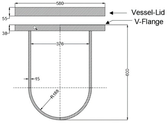
Figure 9.
FOREVER vessel rig geometry (units are in mm) [6].
For the purpose of validation of the creep mathematical model, either a suitable 2D-FE (Figure 10a) or 3D-FE model (Figure 10b) of FOREVER rig was implemented and testing condition simulated. By exploiting the condition of axisymmetry, only one sector of the facility was modelled and meshed. Modelling verification (robustness) is also carried out by comparing the results of the 2D model with those of the 3D model.
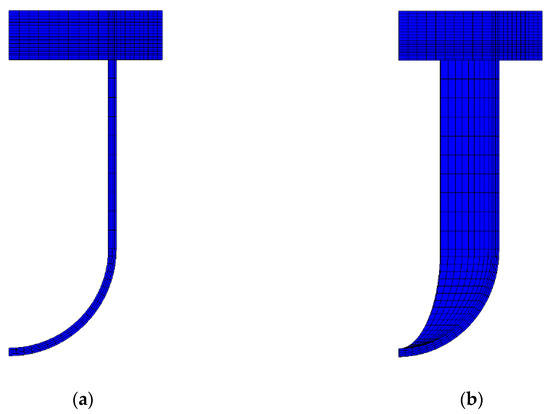
Figure 10.
(a,b): View of a sector of 2D (a) and 3D (b) FE models.
Temperature-dependent material properties were assumed in order to represent the thermal degradation (ageing) suffered by the scaled RPV. Material properties and mechanical and thermal loads are automatically updated at each time step for the entire duration of the experiment simulation. The reduction of material properties are from [5,19].
The creep strain rate () was implemented through a viscoplastic model expressed by the following power law:
where: A = coefficient, ε = equivalent creep strain, σ = equivalent stress, n = stress dependence exponent, T = temperature, m = temperature dependence exponent, t = time, and k = time dependence exponent.
A, n, m, and k were calculated by applying an iterative procedure in which the outcome of each numerical iteration became the starting point of the next one. Iteration continues until the creep strain rate matches that obtained from the FOREVER C/1 data.
Table 1 provides the coefficients of Equation (2) so determined.

Table 1.
Power law coefficients [-].
The FE-model developed (coupling between ageing degradation and viscoplastic model) was able to predict the thermo-mechanical behaviour of scaled RPV in harsh conditions. In what follows we present the results of the simulation of FOREVER/C1 experiments.
Figure 11 shows the comparison between the trends of numerical displacement (obtained from both the 2D and 3D model) and the experimental one at the polar coordinate ϕ0°. They appear almost superimposable, confirming the reliability of the proposed modelling and its capability to simulate/reproduce such a complex thermo-mechanical scenario. Moreover, the maximum displacement at ϕ0° is about 9.4 mm for 2D analysis and 9.3 mm for 3D analysis. Error bars in Figure 11 demonstrate that the discrepancy between numerical and experimental values is less than 3%. R2 = 0.9834 indicates additionally the soundness of the FE modelling.
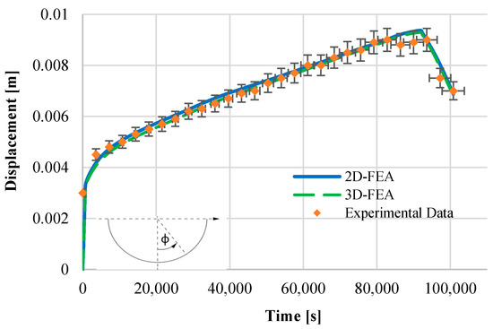
Figure 11.
Experimental vs. numerical displacements at ϕ0°.
Figure 12 shows also the contour plot of the displacement for 2D and 3D FE analysis (“deformation scale factor” of 5.2); the maximum outwards displacement is at the bottom of the lower head of the RPV, in agreement with the experimental test findings presented in [5].
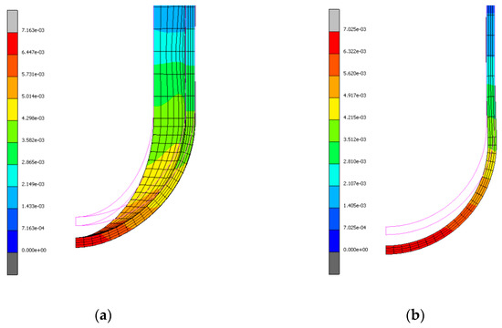
Figure 12.
(a,b): 3D (a) and 2D (b) maximum displacement at the end of transient (28 h).
3. Results and Discussion
The performed simulations focused only on the “in-vessel phase” of the SA and allowed for describing the vessel behaviour up to the failure occurring at the bottom lower head.
During the SBO event, the core melted, relocated, and overheated the bottom of the RPV lower head (see Figure 5a). Prolonged overheating can weaken the lower head of the RPV up to collapse, which may occur in absence of any mitigation action/intervention (i.e., absence of external cooling). Large displacement, which characterizes the collapse, may become even greater as the material properties (already aged) further degrade. Indeed, the very high temperature (>>550 °C) typical of a severe/unprotected SBO event is undoubtedly the main factor that determines a sudden and almost immediate reduction in strength of the material.
Figure 13 show the Von Mises stress, obtained from the numerical analyses, for all four case studies analysed:
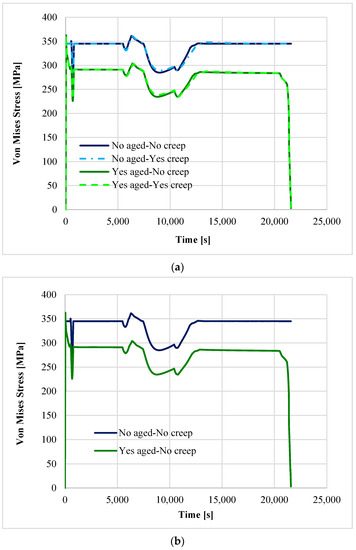
Figure 13.
Comparison of the Von Mises stress trend for all four case studies (a) and only for the aged/not aged RPV (no creep) cases (b) at ϕ0°.
- Unaged RPV, no creep accounted
- Unaged RPV, creep is accounted
- Aged RPV, no creep accounted
- Aged RPV, creep accounted
From the trends it appears that the aged RPV, after about 5.7 h, is about to collapse, regardless of creep, since the limit load at the given temperature is reached. On the contrary, all accidental conditions being equal, structural integrity is guaranteed for non-aged RPV. Analysing Figure 13a, it is not possible to determine what the prevailing ageing mechanism is, i.e., ageing and/or creep, and how each of them are involved in transients’ analysis.
Figure 13b shows clearly that ageing reduces about 25% of the strength capacity of the RPV; its jeopardizing effects become even more relevant as long-term material ageing progresses. Thermal degradation prevails over creep because of the very high temperature reached by the RPV during the SBO. Thermal degradation affects the component more than creep as the transient progresses; RPV is going to fail in few hours without emergency intervention.
The contour plot of the equivalent of Von Mises stress on RPVs is shown in Figure 14a. Aged RPV represents the worst-case scenario characterised also by an earlier loss of structural integrity; in this case, the maximum displacement at ϕ0° is about 260 mm (Figure 14b). Instead, in the case where unaged RPV affected by the creep is considered, the structural integrity is ensured.
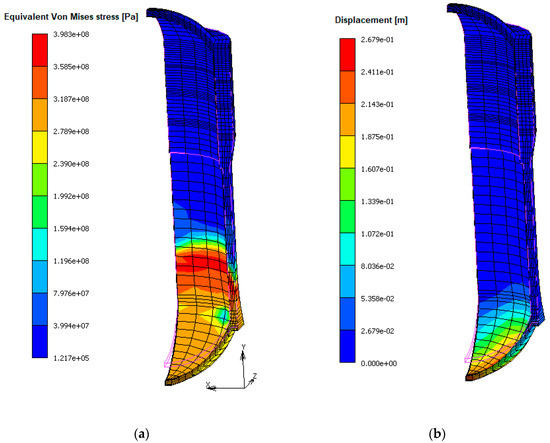
Figure 14.
Qualitative deformed vs. undeformed (magenta edge contour) shape contour plot of Von Mises stress (a) and displacement module (b) at t = 20,570 s for aged RPV affected by creep.
The RPV displacement (Figure 14b) is observed to occur in two stages: the first is characterised by a small and linear displacement rate, and the second is characterised by a large and accelerating displacement rate. The period of linear displacement rate is associated with thermal expansion and elastic displacement as the vessel is heated up and pressurised. The second stage, characterised by a large and accelerating deformation rate due to degradation mechanisms, is due to the increase in temperature.
In an SBO event, the temperature suddenly increases causing marked deterioration of the RPV. The reduction rate of the thermo-mechanical properties as a function of the temperature is responsible for a more marked damage than accumulated damage by creep.
Creep is a slow and continuous plastic deformation of material and requires longer time to compromise the structural integrity.
Since thermal degradation/ageing was the prevalent phenomenon in the SBO scenario, it can be said that it could become a critical aspect to be considered in detail for those NPPs that plan to extend their lifetime. In doing that, a predictive and qualified model to simulate both the normal and accidental operational behaviour of the safety relevant components will play an important role to identify plant weaknesses in advance and threats posed by ageing along with suitable safety management (operation and maintenance) of the plant. This is what the developed methodology proposed in this study demonstrated.
4. Conclusions
This study investigated the influence and impact of ageing and creep phenomena on the behaviour of a 4500 MWth NPP RPV [4]. An SBO event and its main thermo-mechanical consequences were analysed preliminarily by coupling MELCOR and MARC codes: results from former were the inputs of the latter.
The soundness of the FE modelling reproducing complex thermo-structural effects was demonstrated based on the FOREVER/C1 experiments. The comparison between experimental and numerical results highlighted a very good agreement (error of 3% and R2 = 0.9834).
The results carried out from transient simulations of RPV under SBO conditions and an ageing mechanism (thermal degradation and creep acting alone or together) showed:
- The vessel lower head bends downwards under the applied pressure and temperature.
- The aged RPV lower head radially expands about 260 mm.
- When the RPV temperature overcomes about 850 K, the main thermomechanical properties reduce by more than 50%.
- The ageing and long heat-up strongly may compromise severely the RPV integrity in the absence of or delayed emergency intervention.
- An aged RPV system, in end-of-life conditions, may collapse earlier, and in less time, with the same accidental conditions.
- The developed creep constitutive equation can be used to predict vessel deformations under severe accident conditions.
- The FE code is not capable of simulating irradiation embrittlement, which is the reason why it was not considered in the study (to account for such an effect [15,23], a different strategy considering the results of neutron damage in terms of deformed geometry or degraded material properties should be applied).
The performed analyses highlight the importance and impact of time-dependent phenomena on the structural integrity of RPVs.
Considering that most nuclear power plants are designed generally to operate about 40 years (plus life extension period), an accurate knowledge of (not only thermal) ageing performance is accordingly necessary to ensure plant safety operations. For this reason, timely feedback coming from experience and assessment (implementation of effective management programmes) will be essential as well as the use of a valid predictive model such as the one proposed in this study.
In the future, we will also consider performing uncertainty analysis for MELCOR lower head failure, and then we could assess the likelihood of given boundary conditions.
Author Contributions
Conceptualization, R.L.F.; methodology, R.L.F. and P.D.; software, R.L.F., S.A.C., P.D. and S.P.; validation, S.A.C.; formal analysis, S.A.C. and P.D.; investigation, R.L.F., S.A.C. and P.D.; writing—original draft preparation—review, R.L.F., S.A.C., P.D., S.P. and R.C.; editing, S.A.C.; supervision, R.L.F.; funding acquisition, R.L.F. Authorship must be limited to those who have contributed substantially to the work reported. All authors have read and agreed to the published version of the manuscript.
Funding
This research was funded by EURATOM research and training program 2014–2018, grant number No. 755439.
Institutional Review Board Statement
Not applicable.
Informed Consent Statement
Not applicable.
Data Availability Statement
The data presented in this study are available on request from the corresponding author.
Acknowledgments
The paper was carried out in the framework of NARSIS (New Approach to Reactor Safety Improvements) H2020 EU Project (Grant Agreement No. 755439), which has received funding from the EURATOM research and training programme 2014–2018.
Conflicts of Interest
The authors declare no conflict of interest.
References
- Statista. Number of operable nuclear reactors by average age worldwide as of July 2020. In Plant Life Management Models for Long Term Operation of Nuclear Power Plants; IAEA Nuclear Energy Series; No. NP-T-3.18; 2015; Available online: https://www.statista.com/statistics/517060/average-age-of-nuclear-reactors-worldwide/IAEA (accessed on 2 January 2021).
- International Atomic Energy Agency. Assessment and Management of Ageing of Major Nuclear Power Plant Components Important to Safety Primary Piping in PWRs; IAEA-TECDOC-1361; International Atomic Energy Agency: Vienna, Austria, 2003. [Google Scholar]
- International Atomic Energy Agency. Deterministic Safety Analysis for Nuclear Power Plants; SSG-2 (rev.1); IAEA: Vienna, Austria, 2019. [Google Scholar]
- Lo Frano, R.; Darnowski, P. Study of the ageing effects on the lower head failure in a PWR reactor. In Proceedings of the 2020 ICONE Virtual Conference, Online, USA, 4–5 August 2020. [Google Scholar]
- Sehgal, B.R.; Dinh, T.N.; Nourgaliev, R.R.; Bui, V.A.; Green, J.; Kolb, G.; Karbojian, A.; Theerthan, S.A.; Gubaidulline, A.; Helle, M.; et al. Final Report for the Melt-Vessel Interactions’ Project. European Union R and TD Program 4th Framework. MVI Project Final Research Report; Swedish Nuclear Power Inspectorate: Stockholm, Sweden, 1999. [Google Scholar]
- Sehgal, B.R. (Ed.) Nuclear Safety in Light Water Reactors, Severe Accident Phenomenology; Chapter 2–In-Vessel Core Degradation; Academic Press, MIT: Cambridge, MA, USA, 2012; pp. 89–183. ISBN 9780123884466. [Google Scholar]
- Sharma, T. Effect of thermal aging on embrittlement of Cr-Mo-V pressure vessel steel. J. Nucl. Mater. 2019, 527, 151817. [Google Scholar] [CrossRef]
- Yupeng, C. Evaluation of irradiation embrittlement of the weld metals in the Chinese RPV. In Proceedings of the 2020 ICONE Virtual Conference, Online, USA, 4–5 August 2020. [Google Scholar]
- Tipping, P.G. Understanding and Mitigating Ageing in Nuclear Power Plants; Woodhead Publishing Series in Energy Number 4; Woodhead Publishing: Sawston, UK, 2010; ISBN 978-1-84569-511-8. [Google Scholar]
- Kim, H. Swelling resistance of advanced austenitic alloy A709 and its comparison with 316 stainless steel at high damage levels. J. Nucl. Mater. 2019, 527, 151818. [Google Scholar] [CrossRef]
- Tipping, P. Lifetime and ageing management of nuclear power plants: A brief overview of some light water reactor component ageing degradation problems and ways of mitigation. Int. J. Press. Vessel. Pip. 1996, 66, 17–25. [Google Scholar] [CrossRef]
- Timofeev, B.T. Assessment of the first-generation PV state after designed lifetime. Int. J. Press. Vessel. Pip. 2004, 81, 703–712. [Google Scholar] [CrossRef]
- Karzov, G.; Timofeev, B.T. Ageing of RPV and primary circuit piping materials for NPP with WWER during a design operation time. In Proceedings of the International Topical Meeting VVER-2004-experience and perspectives, Prague, Czech Republic, 19–22 October 2004. [Google Scholar]
- Cancemi, S.A.; Lo Frano, R. Preliminary study of the effects of ageing on the long-term performance of NPP pipe. Prog. Nucl. Energy 2021, 131, 103573. [Google Scholar] [CrossRef]
- Cancemi, S.A.; Lo Frano, R. Preliminary analysis of long-term performance of a piping: Aging and creep effects. Materials 2021, 14, 1703. [Google Scholar] [CrossRef] [PubMed]
- Humphries, L.L. MELCOR 2.2 Computer Code Manuals-Vol. 1: Primer and Users’ Guide; Sandia National Laboratories: Albuquerque, NM, USA, 2017. [Google Scholar]
- Humphries, L.L. MELCOR 2.2 Computer Code Manuals-Vol. 2: Reference Manual; Sandia National Laboratories: Albuquerque, NM, USA, 2017. [Google Scholar]
- MSC. Marc Manuals, Vol. A: Theory and User Information; MSC Corp: Vienna, Austria, 2020. [Google Scholar]
- Total Material Database. Available online: https://www.totalmateria.com/ (accessed on 2 January 2021).
- Rempe, J.L.; Knudson, D.L. High temperature thermal and structural material properties for metals used in LWR vessels. In Proceedings of the ICAPP ’08, Anaheim, CA, USA, 8–12 June 2008; p. 8220. [Google Scholar]
- EU H2020 NARSIS Project. Available online: http://www.narsis.eu/ (accessed on 2 January 2021).
- Abe, F. Creep-Resistant Steels; Woodhead Publishing: Cambridge, UK, 2008. [Google Scholar]
- Cancemi, S.A.; Lo Frano, R. Pipe performance in LTO framework: Ageing issues. In Proceedings of the 2021 ICONE Virtual Conference, Online, USA, 4–6 August 2021. [Google Scholar]
Publisher’s Note: MDPI stays neutral with regard to jurisdictional claims in published maps and institutional affiliations. |
© 2021 by the authors. Licensee MDPI, Basel, Switzerland. This article is an open access article distributed under the terms and conditions of the Creative Commons Attribution (CC BY) license (https://creativecommons.org/licenses/by/4.0/).