Article

Analytical Optimal Design of a Two-Phase Axial-Gap Transverse Flux Motor

by
Víctor Ballestín-Bernad
,
Jesús Sergio Artal-Sevil
and
José Antonio Domínguez-Navarro
*
Department of Electrical Engineering, School of Engineering and Architecture, University of Zaragoza, C/María de Luna, 50018 Zaragoza, Spain
*
Author to whom correspondence should be addressed.
Energies 2021, 14(12), 3666; https://doi.org/10.3390/en14123666
Submission received: 3 May 2021 / Revised: 2 June 2021 / Accepted: 15 June 2021 / Published: 20 June 2021

Abstract

:
Transverse flux motors (TFMs) are being investigated to be used in vehicle traction applications due to their high torque density. In this paper, a two-phase axial-gap transverse flux motor is designed for an electric scooter, proposing a novel analytical design method. First, the dimensioning equations of the motor are obtained based on the vehicle requirements, and the stationary dq model is calculated. Then, the motor is optimized using a multiobjective genetic algorithm, and finally a 3D-FEM verification is made. Both the motor structure and the design method aim to have a low complexity, in order to favor the sizing and manufacturing processes through a low computation time and simple core shapes. This approach has not yet been explored in axial-gap TFMs.

1. Introduction

Over the last few decades, different transverse flux motors (TFMs) have been designed and tested in order to explore their potential in vehicle traction applications [1,2,3,4,5,6,7,8,9,10,11].
TFMs have higher torque and power density than radial-flux machines [9,12,13], so they are specially well suited for direct-drive systems such as robotics [14] or in-wheel traction [4,5,8,9,10]. Transverse flux machines have been also analyzed as linear motors [15,16] and direct-drive wind generators [17,18,19,20,21,22] using similar techniques. In both cases, motor or generator, the gearbox is eliminated, resulting in a higher efficiency and reliability. Both features are shared with reluctance machines, so TFMs are strong candidates to inherit reluctance machinery applications such as elevators [23,24], industrial facilities [25], and home appliances [26].
In the field of electric vehicles, some preliminary analysis of TFMs for vehicle traction—not necessarily in-wheel motors—has been made. In [1], a description of the topology is made, together with a 3D-FEM study—the machine geometry is approximated as linear with an extruded mesh—of an outer rotor TFM with I-bridges, also discussing the influence of some parameters and testing a prototype. In [2], a 20 MW, 16-phase TFM is proposed for ship propulsion. Two flux-concentrating machines with U- and C-cores intended for hybrid buses electric propulsion—in this particular case a gearbox is required—are compared in [3], starting from sizing equations proposed in [12]. In [4], the control of TFMs is studied, comparing theoretical and experimental data, and the results show that TFMs are challenging candidates for in-wheel traction of electric vehicles. A simple but too short design method is proposed in [5] for an in-wheel TFM, based on an equivalent circuit and the comparison of 2D- and 3D-FEM simulations. A dual-rotor TFM is proposed in [7,11] as part of the power-split device in hybrid electric vehicles. An optimized design of a scooter in-wheel TFM is proposed in [8] with ferrite magnets similar to Hallbach arrangement and C-cores. In [10], an in-wheel motor with outer and passive rotor is designed and tested.
A comparison of transverse, axial, and radial flux motors for electric vehicles is made in [6], but there is no design process. It is concluded that the TFM shows the highest torque for low electrical load and low speed. However, saturation of the TFM is easier and the torque is lower in the flux-weakening area (high speed). Another comparison is made in [9], in this case between three in-wheel motor topologies (radial flux surface-mounted permanent magnet (PM)-synchronous motor, TFM, and claw-pole machine): the TFM shows a higher torque density but low overload capability, poor power factor, and low efficiency.
Out of the scope of electric vehicles, there are other remarkable publications in the literature about transverse flux machines whose techniques can be equally used to develop a design method for TFMs applied to vehicles. In [12], a set of generic sizing equations is used in a transverse flux machine and its power density results higher than that of an induction machine, especially when rare-earth magnets are used. The torque (reluctance, interaction, and cogging) of a TFM for direct-drive robots is calculated in [14] using 3D flux tubes, and after that a 3D-FEM verification is made. Coupled models (electric and magnetic) have been developed for a linear TFM [15] and the potential of linear TFMs versus longitudinal linear motors has been explored [16].
Transverse flux machines have also been analyzed for wind energy production. In [17], the transverse flux topology is described and a generator is designed analytically with basic equivalent circuits (electric and thermal). In [18], the authors propose a magnetic equivalent circuit (MEC) with 3D flux tubes verified with FEM—computation time is 25 times lower using MEC—. In [19], sizing equations and FEM are used. The MEC proposed in [18] is optimized in [20] using a particle swarm optimization algorithm, with FEM verification again—computation time of MEC optimization is half that FEM optimization—. In [21], a detailed study is made: MEC with 3D flux tubes (analyzing the fringing effect), optimization, FEM, and prototyping. An axial-gap transverse flux generator is designed in [22] using a MEC and a sensitivity analysis.
A generic (with no specific application) FEM-designed TFM is proposed in [27], varying geometric parameters and current. An evolutionary algorithm is introduced in [28] to optimize a TFM with no PMs (reluctance machine in auto-piloted mode), coupling the algorithm with a 3D-FEM model and making prototypes. Sizing equations, MEC, and FEM verification are used in [29], but the proposed transverse flux topology has a sectorial phase arrangement instead of the more common stacking arrangement.
In [30], four prototypes of transverse flux machines are compared in terms of power density and cost: an outer rotor or double stator increase the former, whereas using rectangular PMs and poles decreases the latter. Another comparison is made in [13] together with a review of the topology.
Axial-gap transverse flux machines [4,8,18,20,
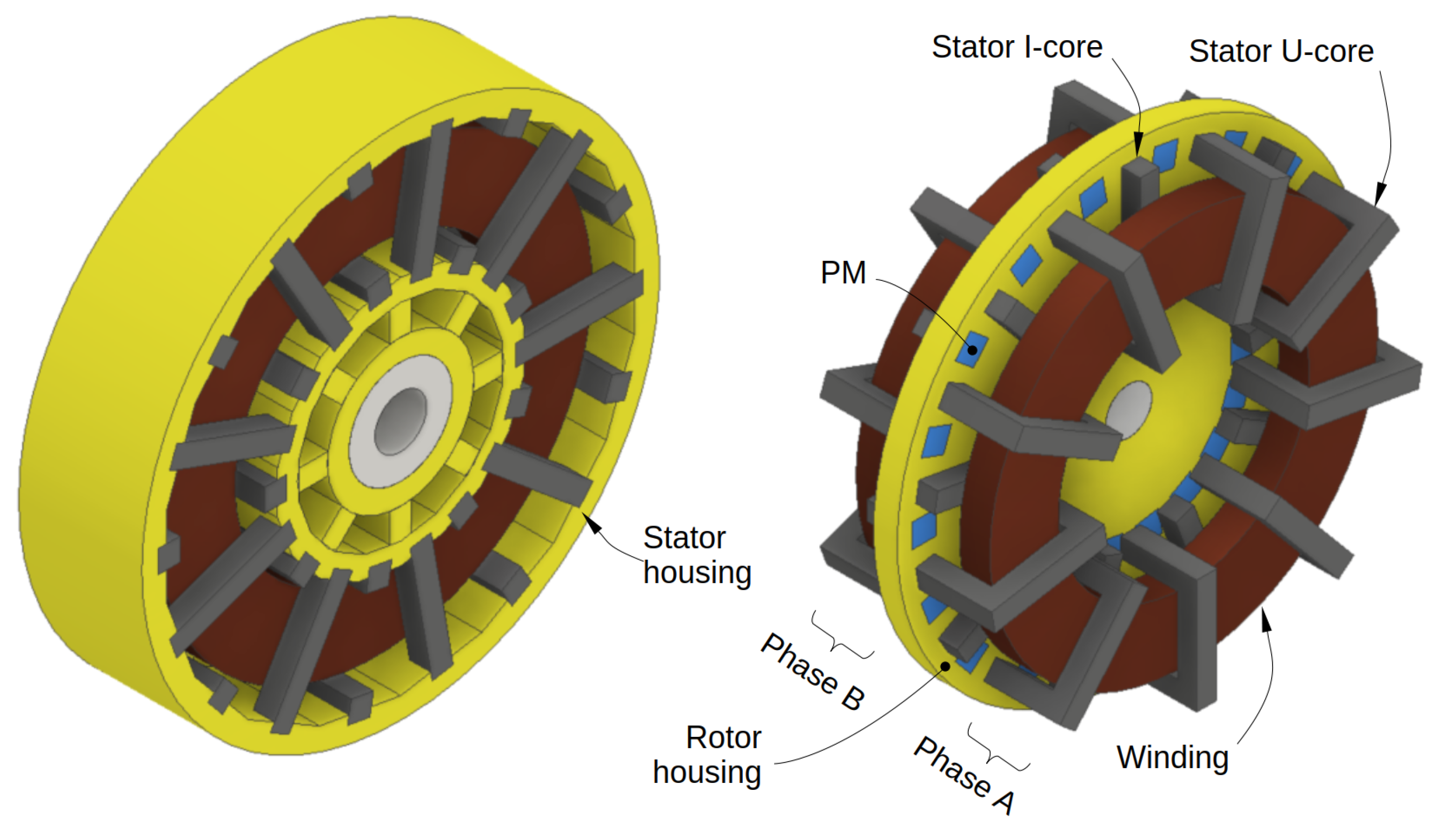
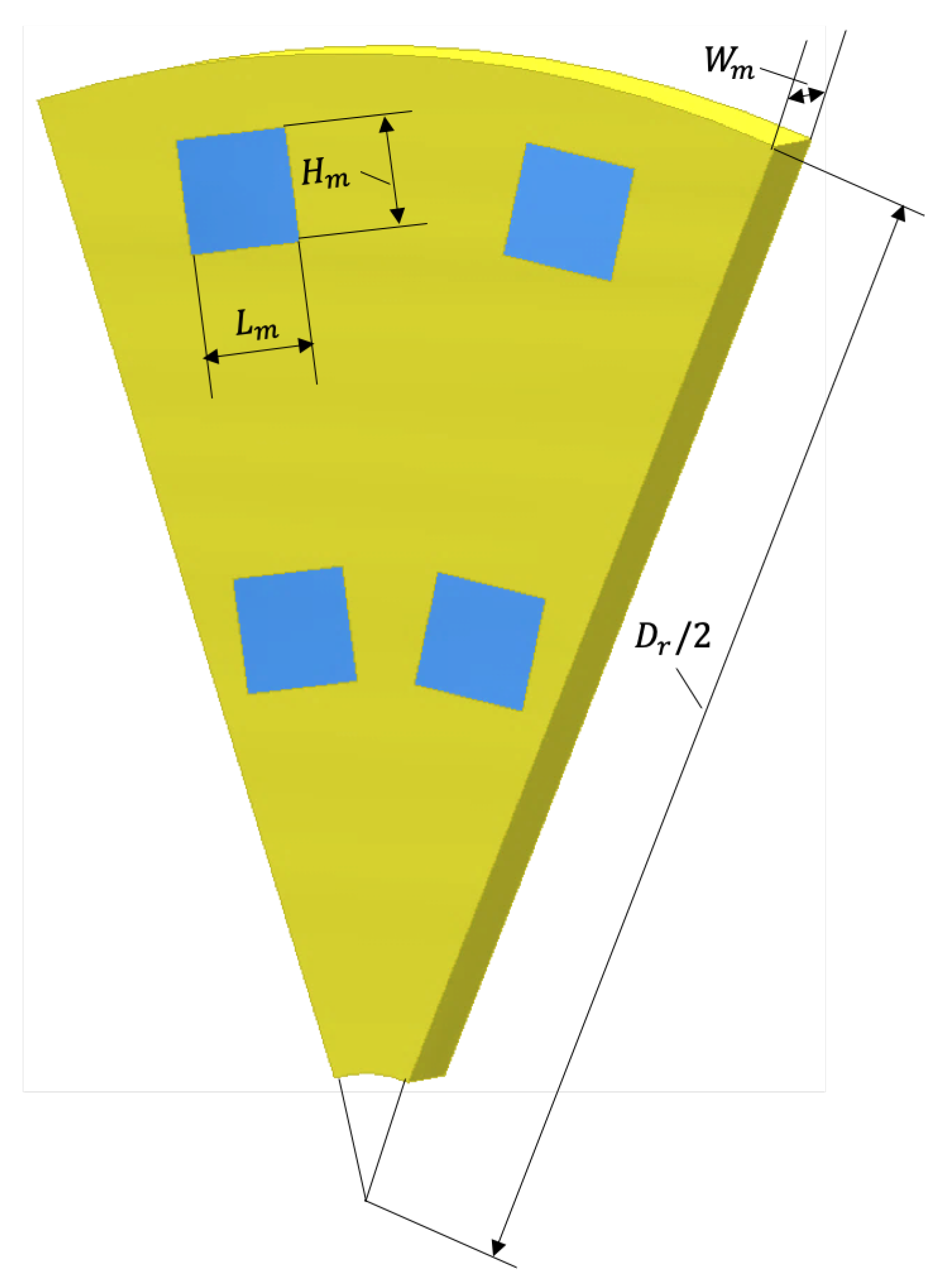
22] have been much less proposed in the literature than radial-gap machines, and the existing topologies are too complex in terms of the magnetic circuit, as well as the manufacturing process. An axial gap favors a reduction in the motor length placing the stator disks opposite each other, thus leading to a two-phase arrangement if a 90 electrical degrees shift between phases is adopted. In this paper, a two-phase axial-gap TFM is designed (Figure 1) to explore its potential for a scooter in-wheel traction. The proposed design aims to have a low cost, so both the machine structure and the design method must avoid the excessive complexity found in literature models. The magnetic circuit is based on U-shaped iron cores, I-bridges, and embedded magnets in a disk-shaped rotor. The geometry of the stator housing is intended for additive manufacturing of a non-magnetic material. Besides, the novel analytical design method combines both dimensioning and performance equations (dq model) in order to avoid the high computational cost of FEM-coupled design methods, then optimizing the analytical model using a multiobjective genetic algorithm, and finally verifying the model using FEM.
This paper is organized as follows. In Section 2, the basic aspects of TFMs structure are explained. In Section 3, the dimensioning equations and the stationary dq model are presented; in Section 4, the previous model is optimized using a multiobjective genetic algorithm; and, finally, in Section 5 a FEM verification is made.

2. TFMs Structure

Electric machines can be categorized according to their operation mode (motor or generator), current periodicity (AC or DC), rotor speed (synchronous or asynchronous), or flux path (radial, axial, or transverse). Table 1 shows different options regarding flux path and three basic features of the machine construction: air gap (radial -RD- or axial -AX-), stator winding (distributed -DT-, concentrated -CO- or ring-shaped -RS-), and rotor (cylindrical -CY- or disk-shaped -DS-). Only transverse flux machines can have either a radial or axial air gap, thus leading to a cylindrical or disk-shaped rotor.
In the transverse flux topology the magnetic flux embraces the ring-shaped coil and the flux path is transverse to the direction of movement, so it is possible to increase the torque by increasing the number of poles but keeping constant the flux linkage. The torque of a generic synchronous motor with the same d- and q-inductances can be expressed as
T m e c = p Ψ m i s , q
It is clear that obtaining a higher torque makes necessary to increase one of the three contributions of the right side of Equation (1):
  • Ψ m can be increased with magnets of higher flux density (i.e., rare-earth magnets that will also probably increase the cost of the motor), a higher area or increasing the number of turns.
  • i s , q can be increased with a higher stator current, but the efficiency will decrease (torque is linear with current, but Joule losses are quadratic) and the current density will increase (thus heating might be too high).
  • p can be increased with a higher number of poles, thus increasing or not the machine diameter.
In radial- or axial-flux machines, the pole section is halved if the pole pairs are doubled, thus Ψ m is halved and the torque remains the same according to Equation (1). Only in TFMs is it possible to increase p keeping constant the flux linkage Ψ m and the diameter, so the torque increases in the same way. Due to TFMs structure—ring-shaped coil and magnetic cores embracing it—the electric and magnetic circuits are decoupled, so the electric and magnetic loads are independent. Otherwise, cogging torque and leakage flux are significant, and also the high number of pieces (cores and magnets) makes the manufacture complex.
Most of TFMs have PMs on the rotor, basically ferrite- or NdFeB-based. Magnets can be surface-mounted (half of the magnets are useless, thus leakage flux can be reduced with I-bridges) or flux-concentrated in an outer or inner rotor, with radial or axial air gap. The stator is based on U- or C-cores of laminated steel or SMC, placed in one or both sides of the stator. The armature winding is generally ring-shaped.
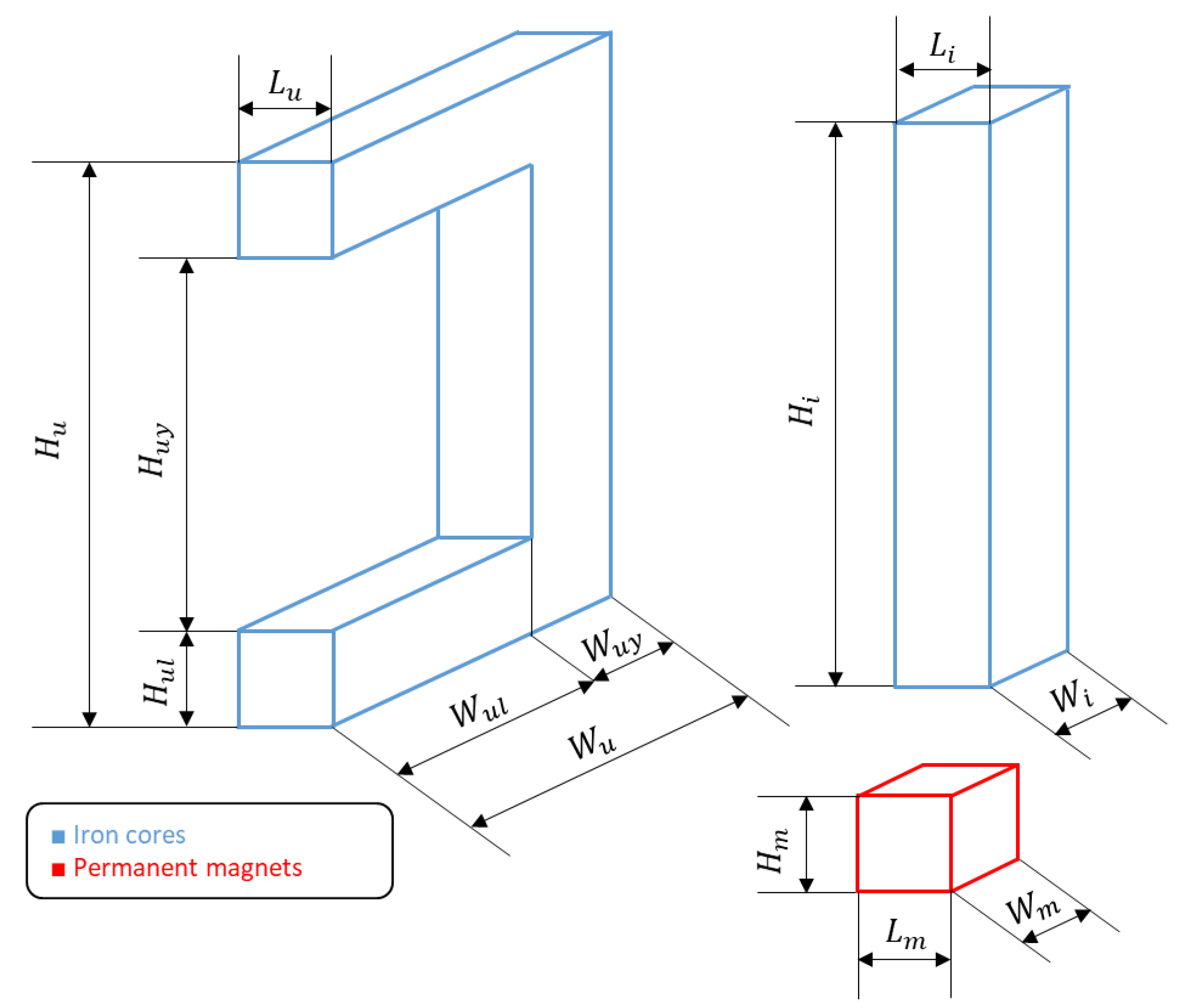
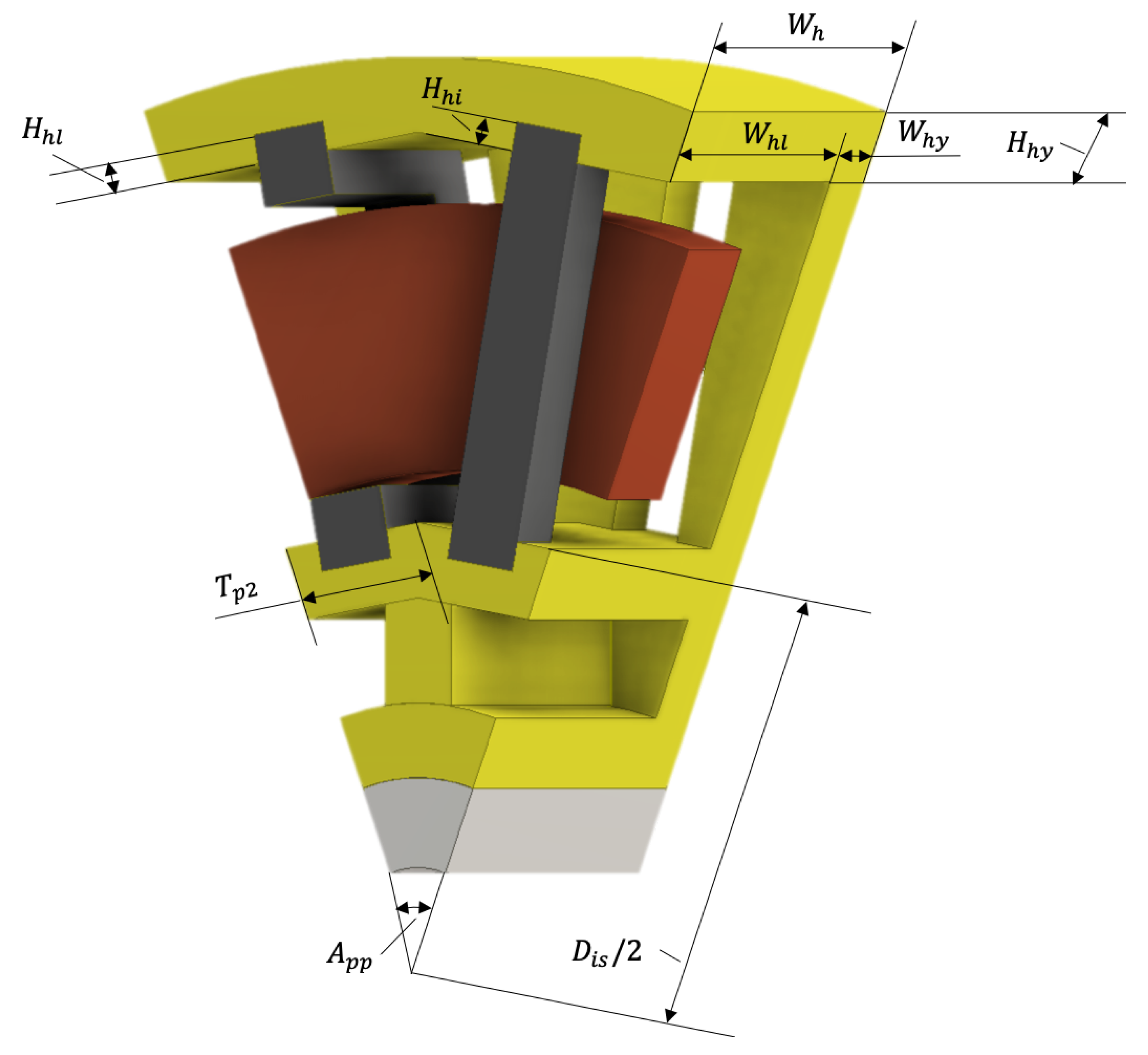
The proposed TFM (Figure 1) has an axial gap, disk-shaped rotor, NdFeB inset magnets, and U- and I-cores of laminated steel. As occurs in many axial-gap machines, it has a larger diameter and lower axial length than an equivalent radial-flux machine.

3. Analytical Design Method

Figure 2 shows the flowchart of the TFM calculation. The main dimensions of iron cores (fixed) and magnets (decision variables) are shown in Table 2 and in Figure 3. Figure 4 and Figure 5 show the stator and rotor housing with their main dimensions. The main requirements of the motorcycle regarding the electric motor are shown in Table 3, these are typical rated values of the electric drive systems of commercial scooters.

3.1. Dimensioning Equations

Regarding the stator housing of the proposed design (Figure 4), several aspects should be noted. First, it is necessary to reduce the active mass of the motor as much as possible in order to increase the torque density. Second, some small gaps are left to introduce the iron cores, thus facilitating gluing for a better fastening. In third place, cooling is considered through different holes in the housing. Finally, some rigs are set for mechanical rigidity. Based on these criteria, the dimensions of the stator housing (Figure 4) can be calculated from the core dimensions.
Core dimensions are also the starting point to calculate a minimum pole pair pitch T p p , m i n —then the pole number will be optimized—. In order to avoid flux leakage between adjacent iron cores, a gap of value 2 L i is left:
T p p , m i n = ( L u + L i ) + 2 L i
Moreover, then the pole pair pitch T p p can be calculated through a factor k T p p that is used as a decision variable:
T p p = k T p p · T p p , m i n
The diameter of the machine and the pole pair angle are calculated in the same way. The coil section and the number of turns are defined though a filling factor from slot dimensions, as usual in the field of electric machinery design.
Finally, the moment of inertia J is necessary to model the mechanic response of the motor:
J = 1 2 M r D r 2 2

3.2. Stationary dq Model

The most typical electromagnetic circuit of TFMs consists of a ring-shaped coil, iron cores (Us and Is) embracing it and PMs on the rotor. The flux path is essentially three-dimensional.
Choosing the wire diameter D w , the stator resistance R s of the ring-shaped coil is defined as
R s = N s ρ c π · mean D c 1 , D c 2 π D w 2 / 4
Moreover, the magnets linkage Ψ m is
Ψ m = N s · B g · mean L m H m , L u H u l
Only self-inductances of the stator are defined (dq axes) because in the proposed design PMs are used on the rotor. Ignoring the cores reluctance and fringing effects, these self-inductances are constant and equal in the dq reference. Their values can be estimated (analytically calculated estimating the flux path), measured through prototypes testing or calculated with FEM. In this paper, the 3D path of the magnetic flux is estimated using flux tubes [14,18,21] in the shape of rectangular prisms, thus avoiding in a first approximation the high computational cost imposed by FEM.
The magnetic circuit of one pole pair—under no-load conditions—in the d-position is shown in Figure 6. The magnetomotive force and the reluctance are calculated using Equations (7) and (8). The remnant flux density of the magnets ( B m ) is 1.1 T—NdFeB magnets are intended to use—and the reluctance is the sum of the air gap ( R m , g ) and PM ( R m , m ) reluctances. The air gap reluctances will change when the rotor moves, as the flux path, but their variations may be negligible compared to the high value of the PM reluctances. In consequence, the machine can be calculated only for the d-position.
F m = B m μ 0 W m
R m , s = 2 R m , g + 2 R m , m = 2 G μ 0 · mean L m H m , L u H u l + 2 W m μ 0 L m H m
Finally, the stator inductance is calculated as follows (Equation (9)), where the term p is due to the transverse flux structure.
L s s = N s 2 R m , s / p
In the proposed design procedure, the dimensioning equations—which finally define the electric parameters—are coupled with the stationary dq model of the TFM:
U s , d = R s I s , d X s s , q I s , q U s , q = R s I s , q + X s s . d I s , d + E 0
Equation (10) can be solved together with torque equation (Equation (11)) and i q control (Equation (12)). In this way, the phasors of current and electromotive force are aligned, so it is possible to obtain a high power factor.
T m e c = p Ψ m I s , q + L s s , d L s s , q I s , d I s , q
I s , d = 0

4. Optimization with Multiobjective Genetic Algorithm

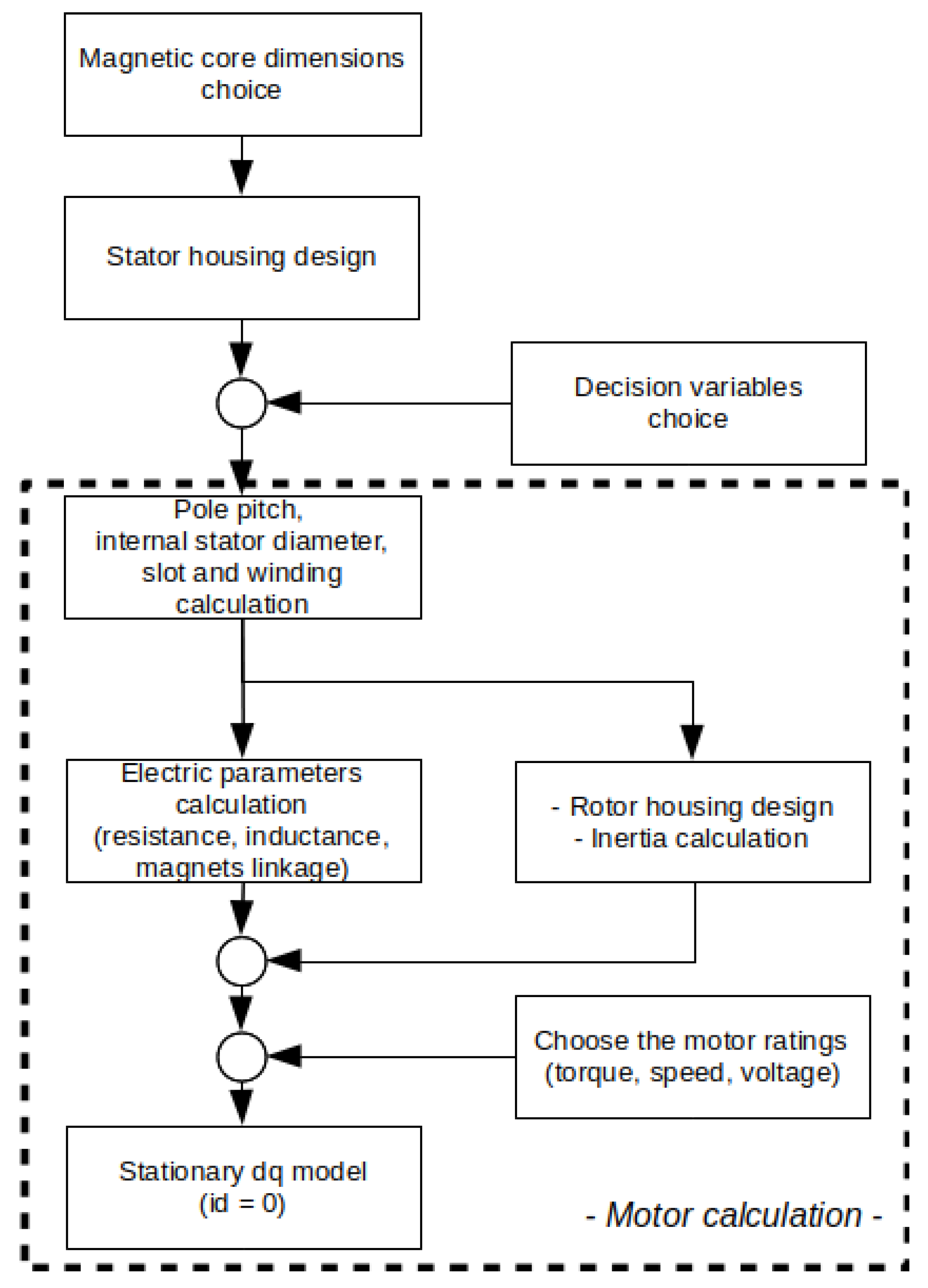
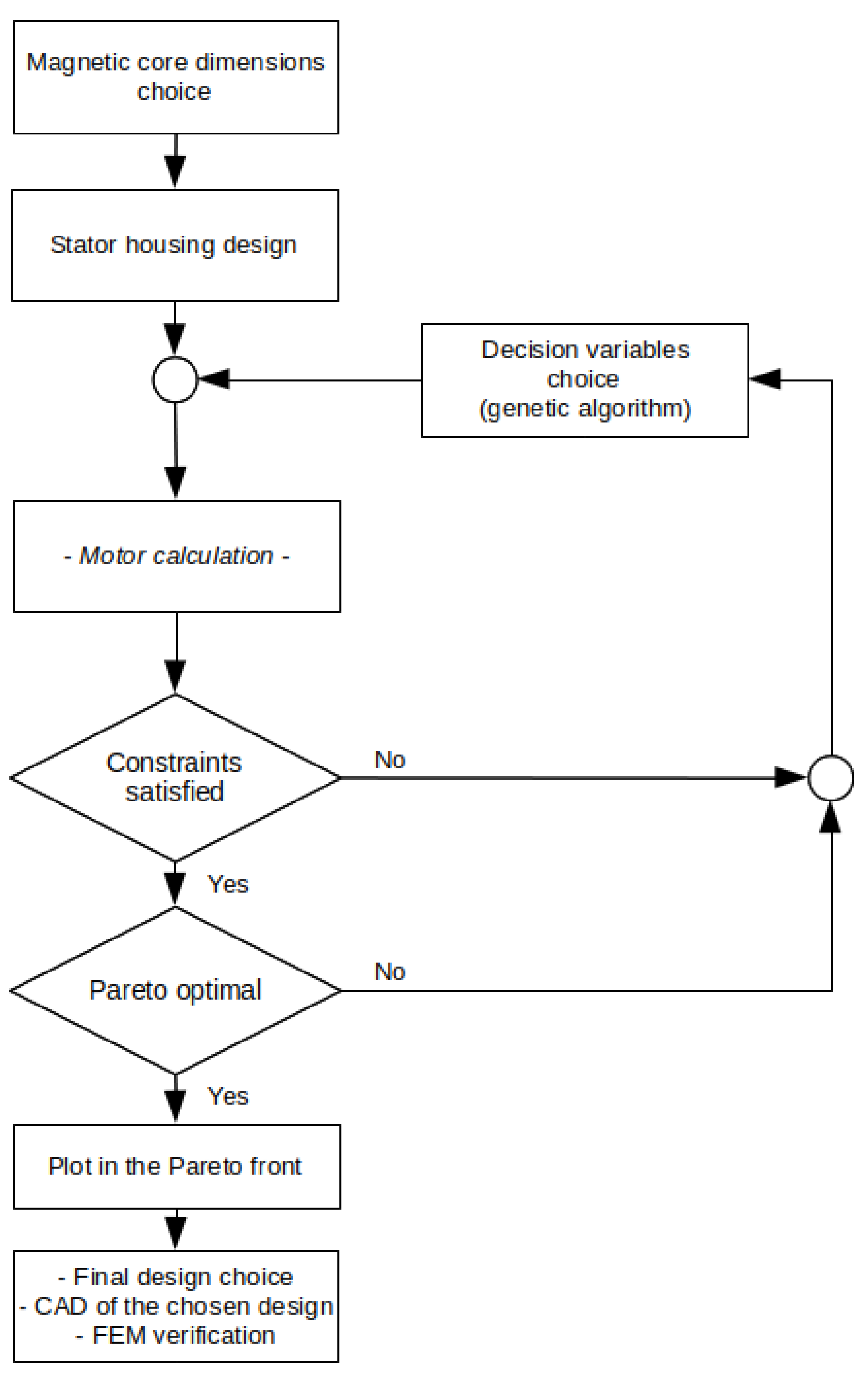
Figure 7 shows the flowchart of the optimization stage. The decision variables of the optimization are shown in Table 4, their ranges are based on previous experience and literature. Furthermore, it is shown if each variable is continuous (C) or discrete (D). The available magnets for the design are shown in Table 5.
The constraints are given by the inverter DC voltage (Equation (13)), current density (Equation (14)), and magnetic saturation (Equation (15)):
U s , d 2 + U s , q 2 < 4 π U s , r a t e d , D C
j r a t e d , R M S < 10 A / mm 2
B g < 1 , 4 T
The objective functions are set to maximize both the torque density and the efficiency (Equation (16)), where the vector x contains the decision variables from Table 4, M is the mass of the motor, and the efficiency η is calculated from the stationary dq model (Equation (10)).
minimize f 1 ( x ) = T m e c M and f 2 ( x ) = η
To check if iron losses ( P i r o n ) were negligible in the efficiency calculation, we made an initial calculation using classical formulas (Equation (17)), where k h = 100 typically in iron, f is the frequency, B g is the air gap flux density, α = 1 , 6 typically in iron, a is the thickness of each iron sheet, σ i r o n is the iron conductivity, and V i r o n is the iron volume of the entire machine.
P i r o n = P h y s t e r e s i s + P F o u c a u l t = ( k h f B g α + π 2 6 f 2 B g 2 a 2 σ i r o n ) V i r o n
With the optimal design values, we obtained 3 W of iron losses, while copper losses were more than 200 W. In this way, it is reasonable to neglect iron losses in the analytical model.
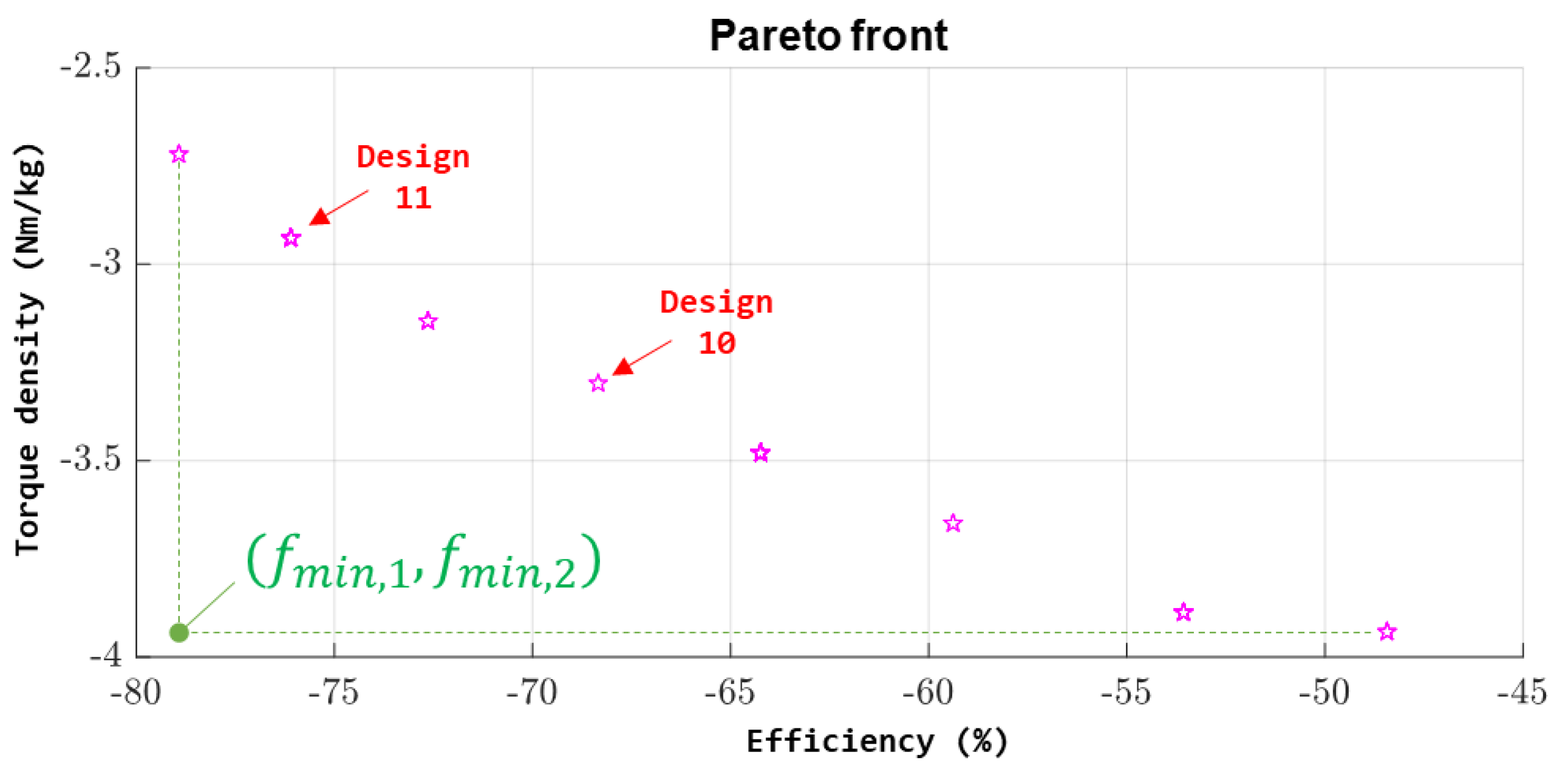
The election of two objective functions allows obtaining a two-dimensional Pareto front (Figure 8), then choosing a unique point as the final design. A MATLAB-based multiobjective genetic algorithm (which is a controlled elitist genetic algorithm, a variant of NSGA-II) has been used. The population size, the number of generations, and the mutation function have been left by default.
The use of a multiobjective genetic algorithm is a novel approach in transverse flux machines design—for example, in [28] a single weighted function is used instead—.
Some results are shown in Table 6: Designs 1–4 correspond to by-hand designs, whereas Designs 10 and 11 are two Pareto optimals. In Designs 1–4, one of the decision variables is modified manually, obtaining different results in terms of efficiency and torque density. Design 10 minimizes the distance to the point f m i n , 1 , f m i n , 2 of the Pareto front, but Design 11 has been chosen instead as the final design because its efficiency is higher than Design 10 and the torque density is acceptable too.
Table 7 shows a comparison between the proposed design and other TFMs, just to check that the obtained torque density and efficiency agree with previous literature of TFMs for in-wheel traction. Moreover, according to Table 4 the pole pairs are limited to 9 (due to material limitations to build a prototype), thus changing the decision limits might raise the efficiency.
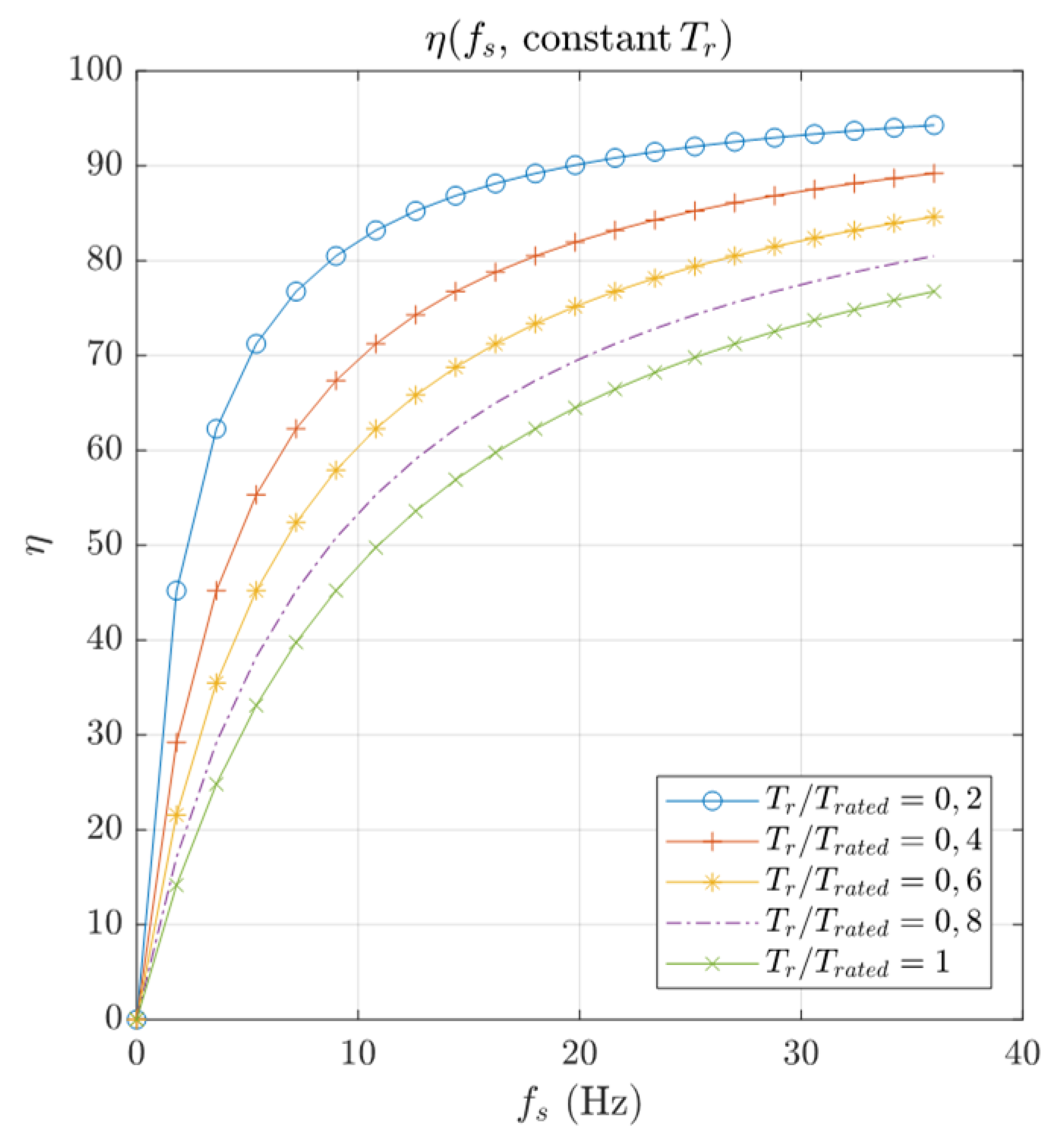
Solving the stationary dq model (Equations (10)–(12)) it is possible to obtain performance curves. For example, the efficiency–frequency curve of the optimum design (Design 11) for different resistant torques is shown in Figure 9: lower efficiencies are obtained at high torque ratios because the current is higher and so the electric losses.

5. FEM Verification

Analytical methods are certainly unable to predict accurately the flux paths, due to the estimation of the magnetic reluctances using flux tubes. In consequence, a FEM model is required to verify the analytical results, especially in axial-gap TFMs, where axial flux couplings may occur. FEM models also allow to obtain results, and therefore improve the motor design and modeling, without the need to build an initial prototype.
Figure 10 shows the meshed model of the proposed TFM (only one pole pair is necessary for the simulation). First-order elements have been used, and later it has been checked that the simulation results are not affected by the choice of first or second-order elements.

5.1. Simulation of the Torque ( i q Control)

Torque has been determined under i q control for different rotor positions and currents, from 0 to rated current (19 A-RMS) and for linear and nonlinear iron. Results of the simulation are depicted in Figure 11 and a comparison between FEM and the analytical method is shown in Table 8.
Analytical and linear FEM results differ significantly due to the difficulty of accurately estimating the inductance in the first method: the inherently three-dimensional flux path makes flux tubes inaccurate, especially in axial-gap transverse flux machines. The flux through the air in the area of the magnets that does not face a U-shaped core produces an axial coupling between the two phases of the machine (Figure 12), resulting in discrepancies which are also very difficult to quantify in order to study separately the contribution of each effect (magnets and cores fringing flux, axial and radial coupling, saturation due to high currents, meshing, etc.). In order to avoid the axial coupling, it could be possible to increase the circumferential gap between the iron cores (increasing thus the pole pitch), but this implies a reduction in the number of poles, thus wasting the main advantage of the transverse flux topology: the magnifying effect of the torque with pole number. In any case, and according to FEM verification, the rapid analytical design method shows accurate enough results taking into account that the calculation takes only a few minutes.
Both linear and nonlinear FEM results show some discrepancy at high currents due to magnetic saturation. According to Figure 11, the torque ripple with no current is 30.39 %, a high value but acceptable in a preliminary study. Specific criteria should be introduced in the design process to reduce the cogging torque and so the torque ripple.

5.2. Simulation of the Flux Linkages ( i q Control)

The plot of the flux linkages (Figure 13), under i q control again, shows that the maximums and minimums of the flux linkage suffer some kind of angular shift when current changes. This effect might be due to the axial coupling between phases (Figure 12). According to Figure 14, the position of the minimums varies quadratically with the rotor angle and this effect does not depend on the material, nor on the magnets shape (square or circular).

5.3. Calculation of the dq Inductances

The stator inductance—calculated analytically with Equation (9)—is 1.3 mH, whereas linear FEM shows 17.5 mH. In both cases, the linear inductances are equal in the dq axes. Discrepancies between analytical and FEM models may lie in the flux path assumed by the former (flux tubes), that is only an estimation, thus a deeper study is required.
The stator reluctance calculated with Equation (8) is formed by four flux tubes and the flux area is close to the magnets area and the U-leg area. Therefore, a similar approach has been adopted with FEM, using the front area of the U-cores to compute the flux ( ψ u ) and then to calculate the inductance (Equation (18)):
L s , u = ψ u ψ m I
The value of the new FEM-inductance L s , u is 3.4 mH, still far from the 17.5 mH obtained with the software in-built tool to calculate the inductance of the winding. An explanation to this difference may be lie in the magnetic flux density: in the circuit model (Figure 6) it is assumed that the reluctance of the cores is zero, but FEM shows that the flux concentration in the U-corners may have a significant effect on the flux linkage, and then on the inductance, due to flux density values higher than B g (Figure 15).

5.4. Simulation of the Back Electromotive Force

The back electromotive force has been calculated under no-load conditions and linear iron (Figure 16). This is an important parameter to evaluate the machine performance eventually as a generator (for example, in regenerative braking). The obtained waveform is similar to a sine but with a flat area near the maximum and minimum values: this is a typical feature of electric machines that have PMs.

6. Conclusions

In this paper, a novel two-phase axial-gap transverse flux motor for in-wheel traction is proposed, using U- and I-cores in the stator and cube-shaped magnets in the rotor. The machine structure aims to combine both the torque magnification inherited of transverse flux machines and a simple design method, in order to avoid the complexity of many designs of the literature in terms of construction and modeling.
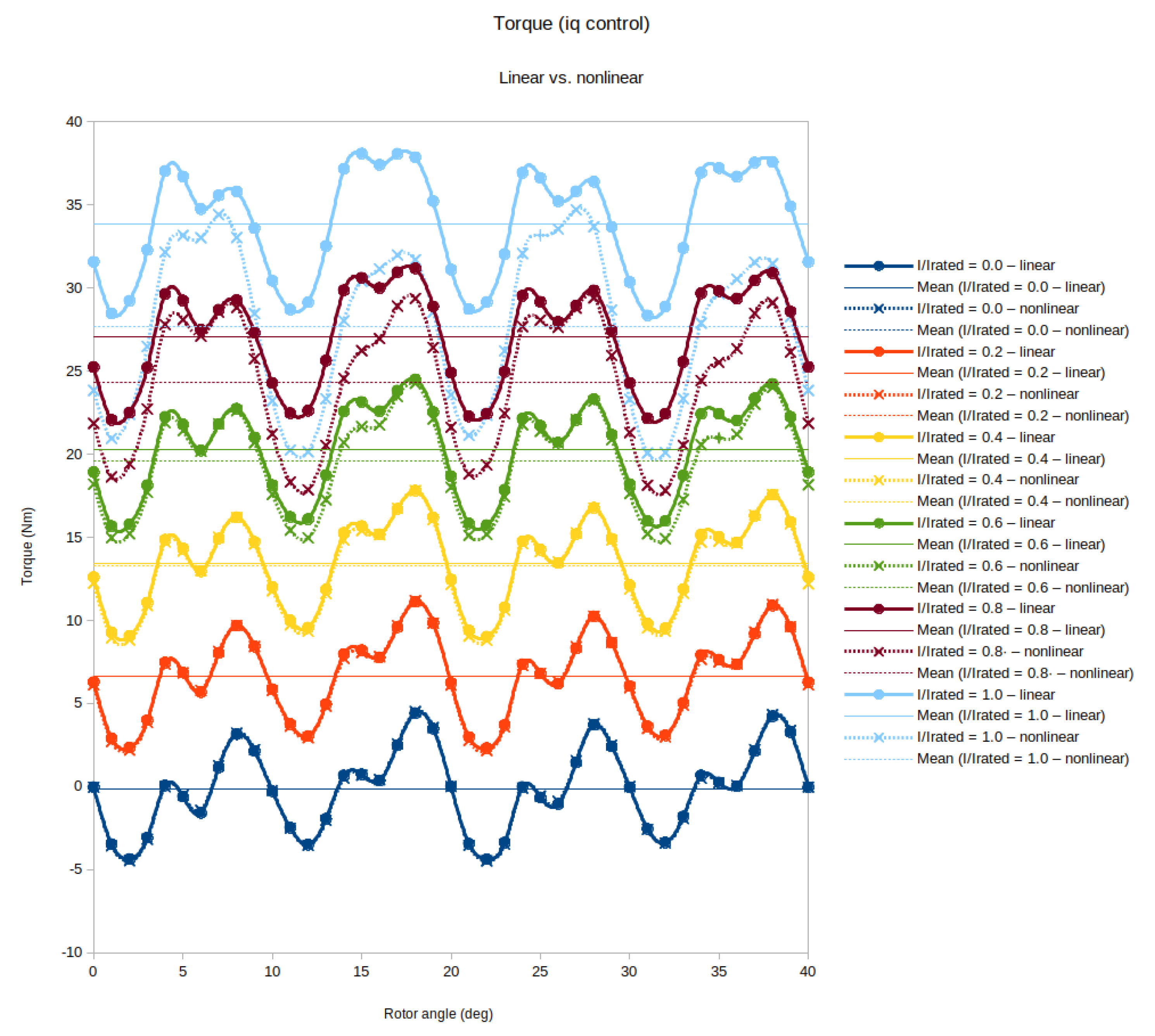
The axial gap favors a two-phase configuration with opposite stator disks that is easier to control than a single-phase motor, providing a constant torque under i q control, as occurs in three-phase machines. The electrical model of the TFM reduces to dq, torque, and control equations, whose parameters depend on machine geometry, leading to a less time-consuming design method than FEM-coupled techniques. In this way, a multiobjective genetic algorithm is used to optimize the dimensions of the machine according to its performance (efficiency and torque density). Finally, a 3D FEM model is computed to verify the analytical model. There are some discrepancies between the analytical and FEM model in terms of torque and inductances, probably due to an inaccurate estimation of the flux path using flux tubes, so this model must be improved. The torque ripple is high, so the design method should be partially reformulated to take into account some specific criteria.

Author Contributions

Conceptualization, J.A.D.-N.; methodology, V.B.-B.; software, V.B.-B.; validation, J.S.A.-S.; formal analysis, V.B.-B.; investigation, V.B.-B.; resources, J.S.A.-S. and J.A.D.-N.; writing—original draft preparation, V.B.-B.; writing—review and editing, J.S.A.-S. and J.A.D.-N.; supervision, J.A.D.-N. and J.S.A.-S. All authors have read and agreed to the published version of the manuscript.

Funding

This research was partially supported by the scholarship “Grants for the recruitment of predoctoral research staff in training—2020–2024 call” from the Government of Aragon (Spain).

Institutional Review Board Statement

Not applicable.

Informed Consent Statement

Not applicable.

Conflicts of Interest

The authors declare no conflict of interest.

References

  1. Henneberger, G.; Bork, M. Development of a new transverse flux motor. IET Digit. Libr. 1997. [Google Scholar] [CrossRef]
  2. Mitcham, A.J. Transverse Flux Motors for Electric Propulsion of Ships. IET Digit. Libr. 1997. [Google Scholar] [CrossRef]
  3. Masmoudi, A.; Elantably, A. An approach to sizing high power density TFPM intended for hybrid bus electric propulsion. Electr. Mach. Power Syst. 2000, 28, 341–354. [Google Scholar] [CrossRef]
  4. Cheng, J.; Tu, X.; Gu, C. Experimental research on new-type of transverse flux permanent magnet machine for electric vehicle. In Proceedings of the 11th International Conference on Electrical Machines and Systems, Wuhan, China, 17–20 October 2008; pp. 3220–3223. [Google Scholar]
  5. Hsu, Y.S.; Tsai, M.C. Development of a novel transverse flux wheel motor. IEEE Trans. Magn. 2011, 47, 3677–3680. [Google Scholar] [CrossRef]
  6. Zhang, B.; Epskamp, T.; Doppelbauer, M.; Gregor, M. A comparison of the transverse, axial and radial flux PM synchronous motors for electric vehicle. In Proceedings of the 2014 IEEE International Electric Vehicle Conference, IEVC 2014, Florence, Italy, 17–19 December 2014. [Google Scholar] [CrossRef]
  7. Zheng, P.; Zhao, Q.; Bai, J.; Yu, B.; Song, Z.; Shang, J. Torque density improvement of transverse-flux dual rotor machine for power-split hybrid electric vehicle application. In Proceedings of the 2014 17th International Conference on Electrical Machines and Systems, ICEMS 2014, Hangzhou, China, 22–25 October 2014; pp. 1178–1182. [Google Scholar] [CrossRef]
  8. Wan, Z.; Ahmed, A.; Husain, I.; Muljadi, E. A novel transverse flux machine for vehicle traction aplications. IEEE Power Energy Soc. Gen. Meet. 2015, 1–5. [Google Scholar] [CrossRef]
  9. Martinez Ocaña, I.; Baker, N.J.; Mecrow, B.C.; Hilton, C.; Brockway, S. Transverse flux machines as an alternative to radial flux machines in an in wheel motor. J. Eng. 2019, 2019, 3624–3628. [Google Scholar] [CrossRef]
  10. Sun, Q.; Zhang, W.; Wang, Q. Fundamental design and analysis of a novel bipolar transverse-flux motor with stator permanent-magnet excitation. Chin. J. Electr. Eng. 2019, 4, 60–66. [Google Scholar] [CrossRef]
  11. Wang, M.; Zheng, P.; Tong, C.; Zhao, Q.; Qiao, G. Research on a Transverse-Flux Brushless Double-Rotor Machine for Hybrid Electric Vehicles. IEEE Trans. Ind. Electron. 2019, 66, 1032–1043. [Google Scholar] [CrossRef]
  12. Huang, S.; Luo, J.; Lipo, T.A. Analysis and evaluation of the transverse flux circumferential current machine. In Proceedings of the Conference Record—IAS Annual Meeting (IEEE Industry Applications Society), New Orleans, LA, USA, 5–9 October 1997; Volume 1, pp. 378–384. [Google Scholar] [CrossRef]
  13. Husain, T.; Hasan, I.; Sozer, Y.; Husain, I.; Muljadi, E. A comprehensive review of permanent magnet transverse flux machines for direct drive applications. In Proceedings of the 2017 IEEE Energy Conversion Congress and Exposition (ECCE), Cincinnati, OH, USA, 1–5 October 2017; pp. 1255–1262. [Google Scholar] [CrossRef]
  14. Babazadeh, A.; Parspour, N.; Hanifi, A. Transverse flux machine for direct drive robots: Modelling and analysis. In Proceedings of the2004 IEEE Conference on Robotics, Automation and Mechatronics, Singapore, 1–3 December 2004; pp. 376–380. [Google Scholar] [CrossRef]
  15. Fu, D.; Gong, J.; Xu, Y.; Gillon, F.; Bracikowski, N. Coupled Circuit and Magnetic Model for a Transverse Flux Permanent Magnet Linear Motor. IEEE Access 2020, 8, 159274–159283. [Google Scholar] [CrossRef]
  16. Zhang, Z.; Tang, X.; Zhang, C.; Li, M. Comparative Study on Modular Longitudinal and Transverse Flux-Switching Permanent Magnet Linear Motor. IEEE Trans. Energy Convers. 2020, 35, 33–42. [Google Scholar] [CrossRef]
  17. Arshad, W.M.; Backstrom, T.; Sadarangani, C. Analytical design and analysis procedure for a transverse flux machine. IEMDC 2001. In Proceedings of the IEEE International Electric Machines and Drives Conference (Cat. No.01EX485), Cambridge, MA, USA, 17–20 June 2001; pp. 115–121. [Google Scholar] [CrossRef]
  18. Hasan, I.; Husain, T.; Uddin, M.W.; Sozer, Y.; Husain, I.; Muljadi, E. Analytical Modeling of a Novel Transverse Flux Machine for Direct Drive Wind Turbine Applications. IEEE Energy Convers. Congr. Expo. 2015, 2161–2168. [Google Scholar] [CrossRef]
  19. Ejlali, A.; Soleimani, J.; Vahedi, A. Review in transverse flux permanent magnet generator design. Iran. J. Electr. Electron. Eng. 2016, 12, 257–269. [Google Scholar] [CrossRef]
  20. Hasan, I.; Husain, T.; Sozer, Y.; Husain, I.; Muljadi, E. Analytical Model-Based Design Optimization of a Transverse Flux Machine. IEEE Energy Convers. Congr. Expo. 2016. [Google Scholar] [CrossRef]
  21. Pourmoosa, A.A.; Mirsalim, M. A Transverse Flux Generator With a Single Row of Permanent Magnets: Analytical Design and Performance Evaluation. IEEE Trans. Ind. Electron. 2019, 66, 152–161. [Google Scholar] [CrossRef]
  22. Noroozi, M.A.; Milimonfared, J.; Yazdanpanah, R. Novel Double-Sided Disk-Shaped Passive-Rotor Transverse-Flux Permanent Magnet Generators for Wind Turbine Applications. In Proceedings of the 2020 11th Power Electronics, Drive Systems, and Technologies Conference, PEDSTC 2020, Tehran, Iran, 4–6 February 2020; pp. 11–14. [Google Scholar] [CrossRef]
  23. Hirayama, T.; Yamashita, S.; Kawabata, S. Design and Analysis of Linear Switched Reluctance Motor with Coreless HTS Excitation Windings for Ropeless Elevator. In Proceedings of the ICEMS 2018—2018 21st International Conference on Electrical Machines and Systems, Jeju, Korea, 7–10 October 2018; pp. 1879–1884. [Google Scholar] [CrossRef]
  24. Li, J.C.; Xin, M.; Fan, Z.N.; Liu, R. Design and Experimental Evaluation of a 12 kW Large Synchronous Reluctance Motor and Control System for Elevator Traction. IEEE Access 2020, 8, 34256–34264. [Google Scholar] [CrossRef]
  25. Liu, C.T.; Li, Y.X.; Yen, S.C.; Hsu, Y.W.; Luo, T.Y.; Shih, P.C.; Lin, S.Y. Structural Optimizations of High-efficiency Direct-on-line Synchronous Reluctance Motors for Metal Industry Applications. IEEE Trans. Ind. Appl. 2021, 9994. [Google Scholar] [CrossRef]
  26. Asok Kumar, A.; Bindu, G.R. Analysis of single phase induction motor and switched reluctance motor with a view of energy conservation. Int. J. Appl. Eng. Res. 2015, 10, 2049–2065. [Google Scholar]
  27. Kastinger, G. Design of a novel transverse flux machine. Proc. ICEM 2002. Available online: http://web.mit.edu/kirtley/kirtley/binlustuff/literature/electric%20machine/Design_of_Tranverse_Flux_Machine.pdf (accessed on 18 June 2021).
  28. Kowol, M.; Łukaniszyn, M.; Latawiec, K.J. Optimization of a Transverse Flux Motor Using an Evolutionary Algorithm; IFAC: Beijing, China, 2009; Volume 14, pp. 71–76. [Google Scholar] [CrossRef]
  29. Bastawade, P.; Chaudhari, B.N.; Ugale, R.T.; Pramanik, A. Analytical and FEA based Analysis of Homopolar Poly-Phase Transverse Flux Machine. In Proceedings of the IEEE International Conference on Power Electronics, Drives and Energy Systems, Trivandrum, India, 14–17 December 2016. [Google Scholar] [CrossRef]
  30. Dobzhanskyi, O.; Gouws, R.; Amiri, E. Comparison analysis of AC PM transverse-flux machines of different designs in terms of power density and cost. In Proceedings of the 58th Annual International Scientific Confererence on Power and Electrical Engineering of Riga Technical University, RTUCON 2017—Proceedings, Riga, Latvia, 12–13 October 2017; pp. 1–6. [Google Scholar] [CrossRef]
Figure 1. 3D model of the proposed transverse flux motor (TFM).
Energies 14 03666 g001
Figure 2. Flowchart of the TFM calculation.
Energies 14 03666 g002
Figure 3. Dimensions of cores (fixed) and magnets (decision variables).
Energies 14 03666 g003
Figure 4. Stator-housing dimensions.
Energies 14 03666 g004
Figure 5. Rotor-housing dimensions.
Energies 14 03666 g005
Figure 6. Magnetic circuit of one pole pair (no-load) in the d-position.
Energies 14 03666 g006
Figure 7. Flowchart of the optimization stage.
Energies 14 03666 g007
Figure 8. Pareto front of the design method.
Energies 14 03666 g008
Figure 9. Efficiency–frequency curve of the Design 11.
Energies 14 03666 g009
Figure 10. Meshed model of one pole pair.
Energies 14 03666 g010
Figure 11. Torque for different positions and currents under i q control.
Energies 14 03666 g011
Figure 12. Axial coupling between phases.
Energies 14 03666 g012
Figure 13. Flux linkages under i q control.
Energies 14 03666 g013
Figure 14. Changes of the position of the minimum flux linkage.
Energies 14 03666 g014
Figure 15. Magnetic flux density in the U-core (linear material), magnets and air.
Energies 14 03666 g015
Figure 16. Back electromotive force.
Energies 14 03666 g016
Table 1. Electric machine types according to flux path.
Radial FluxAxial FluxTransverse Flux
Air gapRDAXRD or AX
Stator windingDT or COCORS
RotorCYDSCY or DS
Table 2. Main dimensions.
H u 60 mm H i 60 mm H h l 4 mm
H u l 10 mm H h i 4 mm
H u y 40 mm W h y 10 mm
L u 10 mm L i 10 mm W h l 48 mm
W u 40 mm W i 10 mm W h l 48 mm
W u l 30 mm W h 58 mm
W u y 10 mm H h y 10 mm
Table 3. Vehicle requirements regarding the electric motor.
Rated torque40 Nm
Maximum speed50 km/h
Base speed25 km/h
Number of phases2
Rated power1000 W
DC voltage48 V
Table 4. Decision variables.
Air gap1–2 mmD
Pole pairs1–9D
Magnet ID1–7D
Fill factor0.50–0.90C
Wire diameter1–2 mmD
Pole pair pitch factor1.00–1.50C
Table 5. Available NdFeB magnets.
Magnet ID B m [ T ] W m [ mm ] L m [ mm ] H m [ mm ]
11.111010
21.12.51010
31.151010
41.1101010
51.12.512.512.5
61.1512.512.5
71.112.512.512.5
Table 6. Designs 1–4 (by-hand) and 10–11 (optimization).
Design ID12341011
Air gap (mm)11.51111
Pole pairs101051099
Magnet ID444377
Fill factor0.850.850.850.850.520.72
Wire diameter (mm)222222
Pole pair pitch factor1.501.501.501.501.011.01
Efficiency (%)666217596976
Torque density (Nm/kg)1.91.93.62.03.32.9
Table 7. Comparison between the proposed design and other TFMs.
TFMPole PairsTorque DensityEfficiency
C-cores and Hallbach magnets [8]153.5 Nm/kg85%
Mutual flux path [9]48-≈63%
64-≈70%
Claw pole [9]48-≈67%
64-≈40%
Proposed TFM92.9 Nm/kg76%
Table 8. Analytical an FEM average torque.
Current (p.u.)Average Torque (Nm)
Analytical, LinearFEM, LinearFEM, Nonlinear
00.00.10.1
0.28.06.86.8
0.416.013.613.5
0.624.020.419.8
0.832.027.224.5
140.034.027.9
Publisher’s Note: MDPI stays neutral with regard to jurisdictional claims in published maps and institutional affiliations.

