Abstract
BIPV (Building Integrated Photovoltaic) system is a building envelope technology that generates energy by converting solar energy into electricity. However, after producing electrical energy, the remaining solar energy is transferred as heat, raising the temperature at the rear of the BIPV module, and reducing electrical efficiency. On the other hand, a PVT (Photovoltaic Thermal) collector is a device that generates electricity from a PV module and at the same time uses the heat transferred to the air layer inside the collector. In general, the performance of air-type PVT collectors is based on energy analysis using the first law of thermodynamics. Since this performance does not take into account the loss amount, it is not the actual amount of power generation and preheat of the collector that can be used. Therefore, an exergy analysis based on the second law of thermodynamics considering the amount of energy loss must be performed. In this paper, an air-type PVT collector to which perforated baffles were applied was tested through outdoor experiments based on ISO 9806 standard. The total energy (thermal and electrical characteristics) and exergy according to the flow rate (100, 150, and 200 m3/h), solar radiation, and rear temperature of the PV module of the air-type PVT collector were analyzed. As a result, the total exergy efficiency of the air-type PVT collector with perforated baffles was 24.8–30.5% when the total energy efficiency was 44.1–63.3%.
1. Introduction
Renewable energy, including solar power and fuel cells, etc., is predicted to provide 62% of the world’s electricity by 2050 [1]. Fuel cells consist of batteries, thermal energy storage (TES), and heat pumps, and a study of Li Sun et al. [2] analyzed this as being a sustainable cogeneration system. Based on the general load schedule, the system was optimized and operated to generate hourly heat and electricity flow patterns, and the overall system efficiency improved to about 3.5% by linking with TES. Moreover, the expansion of the spread of renewable energy has highlighted the need for solar power systems with larger capacities, and Building-Integrated Photovoltaic (BIPV) systems have seen an increase in demand for their efficient use of space. BIPV systems integrate photovoltaics into the building envelope, producing energy by converting solar energy into electricity. The system converts part of the solar energy that reaches PV modules into electrical energy, and a significant amount of solar energy is converted into heat. However, releasing heat produced by PV modules can be challenging as it raises the temperature of BIPV modules, thereby causing a decrease in power generation. Photovoltaic-Thermal (PVT) collectors, which combine PV and solar collector functions, were developed to improve power generating efficiency and use of solar energy by utilizing heat produced by PV modules. In particular, Building-Integrated PVT (BIPVT) systems can simultaneously produce electrical and heat energy for buildings that require heating, and offer higher solar energy use per unit area of installation than conventional BIPV systems.
The base fluids of PVT collectors can be largely divided into air, water, combinations of air and water, and nanofluids. Recent studies have used nanofluids, which offer higher thermal conductivity than those of air and water, to enhance the performance of PVT collectors. Hasan et al. [3] evaluated the performance of PVT collectors with different base nanofluids such as SiC/water, TiO2, SiO2, Al2O3, synthetic oil, and Al2O3/water. A PVT collector with silicon carbide (SiC) nanofluid saw a 62.5% improvement in performance compared to conventional PV modules. Ali et al. [4] performed numerical analysis (MATLAB) to examine the effect of different nanofluids (SiC, CuO, and Al2O3) and base fluids (water, ethylene glycol, and glycerin) on the performance of a PVT collector. The pressure drop of glycerin was the largest and the pressure drop of water was the lowest. In addition, it was analyzed that SiC nanofluids have higher heat transfer rates than other nanofluids.
Among research related to air-type PVT, Choi et al. [5] conducted outdoor experiments on a dual collector capable of simultaneous heating of air and liquid under an air flow rate of 0.0203–0.1262 kg/s (61.52–382.42 m3/h), and assessed the performance of the system in returning collector outlet air as heated air [6].
In recent studies on air-type PVT collectors, the range of electrical efficiency was 9–12%, while that of thermal efficiency was 40–60% [7]. Numerical analysis models were used to improve the electrical and thermal efficiency of collectors, and indoor/outdoor experiments were measured the performance of collectors alone.
Riffat et al. [8] studied parameters affecting the electrical and thermal performance of various PVT systems. The parameters were set as the optimum flow rate circulating inside the PVT collector, the thermal absorber plate, and the thickness of the air layer. The parameter that had the most significant influence on thermal efficiency of PVT systems was the absorber plate.
Park et al. [9] developed a prototype air-type PVT collector suitable for integration in a heat recovery ventilation system, and performed outdoor experiments to assess its performance. The collector had a thermal efficiency of 22% and electrical efficiency of 16% at an air flow of 240 m3/h. Kim et al. [10] developed an air-type PVT collector and conducted experiments under varying air flow rates (100, 150, and 200 m3/h). They reported a difference in inlet/outlet temperature of 8 °C, thermal efficiency of 32.56%, and electrical efficiency of 15.5%. To enhance thermal performance, Kim et al. [11] developed an air-type PVT collector with baffles, and performed outdoor experiments in accordance with ISO 9806. The experimental results showed that thermal efficiency was 26–45% when the average solar radiation of 950 W/m2, ambient temperature of 0 °C, and an inlet flow rate of 60 to 200 m3/h. When the inlet flow rate was 100 m3/h, the collector had a thermal and electrical efficiency of 37.99% and 16.21%, respectively.
Other studies [12,13,14] attempted to improve thermal energy and power generation by developing new air-type PVT collectors with PV module rear fins, curved baffles, and ∇-shaped absorber plates, and assessed their performance. Recently, a study was published that analyzed the efficiency of the collector through numerical analysis by applying a porous metal form to the rear of the module of an air-type PVT collector. Metal form cools the module surface and improves heat transfer from module to form, resulting in an increase in electrical efficiency of about 3% and thermal efficiency up to 85% [15]. Manssouri et al. [16] used air and liquid as collector fluids and designed by applying fins at the bottom of the air layer. In winter, the thermal efficiency increased by 20%, but the electric efficiency decreased by 0.2%.
Boutina et al. [17] designed an air-type PVT collector using a chimney tower effect, and analyzed it by CFD simulations. The results showed that the proposed system improved the heat transfer rate of about 78% compared to existing air-type PVT collectors. Tiwari et al. [18] designed an outdoor dryer that relies on an air-type PVT collector, and reported the average thermal and electrical efficiency, overall thermal efficiency of the air-type PVT collector as 26.68%, 11.26%, and 56.30%, respectively. They found that the air-type PVT collector was at least two times more affordable than electric dryers. Other studies [19,20] reviewed the literature on the effects of systems linking air based PVT and heat pumps or heating equipment. This is for reducing building energy consumption and for thermal comfort and ventilation effect.
Fan et al. [21] designed an air-type PVT-solar air heater (SAH) model using heat pipes, and found the payback time to be between 5.7 and 16.8 years. The thermal efficiency of the model was up to 12% higher, and the PV module temperature was effectively lowered.
As reviewed above, the performance of air-type PVT collectors has been analyzed in various ways through theoretical and experimental research. In recent years, researchers have assessed the performance of PVT collectors based on not only energy efficiency but also exergy efficiency [22,23,24,25,26]. The exergy of a PVT collector is the effective energy that can be utilized as electrical and thermal energy, excluding heat loss from energy entering the collector (incident solar radiation). A PVT collector with higher exergy efficiency produces greater effective energy as output (thermal and electrical). Since materials undergo an irreversible energy conversion process that causes a decrease in energy compared to the initial potential for use, exergy is an important indicator of PVT collector performance. Energy efficiency is calculated by the first law of thermodynamics, and exergy efficiency by equations based on the second law of thermodynamics with consideration of loss due to energy conversion [14,27,28]. Fudholi et al. [14] designed air-type PVT collectors with V-shaped baffles, and examined exergy efficiency through theoretical review and experimental analysis. The exergy efficiency was 13.36% and 12.89% theoretically and experimentally, respectively. Wajs et al. [27] analyzed the exergy efficiency of a PV roof tile, and assessed performance in relation to duct depth and flow rate. The maximum temperature rise was 23.4 °C, and the collector had an overall efficiency of 32%, thermal efficiency of 27%, and exergy efficiency between 5.08% and 9.94%. Numan et al. [29] analyzed the exergy efficiency of an air-type PVT collector in relation to fin density and PV type (polycrystal, and monocrystal) using ANSYS simulations. When fins were installed nearer to one another, the polycrystal and monocrystal PVT collectors saw an increase in exergy efficiency by 70% and 30%, respectively. Their thermal efficiency was analyzed to increase by approximate 55% and 70%.
Agathokleous et al. [30] assessed the exergy and energy of a naturally ventilated BIPVT system through theoretical analysis and experiments. The energy efficiency of the system varied from 26.5 to 33.5%, and the exergy efficiency from 13 to 16%. The PV module of the collector had a maximum temperature of 57 °C, and exergy efficiency increased with outlet temperature.
The range of exergy efficiency in past research [24,25,26,27,28,29,30,31,32,33,34] was between 10 and 38.5%; the various conditions taken into account were air layer height, PV module transmittance, flow, and climate.
In this study, a new air-type PVT collector with perforated baffles was designed, and its energy and exergy performance were evaluated. For this purpose, outdoor experiments were performed under conditions meeting international standards, and the experimental results were used to analyze the electrical/thermal energy efficiency and exergy efficiency considering heat loss.
This paper is divided into two sections. In the first section, the newly designed air-type PVT collector was described, and the experimental method and measurement items for testing the collector were written. The following sections consist of explanations of equations for calculating energy and exergy performance, and were written in sequence with thermal performance analysis, electrical performance analysis, and exergy analysis.
2. Design and Experiment Method
2.1. Design of Air-Type PVT Collector
The air-type PVT collector developed in this study comprised a Glass to Back-sheet (G to B) type PV module, air layer, and insulator, and measured 1013 × 1672 × 32 mm in size (Figure 1). The PV module had 60 monocrystal cells between the front glass and transparent back-sheet, and its specifications are provided in Table 1. Air enters the collector through the inlet at the bottom, and is released through the outlet at the top. The front absorption layer contains perforated thermal absorbers for heat absorption and air flow between the PV module and insulator. Perforated thermal absorbers were in the form of baffles, enhancing heat transfer performance by creating turbulence within the air layer. In this study, the new air-type PVT collector was designed completely different from the PVT collector of the previous studies [11,12] in terms of cost and weight reduction. The PVT collector is composed of G to B PV module, perforated heat absorbing plate, insulation material, rear plate, and side frame. The glass of the G to B PV module was made of low iron tempered glass, and the black EPS (Expanded Poly Styrene) was used for the insulation. The weight of the collector itself was reduced by using 0.3mm aluminum for the perforated heat absorbing plate and 2mm aluminum for the rear plate and the side frame. In general, unlike the method in which the heat absorbing plate is flatly installed under the air layer, the heat absorbing plate applied to the collector of the new design has a perforated/bent shape. This has the advantage of reducing the weight of the collector due to perforation, and less dead space and pressure drop that degrade thermal performance due to the perforated shape occurs, so that the air flow in the collector is uniform.
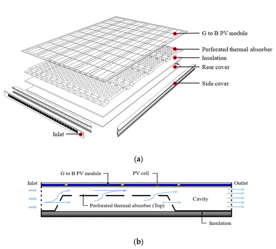
Figure 1.
Concept of the air-type PVT collector with perforated baffle: (a) 3D blown-up picture and (b) cross sectional profile showing air flow direction.

Table 1.
PV module specification.
A previous study [35] conducted CFD modeling analysis on the design of perforated thermal absorbers to assess the performance of air-type PVT collectors. The perforated thermal absorbers with a perforation rate of 34% had a bending angle (a) of 60°, ratio of air layer height to baffle height () of 0.8, and bent upper length of baffle plate () of 280 mm (Figure 2). The air-type PVT collector showed the best performance with a thermal efficiency of 42.5 % (507 Wth) under an outdoor temperature of 5 °C and radiation of 700 W/m2.
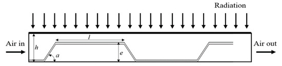
Figure 2.
Concept of perforated thermal absorber (baffle) in the air-type PVT collector.
2.2. Experiment Method of Air-Type PVT Collector
To measure the performance of the air-type PVT collector, outdoor experiments were carried out according to test methods specified in ISO 9806 (Solar energy-Solar thermal collectors-Test methods) [36]. The experimental setup was as shown in Figure 3 and Figure 4, and experiments were carried out on the rooftop of a building in Kongju National University (36.85 N, 127.15 E) in Cheonan. A collector was installed on a two-axis tracker with angles adjustable in the horizontal (0–160°) and vertical (15–90°) directions. The angle was adjusted such that radiation reached the normal to the surface of the collector. The experiments were conducted in April to May 2020 under a radiation intensity of at least 700 W/m2 on the inclined plane and varying inlet/outlet flow rates of 100, 150, and 200 m3/h. For thermal and electrical performance analysis of the air-type PVT collector, variables such as inlet/outlet temperature and flow rate, PV power generation, PV module rear temperature, solar radiation, outside temperature, wind speed were measured (Table 2). Experimental data was collected for ten minutes under normal conditions of inlet/outlet flow, temperature, and outside temperature. Here, normal conditions refer to values falling within the deviation provided in Table 3.
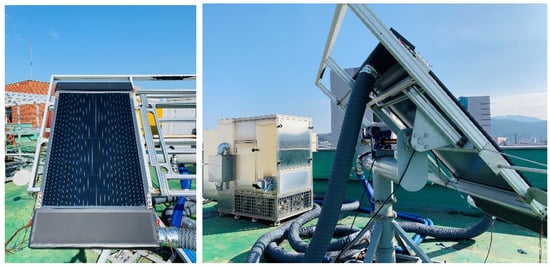
Figure 3.
Installation for air-type PVT collector Experiment.
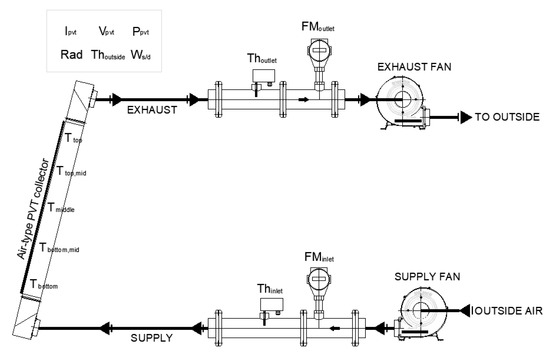
Figure 4.
Scheme for Experiment of air-type PVT collector.
Table 2.
Specifications of the measuring equipment.
Table 3.
Permitted deviation of measured parameters during a measurement period [37].
3. Results and Analysis
3.1. Mathematical Formulations
Thermal and electrical efficiency, used to assess the thermal and electrical performance of the air-type PVT collector was calculated in accordance with ISO 9806 [31] and IEC 61215 [32].
Thermal efficiency of the air-type PVT collector is given by Equations (1) and (2). Electrical efficiency of the air-type PVT collector is given by Equation (3).
where is heat gain (W), is outlet mass flow rate (kg/h), is outlet specific heat of air at a constant pressure (J/kg °C), is outlet air temperature (°C), is inlet mass flow rate (kg/h), is inlet specific heat of air at a constant pressure (J/kg °C), is inlet air temperature (°C), is outdoor specific heat of air at a constant pressure (J/kg °C), is ambient temperature (°C).
where is thermal efficiency (-), is surface area of the collector (m2), G is solar radiation (W/m2).
where is electrical efficiency (-), is maximum current (A), is maximum voltage (V), is maximum power (W).
Researchers have used various mathematical equations to calculate energy entering the PVT collector () and solar radiation exergy () to determine effective thermal and electrical energy produced by PVT collectors. In this study, the exergy equation developed by Wajs et al. [27] was employed for exergy efficiency analysis.
Exergy loss () is obtained by subtracting exergy () produced by the PVT collector from energy entering the collector (). Exergy produced by the PVT collector is obtained by summing the thermal exergy () and electrical exergy (.
Exergy analysis of the PVT collector considering the exergy balance is given by Equations (4) and (5).
The fluid enthalpy of the PVT collector varies with solar heat gain, and thermal exergy is determined by solar heat gain, outside temperature (), and collector outlet temperature ().
Thermal exergy is calculated by Equation (6) [27].
To calculate exergy efficiency, the exergy of solar radiation incident on the surface of the PVT collector is required. The formulate for the exergy of thermal radiation proposed by Petela [38] were applied. (The temperature of the sun () is 5760 K).
Solar radiation exergy () is given by Equation (7).
This study calculated the exergy efficiency of the air-type PVT collector, which is the sum of thermal and electrical exergy efficiency. The exergy efficiency is obtained by dividing the sum of PV power () and thermal energy () over solar radiation exergy ().
The exergy efficiency of the air-PVT collector is calculated by Equation (8).
3.2. Energy Performance of Air-Type PVT Collector
The performance of the air-type PVT collector was assessed based on thermal and electrical efficiency at varying inlet air flow (100, 150, 200 m3/h) and radiation. Thermal performance was analyzed while taking into account how the outlet temperature is influenced by air flow entering the collector and radiation incident on the PV module. Considering the effect of radiation reaching the front of the PV module on the rear temperature, the electrical performance including decrease in electrical efficiency with increasing rear temperature was analyzed.
Figure 5 shows the thermal efficiency by inlet air flow in relation to solar radiation. As radiation increased from 800 W/m2 to 950 W/m2, thermal efficiency at varying air flow rates also increased.
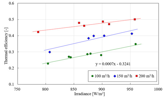
Figure 5.
Effect of the irradiance on the thermal efficiency.
The average thermal efficiency of the PVT collector was 28.1% at an flow rate of 100 m3/h; values were 37.9% at 150 m3/h, and 47% at 200 m3/h. At peak radiation (approximately 950 W/m²), the thermal efficiency was 34.7% at an air flow of 100 m3/h, 41.2% at 150 m3/h, and 49.9% at 200 m3/h. During the experimental period, the average outside temperature, average wind speed, and average radiation were 25 °C, 1.39 m/s, and 716–958 W/m2, respectively.
The temperature rise (difference in inlet and outlet) grew smaller with increasing air flow at the inlet, and temperature increase within the collector was more significant under higher levels of radiation (Figure 6). Flow velocity within the collector increases when air enters through the inlet. The shorter time taken for heat transfer through the back of the PV module and perforated baffles slows down the temperature increase within the collector. The temperature ranged from 10 to 17 °C at an inlet air flow of 100 m3/h, and decreased from 6 to 16% with increasing air flow.
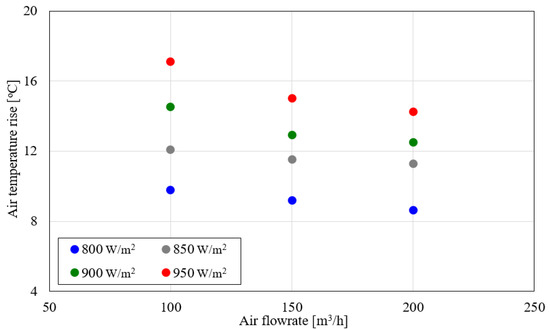
Figure 6.
Effect of the air flowrate on the air temperature rise.
Figure 7 shows the power of the PVT collector and PV module rear temperature in relation to solar radiation. For an outdoor temperature range of 21–31 °C, the output power of the PV module rose 217 Wp to 263 Wp with increasing radiation. The PV module rear temperature fell in the range of 44–52 °C under the ambient conditions. The PV module rear temperature increases slightly and the outlet temperature of PVT collector increases, which shows that it was largely unaffected by the increase in radiation. Therefore, the cooling effect of the PVT collector helps to minimize the decrease in power generation. This becomes faster the air flow because the length between the bent perforated baffle plate applied in the air layer and the PV module is narrow. Heat transfer is promoted by convection from the rear of the module to the air, and there is an effect of raising the collector outlet temperature. Therefore, the collector to which the bent perforated baffle plate is applied does not increase the PV module rear temperature, does not reduce electrical efficiency. The collector increases outlet temperature and thermal efficiency at the same time.
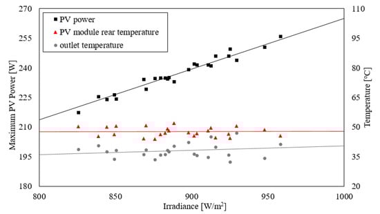
Figure 7.
Effect of PV power and temperature by irradiance.
Figure 8 shows the electrical efficiency of the PVT collector in relation to the PV module rear temperature. The graph indicates a decrease in electrical efficiency with increasing PR module rear temperature. The electrical efficiency dropped from 16.6 to 16.1% when the PV module rear temperature rose from 44 to 52 °C. Under an outside temperature range of 21–31 °C and radiation of 825–958 W/m2, the electrical efficiency decreased by 0.375% for every 1 °C increase in PV module rear temperature.
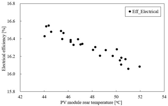
Figure 8.
Electrical efficiency by PV module rear temperature.
3.3. Exergy Performance of Air-Type PVT Collector
The exergy performance of the air-type PVT collector can be assessed based on its thermal exergy efficiency, electrical exergy efficiency, and total exergy efficiency (sum of thermal exergy efficiency and electrical exergy efficiency) at varying inlet air flow rates. Figure 9 gives the exergy efficiency of the proposed collector. Under a radiation of 800–950 W/m2, the thermal exergy efficiency of the air-type PVT collector increased from 8.7% to 14.9% as inlet air flow rose from 100 m3/h to 200 m3/h. At the same time, electrical exergy efficiency increased slightly from 16 to 16.3%. Accordingly, the total exergy efficiency increased by 23.3% from 24.8 to 30.5%. When the flow rate increased from 100 m3/h to 150 m3/h, the increase in the thermal exergy efficiency was small as the electric exergy efficiency increased. On the other hand, when the flow rate increased from 150 m3/h to 200 m3/h, the increase in the thermal exergy efficiency increased while the electric exergy efficiency hardly increased. Therefore, it was confirmed that 150 m3/h is the critical point for the increase in electric exergy efficiency, and the thermal exergy is predicted to increase further at a flow rate of 200 m3/h or more.
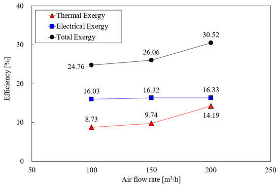
Figure 9.
Exergy and energy efficiency by flow rate.
Figure 10 shows the total energy efficiency and exergy efficiency by air flow. According to the graph, the total energy efficiency and exergy efficiency increase with flow rate. At air flows of 100, 150, and 200 m3/h, the total exergy efficiency values were 24.7%, 26.1%, and 30.5%, while the total energy efficiency values were 44.1%, 54.2%, and 63.3%. With increasing air flow, the total exergy energy is about half of the total energy efficiency. The relatively smaller increase in exergy efficiency can be traced to the heat loss resulting from the difference between outside temperature and outlet temperature of the PVT collector, and the greater heat loss at higher air flow.
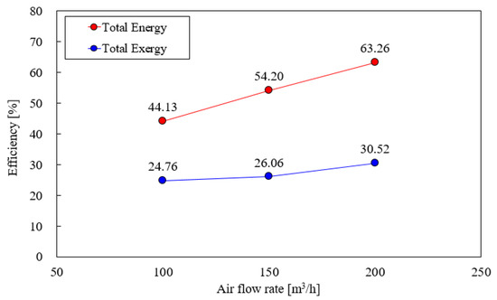
Figure 10.
Compare with energy efficiency and exergy efficiency.
As a result, it can be seen that the air-type PVT collector to which the perforated baffle was applied lost 32.7% of the 63.3% of the energy efficiency of the collector at a flow rate of 200 m3/h and used 30.5% effectively. In addition, it can be seen that the electrical efficiency is higher than the thermal efficiency at 30.5% of the total exergy efficiency.
4. Conclusions
This study developed a new air-type PVT collector with perforated baffles, and conducted outdoor experiments to assess the performance of the proposed system under conditions specified in international standards. The energy (thermal and power generation) and exergy performance of the air-type PVT collector were analyzed in relation to inlet flow, radiation intensity, and PV module rear temperature.
The thermal efficiency of the proposed air-type PVT collector averaged 28.1% at an air flow of 100 m3/h, and 47% at an air flow of 200 m3/h. During peak solar radiation (approximately 950 W/m²) in the range of 100–200 m3/h, the thermal efficiency was between 34.7 and 49.9%. As air flow increased from 100 to 200 m3/h, the difference in inlet and outlet temperatures decreased, falling in the range of 9–17 °C.
In the measurement of electrical and thermal performance of the proposed air-type PVT collector, power generation increased with solar radiation, but there was no significant increase in the temperature at the back of the PV module. This is presumed to be the result of cooling effect by the air flow at the back of the PV module.
The total exergy efficiency of the air-type PVT collector with perforated baffles was 24.8–30.5% when the total energy efficiency was 44.1–63.3%. The total exergy efficiency was about half of the total energy efficiency due to the consideration of loss arising from differences between outside temperature and outlet temperature in thermal exergy, and the consideration of loss arising from differences between outside temperature and solar temperature in solar radiation exergy.
As such, design considerations are required to enhance overall exergy efficiency so as to utilize effective energy through the air-type PVT collector. In addition, the air-type PVT should be designed to operate at high exergy efficiency in building systems.
Author Contributions
Conceptualization J.-H.K.; methodology, J.-H.K. and J.-S.Y.; software, J.-S.Y.; validation, J.-H.K. and J.-S.Y.; formal analysis, J.-S.Y.; investigation, J.-H.K. and J.-T.K.; resources, J.-T.K.; data curation, J.-H.K. and J.-S.Y.; writing—original draft preparation, J.-H.K.; writing—review and editing, J.-T.K.; visualization, J.-H.K.; supervision, J.-T.K.; project administration, J.-H.K.; funding acquisition, J.-T.K. All authors have read and agreed to the published version of the manuscript.
Funding
This work was supported by the Korea Institute of Energy Technology Evaluation and Planning (KETEP) and the Korea energy agency, and the Ministry of Trade, Industry and Energy (MOTIE) of the Republic of Korea (No. 20188550000480) and Basic Science Research Program through the National Research Foundation of Korea (NRF) funded by the Ministry of Education (NRF-2018R1D1A1A09083870).
Institutional Review Board Statement
Not applicable.
Informed Consent Statement
Not applicable.
Data Availability Statement
Not applicable.
Conflicts of Interest
The authors declare no conflict of interest.
References
- BNEF. New Energy Outlook 2019 Executive Summary; BloombergNEF: Sydney, Australia, 2019; pp. 1–8. [Google Scholar]
- Sun, L.; Shen, Y.J.J.; You, F. Sustainable residential micro-cogeneration system based I a fuel cell using dynamic programming-based economic day-ahead scheduling. ACS Sustain. Chem. Eng. 2021, 9, 3258–3266. [Google Scholar] [CrossRef]
- Hasan, H.A.; Sopian, K.; Jaaz, A.H.; Al-Shamani, A.N. Experimental investigation of jet array nanofluids impingement in photovoltaic/thermal collector. Sol. Energy 2017, 144, 321–334. [Google Scholar] [CrossRef]
- Al-Waeli, A.H.A.; Chaichan, M.T.; Kazem, H.A.; Sopian, K.; Safaei, J. Numerical study on the effect of operating nanofluids of photovoltaic thermal system (PV/T) on the convective heat transfer. Case Stud. Therm. Eng. 2018, 12, 405–413. [Google Scholar] [CrossRef]
- Choi, H.W.; Yoon, J.I.; Son, C.H.; Choi, K.H. Performance estimation of hybrid solar air-water heater on single working of heating medium. J. Korean Sol. Energy Soc. 2014, 34, 49–56. [Google Scholar] [CrossRef][Green Version]
- Choi, H.W.; Yoon, J.I.; Son, C.H.; Choi, K.H. Performance evaluation of hybrid solar air-water heater when the heated air is used as inlet air during air and water is heated simultaneously. J. Korean Sol. Energy Soc. 2015, 35, 21–29. [Google Scholar]
- Abuska, M.; Sevik, S. Energy, exergy, economic and environmental (4E) analyses of flat-plate and V-groove solar air collectors based on aluminium and copper. Sol. Energy 2017, 158, 259–277. [Google Scholar] [CrossRef]
- Riffat, S.B.; Cuce, E. A review on hybrid photovoltaic/thermal collectors and systems. Int. J. Low-Carbon Technol. 2011, 6, 212–241. [Google Scholar] [CrossRef]
- Park, S.H.; Bang, A.Y.; Kim, J.H.; Kim, J.T. An experimental study of air type photovoltaic/thermal collector. J. Korean Sol. Energy Soc. 2013, 33, 157–161. [Google Scholar]
- Kim, Y.J.; Lee, K.S.; Kang, E.C.; Lee, E.J. The impact of a PVT air flow rate and panel temperature on thermal and power efficiency. Korean Soc. Mech. Eng. 2017, 33, 85–87. [Google Scholar] [CrossRef]
- Kim, S.M.; Kim, J.H.; Kim, J.T. An experimental study on thermal and electrical performance of an air-type PVT collector. J. Korean Sol. Energy Soc. 2019, 39, 23–32. [Google Scholar] [CrossRef]
- Delisle, V.; Kim, J.T.; Kim, J.H.; Gagne, A.; Ayoub, J. Performance assessment of a new air-based building-integrated photovoltaic thermal solar collector. In Proceedings of the 33rd European Photovoltaic Solar Energy Conference and Exhibition, Ispra, Italy, 25–29 September 2017; pp. 2590–2595. [Google Scholar]
- Franklin, J.C.; Chandrasekar, M. Performance enhancement of a single pass solar photovoltaic thermal system using staves in the trailing portion of the air channel. Renew. Energy 2019, 135, 248–258. [Google Scholar] [CrossRef]
- Fudholi, A.; Zohri, M.; Rukman, N.S.B.; Nazri, N.S.; Mustapha, M.; Yen, C.H.; Mohammad, M.; Sopian, K. Exergy and sustainability index of photovoltiac thermal (PVT) air collector: A theoretical and experimental study. Renew. Sustain. Energy Rev. 2019, 100, 44–51. [Google Scholar] [CrossRef]
- Tahmasbi, M.; Siavashi, M.; Norouzi, A.M.; Doranehgard, M.H. Thermal and electrical efficiencies enhancment of a solar photovoltaic thermal/air system (PVT/air) using metal foams. J. Taiwan Inst. Chem. Eng. 2021. [Google Scholar] [CrossRef]
- Manssouri, O.L.; Hajji, B.; Tina, G.M.; Gagliano, A.; Aneli, S. Electrical and thermal performances of bi-fluid PV/Thermal collectors. Energies 2021, 14, 1633. [Google Scholar] [CrossRef]
- Boutina, L.; Khelifa, A.; Touafek, K.; Lebbi, M.; Baissi, M.T. Improvement of PVT air-cooling by the integration of a chimney tower (CT/PVT). Appl. Therm. Eng. 2018, 129, 1181–1188. [Google Scholar] [CrossRef]
- Tiwari, S.; Agrawal, S.; Tiwari, G.N. PVT air collector integrated greenhouse dryers. Renew. Sustain. Energy Rev. 2018, 90, 142–159. [Google Scholar] [CrossRef]
- Rahman, N.M.A.; Haw, L.C.; Fazlizan, A. A literature review of naturally ventilated public hospital wards in tropical climate countries for thermal comfort and energy saving improvements. Energies 2021, 14, 435. [Google Scholar] [CrossRef]
- Asefi, G.; Habibollahzade, A.; Ma, T.; Houshfar, E.; Wang, R. Thermal management of building integrated photovoltaic/thermal systems: A comprehensive review. Sol. Energy 2021, 216, 188–210. [Google Scholar] [CrossRef]
- Fan, W.; Kokogiannakis, G.; Ma, Z. Optimisation of life cycle performance of a double-pass photovoltaic thermal-solar air heater with heat pipes. Renew. Energy 2019, 138, 90–105. [Google Scholar] [CrossRef]
- Saadon, S.; Gaillard, L.; Menezo, C.; Giroux-Julien, S. Exergy, exergoeconomic analysis of a building integrated semi-transparent photovoltaic/thermal (BISTPV/T) by natural ventilation. Renew. Energy 2020, 150, 981–989. [Google Scholar] [CrossRef]
- Fudholi, A.; Sopian, K. R&D of photovoltaic thermal (PVT) systems: An overview. Int. J. Power Electron. Drive Syst. 2018, 9, 803–810. [Google Scholar]
- Arslan, E.; Aktas, M.; Can, Ö.F. Experimental and numerical investigation of a novel photovoltaic thermal (PV/T) collector with the energy and exergy analysis. J. Clean. Prod. 2020, 276, 1–16. [Google Scholar] [CrossRef]
- Li, G.; Pei, G.; Yang, M.; Ji, J. Experiment investigation on electrical and thermal performances of a semitransparent photovoltaic/thermal system with water cooling. Int. J. Photoenergy 2014, 2014, 1–7. [Google Scholar] [CrossRef]
- Esfandi, S.; Baloochzadeh, S.; Asayesh, M.; Ehyaei, M.A.; Ahmadi, A.; Rabanian, A.A.; Das, B.; Costa, M.V.A.F.; Davarpanah, A. Energy, exergy, economic, and exergoenvironmental analyses of a novel hybrid system to produce electricity, cooling, and syngas. Energies 2020, 13, 6453. [Google Scholar] [CrossRef]
- Wajs, J.; Golabek, A.; Bochniak, G.; Mikielewicz, D. Air-cooled photovoltaic roof tile as an example of the BIPVT system-An experimental study on the energy and exergy performance. Energy 2020, 197, 1–10. [Google Scholar] [CrossRef]
- Sarhaddi, F.; Farahat, S.; Ajam, H.; Behzadmehr, A. Exergetic performance assessment of a solar photovoltaic thermal (PV/T) air collector. Energy Build. 2010, 42, 2184–2199. [Google Scholar] [CrossRef]
- Özakin, A.N.; Kaya, F. Effect on the exergy of the PVT system of fins added to an air-cooled channel: A study on temperature and air velocity with ANSYS Fluent. Sol. Energy 2019, 184, 561–569. [Google Scholar] [CrossRef]
- Agathokleous, R.A.; Kalogirou, S.A.; Karellas, S. Exergy analysis of a naturally ventilated building integrated Photovoltaic/Thermal (BIPV/T) system. Renew. Energy 2018, 128, 541–552. [Google Scholar] [CrossRef]
- Joshi, A.S.; Tiwari, A. Energy and exergy efficiencies of a hybrid photovoltaic-thermal (PV/T) air collector. Renew. Energy 2007, 32, 2223–2241. [Google Scholar] [CrossRef]
- Agrawal, S.; Tiwari, G.N. Overall energy, exergy and carbon credit analysis by different type of hybrid photovoltaic thermal air collectors. Energy Convers. Manag. 2013, 65, 628–636. [Google Scholar] [CrossRef]
- Nazri, N.S.; Fudholi, A.; Mustafa, W.; Yen, C.H.; Mohammand, M.; Ruslan, M.H.; Sopian, K. Exergy and improvement potential of hybrid photovoltaic thermal/thermoelectric (PVT/TE) air collector. Renew. Sustain. Energy Rev. 2019, 111, 132–144. [Google Scholar] [CrossRef]
- Jha, P.; Das, B.; Gupta, R. An experimental study of a photovoltaic thermal air collector (PVTAC): A comparison of a flat and the wavy collector. Appl. Therm. Eng. 2019, 163, 1–13. [Google Scholar] [CrossRef]
- Yu, J.S.; Kim, J.H.; Kim, J.T. A study for improving thermal performance according to variables of perforated baffle in air-type PVT collector. J. Korean Sol. Energy Soc. 2019, 39, 83–91. [Google Scholar] [CrossRef]
- ISO 9806:2017. Solar energy-Solar Thermal Collectors-Test Methods; International Organization for Standard: Geneva, Switzerland, 2017. [Google Scholar]
- IEC 61215:2016. Crystalline Silicon Terrestrial Photovoltaic(PV) Modules-Design Qualification and Type Approval; International Electrotechnical Commission: Geneva, Switzerland, 2016. [Google Scholar]
- Petela, R. Exergy of Heat Radiation. Faculty of Mechanical Engineering Technology; Silesian Technical University: Gliwice, Poland, 1961. [Google Scholar]
Publisher’s Note: MDPI stays neutral with regard to jurisdictional claims in published maps and institutional affiliations. |
© 2021 by the authors. Licensee MDPI, Basel, Switzerland. This article is an open access article distributed under the terms and conditions of the Creative Commons Attribution (CC BY) license (https://creativecommons.org/licenses/by/4.0/).