Abstract
The depth and layout of a horizontal borehole repository has the potential to offer strong isolation of nuclear waste from the surface. However, the isolation may be compromised by the borehole used to access the repository, as it could provide a direct fast-flow path transporting radionuclides from the disposal section to the accessible environment. Thus, backfilling the disposal section and sealing the access hole are considered essential engineered safety components. To analyze the importance of plugging the open space between canisters and sealing the access hole, we numerically calculate non-isothermal fluid flow and radionuclide transport through the borehole and the surrounding geosphere for a variety of scenarios, which include backfill materials with different sealing properties and configurations that potentially induce strong driving forces along both the horizontal and vertical sections of the borehole. The simulations indicate that the dose contribution of radionuclides released through the access hole is small, even if the backfill material is of poor quality or has deteriorated, and even if considerable horizontal and vertical pressure gradients are imposed by assuming the underlying formation is overpressured and that the disposal section is intersected by faults activated during a seismic event. The modeling also reveals that the low influence of backfill integrity on repository performance partly arises from the very high length-to-diameter ratio of the borehole, which favors the radial diffusion of radionuclides—as well as pressure dissipation and associated advective transport—into the surrounding formation rather than axial transport along the borehole. The integrated modeling approach also exposes the importance of accounting for the connections and feedback mechanisms among the various subcomponents of the repository system.
1. Introduction
1.1. Deep Horizontal Borehole Repository
We investigate the disposal of nuclear waste in a deep horizontal borehole repository (DHBR) as a viable option to protect the public from radiation hazards [1]. Such a geological repository consists of an array of vertical boreholes, each with a horizontal section that is drilled into a suitable host formation, and where waste canisters are emplaced end-to-end in the cased horizontal disposal section. To facilitate waste emplacement (and potential retrieval), the disposal section is accessed by a vertical hole, which gradually turns horizontal to reach the host rock at the target depth of approximately 1 to 3 km. The diameter of the borehole narrows with depth in stages, as do the diameters of the casing strings, which are cemented in place. During or after waste emplacement, the space between the canisters and the casing as well as between individual canisters can be filled either with a buffer, which is defined as a backfill that fulfills one or several specific barrier functions, or with a material with no functional safety requirements, or it may be left open. Similarly, as part of repository closure, the vertical and curved sections of the access hole may be sealed and plugged in certain locations, and the rest can be backfilled, with the goal to prevent the development of preferential flow paths and to maintain or restore the natural conditions in the host rock, which may have been disturbed during the operational phase.
1.2. Sealing Requirements for Different Repository Types
The design requirements for the backfill and closure structures for geologic disposal facilities not only depend on the site-specific hydrogeological, geomechanical, and geochemical environment, but also on the overall repository concept and layout. Thus, these requirements are expected to be different for waste disposal in mined repositories, deep vertical boreholes, and deep horizontal borehole repositories.
Mined repositories are large underground structures, which include access ramps, utility shafts, ventilation ducts, underground facilities, caverns, deposition tunnels, or vertical or horizontal deposition holes. As a consequence, the host formation is considerably perturbed during the construction and operating phases, substantially changing the rock stress, fluid pressure, temperature, and geochemical environment in order to allow personnel and heavy machinery to work underground. The relatively shallow depth of a mined repository and the large diameter of the access structures place high demands on the integrity of the engineered barrier system (EBS). Finally, the layout of the repository results in an interconnected network of conduits. If a perturbance occurs at any location and the openings are not effectively sealed, complex gradients and flow patterns may be induced that propagate throughout the repository. As a result, an elaborate system of buffers, seals, plugs, and backfills must be installed (as illustrated, e.g., in [2]) to safely and securely close a mined repository. Considerable efforts have been made to design and physically test the emplacement procedure and sealing performance of backfills and plugs needed to close the large openings of a mined repository [2,3,4,5,6,7].
In the deep vertical borehole disposal concept, the upper section of the borehole is envisioned to be sealed by a series of compacted bentonite and cement seals. Between these seals, the borehole is backfilled with a mixture of cement, crushed rock, or other suitable materials. In addition, bridge plugs and compacted bentonite or cement plugs will need to be installed between the waste strings to support the load of the stack of overlying canisters and to reduce fluid flow [8,9]. As an alternative, backfilling the canisters with a high-strength support matrix could also prevent buckling and load damage [10]. Note that according to [11], seals only need to be effective during the thermal period, after which density stratification of the brine is re-established, and no significant upward driving forces are expected to be present. However, the complexity and heterogeneity of the deep subsurface may call for a longer-term reliance on borehole seals [12].
The sealing requirements for the horizontal borehole concept differ from those needed for mined or vertical borehole repositories. Waste disposal in deep, small-diameter boreholes leads to a small ratio of the cross-sectional area of the access structure to its length. Disturbances of the host rock are minimal compared with those of a ventilated mined repository, and the greater disposal depth increases the barrier effect of the geosphere, which reduces the demands placed on the performance of the EBS, including that of the buffers, seals, and backfill. Furthermore, the disposal section is spatially separated from the vertical access borehole by at least the radius of curvature of the bent section of the borehole—typically a few hundred meters. Moreover, gradients that potentially induce fluid flow and radionuclide transport along the disposal section are perpendicular to those needed for upward migration along the access hole. Conversely, naturally occurring or repository-induced upwards driving forces, such as buoyancy effects caused by heating, are not aligned with the horizontal orientation of the disposal section of the borehole. Finally, horizontally emplaced waste canisters do not accumulate any stacking forces, i.e., no bridge plugs are required.
1.3. Sealing of Waste Deposition and Access Structures
Buffers, seals, plugs, bulkheads, and backfills each are designed to fulfill specific safety requirements, in concert with other components of the EBS. As discussed above, it is important to recognize that these safety requirements differ for different disposal concepts, specifically the depth of the repository, which affects the relative importance of the EBS and geosphere [13]. For mined repositories in particular, dense smectite-rich bentonite, a potential buffer material that is in direct contact with the waste canister, has been identified by most radioactive waste management organizations as an important EBS component (for a review, see [14,15]). Its physical and chemical properties meet a number of requirements needed to assume specific safety functions [16]. For example, the bentonite’s very low permeability prevents the flow of water both to and from the disposal canister, thus protecting the canister itself and limiting advective transport of radionuclides; its swelling pressure establishes good contact between the buffer and the host rock and canister; its ion-exchange and surface-complexation capacities provide sites for radionuclide adsorption; its small pore sizes suppress microbial activity and reduce colloid migration; and its plasticity protects the canister from localized mechanical loads and shear stresses. To fulfill these safety functions, specific requirements are formulated regarding bentonite properties (e.g., maximum permeability, minimum dry density, minimum and maximum swelling pressure) and the environment (e.g., minimum and maximum temperature, maximum salinity, suitable water geochemistry).
The main safety function of deposition tunnel backfill and abutments is to counteract buffer expansion during hydration [17,18]; i.e., their key role is to enable the buffer to reach its intended long-term properties. Similarly, some sections of a vertical access hole are filled with ballast materials whose sole purpose is to increase the effectiveness of a bentonite or cement plug.
Plugs and seals along the access structures are designed to limit flow and advective radionuclide transport. The requirements for some of the seals are complex: they have to reduce liquid flow to limit advective transport, while at the same time be sufficiently permeable for gas to escape, preventing the development of high overpressures in the repository due to gas generation by corrosion and other degradation processes [19]. Some plugs are built to obstruct the inadvertent or malicious human intrusion into the disposal section [2].
Numerous materials and methods to backfill, seal, and plug access structures of nuclear waste repositories have been proposed. As mentioned above, compacted bentonite is the preferred buffer material for most mined repositories located in the saturated zone. However, the installation of dry, expandable bentonite in the disposal section of a horizontal borehole is challenging, although not impossible; several designs of clay-based borehole plugs have been proposed [20,21], whereby, in the basic concept, compacted clay blocks are placed in perforated copper tubes and lowered into the borehole. Upon contact with formation water, the clay expands and protrudes through the perforation, forming a seal, supported by bounding silica concrete plugs. As supplements or alternatives, pumpable components that eventually set, gel, solidify, or swell can be considered as backfill materials between waste canisters and the casing. Such backfills include cementitious slurries [20,22,23,24,25], oil-based fillers (tar, bitumen or asphalt), crosslinked polymers, pumpable grout mixtures, salt, or molten, lead-based pellets that encapsulate the canisters after re-solidification [26,27]. The combination of and interaction between clay-based and cementitious backfill materials has been given special attention for the sealing of both mined and borehole repositories [15,28,29,30].
The deep casing can be removed after waste emplacement in the vertical sections that penetrate deformable formations, thus promoting compression of the backfill material and self-sealing. Shallow casing protecting the critical aquifer zone will remain fully cemented and tested per regulatory requirements. Plugs may be placed at select locations within the vertical access hole by reaming the borehole and filling it with a suitable material that is compacted by the overburden and plastic deformation of the surrounding rock [31,32]. Such plugs effectively isolate the disposal section from the surface and seal the drilling-disturbed zone around the borehole. Plugs may also be installed throughout the horizontal leg of the borehole to compartmentalize the waste-containing borehole section, thus reducing the possibility that radionuclides are transported axially toward transmissive zones intersecting the borehole. It should be noted that the United States Environmental Protection Agency’s Underground Injection Control regulations and drinking water act provisions consider the most common plugs (cast iron bridge plugs) to be non-permanent, requiring cement isolation directly above them.
Careful engineering and component selection is needed to make these materials compatible with the chemical, thermal, and stress environment at the repository site. Furthermore, it may be necessary to develop techniques for installing conventional and nonconventional backfill materials in a small-diameter horizontal borehole, along with methods to examine the materials’ as-built properties and estimate their long-term stability and sealing performance.
1.4. Sealing Integrity and Risks from Sealing Imperfections
Open or poorly sealed access boreholes as well as small-diameter exploration and monitoring boreholes are commonly assumed to pose a considerable leakage risk and to jeopardize the integrity of a nuclear waste repository [12,33], especially when completed in a shallow zone that is affected by near-surface hydrological processes. Sealing imperfections could arise during or immediately after the sealing operation itself (i.e., by incomplete or uneven displacement of drilling mud, insufficient bonding of the sealing material to the borehole wall, development of cracks due to thermal or mechanical stresses), or later due to various chemical and mechanical degradation processes as well as erosion [34]. Once the seal’s integrity is compromised, the borehole may act as a preferential path for fluid flow and contaminant transport. In the presence of sufficiently strong upwards gradients, this could lead to the leakage of water or radionuclides into a drinking-water aquifer or onto the land surface. Moreover, even if contaminated fluids do not directly reach the biosphere, a poorly sealed borehole may connect otherwise compartmentalized hydrological subsystems, redistributing pressures and changing flow fields. Consequently, the plugging of boreholes used for site characterization and performance monitoring is part of the closure activities not only for borehole repositories but also for a mined repository.
Similarly, industrial experiences in oil, gas, and geothermal reservoir engineering, natural gas and compressed air energy storage, and geologic carbon sequestration all underscore the risks imposed by fluid pressures seeking natural equilibrium and mixing with the biosphere. These risks highlight the importance of careful borehole plugging and abandonment techniques for aquifer protection. At greater depths, it is important to avoid the fast—even catastrophic—release of pressurized oil, gas, and steam into unconfined or uncontrolled boreholes or the low-rate escape of large amounts of potentially harmful fluids.
Clearly, the geologic conditions, driving forces, and time frames relevant for these applications are likely quite different at a suitable nuclear waste disposal site, so are the risks and consequences of a leakage event. Hydrocarbon and geothermal reservoirs are generally of relatively high permeability, or they are artificially stimulated. Cyclic stimulation and extraction operations pressurize and depressurize the reservoir or adjacent formations by injecting fluids as part of hydraulic fracturing, enhanced recovery, and by fluid withdrawal during the production phase. The wells typically penetrate a confining layer, making them the designated flowpath for fluid production. In the context of fluid disposal (wastewater injection and geologic carbon sequestration) or applications requiring injection–production cycles (natural gas and compressed air energy storage), the formations selected for such applications are necessarily permeable, as a high injectivity is needed during the operational phase. Moreover, the injection of fluids obviously pressurizes the disposal or storage reservoirs, making wellbore mechanical integrity testing (MIT) a routine requirement during operational phases. Finally, after well plugging, the backfill materials are often exposed to conditions that are either chemically aggressive (e.g., high CO2 partial pressures or high temperatures), hydraulically demanding (i.e., need to withstand high reservoir pressures) and temporally changing, as the system was significantly perturbed during the injection and production operations. These high chemical, thermal, and hydraulic stresses may accelerate backfill degradation, compromising the integrity of the seal within the borehole. As a general rule, boreholes connecting depleted reservoirs to the surface without exposure to significant overpressured flow zones present minimal complications for successful plugging and abandonment. The major strategy for plugging and abandonment is to completely isolate the defined protected aquifer level and prevent the pressure-driven migration of fluids or gases into the path of the borehole. Under some geological conditions, casing strings are partially removed, and natural seals (such as salts or certain, more plastic shales) are leveraged to naturally close the pathways, with the expectation that fluid will traverse laterally into deeper rocks until pressure is equilibrated or mineralization reactions occur.
By contrast, the disposal of nuclear waste canisters in boreholes is neither associated with any fluid injection and production nor with hydraulic fracturing operations. Moreover, any suitable host rock is necessarily of very low permeability, drastically limiting the supply of groundwater that could lead to sustainable flow along the horizontal disposal section, which would feed contaminated groundwater into the vertical access hole. The configuration of the DHBD concept with individual disposal boreholes terminating in a dead-end within the tight host formation further constrains the possibilities of generating axial pressure gradients. A highly unlikely scenario that may induce fluid flow along the disposal section and up the access hole will be discussed below as a bounding case.
1.5. Modeling of Borehole Leakage in Repository Settings
Fluid flow in injection and production wells and the interaction with the reservoir has been investigated in detail [35,36], so have leakage processes in plugged or abandoned wells [37,38,39]. However, relatively few studies are specifically concerned with the impact of unsealed boreholes on the overall performance of a nuclear waste repository. Those that have been done generally support the conclusion that borehole access pathways will play a relatively modest role in overall repository performance.
The influence of open, small-diameter monitoring boreholes on the flow field in the vicinity of a mined nuclear waste repository located in fractured, granitic bedrock was simulated in support of the license application for a spent fuel repository at Forsmark, Sweden [40,41]. The simulations of fluid flow through the fractured formation were supplemented by radionuclide transport calculations based on a particle tracking method. It was concluded that while open boreholes affect the groundwater flow patterns and the flow paths of the released particles, there is no major impact on the calculated performance measures, specifically the exposure dose.
For waste disposal in deep vertical boreholes, a sensitivity analysis indicated that upward thermal convection occurs during the thermal period if the seal system is substantially degraded [42,43]. A probabilistic performance assessment calculation and associated partial rank correlation analysis identified the permeability of the degraded borehole seal and surrounding damage zone as the most influential parameters regarding the calculated radiological dose. Notably, the maximum dose was a factor of 100 below a dose standard of 0.1 mSv yr−1 (10 mrem yr−1) even if the damage zone with a cross-sectional area of 1 m2 had a high permeability of 10−12 m2.
The results from various sensitivity analyses of flux and radionuclide release rates at select points along the vertical borehole with respect to borehole permeability were summarized in [10]. While the relative impact of a permeability change is greater at higher elevations within the borehole, the main observation of these simulations is that the absolute fluxes decrease substantially with elevation as a result of lateral diffusion, which significantly attenuates the vertical propagation of the concentration signals.
In an evaluation of a poor-closure scenario for a repository located in Boom Clay in Belgium, it was assumed that the access shafts to the repository were inadequately sealed and thus potentially acted as preferential pathways. Nevertheless, the advective release of dose-relevant radionuclides through the shaft was insignificant in comparison to their diffusive migration through the Boom Clay [44]. This suggests that the small ratio of the leakage pathway’s cross-sectional area in comparison to that of the entire repository system may be an important geometrical factor that limits the overall impact of a localized weakness in the EBS.
1.6. Study Objectives
The purpose of the numerical simulation study presented below is to examine the importance of the borehole seal for the safety of a DHBR. This is done by performing a bounding calculation with the assumption that the borehole’s backfill, seals, and plugs have either been improperly installed or have quickly degraded to a point where they no longer present an effective obstacle to fluid flow and radionuclide transport. The degradation processes that lead to the borehole’s condition are considered irrelevant for this particular bounding calculation. In addition, the case of a poorly sealed borehole is combined with an unlikely fault-activation scenario that could generate an axial pressure gradient and supply the fluids needed to displace the contaminated water from the repository’s disposal section. In addition to estimating the relative change in calculated exposure dose as a result of borehole leakage, the study also attempts to explain the processes that lead to an acceleration or retardation of radionuclide transport along the borehole and the surrounding formations.
2. Model Development
2.1. System Description and Conceptual Model
The conceptual and numerical models used for the study of borehole leakage are based on those developed for the preliminary safety analysis of a generic DHBR, described in [45], with details documented in [46]. The repository layout, conceptual model, and its numerical implementation are briefly summarized here.
While there is great flexibility in the layout of a DHBR, the basic configuration consists of one or several directionally drilled boreholes, each including a vertical access section through the near-surface aquifers and confining layers to gain sufficient depth, a gradually curving section, and a nominally horizontal section within the targeted host formation [1]. While fully cased during the operational phase, the casing will be partially removed from the vertical access hole prior to repository closure.
Figure 1 shows a schematic of a DHBR. The depth and length of the disposal section and the number of boreholes depend on site-specific geological conditions and the waste inventory. For this generic analysis, the disposal sections of the boreholes are assumed parallel and spaced 100 m apart. Waste canisters—each containing a single fuel assembly from a pressurized water reactor (PWR)—are emplaced end-to-end in the horizontal disposal section. The configuration depicted in Figure 1 with 10 parallel boreholes, each with a 1 km long horizontal disposal section, would be sufficient to accommodate the waste generated by a 1 GWe PWR in 30 years. This reference configuration as well as the details of the design—specifically decisions about buffers, plugs, seals, and backfills—will be adapted to site-specific conditions once characterization data become available.
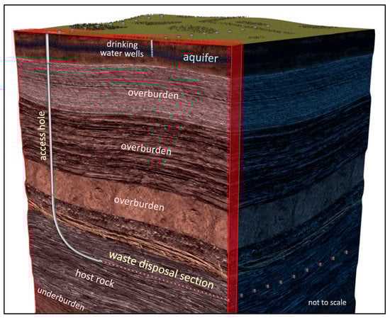
Figure 1.
Schematic of a deep horizontal drillhole repository (not to scale) with vertical access hole, gradually turning horizontal. The near-horizontal waste disposal section holds the canisters. A repository may consist of multiple drillholes; the red-shaded box indicates a symmetry cell.
With the exception of the first and last borehole of the array, the configuration shown in Figure 1 is symmetrical with respect to the vertical plane going through the borehole axis as well as the vertical plane half-way between two disposal sections. By making these planes impervious to fluid and heat flow and radionuclide transport, it is sufficient to simulate one such symmetry cell to appropriately represent the entire, multi-borehole repository system.
2.2. Integrated Modeling Approach
A single numerical model has been developed, which captures the main subcomponents of the repository system and their interactions in an integrated manner [45,46]. Furthermore, thermal–hydrological processes and their impact on radionuclide transport are fully coupled. Figure 2 shows the subcomponents and processes combined in this mechanistic safety analysis model of a generic horizontal borehole repository. The EBS and geosphere are both represented in their entirety and evaluated jointly using a shared set of governing equations, which promotes conceptual and parametric consistency and ensures that interactions and feedback mechanisms are inherently accounted for. (As will be discussed below, capturing such interactions between the borehole and the geological environment is essential to properly evaluate the role that backfilling and sealing play in the context of overall repository performance.) Heat and radionuclides are released from individually represented waste canisters and are transported within the various engineered components of the borehole. They also migrate and dissipate into the geological far field before they reach the near-surface aquifer and from there the biosphere. Processes in the biosphere are lumped into a dose coefficient of 1.1 × 10⁻⁷ Sv Bq−1 [47], which (combined with the water consumption rate) measures the radiological impact of ingesting water contaminated with radionuclides, assuming that the exposed individual drinks water exclusively from the well centered above the repository.
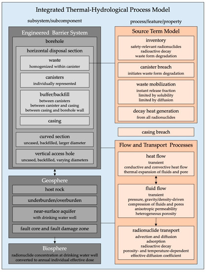
Figure 2.
System components and processes represented in an integrated thermal–hydrological model of deep horizontal borehole repository.
Integrating various repository components and accounting for coupled flow and transport mechanisms also requires that the model be capable of spanning a wide range of spatial and temporal scales while at the same time remaining computationally tractable. To meet these requirements, a model grid was constructed that consists of a high-resolution, two-dimensional, axial-radial near-field model of the borehole and its immediate surroundings, which is embedded in a conventional three-dimensional representation of the geological far-field. Figure 3 indicates that relevant small-scale features within the borehole are accurately depicted, such as the backfilled gap between the canister and the casing, the ½-inch (0.0127 m) thick casing, and the cemented annulus behind the casing. Moreover, despite its reduced dimensionality, the orientation and geometry of the near-field processes are well represented, including axial flow and transport with a changing gravitational component along the trajectory of the curved borehole, as well as radial diffusion of radionuclides and radial heat dissipation into the host rock. The Cartesian part of the mesh is suitable for calculating three-dimensional flow and radionuclide migration in a geosphere that consists of layered formations with internal random heterogeneities. Linking the axial–radial near-field mesh to a Cartesian far-field mesh results in a computational model that is accurate regarding the representation of the scale and geometry of its features and the expected gradients; moreover, it is computationally efficient.
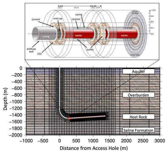
Figure 3.
Computational grid: (top) excerpt of the radial–axial grid of the near-field model, which follows the trajectory of the directionally drilled borehole and is embedded in the three-dimensional Voronoi grid of the geosphere model (bottom). A total of 153 waste canisters are individually represented in the sub-horizontal disposal section, which is at a depth of 1.5 km. A detailed description of the grid can be found in [46].
Computational efficiency is important for two reasons. First, the processes during the thermal period and after canister breach and radionuclide release are highly transient with steep gradients, which calls for a fine temporal resolution. In addition, repository performance must be evaluated over a very long period of several million years. As a result, the total number of time steps needed to calculate the evolution of the system is expected to be very large. Secondly, evaluating the impact of conceptual and parametric uncertainties on repository performance is computationally demanding, as many simulations are needed to perform sensitivity analyses or sampling-based uncertainty propagation analyses.
As an alternative to the integrated mechanistic modeling approach used here, the computational demand of a complex safety assessment model is often reduced by replacing it with a network of interlinked, simplified submodels with abstracted interfaces between them. While viable, the use of such interfaces may be considered problematic in that only a subset of the information is passed through to the downstream submodels, feedback mechanisms are usually not accounted for, and conceptual consistency is difficult to ascertain. We consider the fully integrated model, while sophisticated in its process description and detailed in the representation of subcomponents, to be more transparent, which is essential when using its results as part of the safety case for a nuclear waste repository.
The coupled thermal–hydrological and radionuclide transport processes occurring in the integrated source-term, near-field, far-field, and biosphere model described above are simulated using the iTOUGH2 simulation–optimization software [48], which is based on the TOUGH2 code for non-isothermal multiphase flow and transport in fractured-porous media [49,50].
2.3. Scenario Description
2.3.1. Reference Scenario
The importance of sealing the access and disposal sections of the borehole to ensure repository safety is examined by comparing the exposure dose obtained by a reference scenario with the dose calculated for an unlikely disruptive scenario, in which the backfill has poor sealing properties and considerable axial and vertical pressure gradients are imposed.
The reference scenario is essentially identical to that described in [45], with the exception that the repository is placed at a depth of 1.5 km. As before, the host rock is considered to be a 500 m thick sequence of sandy and clayey layers with a composite permeability of 10−17 m2 and a geostatistically generated, spatially variable porosity between 5% and 20%. A 1000 m thick overburden, acting as a poor-quality natural seal, with a relatively high permeability of 10−14 m2 separates the host rock from the critical zone and near-surface aquifer, from which drinking water is extracted. The underburden is conceptualized as a saline formation with a permeability of 3 × 10⁻¹⁶ m2, containing a NaCl brine with a salinity of 50,000 ppm. In the reference scenario, the borehole is backfilled with a material of permeability 10−16 m2 and a porosity of 30%. Permeabilities for the scenarios investigated below are summarized in Table 1; the complete set of hydrological, thermal, and transport parameters as well as a detailed description of initial and boundary conditions can be found in [46]. Table 2 summarizes the four main geological zones, describing their role in the context of nuclear waste isolation, along with related borehole sealing issues. Note that we refer to backfill with permeability greater than 10−13 m2 as “poorly-sealing”; it does provide some flow resistance, which is equivalent to that of a fine sand.

Table 1.
Permeabilities defining the differences between reference and disruptive scenarios.
Table 2.
Main geological zones and associated borehole sealing issues.
The initial temperature distribution follows an average geothermal gradient of 30 °C km−1 with a constant surface temperature of 13 °C. The initial pressure distribution is at equilibrium with the atmospheric conditions at the land surface and the saline formation, which is overpressured by 10 bars with respect to hydrostatic conditions with a temperature- and salinity-dependent fluid density. The overpressure is supplied at the lower-right corner of the model over a quarter of its length.
This configuration with an overpressured saline formation is a conservative feature selected to promote flow diagonally upward throughout the entire repository system, pushing contaminated fluid horizontally along the disposal section and then upwards along the vertical access hole. Such modest overpressures encountered in deeper sedimentary rocks may derive from a local or regional, geometrically imposed fluid dynamic pressure transfer, such as gas migration updip along an inclined reservoir. Not only in areas with high structural relief, but also in low-relief deltaic environments, compaction disequilibrium may cause large pressure compartmentalization, leading to undercompacted shales that exhibit high overpressures [51,52]. Hydrocarbon generation (with fluid or gas expansion) has been described as a pressure generator [53], and diagenesis (clay smectite-illite transformation), tectonic compression, and pressure transfer can all play important roles. Finally, the advancement and retreat of thick ice sheets during transitions between glaciation and inter-glaciation periods also lead to changes in effective stress and pore pressures between units of different compressive strength [54,55,56,57].
As discussed in [45,46], the magnitude and orientation of the regional pressure gradient is one of the most influential factors affecting peak dose. While the model considered here is a conceptual test of the impact of the repository being located in a regional upflow zone, and that significant faulting redistributes deeper pressure for a prolonged time, it is worth noting that deeper rocks are not necessarily overpressured. In fact, the deep injection of fluids or gas is facilitated by relatively underpressured rocks [58]. An overpressured saline formation is considered here as a conservative scenario, even though near-basement, regionally underpressured sedimentary rocks [57] that naturally limit the upward migration of fluids may serve as preferential repository sites.
2.3.2. Disruptive Scenarios
The potentially detrimental effects of a low-quality borehole backfill on repository performance is examined by making three conceptual changes, where the first change concerns backfill properties, the second concerns the geologic environment, and the third concerns canister performance.
First, the buffer and backfill materials are assumed to have a high permeability of 10−13 m2, either by design—i.e., no hydraulic safety function is assigned to these materials—or as a result of thermal, mechanical, or chemical degradation processes [21,28,59,60], which generate leakage pathways in the backfill itself or along the interface between the backfill and the formation. Because the buffer has no hydraulic barrier function in this scenario, it is simply referred to as backfill, so is the material in the access hole. Furthermore, formation damage around the borehole leads to a potential annular leakage pathway, the so-called drilling disturbed zone (DDZ), which is also referred to as the excavation disturbed zone (EDZ) in the context of mined repositories. It is assumed that rock welding [61] or cement-grouting of fractures [62] within the DDZ has been ineffective, i.e., DDZ permeabilities remain two orders of magnitude higher than the permeability of the formation the borehole penetrates.
Second, a seismic event is assumed to have reactivated two subvertical faults, one intersecting the waste disposal section near the curved section of the borehole, and the second near the borehole’s dead-end. Both faults originate below the host rock, so fluids entering the faults are pressurized given the overpressure in the deeper saline formation. The first fault ruptures the land surface, whereas the second fault terminates within the overburden, preventing outflow and thus creating a pressure gradient along the axis of the waste disposal section, which—if not sealed—acts as a preferential conduit that connects the two faults. Both faults are conceptualized as having a fault core with a high transmissivity of 5 × 10⁻⁵ m2 s−1, which is centered within a fractured damage zone with a permeability that declines from the fault’s core value to the undisturbed value of the formation it intersects at a distance of 25 m. The faults are activated immediately after repository closure and are assumed to remain open throughout the performance period up to 10 million years. The sustained hydraulic conductivity of the fault over the performance period is a conservative assumption. In most cases, faults will remain open and conductive after rupture for a time interval that is short in comparison to the repository performance period, unless reactivated by recurring earthquakes.
As a variant of the seismic scenario with two activated faults, we also consider the case where only one fault intersects the repository. This fault is assumed to terminate within the low-permeability host rock, thus limiting pressure dissipation into the higher-permeability overburden. In this sub-scenario, the repository borehole is the only preferred pathway into which the pressurized brine can flow, potentially exacerbating the detrimental impacts of a poorly-sealing backfill material.
In general, seismic events may impact the repository performance in several ways, including (1) uplift and thus exposure of the repository, (2) disruption of emplaced waste canisters, (3) changes in the material properties of deformation structures, (4) changes in local and regional hydraulic heads, and (5) groundwater composition [63]; the scenario simulated here accounts for issues (2)–(4).
Third, it is assumed that all canisters have been breached immediately after repository closure due to the effects of the earthquake. This means that waste degradation is initiated, and the release of radionuclides starts immediately. Note that it has been previously demonstrated that an early-canister-failure scenario (and the even more conservative assumption of instant mobilization of the entire inventory) has only a minor effect on the long-term performance of the repository [45,46].
This two-fault configuration and the very particular one-fault scenario along with the associated assumptions about early waste mobilization and low flow resistance of the backfill material are highly unlikely. It can be considered artificial; the combination was devised specifically to provide a bounding scenario that meets the particular purpose of this study. Nevertheless, faults and smaller water-conducting features of various sizes are commonly present throughout otherwise low-permeability rock formations. Thus, the careful mapping of such features is an important aspect of site characterization of a nuclear waste repository; they are typically included in conceptual and numerical models, either deterministically or using stochastic methods [64]. Large extant features are easily detected, in which case they are a disqualifying criterion for site selection. However, if strain rates are low and faults lack surface expressions, they may be more difficult to identify, unless high-quality subsurface data are available. Moreover, while they may not be near the repository and thus not detected during the drilling and logging of the disposal borehole, these water-conducting features may be stimulated by a large earthquake and propagate into the repository block after repository closure. The magnitude of the earthquake needed to reactivate faults of the size postulated here has been estimated from paleoseismological records or empirical scaling relationships of active faults, which relate fault length or slip to observed seismicity [65]. Such estimates indicate that earthquakes with a magnitude on the order of M > 6 are sufficient to generate faults with lengths of several kilometers [66]. Even more challenging is the determination of the hydraulic properties of such faults, which greatly depend on the rupture mode, mineralogy, stress condition, and other factors [67]. Nevertheless, while faults with high transmissivities (such as the one selected here) are infrequent, they are not unrealistic [68]. During fault reactivation, fluid pressures may be considerably perturbed within and immediately adjacent to the fault. However, such perturbations are typically very short-lived [69] and are therefore not included in the model.
Figure 4 shows the porosity distribution within the symmetry cell that comprises the numerical model used for the analyses. It reveals the large-scale hydrostratigraphy and the location and extent of the faults. The trajectory of the borehole is also rendered, with the disposal section indicated by a red sub-horizontal line.
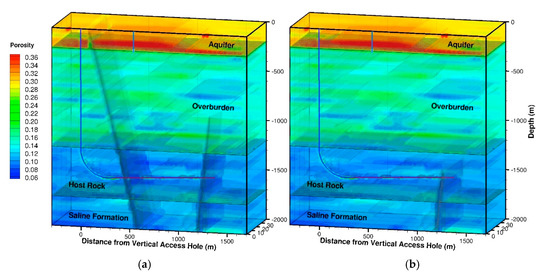
Figure 4.
Porosity distribution within modeled symmetry cell, showing hydrostratigraphy and location and extent of (a) two faults and (b) one fault intersecting the sub-horizontal disposal section of the borehole repository. Note that the actual model domain extends in the X-direction from −2200 to 3550 m. Applying symmetric boundary conditions at the X-Z planes is equivalent to the assumption of an infinite number of wells spaced 100 m apart in the Y-direction.
2.3.3. Performance Measures
The impact of borehole sealing on repository performance is evaluated by comparing the peak dose of 129I for the reference scenario and the seismic scenarios combined with a high-permeability backfill material. 129I was selected as the radionuclide of interest because it is expected to be the main contributor to the total peak dose. It has a relatively high initial inventory, high solubility limit, low adsorption coefficient, and long half-life of 1.57 × 10⁷ years, which leads to minimal decay even though the travel times from the repository to the accessible environment are very long. 129I has been identified as one of the most safety-relevant radionuclides in other, comprehensive safety analyses for repositories in argillaceous formations under reducing conditions [70,71,72]. 129I is also the main safety-relevant radionuclide predicted to emerge at the top of a deep vertical borehole repository [10]. Finally, using a single proxy radionuclide also appears suitable, as the focus of this study is on the relative differences between a well and poorly sealed access hole rather than on the absolute dose value.
In the simulations, each of the 153 individually represented waste canisters has an initial 129I inventory of 0.136 kg, with 20% of this inventory being released instantaneously from the canisters, which are breached immediately after repository closure due to the seismic event. The rest of the inventory is released slowly as the waste form degrades. A relatively high fractional waste degradation rate of 10−5 yr−1 is used based on [73]. The released 129I is fully dissolved in the pore water, from where it migrates by advection and diffusion. The diffusion coefficient in bulk water at 25 °C is set to 2 × 10⁻⁹ m2 s−1; it is adjusted for the higher temperatures experienced during the thermal period according to the Stokes–Einstein equation [74]. The Millington–Quirk model [75] is used to calculate the effective diffusion coefficient in a porous medium. An adsorption coefficient of 10−5 m3 kg−1 is assumed in the geosphere. No credit is taken for the adsorption of 129I within the EBS.
The decay heat generated by all radionuclides in a PWR spent nuclear fuel assembly with an initial enrichment of 4.5%, a burn-up of 50 GWd/MTIHM (gigawatt days of thermal energy production per metric ton of initial heavy metal), and a cooling time of 30 years [32] is supplied as a time-varying heat source to each of the canisters. The initial heat output is approximately 625 W per canister, declining to about 25 W per canister after 1000 years. The temperature increase lowers the density and viscosity of the pore fluids and thus has the potential to induce buoyancy-driven flow during the thermal period.
The processes described here (and in more detail in [45,46,76]) are simulated for the reference scenario as well as for two versions of the seismic-event scenario, the first with the borehole properly backfilled (referred to as well-sealing backfill), and the second assuming the backfill has a high permeability of 10−13 m2 and thus poses little resistance to fluid flow (referred to as poorly sealing backfill). In summary, the following scenarios have been simulated and will be discussed:
- Reference or Nominal Scenario (Section 3.1)
- Two-Fault Scenario with Well-Sealing Backfill (Section 3.2)
- Two-Fault Scenario with Poorly-Sealing Backfill (Section 3.3)
- One-Fault Scenario with Well-Sealing Backfill (Section 3.4)
- One-Fault Scenario with Poorly-Sealing Backfill (Section 3.5)
3. Results and Discussion
3.1. Reference Scenario
We first briefly discuss the results of the reference scenario. Figure 5 visualizes the spatial distribution and temporal evolution of the simulated 129I activity in the pore water, thus indicating the migration of this mobile, safety-relevant radionuclide from the repository through the EBS and geosphere to the near-surface aquifer from which groundwater is extracted for drinking water purposes. The distribution at early times (10,000 and 50,000 years after repository closure) highlights the diffusion-dominated transport mechanism within the shale host rock. However, the fact that the plume center is displaced upwardly (as seen at later times from 100,000 to 1,500,000 years) reveals the presence of an advective transport component. The overpressure in the saline formation induces fluid flow even in the low-permeability shale. Advective transport is more pronounced in the overburden and aquifer, as indicated by the influence of the point sink created by the continually pumping drinking water well. It should be noted that the permeabilities of both the host rock and the overburden were selected to be relatively high in order not to overrate the performance of the repository. Formations selected for siting a DHBR will likely have lower permeabilities, leading to diffusion-dominated radionuclide transport with a smaller advective component than considered here.
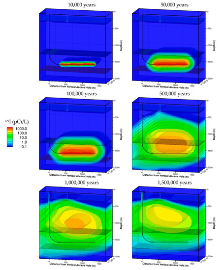
Figure 5.
Distribution of 129I activity at different times for reference scenario. The drinking-water well is indicated by the narrow vertical line that extends from the surface to 200 m depth.
The results shown in Figure 5 are similar to those discussed in [45], with a system behavior qualitatively between that of the nominal scenario and the high-vertical-gradient case, which is adjusted for the greater repository depth. The repository performance of this scenario serves as the reference against which the impact of a seismic event is evaluated. The role of the buffer and backfill, which is examined in the following subsection, is expected to play a greater role in this disruptive scenario than in the reference scenario.
3.2. Two-Fault Scenario with Well-Sealing Backfill
The seismic activation of two faults is assumed to lead to early canister failure and the advective transport of released radionuclides along the highly permeable fault cores and associated highly fractured damage zones into the overburden. As shown in Figure 6, 129I migration is initially faster along the fault on the right, as this fault is closer to the high pressures specified on the right of the saline formation. However, at later times, the contaminant front propagates farther upwards along the longer fault on the left, because it is connected to the highly permeable aquifer close to the atmospheric conditions at the land surface, whereas the shorter fault terminates within the comparably low-permeable overburden. The region within the host rock bounded by the two faults as well as the over- and underburden becomes a hydraulic stagnation zone. Radionuclides leave this region predominantly by diffusing from the host rock into the fault zones, which carry relatively uncontaminated brine from depth through the host rock to the overburden. In this scenario, the access hole is sealed, but it is surrounded by a DDZ with a 100-times higher permeability than the surrounding formation. No preferential transport along the curved section is noticeable at early times. At late times, the access hole is in contact with groundwater at elevated 129I activity. However, this contamination did not originate from the borehole, but is the result of lateral migration—by both advective and diffusive transport—away from the overpressured fault, which has a much greater contact area with the overburden than does the access hole. This effect transfers 129I from the overburden into the vertical access hole; only a small fraction of the overall radionuclide budget arrives at the aquifer via this pathway.
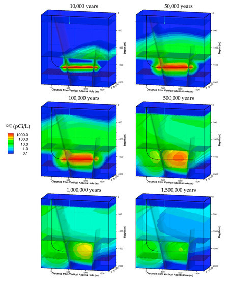
Figure 6.
Distribution of 129I activity at different times for a two-fault scenario with well-sealing backfill.
3.3. Two-Fault Scenario with Poorly-Sealing Backfill
The results from the main scenario of interest are visualized in Figure 7. Here, the backfill in the vertical and curved sections of the access hole as well as the horizontal waste disposal section is of relatively high permeability, i.e., it does not fulfill a hydraulic sealing function. As a result, radionuclides released from the breached waste canisters are displaced axially along the curved section, driven by the overpressure from the left fault intersecting the repository. This preferential flow and advective transport of 129I along the borehole is most evident after 10,000 years (see the first panel in Figure 7); it is also highlighted in Figure 8, which shows the early-time radionuclide transport from the disposal section along the curved and eventually vertical access hole, along with its radial penetration of the surrounding host rock and overburden.
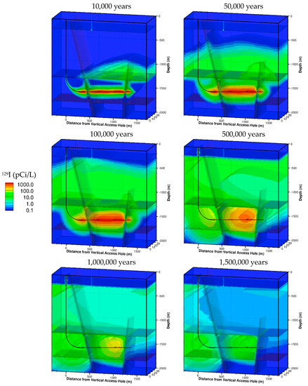
Figure 7.
Distribution of 129I activity at different times for two-fault scenario with poorly-sealing backfill.
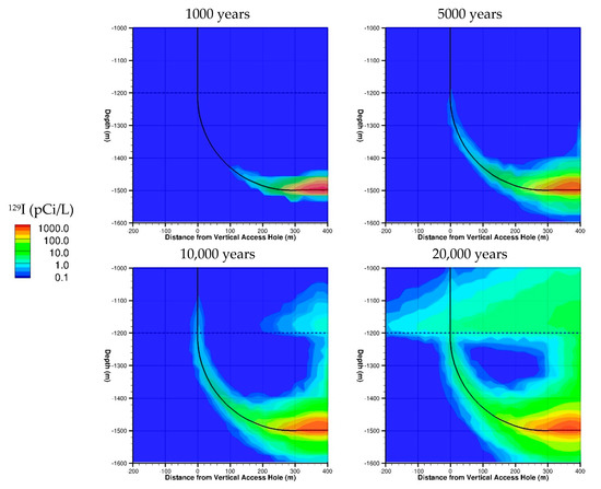
Figure 8.
Distribution of 129I activity at different times near access borehole for disruptive scenario with poorly-sealing backfill. Note that the vertical scale ends 1 km below the surface. Diffusive and advective losses from the access hole to the surrounding rock formations result in very small fluid flow and radionuclide-transport rates in the upper reaches of the access hole.
The activity in the near field of the access hole has the shape of a curved cone, which is the result of diffusive losses of 129I from the borehole into the tight host rock. Once radionuclides enter the vertical section, radial fluid losses from the overpressured access hole into the higher-permeable overburden and associated advective removal of 129I supplement the diffusive losses. Consequently, the vertical flow velocity in the borehole reduces exponentially, and so does the 129I concentrations within the upwards-flowing water. After a very short flow distance within the vertical access hole, the axial flow rate and radionuclide concentrations within the vertical access hole are very small, and the vertical migration of 129I essentially ceases. This is a result of the fact that the cross-sectional area available for radial losses changes linearly as contaminated water flows up the access hole, whereas the circular area for transport along the axis of the borehole is both small and remains constant. This interpretation is consistent with a similar calculation of diffusive losses from a deep vertical borehole made with a cylindrical submodel [10].
However, these advective and diffusive rates of radial fluid and radionuclide losses become smaller with time, as pressure and concentration gradients decline. Moreover, as shown in Figure 7 and Figure 8, the overpressured fault pushes contaminated water toward the vertical access hole. Consequently, the radial transport of water and radionuclides away from the access hole decreases, and the process is eventually reversed at higher elevations, where contaminated water emanating from the fault enters the access hole. Furthermore, the top of the access hole is slightly underpressured due to the continuous pumping from the drinking water well. As a result, while decreasing in the lower parts of the access hole, the vertical fluid flow and radionuclide transport increase again in the upper parts once the 129I plumes migrating in the fault and overburden approach the aquifer.
It should be noted that this intricate temporal and spatial evolution of fluid flow and associated radionuclide transport in the access hole would not be predicted if a simple, separate submodel of the borehole and its surroundings were used to estimate the release of radionuclides to the aquifer. The pressure and concentration distributions strongly depend on the connections among the access hole, fault, overburden, aquifer, and drinking water well. The integrated modeling approach captures the associated feedback mechanisms, leading to a qualitatively different understanding and quantitatively different result compared to a cylindrical model of the access hole and the adjacent formation, specifically if the results of such a calculation were abstracted and introduced as source terms into a geosphere model.
3.4. One-Fault Scenario with Well-Sealing Backfill
A scenario in which a single, short fault intersects the disposal section can highlight the differences between a well-sealed and poorly sealed borehole. Placing the fault near the borehole’s dead-end maximizes the amount of contaminated groundwater that could be pushed toward the curved and vertical sections of the borehole. Moreover, the axial pressure gradient within the horizontal disposal section is higher than in the two-fault scenario, as the overpressure imposed by the first fault is not balanced by the overpressure in the second fault. As before, we make the conservative assumption that the overpressure from this fault persists for the entire duration of the simulation. Finally, the pressure as well as radionuclides are not readily dispersed into the overburden through the two faults; the poorly-sealing backfill is essentially the only preferential pathway for the advective transport of radionuclides.
Figure 9 shows the evolution of the 129I activity plume. Since the buffer in the disposal section and the backfill in the access hole fulfill their hydraulic sealing functions, no preferential fluid flow and radionuclide transport along the borehole occurs. However, the comparison with the reference scenario (see Figure 5) indicates that the overpressure transmitted by the fault leads to increased advective radionuclide transport even within the host rock; this is evident especially at late times, after radionuclide releases from the waste form have stopped, and a front emerges between uncontaminated brine and the displaced 129I plume. Moreover, site-scale changes in the pressure field lead to a displacement of the plume center to the left.
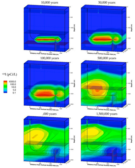
Figure 9.
Distribution of 129I activity at different times for one-fault scenario with well-sealing backfill.
3.5. One-Fault Scenario with Poorly-Sealing Backfill
The transport pattern for the case of a poorly-sealing backfill is visualized in Figure 10. Since the short fault terminates within the low-permeability host rock, the overpressure transmitted from the saline formation through the fault is directed into the borehole, pushing contaminated groundwater along its axis toward the vertical access hole. Once it encounters the more permeable overburden, radionuclides are radially lost to the formation by both advective and diffusive transport. As described above, the axial flow of water is exponentially reduced along the flow direction, slowing the migration of contaminated water up the access hole. Even after 100,000 years, the contamination front has advanced only about half the distance from the top of the host rock to the bottom of the near-surface aquifer. After 500,000 years, the overall shape of the contaminant plume is again dominated by the transport processes in the geosphere, with no distinct pattern overprinted from the access hole. Some radionuclides do reach the aquifer through the poorly sealed access hole, mainly because the drawdown in the aquifer caused by the pumping well leads to an upwards head gradient within the borehole. However, the contribution to the total activity from the access hole is minor due to the very small cross-sectional area of the access hole, which only allows for a small leakage rate compared to the wells pumping rate.
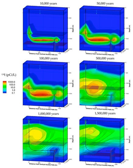
Figure 10.
Distribution of 129I activity at different times for one-fault scenario with poorly-sealing backfill.
3.6. Performance Comparison
The simulations discussed in the previous subsections demonstrate that a fraction of the radionuclides released from the waste canisters are transported along the curved and vertical sections of the access hole. However, only a small portion eventually reaches the near-surface aquifer. Recall that the purpose of this study is to examine whether this leakage fraction is significant, and if so, whether it is essential to backfill the borehole with a sealing material that will have sufficiently low permeability for periods far outside the range of engineering experience. These questions are answered by comparing the results obtained for the three studied scenarios: The nominal scenario and the fault-activation scenarios with a well-sealing and poorly-sealing backfill material. The performance metrics examined are the radionuclide flux at different locations along the migration pathway (see Figure 11) and the maximum annual dose of an individual exposed to contaminated groundwater (see Figure 12).
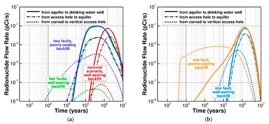
Figure 11.
129I activity flow rates along vertical access hole with sealing and poorly-sealing backfill for (a) reference and two-fault scenario, and (b) one-fault scenario.
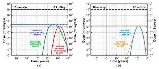
Figure 12.
Annual exposure dose with well-sealing and poorly-sealing backfill for (a) reference and two-fault scenarios, and (b) one fault scenario.
The dotted lines in Figure 11 indicate the rate at which radionuclides enter the bottom of the vertical access hole at a depth of −1200 m. We first consider the case where a disruptive seismic event reactivates two faults, causing early canister failure and providing an axial head gradient; the two-fault scenarios are shown in Figure 11a. If the borehole is sealed, no significant flow along the curved section occurs (green dotted line). However, if the borehole is only poorly sealed, radionuclides start entering the access hole relatively early (around 1000 years after repository closure) and reach a maximum rate of 10−4 pCi s−1 (blue dotted line).
The second point of interest is the activity flow rate from the vertical access hole into the near-surface aquifer, as shown by dash-dotted lines in Figure 11a. For both scenarios—with a well-sealing and poorly-sealing backfill material—the maximum outflow rate is about 6 × 10⁻³ pCi s−1, i.e., it is considerably higher than the inlet flow rates at the bottom of the access hole. This confirms that most of the radionuclides enter the slightly underpressured vertical access hole radially from the contaminated overburden rather than directly through preferential axial flow from the disposal section. The difference between the cases with a well-sealing and a poorly-sealing backfill are relatively small because the DDZ around the access hole (with a permeability two orders of magnitude higher than the geological formation) remains the dominant axial channel in this parallel-flow configuration.
Finally, the solid lines in Figure 11a show the 129I inflow into the drinking water well. For the nominal case, the peak rate of 5 × 10⁻² pCi s−1 is about half the peak rates for the disruptive scenarios. Only about 6% of the 129I produced by the well entered the aquifer through the access hole and its surrounding DDZ, even if the borehole is not sealed and a seismic event occurred. The majority of the radionuclides enter the aquifer and the well through the faults and through the contact with the overburden. The outflow from the vertical access hole into the aquifer is dominated by the contribution from the overburden, which far exceeds the direct contribution from the repository through the curved borehole pathway.
The results from the one-fault scenario are shown in Figure 11b. Recall that the driving force in the one-fault scenario is considerably stronger than in the two-fault scenario, because the short fault terminates within the tight host rock. With the borehole being the only high-permeability pathway for pressure release, radionuclides leaking from breached canisters emplaced along the entire disposal section are persistently pushed along the backfilled borehole. They eventually enter the bottom of the vertical access hole, reaching a maximum rate of 5 × 10⁻⁴ pCi s−1 after 500,000 years if the backfill is sealing (blue dotted line in Figure 11b), and reaching close to 10−3 pCi s−1 after 30,000 years if the backfill is poorly-sealing (orange dotted line in Figure 11b). As expected, radionuclides migrating along the poorly sealed access hole are the first to reach the aquifer (orange dashed-dotted line); they are also the main contributor to the 129I activity rate at the drinking water well (orange solid line) up to about 200,000 years. However, at this time, the rate of 10−3 pCi s−1 is very small, almost two orders of magnitude lower than the maximum rate at the well of 10−1 pCi s−1 encountered after 1.4 million years. For both the well-sealing and poorly-sealing cases, radionuclides migrating along the access hole contribute about 20% to the total activity rate in the well.
The ultimate performance measure is the annual radiological peak dose to which an individual living at the repository site is exposed. As shown in Figure 12a, the peak dose for the nominal scenario occurs after 1.5 million years and is estimated to be 1.3 × 10⁻⁴ mSv yr−1, which is about half the peak exposure rates of 2.3 × 10⁻⁴ mSv yr−1 for the two-fault scenarios, realized after 0.5 million years. This difference between the nominal and disruptive scenarios reveals the impact that the seismic event and associated fault reactivation has on repository performance. As discussed in more detail in [45,46], a high-permeable fault triggers a faster, advective migration of radionuclides from the repository to the accessible environment, but at the same time, it leads to greater spatial and temporal dispersion of the contaminants over the geosphere, thus reducing the maximum concentrations within the plume and the peak concentration of the broadened breakthrough curve. Consequently, the larger dispersion dampens the detrimental impact that preferential flow along the fault zones would otherwise have.
The differences between the well-sealing and poorly-sealing backfill cases are insignificant, because only a small percentage of the radionuclides arriving at the drinking water well have traveled through the access hole, and these rates are dominated by radial 129I inflows from the overburden into the DDZ of the upper parts of the access hole rather than axial transport along the borehole from the disposal section to the aquifer. Backfilling the borehole is likely to have a greater impact on repository performance if it could be demonstrated that it also effectively seals the DDZ. The assumption that the borehole is surrounded by a highly permeable DDZ that persists over the entire simulation time is considered conservative regarding the calculated exposure dose but may have led to an underestimation of the benefits of sealing the access hole.
The exposure dose from the one-fault scenario is shown in Figure 12b. While the case with a poorly-sealing backfill leads to an earlier arrival of radionuclides, the peak dose value is not affected by the backfill properties and is only slightly higher than that of the nominal scenario. Unlike in the two-fault scenario, the peak dose also occurs at about the same time as in the nominal scenario. This indicates that the changes in the dose curves seen for the two-fault scenario are dominated by the faults rather than the backfill properties of the access hole; the short fault terminating in the host rock has no such impact on the overall dispersion of the bulk of the radionuclide plume.
4. Summary and Concluding Remarks
The concept of waste disposal in deep horizontal boreholes consists of a system of multiple engineered and natural barriers. In this system, the main engineered components are the waste form itself and the canisters. Conversely, in a relatively shallow mined repository, considerable safety functions must be assigned to the buffer surrounding the canisters, which is expected to chemically and mechanically protect the waste packages and to retard the migration of radionuclides once they are released from the breached canisters. A borehole repository does not afford the space necessary to hold a buffer sufficiently thick to make it an effective barrier, and its emplacement is challenging. Therefore, only backfills with a limited hydraulic sealing function are considered, including a bounding case of a highly permeable backfill.
The greater depth and the larger length-to-diameter aspect ratio of the access borehole in a DHBR both contribute to considerably improved passive repository safety. In particular, the great depth reachable by boreholes allows the repository to be separated from the drinking water aquifer and places it in a hydrogeological environment that has been isolated from near-surface impacts for a very long time. Each individual borehole terminates in a dead-end within the tight host formation, limiting the amount of water that can enter the borehole. This linear arrangement also disallows fluid circulation within an extensive network of access and deposition tunnels. Should the sealing of an access borehole be compromised, only the radionuclides from a fraction of a single disposal section may migrate toward the vertical access hole. For such axial flow and transport to occur, a properly oriented head gradient must exist, and a water-conducting feature needs to intersect the repository, which is capable of supplying sufficient and sustained fluid flow into the disposal section. Only the radionuclides released from canisters placed between this inflow point and the curved section of the access hole would be mobilized. Moreover, the waste disposal section is spatially separated from the vertical access hole. Vertical buoyancy forces generated during the thermal period are not aligned with the horizontal orientation of the disposal section where they are created, and they are spatially removed from the vertical access hole. Therefore, driving forces from thermal effects are insignificant in a horizontal borehole repository.
These design features suggest that borehole sealing may not be of great relevance for the performance of a DHBR. This premise has been examined by devising scenarios that promote axial flow along the borehole, potentially carrying radionuclides from the disposal section to the accessible environment at high rates or high concentrations. The examined scenarios are very unlikely or perhaps even unrealistic but were chosen to create conditions that circumvent the inherent safety features of the borehole repository design. Reactivated faults were introduced to supply ample water into the disposal section at elevated pressures, generating a sustained axial head gradient. The backfill material is considered degraded or otherwise of high permeability, providing little resistance to fluid flow and the advective transport of radionuclides, which are released from canisters assumed to have failed during the seismic event. All flow and transport processes have been calculated in an integrated numerical model that accounts for interactions and feedbacks among the various engineered and natural components of a geologic repository system.
Our modeling indicates that the addition of a backfill with low permeability in a DHBR does not significantly improve safety, even in situations in which the underburden is overpressured and one or two earthquake faults intersect the disposal section to drive contaminated fluid toward the access hole. Foremost, the calculated peak exposure dose is far below an assumed dose standard of 0.1 mSv yr−1, despite making cautious assumptions about most aspects of the repository system [46], specifically its position above an overpressured saline formation. The seismic scenarios with two faults lead to slightly higher dose rates than the reference scenario because of (1) the assumption of early canister failure and (2) the generation of a pathway for preferential fluid flow and radionuclide transport from the repository to the aquifer through reactivated fault zones. Furthermore, the two-fault configuration allowed radionuclides to be pushed axially along the disposal section toward one of the faults as well as into the access hole. The scenario with a single, short fault that intersects the repository but terminates in the tight host rock supplies the strongest axial push and displacement of contaminated groundwater along the access hole. However, the large ratio of the cylindrical to the cross-sectional areas of the borehole leads to advective and diffusive losses of radionuclides into the overburden, drastically reducing the axial rate of fluid flow and radionuclide transport with increasing upwards migration distance.
The cases with and without a sealing backfill yield essentially identical peak doses, because only a small fraction of the radionuclides produced by the drinking water well enter the aquifer through the access hole, whereas the majority enters through the fault and the contact area with the overburden, which is substantially larger than the cross-sectional area of the access hole. Moreover, the radionuclides found in the upper parts of the slightly underpressured access hole were drawn from the surrounding overburden having low contaminant concentrations rather than originating directly from the disposal section. The negligible impact of the borehole backfill may also partly be due to the assumption that a highly permeable DDZ exists throughout the simulation period. Should the DDZ heal with time, the relative benefit of borehole sealing would be more pronounced.
The small impact of borehole backfill on exposure dose suggests that the role of the access hole as a preferential leakage pathway for radionuclides from the repository to the accessible environment is considerably less important than anticipated, which is a conclusion supported by other studies of borehole leakage in the context of nuclear waste isolation. The main reason for its limited impact is the geometrical fact that the borehole’s cross-sectional area is extremely small in comparison to the areas and very large volumes of the geosphere into which radionuclides can diffuse, specifically if the repository is located at great depth. Axial transport along the access hole may only become relevant if it is advective with a very large flow rate. Such flow rates are unlikely to develop given that the disposal section of the repository is embedded in a host rock of very low permeability and that the borehole terminates in a dead-end within this tight formation, preventing any persistent throughflow of fluids. Moreover, a strong and persistent driving force would need to be present and appropriately oriented. Finally, the specific features and conditions that could enable considerable axial flow rates would need to persist over very long time frames.
The sealing of boreholes for the protection of freshwater aquifers is required by existing regulations in many nations. Following standard practice, hydraulic feed or thief zones identified during drilling and borehole logging may be plugged, and the borehole’s DDZ may be grouted at certain intervals. According to [33], boreholes and their associated DDZs can be effectively sealed, whereas the long-term sealing effectiveness of large emplacement tunnels and access structures and their extensive EDZs is very difficult to assess.
This paper examines the consequences of an earthquake for the components of a horizontal borehole repository that behave differently from deep vertical boreholes or shallower mined repositories. It shows that the geosphere and its interaction with a small-diameter borehole lead to a robust barrier system for waste containment, even under an unlikely disruptive scenario in which readily identifiable hazards (such as major faults and seismic risks) are assumed to be overlooked during site selection, and that engineering components (canisters and borehole seals and backfill) fail to perform as expected.
Sealing and backfilling the access borehole is straightforward and sensible. However, the long-term effectiveness of borehole sealing is difficult to assess or predict. Therefore, it is reassuring that—due to (a) the passive safety afforded by its design, (b) the effectiveness of diffusive and advective losses into the overburden, caused by the high length-to-diameter aspect ratio of the borehole, and (c) the small cross-section of the borehole in comparison to the repository footprint—a deep horizontal borehole repository does not need to rely on the long-term integrity of its seals and backfill material.
Ultimately, repository safety depends on judicious site selection based on the comprehensive characterization of geological and hydrological properties and conditions, and the achievement of project execution standards. Understanding the relevant conditions that jeopardize containment requires careful evaluation and analysis. The acquisition of high-quality subsurface data will be necessary to inform the risk and safety expectations. It will be important to develop criteria to rate containment risk and differentiate opportunities for inherent repository safety from poor choices. It is within this context that the work presented in this paper provides insights into the performance and safety functions of the vertical access hole seals in a deep horizontal borehole repository.
5. Patents
The basic approach is patented by Deep Isolation, Inc.: U.S. patent 10,002,683 B2.
Author Contributions
Conceptualization, S.F., R.A.M., C.C., J.G. and J.A.; Formal analysis, S.F.; Investigation, S.F., R.A.M., C.C., J.G. and J.A.; Methodology, S.F.; Project administration, R.A.M.; Software, S.F.; Supervision, R.A.M.; Visualization, S.F.; Writing—original draft, S.F. and C.C.; Writing—review and editing, R.A.M., J.G., and J.A. All authors have read and agreed to the published version of the manuscript.
Funding
This research was supported by Deep Isolation Inc.
Institutional Review Board Statement
Not applicable.
Informed Consent Statement
Not applicable.
Data Availability Statement
Data used for this generic modeling study are cited in the paper.
Acknowledgments
The authors thank the anonymous reviewers for their constructive comments and valuable suggestions.
Conflicts of Interest
S.F. and J.A. are paid consultants for Deep Isolation, Inc.
References
- Muller, R.A.; Finsterle, S.; Grimsich, J.; Baltzer, R.; Muller, E.A.; Rector, J.W.; Payer, J.; Apps, J. Disposal of High-Level Nuclear Waste in Deep Horizontal Drillholes. Energies 2019, 12, 28. [Google Scholar] [CrossRef]
- Sievänen, U.; Karvonen, T.H.; Dixon, D.; Hansen, J.; Jalonen, T. Design, Production and Initial State of the Underground Disposal Facility Closure; Posiva Oy: Eurajoki, Finland, 2012; p. 112. [Google Scholar]
- Keto, P.; Dixon, D.; Jonsson, E.; Gunnarsson, D.; Börgesson, L.; Hansen, J. Assessment of Backfill Design for KBS-3V Repository; Svensk Kärnbränslehantering AB (SKB): Stockholm, Sweden, 2009; p. 119. [Google Scholar]
- Muller, H.R.; Garitte, B.; Vogt, T.; Kohler, S.; Sakaki, T.; Weber, H.; Spillmann, T.; Hertrich, M.; Becker, J.K.; Giroud, N.; et al. Implementation of the full-scale emplacement (FE) experiment at the Mont Terri rock laboratory. Swiss J. Geosci. 2017, 110, 287–306. [Google Scholar] [CrossRef]
- Bosgiraud, J.-M.; Foin, R.; Bethmont, S. Full Scale Demonstration of Plugs and Seals-Report on FSS Shotcrete Plug Construction; Andra: Paris, France, 2016; p. 22. [Google Scholar]
- Hansen, J.; Holt, E.; Palmu, M. DOPAS: Full-Scale Demonstration of Plugs and Seal. In Proceedings of the Euradwaste′13: 8th EC Conference on the Management of Radioactive Waste, Community Policy and Research on Disposal, Vilnius, Lithuania, 14–16 October 2013; p. 8. [Google Scholar]
- Dixon, D.; Priyanto, D.; Hansen, J.; Farhoud, R.; Živkovic, A. The Enhanced Sealing Project (ESP): 2009–17 monitoring of a full-scale shaft seal installed in granitic rock. Geol. Soc. Lond. Spec. Publ. 2018, 482, 347–359. [Google Scholar] [CrossRef]
- Arnold, B.W.; Brady, P.V.; Bauer, S.J.; Herrick, C.; Pye, S.; Finger, J. Reference Design and Operations for Deep Borehole Disposal of High-Level Radioactive Waste; Sandia National Laboratories: Albuquerque, NM, USA, 2011; p. 67. [Google Scholar]
- Arnold, B.W.; Brady, P.; Sutton, M.; Travis, K.; MacKinnon, R.; Gibb, F.; Greenberg, H. Deep Borehole Disposal Research: Geological Data Evaluation; Alternative Waste Forms and Borehole Seals; Sandia National Laboratories: Albuquerque, NM, USA, 2014; p. 116. [Google Scholar]
- Arnold, B.W.; Brady, P.; Altman, S.; Vaughn, P.; Nielson, D.; Lee, J.; Gibb, F.; Mariner, P.; Travis, K.; Halsey, W.; et al. Deep Borehole Disposal Research: Demonstration Site Selection Guidelines, Borehole Seals Design, and RD&D Needs; Sandia National Laboratories: Albuquerque, NM, USA, 2013; p. 221. [Google Scholar]
- Arnold, B.W.; Vaughn, P.; MacKinnon, R.; Tillman, J.; Nielson, D.; Brady, P.; Halsey, W.; Altman, S. Research, Development, and Demonstration Roadmap for Deep Borehole Disposal; Sandia National Laboratories: Albuquerque, NM, USA, 2012; p. 151. [Google Scholar]
- NWTRB. Technical Evaluation of the U.S. Department of Energy Deep Borehole Disposal Research and Development Program; U.S. Nuclear Waste Technical Review Board: Arlington, VA, USA, 2016; p. 72. [Google Scholar]
- Pusch, R.; Ramqvist, G.; Knutsson, S.; Mohammed, H.M. Medium-deep or very deep disposal of highly radioactive waste? J. Civ. Eng. Archit. 2013, 7, 1548–1565. [Google Scholar]
- Sellin, P.; Leupin, O.X. The use of clay as an engineered barrier in radioactive-waste management-a review. Clays Clay Miner. 2013, 61, 477–498. [Google Scholar] [CrossRef]
- Kaufhold, S.; Dohrmann, R. Distinguishing between more and less suitable bentonites for storage of high-level radioactive waste. Clay Miner. 2016, 51, 289–302. [Google Scholar] [CrossRef]
- Nuclear Decommissioning Authority (NDA). A Review of the Development of Bentonite Barriers in the KBS-3V Disposal Concept; Nuclear Decommissioning Authority (NDA): Didcot, Oxford, UK, 2014; p. 84. [Google Scholar]
- Svensk Kärnbränslehantering AB (SKB). Long-Term Safety for the Final Repository for Spent Nuclear Fuel at Forsmark-Main Report of the SR-Site Project, Volume II; Svensk Kärnbränslehantering AB (SKB): Stockholm, Sweden, 2011; p. 278. [Google Scholar]
- Svensk Kärnbränslehantering AB (SKB). Long-Term Safety for the Final Repository for Spent Nuclear Fuel at Forsmark-Main Report of the SR-Site Project, Volume I; Svensk Kärnbränslehantering AB (SKB): Stockholm, Sweden, 2011; p. 271. [Google Scholar]
- Teodori, S.-P.; Rüedi, J.; Reinhold, M.; Manca, D. Design, Testing and Emplacement of Sand-Bentonite for the Construction of a Gas-Permeable Seal Test (GAST). In Proceedings of the ASME 2013 15th International Conference on Environmental Remediation and Radioactive Waste Management, Volume 1: Low/Intermediate-Level Radioactive Waste Management; Spent Fuel, Fissile Material, Transuranic and High-Level Radioactive Waste Management. Brussels, Belgium, 8–12 September 2013. [Google Scholar]
- Pusch, R.; Ramqvist, G.; Bockgård, N.; Ekman, L. Sealing of Investigation Boreholes, Phase 4; Svensk Kärnbränslehantering AB (SKB): Stockholm, Sweden, 2011; p. 51. [Google Scholar]
- Liu, X.D.; Prikryl, R.; Pusch, R. THMC testing of three expandable clays of potential use in HLW repositories. Appl. Clay Sci. 2011, 52, 419–427. [Google Scholar] [CrossRef]
- Rod, K.A.; Nguyen, M.T.; Elbakhshwan, M.; Gills, S.; Kutchko, B.; Varga, T.; McKinney, A.M.; Roosendaal, T.J.; Childers, M.I.; Zhao, C.H.; et al. Insights into the physical and chemical properties of a cement-polymer composite developed for geothermal wellbore applications. Cem. Concr. Compos. 2019, 97, 279–287. [Google Scholar] [CrossRef]
- Lavrov, A.; Torsæter, M. Physics and Mechanics of Primary Well Cementing; Springer: Berlin/Heidelberg, Germany, 2016; p. 111. [Google Scholar]
- Pusch, R.; Ramqvist, G.; Knutsson, S. Modern method for sealing deep boreholes. Eng. Geol. 2016, 202, 132–142. [Google Scholar] [CrossRef]
- Beswick, J. Borehole construction and operation for disposal in crystalline rocks. Radwaste Solut. 2017, 24, 28–32. [Google Scholar]
- Gibb, F.G.F.; McTaggart, N.A.; Travis, K.P.; Burley, D.; Hesketh, K.W. High-density support matrices: Key to the deep borehole disposal of spent nuclear fuel. J. Nucl. Mater. 2008, 374, 370–377. [Google Scholar] [CrossRef][Green Version]
- Gibb, F.G.F.; Travis, K.P.; Hesketh, K.W. Deep borehole disposal of higher burn up spent nuclear fuels. Mineral. Mag. 2012, 76, 3003–3017. [Google Scholar] [CrossRef]
- Mohammed, M.H.; Pusch, R.; Knutsson, S.; Warr, L.N. Hydrothermal alteration of clay and low pH concrete applicable to deep borehole disposal of high-level radioactive waste-A pilot study. Constr. Build. Mater. 2016, 104, 1–8. [Google Scholar] [CrossRef]
- Berner, U.; Kulik, D.A.; Kosakowski, G. Geochemical impact of a low-pH cement liner on the near field of a repository for spent fuel and high-level radioactive waste. Phys. Chem. Earth 2013, 64, 46–56. [Google Scholar] [CrossRef]
- Savage, D. A review of analogues of alkaline alteration with regard to long-term barrier performance. Mineral. Mag. 2011, 75, 2401–2418. [Google Scholar] [CrossRef]
- Clayton, D.; Freeze, G.; Hadgu, T.; Hardin, E.; Lee, J.; Prouty, J.; Rogers, R.; Nutt, W.M.; Birkholzer, J.; Liu, H.H.; et al. Generic System Modeling—Fiscal Year 2011 Progress Report; Sandia National Laboratories: Washington, DC, USA, 2011; p. 466. [Google Scholar]
- Ansolabehere, S.; Deutch, J.; Driscoll, M.; Holdren, J.P.; Joskow, P.L.; Lester, R.K.; Moniz, E.J.; Todreas, N.E. The Future of Nuclear Power: An Interdisciplinary MIT Study; Massachusetts Institute of Technology: Cambridge, MA, USA, 2003; p. 180. [Google Scholar]
- Pusch, R.; Knutsson, S.; Ramqvist, G.; Mohammed, M.H.; Pourbakjtiar, A. Can sealing of rock hosting a repository for highly radioactive waste be relied on? Nat. Sci. 2012, 4, 895–905. [Google Scholar] [CrossRef]
- Pusch, R.; Knutsson, S.; Al-Taie, L. The impact of hydraulic gradients and boundary conditions on the microstructural stability of clayey backfills with special respect to the risk of piping and erosion. J. Earth Sci. Geotech. Eng. 2012, 12, 89–112. [Google Scholar]
- Da Silva, D.V.A.; Jansen, J.D. A review of coupled dynamic well-reservoir simulation. In ISAPP (Integrated Systems Approach to Petroleum Production); IFAC-PapersOnLine: Amsterdam, the Netherlands, 2015; pp. 236–241. [Google Scholar]
- Ajayi, T.; Gupta, I. A review of reactive transport modeling in wellbore integrity problems. J. Pet. Sci. Eng. 2019, 175, 785–803. [Google Scholar] [CrossRef]
- Choi, Y.S.; Young, D.; Nesic, S.; Gray, L.G.S. Wellbore integrity and corrosion of carbon steel in CO2 geologic storage environments: A literature review. Int. J. Greenh. Gas Control 2013, 16, S70–S77. [Google Scholar] [CrossRef]
- Bachu, S.; Bennion, D.B. Experimental assessment of brine and/or CO2 leakage through well cements at reservoir conditions. Int. J. Greenhouse Gas Control 2009, 3, 494–501. [Google Scholar] [CrossRef]
- Ebigbo, A.; Class, H.; Helmig, R. CO2 leakage through an abandoned well: Problem-oriented benchmarks. Comput. Geosci. 2007, 11, 103–115. [Google Scholar] [CrossRef]
- Joyce, S.; Simpson, T.; Hartley, L.; Applegate, D.; Hoek, J.; Jackson, P.; Swan, D.; Marsic, N.; Follin, S. Groundwater Flow Modelling of Periods with Temperate Climate Conditions–Forsmark; Svensk Kärnbränslehantering AB (SKB): Stockholm, Sweden, 2010; p. 315. [Google Scholar]
- Bockgård, N. Hydraulic Effects of Unsealed Boreholes-Numerical Groundwater Flow Modelling of the Forsmark and Laxemar Sites; Svensk Kärnbränslehantering AB (SKB): Stockholm, Sweden, 2011; p. 63. [Google Scholar]
- Hadgu, T.; Arnold, B.; Lee, J.; Freeze, G.; Vaughn, P. Sensitivity analysis of seals permeability and performance assessment of deep borehole disposal of radioactive waste. In Proceedings of the Eleventh Probabilistic Safety Assessment and Management Conference (PSAM11) and the Annual European Safety and Reliability Conference (ESREL 2012), Helsinki, Finland, 25–29 June 2012; p. 10. [Google Scholar]
- Swift, P.N.; Arnold, B.W.; Brady, P.V.; Freeze, G.; Hadgu, T.; Lee, J.; Wang, Y. Preliminary performance assessment for deep borehole disposal of high-level radioactive waste. In Proceedings of the International High-Level Radioactive Waste Management Conference, Albuquerque, NM, USA, 10–14 April 2011; pp. 32–37. [Google Scholar]
- Mallants, D. The use of numerical models in support of site characterization and performance assessment studies of geologic repositories-Examples from the Boom Clay in Mol. In Proceedings of the Belgian higher Nuclear Education Network, Mol, Belgium, 20 November 2007; p. 80. [Google Scholar]
- Finsterle, S.; Muller, R.A.; Grimsich, J.; Apps, J.; Baltzer, R. Post-Closure Safety Calculations for the Disposal of Spent Nuclear Fuel in a Generic Horizontal Drillhole Repository. Energies 2020, 13, 31. [Google Scholar] [CrossRef]
- Isolation, D. Spent Nuclear Fuel Disposal in a Deep Horizontal Drillhole Repository Sited in Shale: Numerical Simulations in Support of a Generic Post-Closure Safety Analysis; Deep Isolation, Inc.: Berkeley, CA, USA, 2020; p. 149. [Google Scholar]
- IAEA. “Reference Biospheres” for Solid Radioactive Waste Disposal; International Atomic Energy Agency: Vienna, Austria, 2003. [Google Scholar]
- Finsterle, S.; Commer, M.; Edmiston, J.K.; Jung, Y.; Kowalsky, M.B.; Pau, G.S.H.; Wainwright, H.M.; Zhang, Y. iTOUGH2: A multiphysics simulation-optimization framework for analyzing subsurface systems. Comput. Geosci. 2017, 108, 8–20. [Google Scholar] [CrossRef]
- Finsterle, S.; Sonnenthal, E.L.; Spycher, N. Advances in subsurface modeling using the TOUGH suite of simulators. Comput. Geosci. 2014, 65, 2–12. [Google Scholar] [CrossRef]
- Pruess, K. The TOUGH codes-A family of simulation tools for multiphase flow and transport processes in permeable media. Vadose Zone J. 2004, 3, 738–746. [Google Scholar]
- Osborne, M.J.; Swarbrick, R.E. Mechanisms for generating overpressure in sedimentary basins: A reevaluation. AAPG Bull. 1997, 81, 1023–1041. [Google Scholar]
- Hart, B.S.; Flemings, P.B.; Deshpande, A. Porosity and pressure: Role of compaction disequilibrium in the development of geopressures in a Gulf Coast Pleistocene basin. Geology 1995, 23, 45–48. [Google Scholar] [CrossRef]
- Guo, X.W.; Liu, K.Y.; He, S.; Yang, Z.; Dong, T.T. Quantitative estimation of overpressure caused by gas generation and application to the Baiyun Depression in the Pearl River Mouth Basin, South China Sea. Geofluids 2016, 16, 129–148. [Google Scholar] [CrossRef]
- Vinard, P.; Bobet, A.; Einstein, H.H. Generation and evolution of hydraulic underpressures at Wellenberg, Switzerland. J. Geophys. Res. Solid Earth 2001, 106, 30593–30605. [Google Scholar] [CrossRef]
- Neuzil, C.E.; Provost, A.M. Ice sheet load cycling and fluid underpressures in the Eastern Michigan Basin, Ontario, Canada. J. Geophys. Res. Solid Earth 2014, 119, 8748–8769. [Google Scholar] [CrossRef]
- Neuzil, C.E. Hydromechanical effects of continental glaciation on groundwater systems. Geofluids 2012, 12. [Google Scholar] [CrossRef]
- Birchall, T.; Senger, K.; Hornum, M.T.; Olaussen, S.; Braathen, A. Underpressure in the northern Barents shelf: Causes and implications for hydrocarbon exploration. AAPG Bull. 2020, 104, 2267–2295. [Google Scholar] [CrossRef]
- Scanlon, B.R.; Weingarten, M.B.; Murray, K.E.; Reedy, R.C. Managing Basin-Scale Fluid Budgets to Reduce Injection-Induced Seismicity from the Recent US Shale Oil Revolution. Seismol. Res. Lett. 2019, 90, 171–182. [Google Scholar] [CrossRef]
- Pusch, R.; Knutsson, S.; Al-Taie, L.; Mohammed, M.H. Optimal ways of disposal of highly radioactive waste. Nat. Sci. 2012, 4, 906–918. [Google Scholar] [CrossRef]
- Xu, T.F.; Senger, R.; Finsterle, S. Bentonite alteration due to thermal-hydro-chemical processes during the early thermal period in a nuclear waste repository. Nucl. Technol. 2011, 174, 438–451. [Google Scholar] [CrossRef]
- Gibb, F.G.F.; Travis, K.P. Sealing Deep Borehole Disposals of Radioactive Waste by ‘Rock Welding’. In Proceedings of the 15th International High-Level Radioactive Waste Management Conference, Charleston, SC, USA, 12–16 April 2015; pp. 401–406. [Google Scholar]
- Mohammed, M.H.; Pusch, R.; Knutsson, S. Study of cement-grout penetration into fractures under static and oscillatory conditions. Tunn. Undergr. Space Technol. 2015, 45, 10–19. [Google Scholar] [CrossRef]
- Lowry, T.S.; James, S.C.; Jensen, R.M.; Lee, M.Y.; Lappin, A.R.; Arnold, B.W.; Gettemy, G.L.; Meier, D.K. Preliminary Study on Hydrogeology in Tectonically Active Areas; Sandia National Laboratories: Albuquerque, NM, USA, 2006; p. 150. [Google Scholar]
- Rhén, I.; Forsmark, T.; Hartley, L.; Joyce, S.; Roberts, D.; Gylling, B.; Marsic, N. Hydrogeology Model Testing and Synthesis-Site Description Modelling SDM-Site Laxemar; Svensk Kärnbränslehantering AB (SKB): Stockholm, Sweden, 2009; p. 403. [Google Scholar]
- Leonard, M. Self-Consistent Earthquake Fault-Scaling Relations: Update and Extension to Stable Continental Strike-Slip Faults. Bull. Seismol. Soc. Am. 2014, 104, 2953–2965. [Google Scholar] [CrossRef]
- Trippetta, F.; Petricca, P.; Billi, A.; Collettini, C.; Cuffaro, M.; Lombardi, A.M.; Scrocca, D.; Ventura, G.; Morgante, A.; Doglioni, C. From mapped faults to fault-length earthquake magnitude (FLEM): A test on Italy with methodological implications. Solid Earth 2019, 10, 1555–1579. [Google Scholar] [CrossRef]
- Hennings, P.; Allwardt, P.; Paul, P.; Zahm, C.; Reid, R.; Alley, H.; Kirschner, R.; Lee, B.; Hough, E. Relationship between fractures, fault zones, stress, and reservoir productivity in the Suban gas field, Sumatra, Indonesia. AAPG Bull. 2012, 96, 753–772. [Google Scholar] [CrossRef]
- Achtziger-Zupancic, P.; Loew, S.; Hiller, A. Factors controlling the permeability distribution in fault vein zones surrounding granitic intrusions (Ore Mountains/Germany). J. Geophys. Res. Solid Earth 2017, 122, 1876–1899. [Google Scholar] [CrossRef]
- Beck, M.; Class, H. Modelling fault reactivation with characteristic stress-drop terms. Adv. Geosci. 2017, 47, 1–7. [Google Scholar] [CrossRef]
- Andra. Dossier 2005 Argile: Synthesis—Evaluation of the Feasibility of a Geological Repository in an Argillaceous Formation—Meuse/Haute-Marne Site; Andra (Agence nationale pour la gestion des déchets radioactifs): Paris, France, 2005; p. 241. [Google Scholar]
- Nagra. Project Opalinus Clay: Models, Codes and Data for Safety Assessment. Demonstration of Disposal Feasibility for Spent Fuel, Vitrified High-Level Waste and Long-Lived Intermediate-Level Waste (Entsorgungsnachweis); Nagra (National Cooperative for the Disposal of Radioactive Waste): Wettingen, Switzerland, 2002; p. 504. [Google Scholar]
- NWMO. Postclosure Safety Assessment of a Used Fuel Repository in Sedimentary Rock; NWMO (Nuclear Waste Management Organization): Toronto, ON, Canada, 2013; p. 610. [Google Scholar]
- Freeze, G.; Voegele, M.; Vaughn, P.; Prouty, J.; Nutt, W.M.; Hardin, E.; Sevougian, S.D. Generic Deep Disposal Safety Case; Sandia National Laboratories: Albuquerque, NM, USA, 2013; p. 372. [Google Scholar]
- Einstein, A. Über die von der molekularkinetischen Theorie der Wärme geforderte Bewegung von in ruhenden Flüssigkeiten suspendierten Teilchen. Ann. Phys. 1905, 17, 549–560. [Google Scholar] [CrossRef]
- Millington, R.J.; Quirk, J.P. Permeability of porous solids. Trans. Faraday Soc. 1961, 57, 1200–1207. [Google Scholar] [CrossRef]
- Finsterle, S.; Muller, R.A.; Baltzer, R.; Payer, J.; Rector, J.W. Thermal Evolution near Heat-Generating Nuclear Waste Canisters Disposed in Horizontal Drillholes. Energies 2019, 12, 23. [Google Scholar] [CrossRef]
Publisher’s Note: MDPI stays neutral with regard to jurisdictional claims in published maps and institutional affiliations. |
© 2020 by the authors. Licensee MDPI, Basel, Switzerland. This article is an open access article distributed under the terms and conditions of the Creative Commons Attribution (CC BY) license (http://creativecommons.org/licenses/by/4.0/).