Abstract
The need for more effective defence systems is of critical importance because of the rising risk of explosive attacks. Sandwich panels are used as plastically deforming sacrificial structures, absorbing blast wave energy. To the authors’ knowledge, the blast behaviour of sandwich panels with connected (welded/bolted/riveted) corrugated layers has been well covered in literature. Hence, the aim of this numerical study was to develop new, easy-to-build, non-expensive, graded sandwich panel with ‘unconnected’ corrugated layers that can be used as a multipurpose sacrificial protective structure against wide range of blast threats. The proposed sandwich panel is composed of six unconnected aluminium (AL6063-T4) core layers encased in a steel (Weldox E) frame with 330 × 330 × 150 mm overall dimensions. The numerical analysis was conducted using Abaqus/Explicit solver. First, the performance of four different nongraded layer topologies (trapezoidal, triangular, sinusoidal, and rectangular) was compared, when subjected to ~16 MPa peak reflected over-pressure (M = 0.5 kg of TNT at R = 0.5 m). Results showed that the trapezoidal topology outperformed other topologies, with uniform progressive collapse, lower reaction force, and higher plastic dissipation energy. Then, the trapezoidal topology was further analysed to design a ‘graded’ sandwich panel that can absorb a wide range of blast intensities (~4, 7, 11, 13, and 16 MPa peak reflected over-pressures) by using a (0.4, 0.8, 1.2 mm) stepwise thickness combination for the layers. In conclusion, the superior performance of the proposed sandwich panel with unconnected graded layers can be considered as a novel alternative to the conventional costly laser-welded sandwich panels. Applications of the new solution range from protecting civil structures to military facilities.
1. Introduction
Explosions account for about 49% (about 88,600) of the overall number of terrorist attacks (182,300 incidents), according to data collected from 1970 to 2017 [1]. Due to this growing hazard of explosive attacks, the need for more robust protecting systems is of vital importance [2,3,4]. Exposure of civilian structures to blast scenarios cannot be fully prevented, however the consequences of these incidents can be significantly mitigated by changing architecture, design, or retrofitting techniques [5,6]. Sandwich panels are used as sacrificial structures to absorb the energy from blast/shock/impact. Usually, these panel systems consist of a core structure that is sandwiched between two plates. The frontal-plate is used to disperse the blast pressure uniformly to the core, which in effect deforms plastically, absorbing the blast wave energy [7]. The inner-core structure can be classified into two categories; cellular core and corrugated core [8,9].
Cellular cores are metallic foams, honeycomb structures or auxetic topologies. These highly porous materials possess combinations of desired properties such as light-weight and energy absorption [10,11,12]. Metallic foams are most often made from aluminum (aluminum foams). They can be open cell or closed cell foams. Properties and test data are provided in Nowak, et al. [13], Andrews, et al. [14], Pecherski, et al. [15], Papadopoulos, et al. [16] and Peroni, et al. [17]. Numerical and experimental studies showed the effectiveness of metallic foams in absorbing blast energy. However, it is hard to optimize foam properties to the applied load due to the irregularity in its microstructure. Peroni, et al. [17], mention that the main concerns in designing aluminium foams are material anisotropy and large density scatter. Hence, optimising mechanical properties for real applications could be challenging.
Honeycomb structures and auxetic topologies are alternatives as their geometrical parameters can be modified based on the specific application. Honeycomb structures are used in different protective structures because of their energy absorption and impact resistance characteristics [18,19,20,21]. Analytical [22,23], numerical [24,25,26] and experimental [27,28] studies were done to examine their mechanical characteristics and shock/impact response. However, latest studies confirm that the negative poison’s ratio in auxetic topologies leads to improved energy dissipation compared to the traditional hexagonal honeycomb topology [29,30]. There are many research articles and review studies dealing with auxetic structures and their applications. For example, the research of Alderson [31], Yang, et al. [32], Greaves [33], Liu and Hu [34], and Prawoto [35]. Despite the superior performance of honeycomb structures and auxetic topologies, their production requires a relatively expensive 3D printing [9]. This can limit their applications to specific areas, such as aerospace industry, biomedical engineering, and military equipment. For protecting larger areas against blast threats, such as the elevation/façade of a whole building, corrugated cores can be a cheaper core option for sandwich panels.
Corrugated core sandwich panels have been proposed as attractive alternative due to their high longitudinal stretching, shear strengths, and energy absorption characteristics [36,37,38]. A folding technique is used to manufacture the corrugated layers that can be welded to form a relatively non-expensive core. The geometric topologies can be divided into four main types; triangular/V-shape, sinusoidal/arc-shaped, rectangular/box-shaped, and the trapezoidal-shaped. The four topologies are presented in Figure 1. Analytical, numerical, and experimental studies have been conducted so far to predict the blast resistance and energy absorption of corrugated core sandwich panels [38,39]. The literature review presented below is categorized based on the studied topology.
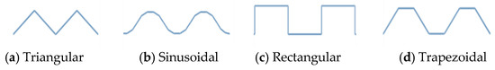
Figure 1.
Topologies commonly used in corrugated core sandwich panels. (a) Triangular; (b) Sinusoidal; (c) Rectangular; (d) Trapezoidal.
Rubino, et al. [40], compare the dynamic performance of the triangular/V-shape corrugated core panels with monolithic plates by measuring permanent transverse deflection of those fully-clamped structures. The sandwich panels outperformed monolithic plates of equal mass and the plastic strain of the sandwich panel’s frontal face exceeded that of monolithic plates [40]. Three-dimensional fully coupled simulation was conducted by Zhang, et al. [41], to investigate in detail the performance of V-shape sandwich panels when subjected to close-range air blast. The numerical study showed that the failure/deformation modes of the tested panels are mainly linked to stand-off distance. It was also found that the core configuration affects the global deflection with negligible influence on the peak reflected pressure [41]. Rejab and Cantwell [42] show detailed experimental and numerical compression response of aluminum triangular corrugated-core sandwich panels. The initial failure mode was buckling of the cell walls, followed by fracture of the cell walls, then, localized delamination and finally debonding between the layers [42].
Metallic Sinusoidal corrugated core sandwich panels with polymeric foam filling were developed by Yazici, et al. [43]. Both the experimental and the numerical simulations revealed that foam filling usually improved sandwich panel blast resistivity, with reducing deflections at the rear and frontal faces by >50%. In addition, for simply-supported panels, the benefits of foam infill were more prominent than the encastred edge panels [43]. The use of arc-shaped layers arranged with uniform and nonuniform thicknesses (graded core) was investigated in another study [44]. The Split-Hopkinson bar and shock tube experiments (supported by FE model) showed that arc-shaped core layers with nonuniform thicknesses (graded) outperform those with uniform thicknesses [44,45].
Blast performance of trapezoidal corrugated cores, made of 304 stainless steel material, was investigated by Zhang, et al. [36] through a series of air blast experiments. Results revealed that the influence of the frontal sheet’s thickness on the panel’s overall deflection is greater than that of the rear sheet. Moreover, increasing the core plate thickness and corrugation angle revealed better blast performance [36]. Wijaya and Kim [46], compare the blast response of unstiffened and stiffened trapezoidal corrugated core panels. The study concludes that unstiffened panels produce localized buckling and a larger permanent deformation than the stiffened cores [46]. An experimental shock tube study [47], show the blast response of trapezoidal corrugated panel and investigate the influence of its connection details. The results highlight the conservative nature of the blast wall design guidelines, which limit the deflections to 1/40 of the blast wall height, leading to a more economical design [47]. In Liang, et al. [48], an efficient method was developed which combines the Backtrack Programming Method (BPM) with the Feasible Direction Method (FDM) to look at the optimum design of trapezoidal cores under blast pressures. Failure behavior constraints and structure buckling were taken into considerations in the optimum design. The study can be considered as a valuable guide for the design of corrugated core sandwich panels [48]. In Li, et al. [49], a ballistic pendulum system and FE simulations were used to examine the air blast response of trapezoidal corrugated sandwich panels. The structures’ failure modes, history of deformation, and absorption of energy were analyzed. Parametric studies demonstrate that the face sheets’ residual deflections may be minimized by increasing the yield stress, thickness, and contact area between the face sheet and core [49]. Kılıçaslan, et al. [50] propose adding interlayer sheets between multilayer trapezoidal aluminum corrugated core sandwich structures. The study shows that multilayering can reduce buckling stress and can increase densification strain of the corrugated layers. The addition of interlayer sheets led to a progressive and homogenous deformation of the individual layers at the cost of lower specific energy absorption capability [50,51].
Rong, et al. [52], performed a thorough comparative study of all geometric configurations mentioned earlier. The main aim was to check the effect of geometric topologies (Figure 1) on the behavior of sandwich panels, when subjected to small or high energy impact. Results show that sinusoidal core sandwich panels have lower compression stiffness, lower ultimate strengths, and the least energy absorption. Major debonding observed in sandwich panels with triangular and sinusoidal cores because of the small bonding/welding area. The rectangular and trapezoidal cores absorbed more energy than the other structures. However, Rong, et al. [52] mention that the forming process of rectangular core can be demanding, as the stamping die is difficult to separate from the core during fabrication. The study concludes that, “trapezoidal corrugated core is an excellent structure with balanced performance for engineering application” [52].
Analytical solutions were also proposed [53,54,55] for different geometrical configurations. As an example, in Bartolozzi, et al. [56], a general analytical formulation is proposed to model every core-geometry, overcoming the main limitation of existing analytical formulations (availability of analytical formulations for specific geometrical configurations). Moreover, researchers in this field recommend using graded layers (nonuniform thicknesses) that allows energy absorption for different impact/blast loading scenarios [9,45]. Li, et al. [57], moreover, praise graded-core usage and state that, “graded sandwich panels, especially for relative density descending core arrangement, would display a better blast resistance than the ungraded ones”. Therefore, in this research, a graded system will be considered.
To the authors’ knowledge, the impact/blast behavior of sandwich panels with welded/bolted/riveted corrugated layers has been well covered in literature. The connections between the core layers give integrity to the whole panel to work as one unit. However, the plastic deformation of a single layer may get affected by the adjacent layers; hence, reducing plastic dissipation energy. Therefore, this study proposes a new panel configuration with “unconnected” graded corrugated layers encased in a steel frame. The study compares numerically the air blast response (reaction forces, peak deformations, and plastic dissipation energy) of aluminum sandwich panels with four different unconnected layer topologies, namely, trapezoidal, triangular, sinusoidal, and rectangular. The directions of the corrugated layers will be cross-arranged (0°/90°), as it gives better energy absorption than the regular-arranged [58]. The most efficient topology is then thoroughly investigated for other blast loading scenarios. This is mainly to achieve a unique graded sandwich panel as a multipurpose sacrificial protective structure. The new unconnected/nonwelded configuration proposed here, may also simplify the production process and may lead to a more cost-effective sandwich panels.
2. Geometrical and Material Properties
As mentioned earlier, this study proposes a new panel configuration with “unconnected” corrugated layers encased in a steel frame. The comparative performance-based study is for four different topologies, namely, trapezoidal, triangular, sinusoidal, and rectangular. The geometry and dimensions of the four topologies are shown in Figure 1. To achieve a valid energy dissipation comparison between the topologies, the mass should be the same. Therefore, all topologies were designed so that the profile total length (before corrugation) is unified (386 mm) with a uniform aluminium plate thickness of 1 mm. Therefore, as shown in Figure 2a–c, the length of the trapezoidal, triangular and sinusoidal topologies (after corrugation) is 320 mm, while the rectangular topology (Figure 2d) has a 310 mm length. It is also important to highlight that all 4 topologies has the same height of 20 mm (21 mm with the 1 mm plate thickness) and extrusion depth of 320 mm. Moreover, all four topologies have the same aluminium grade (AL6063-T4). Hence, the mass of one layer of any topology would be equal (0.34 kg).
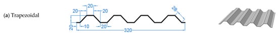
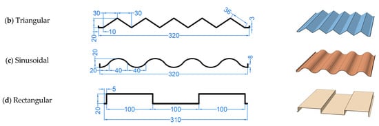
Figure 2.
Cross-sectional dimensions (mm) and 3D views of the topologies covered in this paper. (a) Trapezoidal; (b) Triangular; (c) Sinusoidal; (d) Rectangular.
The AL6063-T4 is a low strength aluminum (yield point of 90 MPa) that is commonly used for door, windows, and furniture. It has lower strength, high ductility, and less rate dependency than other high strength grades (such as 7075-T6). The selection of this grade (AL6063-T4) was based on the conclusions of Al-Rifaie and Sumelka [9] that compared the energy absorption of three cores of different aluminum grades. The study highlights that the use of relatively weak grade, such as AL6063-T4, allows more deformation in the core, greater energy absorption, and lower reaction forces in the supports [9]. Further details on the material model of AL6063-T4 will be shown in Section 4.
Six layers were implemented for each corrugated core topology. Table 1 shows the side and 3D views of the six layers per core that has a total thickness of 131 mm (including the 1 mm material thickness and 1 mm gap between the layers). As mentioned earlier, the directions of the corrugated layers are cross-arranged (0°/90°). The last column of Table 1 illustrates how the corrugated core is positioned in a specifically designed steel frame that will be described below.

Table 1.
Side and 3D views of the six corrugated layers composing the aluminium cores of different topologies, positioned in a steel frame. (a) Trapezoidal; (b) Triangular; (c) Sinusoidal; (d) Rectangular.
A steel frame was required to hold the corrugated core of the sandwich panel in place before and after blast pressure. The “easy to build” steel frame proposed here substitute the standard known sandwich panel configuration composed of (frontal plate, corrugated core, and back steel plate) that are all laser welded to keep them integrated together. The frontal and rear views of the steel frame are shown in Figure 3. The steel frame was first designed as a cuboid with one frontal opening. Then, analysis revealed that the four sides could also be open to reduce its mass and material cost. The overall dimensions of the steel frame are 330 × 330 × 150 mm, with a frontal clear opening of 300 × 300 mm, allowing blast pressure to impact the corrugated core (Figure 3a). The rear plate was strengthened with extra stiffeners of 16 mm depth (Figure 3b). This was to reduce certain rear plate deflections due to the crushing impact of the corrugated core. All the components of the steel frame have a unified material thickness of 2 mm. The total mass of the steel frame is 4 kg. As shown in Figure 3a and Table 1, the inner space of the steel frame (330 × 330 × 134 mm) accommodates the core (320 × 320 × 131 mm) with a few millimetres gap in each side. This is to keep the layers free to deform/move within the frame’s space without connection neither between the layers, not between the layers and the frame. Weldox E steel grade has been used for the steel frame because of its ductility and high strength. Further information on Weldox E Steel material model will be given in Section 4.
Figure 3.
The 3D views of the steel frame that holds the corrugated core of the sandwich panel. (a) Frontal side; (b) Rear side.
3. Blast Loading
The new sandwich panel configuration proposed in this study, is supposed to work as a sacrificial protective structure that can absorb high impulsive blast loading generated from accidental or intentional explosion. As known, angle of incident, mass of explosive material (M), and stand-off distance (R), are the principal factors to examine. Peak reflected overpressure can be achieved when the angle of incident is equal to zero (the angle between the wave propagation vector from the explosive centroid towards the target and the outward normal of the reflecting surface) [59,60]. Therefore, the angle of incident is assumed to be 0° in this study. In terms of the mass (M) of the Improvised Explosive Device IED (the 2nd factor), the US Department of Homeland Security, in FEMA report [61], provide a range for it, in TNT equivalency. The range is dependent on the transport form, which may be luggage, a car, or a van with a maximum potential carrying weight of 45 kg, 200 kg or 2000 kg, respectively. The value of the last factor, stand-off distance (R), should be more than the longest dimension of the target, to prevent localized effect and to receive a relatively uniform blast pressure. Yuen, et al. [62], mention that, “when the stand-off distance exceeds the largest plate dimension, loading could be considered to be uniform”. Moreover, the following points were assumed in this research:
- The sandwich panel is outside fireball of explosion with no afterburning effect. Hence, it is possible to ignore the interaction with the gases created.
- The blast occurs at sea level (the altitude of the location affects the atmospheric pressure, which is an important factor for blast wave propagation).
- Additional loading from fragmentation is excluded (for more details, refer to [63,64,65,66]).
In this paper, five blast intensities denoted here as BI-1 to BI-5, are taken into consideration. Table 2 lists the five blast intensities, the chosen M-R combination in this study and their equivalent real-life M-R combinations. The mass is in kg of TNT or its equivalent while the stand-off distance R is in m. A scaled distance, Z in can link the mass M to the standoff distance R as follow:
Table 2.
The five blast intensities considered in this study, their scaled distances Z, and equivalent real-life M-R combinations (Mass is in Kg of TNT or its equivalent, stand-off distance R is in m). The highlighted column represents the considered M-R combination in this study.
The selected M-R combinations in this paper are 0.1–0.5 kg of TNT at R = 0.5 giving scaled distance Z of 1.08–0.68 . The relatively small mass selected here makes future experimental testing easier to accomplish. The selected M-R combination represents possible person-borne TNT, which is equivalent to a luggage, car, or van—borne TNT with bigger stand-off distances (Table 2). For example, the peak reflected over-pressure of blast intensity BI-5 (Z = 0.63), can be the same for (M = 0.5 kg at R = 0.5 m) and (M = 2000 kg van at R = 7.90 m), providing that there is no reflection/afterburning/debris. However, the detonation energy released and the pressure-time history of those different M-R combinations may vary. It is important to mention that all the M-R combination in Table 2 have scaled distances Z more than the minimum scaled distance of 0.4 required to avoid close-range detonations [67,68].
Using ConWep, a Conventional Weapons effects calculation built-in tool in Abaqus, the “peak reflected overpressure” and the “reflected impulse” time histories of the five blast intensities were calculated (as presented in Figure 4). The peak reflected over-pressure values are 3.83, 7.25, 11.02, 13.29, and 15.86 MPa for BI-1 to BI-5, respectively. The arrival time for the frontal shock wave is fluctuating about 0.2 ms (Figure 4a). The peak reflected impulse values range from 0.29 for BI-1 to 1.2 for BI-5. Figure 5 shows ConWep peak reflected overpressure of the blast intensity BI-5 on the trapezoidal sandwich panel at certain time frames.
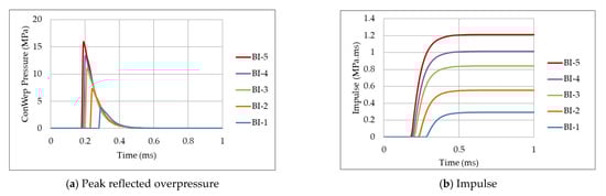
Figure 4.
ConWep “peak reflected overpressure” and “reflected impulse” time histories of the selected M-R combinations in this paper (0.1–0.5 kg of TNT at R = 0.5, listed in Table 2). (a) Peak reflected overpressure; (b) Impulse.
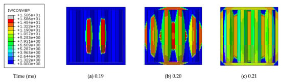
Figure 5.
Distribution and values of ConWep peak reflected overpressure on the trapezoidal-core sandwich panel, when subjected to blast intensity BI-5. (a) at 0.19 ms; (b) at 0.20 ms; (c) at 0.21 ms.
4. Numerical Model
Numerical modelling and FE codes are cost-effective tools used widely in the field of blast protective design [69,70]. Therefore, the new sandwich panel configuration proposed in this study was modelled by Abaqus (Version 2019, Dassault Systèmes, Vélizy-Villacoublay Cedex, France) and analysed by its explicit numerical solver. The steel frame and the aluminium corrugated core were simulated using 3D deformable shell elements (using five points of integration within its thickness). Two homogeneous isotropic sections were defined for both of them.
An elasto-plastic material model was used with Johnson–Cook strain hardening and damage initiation. Johnson–Cook material model is a constitutive model that can replicate the material plastic behaviour at high temperatures and high strain rates. The yield stress can be described, in Equation (2), with taking into account the thermal softening effects and the strain rate hardening [71,72,73,74]. The dimensionless temperature parameter is defined in Equation (3).
where, is plastic strain, is reference plastic strain rate, is plastic strain rate, T is current material temperature, is transition/room temperature and is melting point of the material. The material parameters measured at or below are A (yield stress), B (pre-exponential factor), C (strain rate factor), n (work-hardening exponent), and m (thermal-softening exponent).
Moreover, Abaqus provides built-in Johnson–Cook dynamic failure model [75]. When the damage parameter ω is more than 1, failure is assumed to occur. The damage parameter ω is:
where, is plastic strain at failure, is an increment of plastic strain and the summation is conducted for all increments of the analysis. The plastic strain at failure depends on pressure to Mises stress ratio , nondimensional plastic strain rate , and dimensionless temperature parameter . Hence, the strain at failure can be defined as follow:
where are the failure parameters. All material parameters for the J–C material model are listed in Table 3. The material parameters are based on Børvik, et al. [76] for Weldox 460E Steel and ASM Specification Aerospace Metals [77] for AL6063-T4 aluminium. The references include not only mechanical properties, but also chemical composition of those materials.
Table 3.
Material parameters for Weldox E Steel [76] and AL6063-T4 aluminium [77] used for the frame and the corrugated core, respectively.
The frame and the corrugated core were numerically modelled in such a way that the length of the sandwich panel is parallel to -axis, the height is parallel to -axis and the blast pressure and relative deformations follow -axis, Figure 3a. A nonlinear dynamic explicit step was implemented that have a total time of 0.01 s (10 ms). To add the effect of heat generated from plastic strains, the “Adiabatic heating effects” were also included, assuming inelastic heat fraction .
A general contact (explicit) was also assigned for the whole assembly, including tangential and normal contact options. A “penalty” friction formulation was selected for the tangential behaviour with coefficient of friction = 0.3 while a “hard” contact was chosen for the normal behaviour. As discussed earlier in Section 3, ConWep was used for the blast loading with “air blast” option.
In terms of boundary conditions (BC), the proposed sandwich panel can be attached to the structure (required to be protected) in different ways. As shown in Figure 3b, the stiffeners on the rear side of the steel frame can be all connected to the structure, or only the external perimeter/edges or only the corners. The 3rd option was chosen here, as it is the most critical in terms of expected deformations/plastic strain in the sandwich panel. The four nodal BC at the corners (restraining the Z-direction) provide concentrated nodal reactions forces. All other translational and rotational degrees of freedom are left free.
The selected mesh type was a four node doubly curved shell (S4 elements). As widely recognised, a key factor in numerical simulations is the computational cost. Hence, the less expensive model with acceptable accuracy must be defined at early stages [78,79]. Therefore, a thorough analysis of mesh size was performed based on peak reaction forces and plastic dissipation energy. The finite element size was varied from 10 mm, 5 mm, and 2.5 mm (Figure 6).
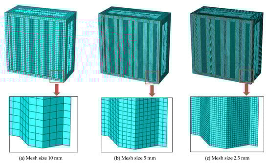
Figure 6.
The trapezoidal sandwich panel with three different mesh/element sizes (a) 10 mm, (b) 5 mm, and (c) 2.5 mm.
Mesh analysis revealed that reaction force and plastic dissipation energy for mesh size 2.5 mm and 5 mm are approximately coincident (<5% difference), as shown in Figure 7 and Figure 8 and in Table 4. However, results for 10 mm mesh size are deviated with more noticed difference of 14% (in Plastic Dissipation Energy (PDE)) and 5.3% (in Reaction Force (RFz)). So, the 5 mm mesh size was chosen for further simulations of the proposed sandwich panel, as it is the less expensive model with acceptable accuracy.
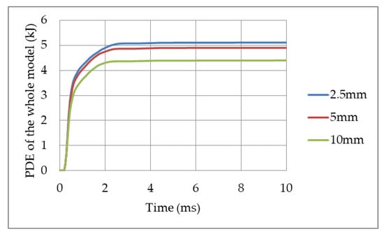
Figure 7.
Variation of the Plastic Dissipation Energy (PDE) of the whole model with respect to mesh size 2.5 mm, 5 mm, and 10 mm, for the trapezoidal sandwich panel subjected to 0.5 kg of TNT at R = 0.5 m (BI-5).
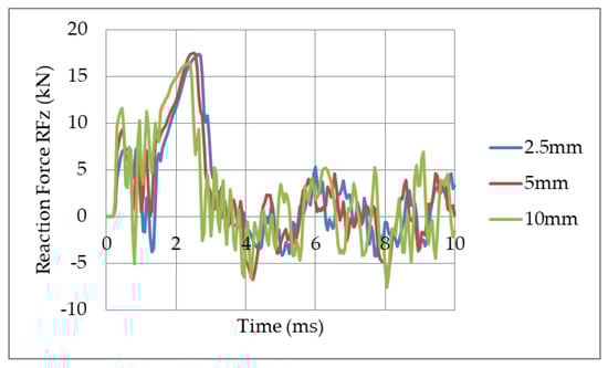
Figure 8.
Variation of Reaction Force (RFz) in a single support with respect to mesh size 2.5 mm, 5 mm and 10 mm, for the trapezoidal sandwich panel subjected to 0.5 kg of TNT at R = 0.5 m (BI-5).
Table 4.
The average difference in percentage (%) of a specific mesh size in relation to mesh size 2.5 mm.
5. Panel Response-Comparative Study
This section aims to find the most efficient topology, namely, trapezoidal, triangular, sinusoidal, or rectangular in terms of peak deformations, reaction forces, and plastic dissipation energy. The core, at this stage, was nongraded, with 1 mm of plate thickness for all corrugated layers. The mesh size was selected as 5 mm (Section 4) and the panels were subjected to 0.5 kg of TNT at R = 0.5 m (BI-5 of Table 2).
5.1. Deformations
As known, there are three stages in the deformation/crushworthiness of corrugated cores, namely, elastic stage, plateau stage, and densification stage [58]. These stages can be seen within few milliseconds or even part of milliseconds. The elastic and densification stages are short compared to the plateau stage, where plastic deformations mainly occur. The deformation of the corrugated cores per time, for the four topologies studied here, is shown in Table 5, for selected time steps (0, 0.5, 1, 1.5, and 2 ms). Moreover, Table 5 presents the 3D view of the panel with peak deformations. The last column shows the peak deformation value (the max. observed value of deformation between the 0–10 ms time of analysis) and core compressive strain (peak deformation divided by the total core thickness of 131 mm). It is important to highlight here that the last two columns of Table 5 are not necessarily at time 2 ms as this vary based on topology. The peak deformation value was not measured at a predefined specific loacation of the core, and was found based on the Abaqus/Explicit output of a specific corrugation topology (mainly in the frontal layer of the core). Looking at time 0.5 ms (3rd column of Table 5), all topologies reveal progressive collapse (layer by layer). The frontal two layers were already compressed by that time and the other four are still approximately nondeformed. At time of 1 ms, two additional layers were deformed and the global behavior of the cores start to differ. At time 2 ms, where peak deformations were almost achieved, some of the topologies reached full densification while others did not.
Table 5.
Comparison between deformations (in mm) and compressive strains () of the four topologies when subjected to 0.5 kg of TNT at R = 0.5 m (BI-5).
It appears that the sinusoidal topology (last row of Table 5) has more local deformations in each layer in addition to concave shape to the whole core. A full densification was also perceived with 111 mm peak deformation. This account for ~85% of the total core thickness (which is 131 mm). This extreme response can be linked to the low out-of-plane stiffness of arc-shaped topology. The results agree with the conclusions of Rong, et al. [52] that “arc-shaped cores have lower compression stiffnesses”. In terms of rectangular topology, large local buckling can be noticed that layers even penetrate each other. At time 2 ms, peak deformations of 112 mm can be seen, which is the highest compared to other topologies. The reason is that, in rectangular topology, the exposed surface area that is perpendicular to blast wave propagation is bigger (the area with angle of incident = 0°). The trapezoidal and triangular topologies showed more uniform progressive collapse with no concave or extreme global or local buckling. The peak deformations () were 101 mm and 94 mm, with compressive strain () of 0.77 and 0.72, respectively. They both did not reach full densification, i.e., no full impact is expected on the frame.
The deformation time-history of the frame’s rear center point of the four topologies is presented in Figure 9. The deformation of the steel frame is also critical as the frame may be fixed to the target/building elevation in different ways. The trapezoidal-core revealed the least deformation of max. 9 mm in the frame’s rear center point compared to those when using other topologies. The rectangular-core had the highest deformation (~21 mm).
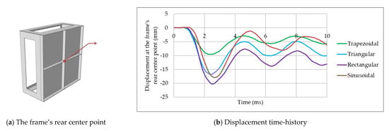
Figure 9.
The effect of corrugation shape/topology on the displacement time-history of the frame’s rear center point subjected to 0.5 kg of TNT at R = 0.5 m (BI-5). (a) The frame’s rear center point; (b) Displacement time-history.
5.2. Peak Nodal Reaction Forces
The reaction forces, in general, are one of the vital parameters to be assessed when using sandwich panels. Boundary conditions/supports transmit the unabsorbed blast energy to the protected target that the sacrificial panel is attached to. The more energy absorbed by the core, the less reaction forces are expected. Figure 10 shows the effect of corrugation shape/topology on the nodal reaction force time-history (in one support) when the sandwich panel is subjected to 0.5 kg of TNT at R = 0.5 m (BI-5). A simple solid plate was initially modeled and the corresponding reaction forces per time to the same blast intensity (BI-5) was recorded. Results showed that RFz of a solid plate goes as high as 44 kN compared to ~19 kN average peak reaction force when using sandwich panels as energy absorbers (Figure 10). In other words, using those proposed sandwich panels, can eliminate 57% of the reaction forces, leading to less loading on the target required to be protected. These results agree with the findings of [60], where 49% of peak reaction forces were diminished.
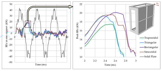
Figure 10.
The effect of corrugation shape/topology on the nodal reaction force time-history (in one support) when the sandwich panel is subjected to 0.5 kg of TNT at R = 0.5 m (BI-5).
The high compressive strains of the rectangular and sinusoidal topologies (Table 5) led to higher nodal reaction forces (with peak RFz = ~20 kN). As expected, the trapezoidal topology showed the least (with peak RFz = 17.5 kN). In other words, with choosing the correct corrugation shape/topology, 13% of reaction forces may be eliminated (Trapezoidal topology compared to rectangular one).
5.3. Energy Dissipation
As the aim of this study is to design a new efficient blast-absorbing sacrificial sandwich panel, the plastic dissipation energy (PDE) of the whole numerical model (frame + core), is the most important factor to assess. The comparison is valid as all compared topologies have the same mass and material properties. Figure 11 shows the effect of corrugation shape/topology on the plastic dissipation energy of the sandwich panel, when subjected to 0.5 kg of TNT at R = 0.5 m (BI-5). It shows that the PDE of trapezoidal core was the highest (4.90 kJ) compared to 4.45 kJ for the sinusoidal core. Keeping the sinusoidal PDE as a benchmark, the rectangular, triangular, and trapezoidal topologies had 2.7%, 7.1%, and 10% more PDE than the sinusoidal, respectively. The number of bends/corrugations in a single trapezoidal or triangular corrugated layer is more than that of rectangular and sinusoidal layer in addition to the stiffness differences. Hence, under impact, more energy can be dissipated using trapezoidal topology. Rong, et al. [52], provide similar conclusions that, “Sandwich panels with sinusoidal and arc-shaped cores caused lower energy absorption due to lower out-of-plane stiffness”. The high PDE of trapezoidal core has dropped the kinetic energy (KE) of the numerical model faster than other topologies. Figure 12 shows the effect of corrugation topology on the kinetic energy of the sandwich panel, when subjected to 0.5 kg of TNT at R = 0.5 m (BI-5). The energy components (PDE and KE) were achieved using Abaqus built-in history output requests.
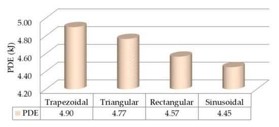
Figure 11.
The effect of corrugation shape/topology on the plastic dissipation energy of the sandwich panel, when subjected to 0.5 kg of TNT at R = 0.5 m (BI-5).
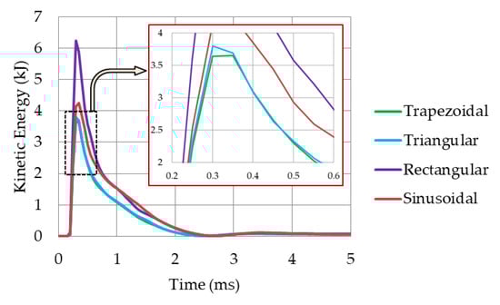
Figure 12.
The effect of corrugation shape/topology on the kinetic energy of the sandwich panel, when subjected to 0.5 kg of TNT at R = 0.5 m (BI-5).
In short, results clearly highlight that the trapezoidal topology is the most efficient option compared to other topologies, with uniform compression, lower reaction forces, and higher PDE. Therefore, the trapezoidal topology was selected for further analyses, as shown in the following section.
6. The ‘Graded’ Sandwich Panel
Based on literature review in Section 1, it was concluded that, “little work has been done on the blast responses of sandwich plates consisting of graded corrugated cores” [44]. Moreover, core layers with nonuniform thicknesses (graded) outperform those with uniform thicknesses (nongraded). The main reason of using graded core is to account for different loading scenarios. For example, the most efficient trapezoidal topology (selected in Section 5) was successful in absorbing a blast intensity BI-5 (Table 2) or its equivalent. However, the same core would be too stiff to deform/absorb other lower blast intensities (e.g., BI-1 or BI-2). Hence, the uniform thickness (1 mm) of the six trapezoidal layers had to be altered to three different thicknesses (one thickness for each couple of layers). Different combinations were numerically studied, such as (0.3, 0.6, 0.9 mm), (0.4, 0.8, 1.2 mm), and (0.5, 1.0, 1.5 mm). Based on the performance of the mentioned stepwise combinations to all five blast intensities BI-1 to BI-5, the (0.4, 0.8, 1.2 mm) combination was selected for the graded trapezoidal core (as shown in Figure 13).
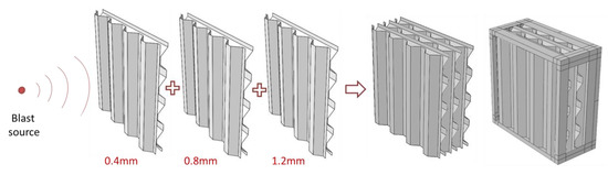
Figure 13.
The composition of the graded trapezoidal core.
To check how effective is the graded trapezoidal core compared to the nongraded (selected in Section 5), the comparison between peak deformations/compressive strain is shown in Table 6 for all blast intensities (BI-1 to BI-5). It can be noticed that peak deformations, and, hence, compressive strains, were generally higher when using a graded core. For instance, the total compressive strain was 65% when using a graded core compared to only 23% of the nongraded core (for BI-1). This higher plastic deformation can positively increase the PDE and, hence, the efficiency of the sandwich panel. Figure 14 shows the peak deformations of the graded sandwich panel when subjected to 0.5 kg of TNT at R = 0.5 m (BI-5). Only the frontal layer was severely damaged while 2nd–5th layers were plastically deformed and last layer revealed minor deformations. The compressive strain of the whole core was 88%, the highest among others (Table 6). The steel frame stays in elastic range, except near the supporting corners, where slight nonelastic deformations were observed.
Table 6.
Comparison between deformations (in mm) and compressive strains () of the nongraded and graded trapezoidal cores when subjected to blast intensities BI-1 to BI-5.
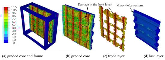
Figure 14.
Peak deformations (mm) of the graded sandwich panel showing frontal layer damage and last layer minor deformations, when subjected to 0.5 kg of TNT at R = 0.5 m (BI-5). (a) graded core and frame; (b) graded core; (c) front layer; (d) last layer.
Figure 15 shows the comparison between the PDE of the nongraded (red) and graded (blue) trapezoidal cores when subjected to blast intensities BI-1 to BI-5. The gap between the ‘red’ and ‘blue’ bars is sharply increasing revealing the superior PDE of graded core. It is worth highlighting that the PDE is not the only, but the dominant energy component. Figure 16 shows the energy components of the graded trapezoidal core, when subjected to 0.5 kg of TNT at R = 0.5 m (BI-5). Results show that the internal energy (IE) in the graded trapezoidal core is composed of PDE, frictional dissipation energy (FDE) and very small damage dissipation energy (DDE) due to noticeable damage in the frontal layer. As mentioned earlier, the energy components (IE, PDE, FDE, and DDE) were recorded based on Abaqus built-in history output requests for the whole numerical model. It is worth mentioning that the final numerical model has a size of 40,908 finite elements and 252,972 degrees of freedom.
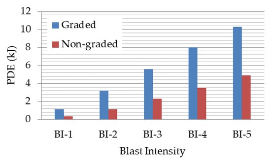
Figure 15.
Comparison between the plastic dissipation energy (PDE) of the nongraded and graded trapezoidal cores when subjected to blast intensities BI-1 to BI-5.
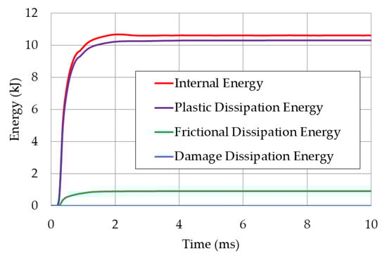
Figure 16.
Energy components of the graded trapezoidal core, when subjected to 0.5 kg of TNT at R = 0.5 m (BI-5).
The superior performance of the proposed sandwich panel with unconnected graded layers (Figure 13) can be considered as a novel alternative to the costly connected/laser-welded corrugated layers. The sacrificial system presented in this research can be used to protect various blast-vulnerable structures, ranging from multistorey buildings to armoured vehicles.
7. Conclusions
The aim of this numerical study was to develop a unique, easy-to-build, non-expensive, graded sandwich panel that can be used as a multipurpose sacrificial protective structure against a wide range of blast threats. The proposed sandwich panel consist of “unconnected” aluminium corrugated layers encased in a steel frame. The directions of the corrugated layers were cross-arranged (0°/90°) based on literature recommendations. The numerical study was conducted using Abaqus/Explicit solver and consists of two main steps:
Step 1: Conducting a comparative study of the air blast response (reaction forces, peak deformations, and plastic dissipation energy) of four different unconnected nongraded layer topologies, namely, trapezoidal, triangular, sinusoidal, and rectangular topologies, when subjected to one blast intensity (BI-5, Table 2):
Results showed that the trapezoidal topology is the most efficient option compared to other topologies, with uniform progressive collapse, lower reaction forces, and higher PDE. The peak deformations were 101 mm, with compressive strain () of 77%. The trapezoidal-core also revealed the least deformation of max. 9 mm in the frame’s rear center point compared to those when using other topologies. In terms of peak nodal reaction forces, up to 13% of reaction forces can be reduced when using trapezoidal topology. Keeping the sinusoidal PDE as a benchmark, the rectangular, triangular, and trapezoidal topologies had 2.7%, 7.1%, and 10% more PDE than the sinusoidal, respectively. Based on those outcomes, the trapezoidal topology clearly outperformed other topologies, and, hence, was selected.
Step 2: Implementing the most efficient selected topology (in step 1) for developing a ‘graded’ sandwich panel that can absorb a wide range of blast intensities (BI-1 to BI-5, Table 2):
Based on the performance of the three stepwise thickness combinations to all five blast intensities BI-1 to BI-5, the (0.4, 0.8, 1.2 mm) combination was selected for the graded trapezoidal core (Figure 13). Peak deformations, and, hence, compressive strains, increased dramatically when using the graded core. When subjected to high blast intensity (BI-5), the frontal layer was severely damaged and last layer revealed minor deformations with compressive strain of 88%. Moreover, PDE of graded core was more than double that of the nongraded core, showing superior blast absorption capacity.
The sacrificial sandwich panel, with unconnected trapezoidal core layers presented here, can be considered as a general purpose, easy-to-build, non-expensive protective system against a wide range of far-field blast intensities (Table 2). The solution can protect buildings’ frontal façade, bridge piers, armoured vehicles, blast doors, and other sensitive structures. Manufacturing and field-testing of the proposed sandwich panel is the authors’ future interest.
Author Contributions
Conceptualization, H.A.-R.; methodology, H.A.-R.; software, H.A.-R.; validation, W.S. and P.W.S.; formal analysis, H.A.-R.; investigation, H.A.-R.; resources, H.A.-R.; data curation, H.A.-R.; writing—original draft preparation, H.A.-R.; writing—review and editing, R.S., T.G. and M.M.; visualization, H.A.-R.; supervision, P.W.S. and W.S.; project administration, P.W.S.; funding acquisition, P.W.S.”, please turn to the CRediT taxonomy for the term explanation. All authors have read and agreed to the published version of the manuscript.
Funding
This research was funded by the National Centre for Research and Development, Poland, under the grant DOB-BIO10/01/02/2019 within the Defence and Security Programme.
Institutional Review Board Statement
Not applicable.
Informed Consent Statement
Not applicable.
Data Availability Statement
Data is contained within the article.
Conflicts of Interest
The authors declare no conflict of interest.
References
- Miller, E.; LaFree, G.; Dugan, L. Global Terrorism Database (GTD). Available online: https://start.umd.edu/research-projects/global-terrorism-database-gtd (accessed on 5 May 2020).
- Mazek, S.A. Performance of Sandwich Structure Strengthened by Pyramid Cover under Blast Effect. Struct. Eng. Mech. 2014, 50, 471–486. [Google Scholar] [CrossRef]
- Lotfi, S.; Zahrai, S.M. Blast Behavior of Steel Infill Panels with Various Thickness and Stiffener Arrangement. Struct. Eng. Mech. 2018, 65, 587–600. [Google Scholar]
- Al-Rifaie, H.; Sumelka, W. Numerical Analysis of Reaction Forces in Blast Resistant Gates. Struct. Eng. Mech. 2017, 63, 347–359. [Google Scholar]
- Draganić, H.; Gazić, G.; Varevac, D. Experimental Investigation of Design and Retrofit Methods for Blast Load Mitigation–A State-of-the-Art Review. Eng. Struct. 2019, 190, 189–209. [Google Scholar] [CrossRef]
- Sielicki, P.; Lodygowski, T.; Al-Rifaie, H.; Sumelka, W. Designing of Blast Resistant Lightweight Elevation System—Numerical Study. Procedia Eng. 2017, 172, 991–998. [Google Scholar] [CrossRef]
- Alberdi, R.; Przywara, J.; Khandelwal, K. Performance Evaluation of Sandwich Panel Systems for Blast Mitigation. Eng. Struct. 2013, 56, 2119–2130. [Google Scholar] [CrossRef]
- Al-Rifaie, H. Application of Passive Damping Systems in Blast Resistant Gates, 1st ed.; Wydawnictwo Politechniki Poznańskiej: Poznan, Poland, 2019. [Google Scholar]
- Al-Rifaie, H.; Sumelka, W. The Development of a New Shock Absorbing Uniaxial Graded Auxetic Damper (UGAD). Materials 2019, 12, 2573. [Google Scholar] [CrossRef]
- Novak, N.; Vesenjak, M.; Ren, Z. Auxetic Cellular Materials—A Review. Strojniški Vestnik–J. Mech. Eng. 2016, 62, 485–493. [Google Scholar] [CrossRef]
- Novak, N.; Starčevič, L.; Vesenjak, M.; Ren, Z. Blast Response Study of the Sandwich Composite Panels with 3D Chiral Auxetic Core. Compos. Struct. 2019, 210, 167–178. [Google Scholar] [CrossRef]
- Baranowski, P.; Małachowski, J.; Mazurkiewicz, Ł.A. Numerical and Experimental Testing of Vehicle Tyre under Impulse Loading Conditions. Int. J. Mech. Sci. 2016, 106, 346–356. [Google Scholar] [CrossRef]
- Nowak, Z.; Pęcherski, R.; Potoczek, M.; Śliwa, R.; Nowak, M. Numerical Simulations of Mechanical Properties of Alumina Foams Based on Computed Tomography. J. Mech. Mater. Struct. 2017, 12, 107–121. [Google Scholar] [CrossRef]
- Andrews, E.; Sanders, W.; Gibson, L. Compressive and Tensile Behaviour of Aluminum Foams. Mater. Sci. Eng. A 1999, 270, 113–124. [Google Scholar] [CrossRef]
- Pecherski, R.B.; Nowak, M.; Nowak, Z. Virtual Metallic Foams. Application for Dynamic Crushing Analysis. Int. J. Multiscale Comput. Eng. 2017, 15, 431–442. [Google Scholar] [CrossRef]
- Papadopoulos, D.; Konstantinidis, I.; Papanastasiou, N.; Skolianos, S.; Lefakis, H.; Tsipas, D. Mechanical Properties of Al Metal Foams. Mater. Lett. 2004, 58, 2574–2578. [Google Scholar] [CrossRef]
- Peroni, L.; Avalle, M.; Peroni, M. The Mechanical Behaviour of Aluminium Foam Structures in Different Loading Conditions. Int. J. Impact Eng. 2008, 35, 644–658. [Google Scholar] [CrossRef]
- Gibson, L.J.; Ashby, M.F. Cellular Solids: Structure and Properties; Cambridge University Press: Cambridge, UK, 1999. [Google Scholar]
- Dharmasena, K.P.; Wadley, H.N.; Xue, Z.; Hutchinson, J.W. Mechanical Response of Metallic Honeycomb Sandwich Panel Structures to High-Intensity Dynamic Loading. Int. J. Impact Eng. 2008, 35, 1063–1074. [Google Scholar] [CrossRef]
- Li, X.; Zhang, P.; Wang, Z.; Wu, G.; Zhao, L. Dynamic Behavior of Aluminum Honeycomb Sandwich Panels under Air Blast: Experiment and Numerical Analysis. Compos. Struct. 2014, 108, 1001–1008. [Google Scholar] [CrossRef]
- Rathbun, H.; Radford, D.; Xue, Z.; He, M.; Yang, J.; Deshpande, V.; Fleck, N.; Hutchinson, J.; Zok, F.; Evans, A. Performance of Metallic Honeycomb-Core Sandwich Beams under Shock Loading. Int. J. Solids Struct. 2006, 43, 1746–1763. [Google Scholar] [CrossRef]
- Hu, L.; Yu, T.X. Dynamic Crushing Strength of Hexagonal Honeycombs. Int. J. Impact Eng. 2010, 37, 467–474. [Google Scholar] [CrossRef]
- Okumura, D.; Ohno, N.; Noguchi, H. Post-buckling Analysis of Elastic Honeycombs Subject to in-Plane Biaxial Compression. Int. J. Solids Struct. 2002, 39, 3487–3503. [Google Scholar] [CrossRef]
- Zou, Z.; Reid, S.; Tan, P.; Li, S.; Harrigan, J. Dynamic Crushing of Honeycombs and Features of Shock Fronts. Int. J. Impact Eng. 2009, 36, 165–176. [Google Scholar] [CrossRef]
- Ruan, D.; Lu, G.; Wang, B.; Yu, T. In-Plane Dynamic Crushing of Honeycombs—A Finite Element Study. Int. J. Impact Eng. 2003, 28, 161–182. [Google Scholar] [CrossRef]
- Al-Rifaie, H.; Sumelka, W. Auxetic Damping Systems for Blast Vulnerable Structures. In Handbook of Damage Mechanics, 2nd ed.; Voyiadjis, G.Z., Ed.; Springer: Berlin/Heidelberg, Germany, 2020; p. 25. [Google Scholar]
- Xu, S.; Beynon, J.H.; Ruan, D.; Lu, G. Experimental Study of the Out-of-Plane Dynamic Compression of Hexagonal Honey-Combs. Compos. Struct. 2012, 94, 2326–2336. [Google Scholar] [CrossRef]
- Nia, A.A.; Sadeghi, M. The Effects of Foam Filling on Compressive Response of Hexagonal Cell Aluminum Honeycombs under Axial Loading-Experimental Study. Mater. Des. 2010, 31, 1216–1230. [Google Scholar] [CrossRef]
- Hou, X.; Deng, Z.; Zhang, K. Dynamic Crushing Strength Analysis of Auxetic Honeycombs. Acta Mech. Solida Sin. 2016, 29, 490–501. [Google Scholar] [CrossRef]
- Imbalzano, G.; Linforth, S.; Ngo, T.D.; Lee, P.V.S.; Tran, P. Blast Resistance of Auxetic and Honeycomb Sandwich Panels: Comparisons and Parametric Designs. Compos. Struct. 2018, 183, 242–261. [Google Scholar] [CrossRef]
- Alderson, A. A Triumph of Lateral Thought. Chem. Ind. 1999, 17, 384–391. [Google Scholar]
- Yang, W.; Li, Z.-M.; Shi, W.; Xie, B.-H.; Yang, M.-B. Review on Auxetic Materials. J. Mater. Sci. 2004, 39, 3269–3279. [Google Scholar] [CrossRef]
- Greaves, G.N. Poisson’s Ratio over Two Centuries: Challenging Hypotheses. Notes Rec. R. Soc. 2013, 67, 37–58. [Google Scholar] [CrossRef]
- Liu, Y.; Hu, H. A Review on Auxetic Structures and Polymeric Materials. Sci. Res. Essays 2010, 5, 1052–1063. [Google Scholar]
- Prawoto, Y. Seeing Auxetic Materials from the Mechanics Point of View: A Structural Review on the Negative Poisson’s Ratio. Comput. Mater. Sci. 2012, 58, 140–153. [Google Scholar] [CrossRef]
- Zhang, P.; Liu, J.; Cheng, Y.S.; Hou, H.; Wang, C.; Li, Y. Dynamic Response of Metallic Trapezoidal Corrugated-Core Sandwich Panels Subjected to Air Blast Loading–An Experimental Study. Mater. Des. 2015, 65, 221–230. [Google Scholar] [CrossRef]
- Wiernicki, C.J.; Liem, F.; Wood, G.D.; Furio, A.J. Structural Analysis Methods for Lightweight Metallic Corrugated Core Sandwich Panels Subjected to Blast Loads. Nav. Eng. J. 1991, 103, 192–202. [Google Scholar] [CrossRef]
- Studziński, R.; Gajewski, T.; Malendowski, M.; Sumelka, W.; Al-Rifaie, H.; Peksa, P.; Sielicki, P.W. Blast Test and Failure Mechanisms of Soft-Core Sandwich Panels for Storage Halls Applications. Materials 2021, 14, 70. [Google Scholar] [CrossRef] [PubMed]
- Studziński, R.; Pozorski, Z. Experimental and Numerical Analysis of Sandwich Panels with Hybrid Core. J. Sandw. Struct. Mater. 2016, 20, 271–286. [Google Scholar] [CrossRef]
- Rubino, V.; Deshpande, V.S.; Fleck, N. The Dynamic Response of Clamped Rectangular Y-Frame and Corrugated Core Sandwich Plates. Eur. J. Mech.—A/Solids 2009, 28, 14–24. [Google Scholar] [CrossRef]
- Zhang, P.; Cheng, Y.S.; Liu, J. Numerical Analysis of Dynamic Response of Corrugated Core Sandwich Panels Subjected to Near-Field Air Blast Loading. Shock. Vib. 2014, 2014, 1–16. [Google Scholar] [CrossRef]
- Rejab, M.R.M.; Cantwell, W.J. The Mechanical Behaviour of Corrugated-Core Sandwich Panels. Compos. Part B: Eng. 2013, 47, 267–277. [Google Scholar] [CrossRef]
- Yazici, M.; Wright, J.; Bertin, D.; Shukla, A. Experimental and Numerical Study of Foam Filled Corrugated Core Steel Sandwich Structures Subjected to Blast Loading. Compos. Struct. 2014, 110, 98–109. [Google Scholar] [CrossRef]
- Zhang, L.; Hebert, R.; Wright, J.; Shukla, A.; Kim, J.-H. Dynamic Response of Corrugated Sandwich Steel Plates with Graded Cores. Int. J. Impact Eng. 2014, 65, 185–194. [Google Scholar] [CrossRef]
- Zhang, Z.; Lei, H.; Xu, M.; Hua, J.; Li, C.; Fang, D. Out-of-Plane Compressive Performance and Energy Absorption of Multi-Layer Graded Sinusoidal Corrugated Sandwich Panels. Mater. Des. 2019, 178, 107858. [Google Scholar] [CrossRef]
- Wijaya, C.; Kim, B.-T. FE Analysis of Unstiffened and Stiffened Corrugated Panels Subjected to Blast Loading. J. Mech. Sci. Technol. 2011, 25, 3159–3164. [Google Scholar] [CrossRef]
- Schleyer, G.; Lowak, M.; Polcyn, M.; Langdon, G. Experimental Investigation of Blast Wall Panels under Shock Pressure Loading. Int. J. Impact Eng. 2007, 34, 1095–1118. [Google Scholar] [CrossRef]
- Liang, C.-C.; Yang, M.-F.; Wu, P.-W. Optimum Design of Metallic Corrugated Core Sandwich Panels Subjected to Blast Loads. Ocean Eng. 2001, 28, 825–861. [Google Scholar] [CrossRef]
- Li, X.; Wang, Z.; Zhu, F.; Wu, G.; Zhao, L. Response of Aluminium Corrugated Sandwich Panels under Air Blast Loadings: Experiment and Numerical Simulation. Int. J. Impact Eng. 2014, 65, 79–88. [Google Scholar] [CrossRef]
- Kılıçaslan, C.; Güden, M.; Odacı, İ.K.; Taşdemirci, A. Experimental and Numerical Studies on the Quasi-Static and Dynamic Crushing Responses of Multi-Layer Trapezoidal Aluminum Corrugated Sandwiches. Thin-Walled Struct. 2014, 78, 70–78. [Google Scholar] [CrossRef]
- Kılıçaslan, C.; Guden, M.; Odacı, İ.K.; Taşdemirci, A. The Impact Responses and the Finite Element Modeling of Layered Trapezoidal Corrugated Aluminum Core and Aluminum Sheet Interlayer Sandwich Structures. Mater. Des. 2013, 46, 121–133. [Google Scholar] [CrossRef]
- Rong, Y.; Liu, J.; Luo, W.; He, W. Effects of Geometric Configurations of Corrugated Cores on the Local Impact and Planar Compression of Sandwich Panels. Compos. Part B: Eng. 2018, 152, 324–335. [Google Scholar] [CrossRef]
- Winkler, M.; Kress, G. Influence of Corrugation Geometry on the Substitute Stiffness Matrix of Corrugated Laminates. Compos. Struct. 2012, 94, 2827–2833. [Google Scholar] [CrossRef]
- Shaban, M.; Alibeigloo, A. Three-Dimensional Elasticity Solution for Sandwich Panels with Corrugated Cores by Using Energy Method. Thin-Walled Struct. 2017, 119, 404–411. [Google Scholar] [CrossRef]
- Xia, Y.; Friswell, M.; Flores, E.S. Equivalent Models of Corrugated Panels. Int. J. Solids Struct. 2012, 49, 1453–1462. [Google Scholar] [CrossRef]
- Bartolozzi, G.; Baldanzini, N.; Pierini, M. Equivalent Properties for Corrugated Cores of Sandwich Structures: A General Analytical Method. Compos. Struct. 2014, 108, 736–746. [Google Scholar] [CrossRef]
- Li, S.; Li, X.; Wang, Z.; Wu, G.; Lu, G.; Zhao, L. Finite Element Analysis of Sandwich Panels with Stepwise Graded Aluminum Honeycomb Cores under Blast Loading. Compos. Part: Appl. Sci. Manuf. 2016, 80, 1–12. [Google Scholar] [CrossRef]
- Hou, S.; Shu, C.; Zhao, S.; Liu, T.; Han, X.; Li, Q. Experimental and Numerical Studies on Multi-Layered Corrugated Sandwich Panels under Crushing Loading. Compos. Struct. 2015, 126, 371–385. [Google Scholar] [CrossRef]
- Rigby, S.; Fay, S.D.; Tyas, A.; Warren, J.A.; Clarke, S.D. Angle of Incidence Effects on Far-Field Positive and Negative Phase Blast Parameters. Int. J. Prot. Struct. 2015, 6, 23–42. [Google Scholar] [CrossRef]
- Al-Rifaie, H.; Sumelka, W. Improving the Blast Resistance of Large Steel Gates—Numerical Study. Materials 2020, 13, 2121. [Google Scholar] [CrossRef]
- Chipley, M.; Lyon, W.; Smilowitz, R.; Williams, P.; Arnold, C.; Blewett, W.; Hazen, L.; Krimgold, F. Primer to Design Safe School Projects in Case of Terrorist Attacks and School Shootings. Buildings and Infrastructure, 2nd ed.; Protection Series; Department of Homeland Security: Washington, DC, USA, 2012. [Google Scholar]
- Yuen, S.C.K.; Nurick, G.; Langdon, G.; Iyer, Y. Deformation of Thin Plates Subjected to Impulsive Load: Part III – an Update 25 Years On. Int. J. Impact Eng. 2017, 107, 108–117. [Google Scholar] [CrossRef]
- Szymczyk, M.; Sumelka, W.; Łodygowski, T. Numerical Investigation on Ballistic Resistance of Aluminium Multi-Layered Panels Impacted by Improvised Projectiles. Arch. Appl. Mech. 2018, 88, 51–63. [Google Scholar] [CrossRef]
- Sielicki, P.; Ślosarczyk, A.; Szulc, D. Concrete Slab Fragmentation after Bullet Impact: An Experimental Study. Int. J. Prot. Struct. 2019, 10, 380–389. [Google Scholar] [CrossRef]
- Gajewski, T.; Sielicki, P. Experimental Study of Blast Loading behind a Building Corner. Shock. Waves 2020, 30, 385–394. [Google Scholar] [CrossRef]
- Sielicki, P.W.; Stewart, M.G.; Gajewski, T.; Malendowski, M.; Peksa, P.; Al-Rifaie, H.; Studziński, R.; Sumelka, W. Field Test and Probabilistic Analysis of Irregular Steel Debris Casualty Risks from a Person-Borne Improvised Explosive Device. Def. Technol. 2020. [Google Scholar] [CrossRef]
- Rigby, S.; Tyas, A.; Clarke, S.D.; Fay, S.D.; Reay, J.J.; Warren, J.A.; Gant, M.; Elgy, I. Observations from Preliminary Experiments on Spatial and Temporal Pressure Measurements from Near-Field Free Air Explosions. Int. J. Prot. Struct. 2015, 6, 175–190. [Google Scholar] [CrossRef]
- Shin, J.; Whittaker, A.S.; Cormie, D. TNT Equivalency for Overpressure and Impulse for Detonations of Spherical Charges of High Explosives. Int. J. Prot. Struct. 2015, 6, 567–579. [Google Scholar] [CrossRef]
- Hong, X.-W.; Li, W.; Cheng, W.; Li, W.-B.; Xu, H.-Y. Numerical Simulation of the Blast Wave of a Multilayer Composite Charge. Def. Technol. 2020, 16, 96–106. [Google Scholar] [CrossRef]
- Cullis, I.; Dunsmore, P.; Harrison, A.; Lewtas, I.; Townsley, R. Numerical Simulation of the Natural Fragmentation of Ex-plosively Loaded Thick Walled Cylinders. Def. Technol. 2014, 10, 198–210. [Google Scholar] [CrossRef]
- Johnson, G.R.; Cook, W.H. A Constitutive Model and Data for Metals Subjected to Large Strains, High Strain Rates and High Temperatures. In Proceedings of the 7th International Symposium on Ballistics, Hague, The Netherlands, 19–21 April 1983; pp. 541–547. [Google Scholar]
- Johnson, G.R.; Cook, W.H. Fracture Characteristics of Three Metals Subjected to Various Strains, Strain Rates, Temperatures and Pressures. Eng. Fract. Mech. 1985, 21, 31–48. [Google Scholar] [CrossRef]
- Grazka, M.; Janiszewski, J. Identification of Johnson-Cook Equation Constants using Finite Element Method. Eng. Trans. 2012, 60, 215–223. [Google Scholar]
- Shrot, A.; Bäker, M. Determination of Johnson–Cook Parameters from Machining Simulations. Comput. Mater. Sci. 2012, 52, 298–304. [Google Scholar] [CrossRef]
- Dassault Systèmes. Abaqus Documentation; Dassault Systemes Simulia Corporation: Johnston, RA, USA, 2016. [Google Scholar]
- Børvik, T.; Hopperstad, O.; Berstad, T.; Langseth, M. A Computational Model of Viscoplasticity and Ductile Damage for Impact and Penetration. Eur. J. Mech.—A/Solids 2001, 20, 685–712. [Google Scholar] [CrossRef]
- ASM Specification Aerospace Metals. Aluminum 6063-T4. Available online: http://asm.matweb.com (accessed on 17 June 2020).
- Wisniewski, K.; Turska, E. Improved Nine-Node Shell Element MITC9i with Reduced Distortion Sensitivity. Comput. Mech. 2017, 62, 499–523. [Google Scholar] [CrossRef]
- Wisniewski, K.; Kowalczyk, P.; Turska, E. Analytical DSA for Explicit Dynamics of Elastic-plastic Shells. Comput. Mech. 2006, 39, 761–785. [Google Scholar] [CrossRef]


Publisher’s Note: MDPI stays neutral with regard to jurisdictional claims in published maps and institutional affiliations. |
© 2021 by the authors. Licensee MDPI, Basel, Switzerland. This article is an open access article distributed under the terms and conditions of the Creative Commons Attribution (CC BY) license (http://creativecommons.org/licenses/by/4.0/).