Abstract
Positively charged (cetylpyridinium chloride), negatively charged (sodium dodecyl sulfate), and non-charged (polyethylene glycol) surfactants are used as potential foulant in reverse electrodialysis systems supplying seawater and river freshwater. Fouling tendency of the foulants to ion-exchange membranes is investigated in terms of the adsorption by electromigration, electrostatic attraction, and macromolecule interaction in reverse electrodialysis systems. According to theoretical prediction of fouling tendency, charged foulants in seawater streams could foul ion-exchange membranes significantly. However, the worst fouling behavior is observed when the charged foulants are present in river streams. As a result of zeta potential measurement, it is found that the Debye length of the charged foulants decreases due to the higher ionic strength of seawater streams and causes to lower net electrostatic effect. It finally results in less fouling tendency in reverse electrodialysis.
1. Introduction
Ion-exchange membranes (IEMs) are polymeric films to provide permselectivity to anion or cation under concentration or potential gradients. Cation-exchange membranes (CEMs) and anion-exchange membranes (AEMs) mainly allow cations and anions to transport, respectively [1,2]. They were often used to be applied for the separation of charged species in aqueous solutions such as diffusion dialysis and electrodialysis (ED) [3]. Recently, since the state-of-the-art of IEMs has been developed, they started to be used in energy conversion devices such as redox flow battery, fuel cell, water electrolysis, reverse electrodialysis (RED), and capacitive deionization [4]. Common properties of IEMs for the performance in separation and energy conversion devices are high conductivity under low water content or swelling ratio, low thickness, and low areal resistance [5]. Regarding to the durability of IEMs, the chemical and mechanical stability under normal operation conditions should be commonly taken into account for all the aforementioned applications. However, fouling resistance of IEMs or frequent anti-fouling methods such as back-washing, chemical cleaning, or vibration would be also necessary if aqueous phase feeds are supplied to the applications mentioned above.
RED is an emerging salinity gradient-based power generation technology. RED has basically the same configuration of ED, which separates two streams by alternately stacked CEMs and AEMs. To generate power from Gibbs free energy of mixing by RED, IEMs stacked in RED retard rapid electrolyte mixing between a relatively lower salt concentration solution (e.g., freshwater) and a relatively high salt concentration (e.g., natural seawater, reverse osmosis brine, hypersaline lakes, or produced water hydraulic fracturing) by providing permselective ion transports of cations and anions through CEMs and AEMs, respectively [2,6,7,8,9,10]. Recently, RED has been attracted as hydrogen production technology to convert a pair of electrode reactions on the electrodes into hydrogen as a gaseous fuel [11,12,13,14,15,16]. There are various options for the electrode reactions in RED. Traditionally, the reversible redox couple, ferri-/ferrocyanide (Fe(CN)63−/ Fe(CN)64−), has been used due to no theoretically thermodynamic potential (in a real RED system, low electrode resistance by activation overpotential) [17]. Another promising electrode reaction could be water electrolysis. Water electrolysis reactions produce hydrogen and oxygen. Hydrogen is a valuable gaseous fuel which could be used in a fuel cell or hydrogen combustion engine. Even though the electrode reactions in RED are main loss in salinity gradient power generation, the production of hydrogen through the water electrolysis electrode reactions is surplus value from RED.
As mentioned earlier, membrane fouling is a serious problem causing performance loss as well as the continuous degradation of the systems using IEMs interacting with non-charged and charged inorganic/organic matters [7,18,19,20,21,22,23,24,25,26,27,28,29]. Since freshwater (i.e., river water) and seawater from natural environment are supplied to RED systems to set up salinity gradient, the streams in RED might include various natural foulants such as colloidal, organic, scale, and/or bio-foulants, which could be negatively/positively charged or non-charged [30]. The charged foulants could foul IEMs by the adsorption by electromigration under electrical field and/or the adsorption by electrostatic force caused by affinity interaction between charged substances and IEMs matrix with charged functional groups. The non-charged foulants could be also adsorbed on the surface of IEMs by the adsorption by macromolecule interaction. In other words, positively charged or non-charged substances might foul CEMs and negatively charged or non-charged substances might foul AEMs in RED systems. It is reported that natural fresh water and seawater include all kinds of the aforementioned foulants [31,32]. Nevertheless, most of the studies on the fouling of IEMs have been intensively focused on only negatively charged foulants such as bovine albumin serum, humic acid, silica sol, and sodium dodecylbenzenesulfonate [30].
In this study, all kinds of foulants are investigated in RED. Positively charged, negatively charged, and non-charged surfactants are used as potential foulants found in freshwater and seawater. The effects of the three kinds of foulants existing in dialysate, concentrate, or both compartments on the resistance of IEMs and the performance of RED are studied in terms of the adsorption by electrostatic attraction, electromigration, and macromolecule interaction.
2. Materials and Methods
CEMs and AEMs were purchased from Fujifilm (Fujifilm Manufacturing Europe B.V.: Tilburg, Netherlands). Their detail properties are summarized in Table 1. All the membranes were conditioned in 0.513 M NaCl solution, which corresponds to the average salt concentration of seawater, for 24 h prior to use.

Table 1.
Properties of ion-exchange membranes used in reverse electrodialysis [33].
Three different substances are used in this study as foulants and summarized in Table 2. They are categorized into a negatively charged, positively charged, and non-charged group. The criterion of the selection of the surfactants was molecular weight to minimize the effect of the adsorption by macromolecule interaction between IEMs and surfactants. Thus, three surfactants were chosen in a similar molecular weight range from a bunch of surfactants. The common concentration of the three surfactants is 0.1 wt.% in a dialysate (or seawater, 0.513 M NaCl) and a concentrate (or river freshwater, 0.017 M NaCl). Zeta potential of the foulant solutions in NaCl electrolyte was measured by NanoBrook Omni (Brookhaven Instruments Corp.: Holtsville, NY, USA).
Table 2.
Summary of surfactants as foulants used in this study.
A bench-scale RED stack with twenty cell pairs (twenty one CEMs and twenty AEMs) has been used at room temperature (22 ± 2 °C) as described in the previous study [7]. The effective area of an IEM was 19.6 cm2. Polytetrafluoroethylene (PTFE) gaskets of 0.1 mm thickness were mounted between the IEMs along with mesh-type spacers of 0.1 mm thickness. A pair of 50 mm diameter Pt-coated titanium mesh electrodes (Sung Wing Technology Co.: Kowloon, Hong Kong, China) were placed at both ends of the bench-scale RED stack. The bench-scale RED stack is illustrated in Figure 1.
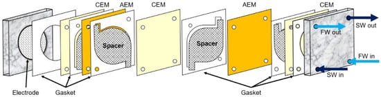
Figure 1.
Schematic diagram of a bench-scale RED system. Reprinted with permission from [7].
Two main streams and one electrode stream were supplied to the 20-cell-pair bench-scale RED system. Two synthetic feed streams were seawater with either 0.513 M NaCl as reference or 0.513 M NaCl + 0.1 wt. foulant and freshwater with 0.017 M NaCl as reference or 0.017 M NaCl + 0.1 wt.% foulant at 2.5 mL/min (or 56.6 cm/min as linear velocity). The electrode solution of 0.05 M K3[Fe(CN)6] (Junsei Chemical Co.: Tokyo, Japan), 0.05 M K4[Fe(CN)6] (Junsei Chemical Co.), and 1 M Na2SO4 (Junsei Chemical Co.) was circulated through the RED system at 50 mL/min for the minimization of the effect of water electrolysis on the performance of a RED system.
The procedure for all RED experiments consisted of the following steps: (1) The RED stack was equilibrated and activated by circulating either 0.513 M NaCl or 0.513 M NaCl + 0.1 wt. foulant as seawater and 0.017 M NaCl or 0.017 M NaCl + 0.1 wt.% foulant as river freshwater for 15 min with no connection of a power supplier. (2) Open circuit voltage (OCV) was measured for 1 min followed by the power density measurement using a linear sweep voltammetry (LSV) with a scan rate of 40 mV/s. (3) While all the feed and electrode streams were supplied to the RED system, the impedance of the bench-scale RED stack was measured. (4) The procedure from the step (1) to (3) was repeatedly carried out until 20 runs were finished.
OCV was averaged using the data recorded every three seconds for 1 min, and power was calculated from the multiplication of voltage and current obtained from LSV by a potentiostat/galvanostat with a frequency response analyzer (SP-150, Bio-Logic Science Instruments: Paris, France). The electrical impedance was also measured from 1 MHz to 1 mHz with amplitude of 10 mV. Impedance data at zero phase angle was directly used as electrical resistance.
3. Results and Discussion
Figure 2 shows the schematic diagrams of the potential membrane fouling phenomena in the presence of foulants in the concentrate stream (or river freshwater) or in the dialysate stream (or seawater) in RED. When charged foulants exist in a river freshwater or seawater stream, the foulants could be influenced by the adsorption by electromigration and electrostatic force. The non-charged foulant could be only affected by the adsorption by macromolecule interaction. If charged foulants are included in a river freshwater stream, cationic or anionic foulants move toward cathode or anode (in other words, toward the surface of the AEM or CEM in a river freshwater stream) by electromigration, but do not interact with the AEM or CEM by the adsorption by electrostatic force due to electrostatic repulsion, respectively. It means that fouling on the surface of IEMs in a river freshwater stream could be suppressed. If charged foulants are included in a seawater stream, cationic or anionic foulants move toward cathode or anode (in other words, toward the surface of the CEM or AEM in a seawater stream) by electromigration and substantially interact with the CEM or AEM by the adsorption by electrostatic force due to electrostatic attraction, respectively. It means that fouling on the surface of either CEMs or AEMs in a seawater stream could be significant. It could be expected that fouling by charged foulants could be serious when the foulants are included in a seawater stream in RED. In the case of non-charge foulants included in a seawater or a river freshwater, CEMs and/or AEMs could be commonly influenced by the adsorption by macromolecule interaction. Of course, it could be not affected to both CEMs and AEMs for non-charged foulants since the non-charged surfactants with molecular weight as low as possible have been selected.
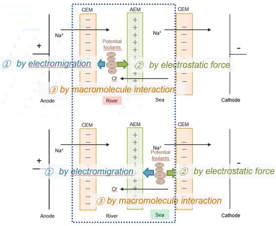
Figure 2.
Schematic diagrams of the potential IEM fouling phenomena in the presence of foulants in a river stream (top) and a seawater stream (bottom) in RED with only one cell pair (the part within the dashed square).
The possible fouling results occurred in RED systems with respect to the type of fouling phenomena, the type of foulants, and the position of including foulants are summarized in Table 3 as expected from the discussion of Figure 2.
Table 3.
Summary of the expected fouling results occurred in RED systems.
Figure 3 shows the variation of power density measured from the RED system in absence of the anionic surfactant, SDS, and in the presence of SDS in either the river freshwater stream or the seawater stream and both streams with respect to RED operation cycle. Compared to the reference which is obtained from the RED system supplying 0.513 and 0.017 M NaCl as seawater and river freshwater, the anionic foulant in the seawater stream fouled IEMs slightly due to weak adsorption to both CEM and AEM. However, the anionic foulant in the river stream fouled substantially and continuously decreased the power density with cycle. The anionic foulant in both streams represents a similar power density of the anionic foulant in the river stream. It means that most of fouling is ascribed to the anionic foulant in the river stream. The result is totally opposite to the expectation summarized in Table 3. As illustrated in Figure 4a, the hypothesis should show the worst fouling in the RED system supplying seawater containing anionic foulants due to the simultaneous fouling by the adsorption by electromigration and electrostatic attraction toward the surface of AEM in a seawater stream. The largest decrease in RED power density is, however, caused by the adsorption by electrostatic attraction between anionic foulants and AEM in a river stream as illustrated in Figure 4b.
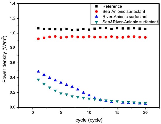
Figure 3.
Variation of power density of the RED systems with the number of operation cycles with respect to the presence of the anionic foulant (SDS) included in seawater, river, or both.
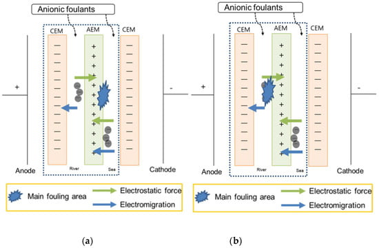
Figure 4.
Illustration of showing (a) the hypothesis and (b) the experimental result of the RED system with only one cell pair (the part within the dashed square) supplying seawater and river containing anionic foulants.
Figure 5 represents that the cationic foulant, CPC, in the seawater stream weakly fouled IEMs due to weak adsorption to both CEM and AEM. However, it shows stronger fouling than the anionic foulant since the CPC has higher molecular weight than SDS. Similar to the case of the anionic foulant, the cationic foulant in the river stream fouled IEMs significantly. The cationic foulant in both streams shows a similar variation with the cationic foulant in the river streams. The result is also opposite to the expected result in Table 3. As illustrated in Figure 6a, the hypothesis should obtain the worst fouling in the RED system supplying seawater containing cationic foulants due to the simultaneous fouling by the adsorption by electromigration and electrostatic attraction toward the surface of CEM in a seawater stream. Nevertheless, it is found that the significant decrease in RED power density results from solely the adsorption by electrostatic attraction between cationic foulants and CEM in a river stream as illustrated in Figure 6b. It is the same trend to show worse fouling for a river stream containing charged (both negative and positive) foulants than for a seawater stream containing the foulants. It is noted that the anionic foulant shows accumulated fouling behavior. On the other hand, the cationic foulant shows no accumulation of the foulant on the surface of the CEM in a river stream since the resistance of the stack exhibits constant with the number of cycle.
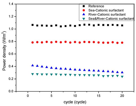
Figure 5.
Variation of power density of the RED systems with the number of operation cycles with respect to the presence of the cationic foulant (CPC) included in seawater, river, or both.
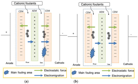
Figure 6.
Illustration of showing (a) the hypothesis and (b) the experimental result of the RED system with only one cell pair (the part within the dashed square) supplying seawater and river containing cationic foulants.
Figure 7 represents that the non-charged foulant, PEG 400, in the seawater stream strongly fouled IEMs due to strong adsorption to both CEM and AEM by macromolecule interaction. It could be the effect of the longest carbon chain in PEG 400 among the foulants used in this study on the electrical resistance of the stack. The non-charged foulant in a river stream also fouled IEMs significantly. The non-charged foulant in both streams shows a similar variation with the non-charged foulant in the seawater or river streams. The result is well matched with the expected result in Table 3. As illustrated in Figure 8a,b, the hypothesis and the real result should obtain the worst fouling in the RED system supplying either seawater or river containing non-charged foulants due to strong adsorption toward the surface of IEMs in either a seawater or a river stream.
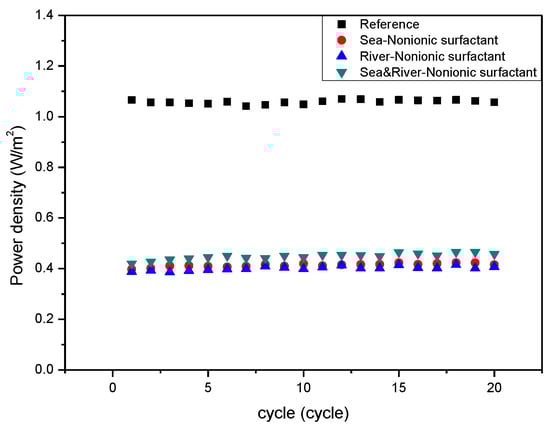
Figure 7.
Variation of power density of the RED systems with the number of operation cycles with respect to the presence of the non-charged foulant (PEG 400) included in seawater, river, or both.
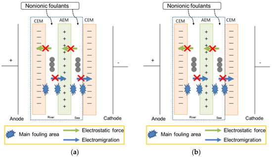
Figure 8.
Illustration of showing (a) the hypothesis and (b) the experimental result of the RED system with only one cell pair (the part within the dashed square) supplying seawater and river containing non-charged foulants.
In the case of the non-charged foulant, the proposed fouling mechanism well predicts the real result of fouling in the RED system. For the charged foulants, it was found that the opposite behavior occurs in the RED system. It was predicted that the fouling would be the worst when the foulants exist in seawater streams. However, it was observed that the worst fouling was shown when the foulants were present in river freshwater streams. To find the reason of the unexpected fouling behavior, the zeta potential of the seawater and the river freshwater in the presence of the charged foulants was measured to investigate the effect of the concentration of the NaCl supporting electrolyte. Foulant solutions with higher positive or negative zeta potential have higher potential to foul CEMs or AEMs, respectively [20]. As shown in Figure 9, the zeta potential of four different solutions was measured with the foulant concentration. Two different supporting electrolytes with higher concentration than those used in this study as seawater and river freshwater, i.e., 0.513 and 2.565 M NaCl, were used since the supporting electrolyte below 0.5 M did not provide the reliable measurement of the zeta potential of the solutions. This would result in magnifying the effect of supporting electrolyte concentration on the fouling to IEMs. In 0.513 M NaCl, the anionic and cationic foulant solutions represent strong negative and positive zeta potential, but, in 2.565 M NaCl, the zeta potential of both solutions becomes zero. It is believed that a similar result could be expected for the foulant solutions in 0.017 and 0.513 M NaCl supporting electrolytes. It means that the zeta potential of the foulants in higher concentration of supporting electrolyte is significantly mitigated since the Debye length of the charged foulants decreases due to the higher ionic strength of seawater streams and causes to lower net electrostatic effect.
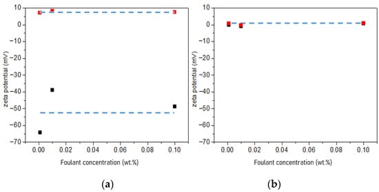
Figure 9.
Zeta potential of (a) the 0.001, 0.01, and 0.10 wt.% cationic foulant (CPC) (red square) and the 0.001, 0.01, and 0.10 wt.% anionic foulant (SDS) (black square) in 0.513 M NaCl and (b) the cationic foulant (CPC) (red square) and the anionic foulant (SDS) (black square) in 2.565 M NaCl.
4. Conclusions
Three different types of foulants, i.e., positively charged, negatively charged, and non-charged surfactants, have been investigated to figure out the fouling behavior of each foulant in a RED system in terms of the adsorption by electromigration, electrostatic attraction, and macromolecule interaction. The foulants were present in seawater, river freshwater, or both streams. In the case of the positively and negatively charged foulants, it could be expected that the worst fouling behavior is obtained in the RED system supplying the seawater in the presence of the charged foulants. However, the worst fouling tendency has been observed for the river freshwater in the presence of the charged foulants. The non-charged foulant was matched well with the proposed fouling behavior. The measurement of the zeta potential of the charged foulant solutions in a lower and a higher NaCl concentrations as supporting electrolyte resulted in the possible mechanism that a decrease in Debye length weakens the net electrostatic interaction between the charged foulants and the oppositely charged functional groups of AEM or CEM to make the fouling tendency less. It could foul IEMs less and result in maintaining RED performance longer. It reveals that, in RED systems, non-charged foulants or charged foulants present in river freshwater streams should be taken into account very cautiously by means of thorough anti-fouling control.
Author Contributions
Conceptualization: J.-S.P.; methodology: S.-J.H. and J.-S.P.; experimentation: S.-J.H. and J.-S.P.; validation: J.-S.P.; investigation: S.-J.H. and J.-S.P.; resources: J.-S.P.; writing—original draft preparation: S.-J.H. and J.-S.P.; writing—review and editing: J.-S.P.; supervision: J.-S.P.; project administration: J.-S.P.; funding acquisition: J.-S.P. All authors have read and agreed to the published version of the manuscript.
Funding
This research was funded by a 2018 Research Grant from Sangmyung University.
Institutional Review Board Statement
Not applicable.
Informed Consent Statement
Not applicable.
Data Availability Statement
Data sharing not applicable.
Acknowledgments
This research was funded by a 2018 Research Grant from Sangmyung University.
Conflicts of Interest
The authors declare no conflict of interest.
References
- Krakhella, K.W.; Morales, M.; Bock, R.; Seland, F.; Burheim, O.S.; Einarsrud, K.E. Electrodialytic Energy Storage System: Permselectivity, Stack Measurements and Life-Cycle Analysis. Energies 2020, 13, 1247. [Google Scholar] [CrossRef]
- Lee, S.; Shin, M.-S.; Park, J.-S. Anion-conducting Pore-filling Membranes with Optimization of Transport Number and Resistance for Reverse Electrodialysis. Chem. Lett. 2014, 43, 621–623. [Google Scholar] [CrossRef]
- Veerman, J. The Effect of the NaCl Bulk Concentration on the Resistance of Ion Exchange Membranes—Measuring and Modeling. Energies 2020, 13, 1946. [Google Scholar] [CrossRef]
- Clemente, A.; Castelló, R.C. Redox Flow Batteries: A Literature Review Oriented to Automatic Control. Energies 2020, 13, 4514. [Google Scholar] [CrossRef]
- Park, J.-S.; Shin, M.-S.; Kim, C.-S. Proton exchange membranes for fuel cell operation at low relative humidity and intermediate temperature: An updated review. Curr. Opin. Electrochem. 2017, 5, 43–55. [Google Scholar] [CrossRef]
- Lee, Y.; Kim, H.; Kim, D.-K. Power Generation from Concentration Gradient by Reverse Electrodialysis in Anisotropic Nanoporous Anodic Aluminum Oxide Membranes. Energies 2020, 13, 904. [Google Scholar] [CrossRef]
- Oh, Y.; Jeong, Y.; Han, S.-J.; Kim, C.S.; Kim, H.; Han, J.-H.; Hwang, K.-S.; Jeong, N.-J.; Park, J.-S.; Chae, S. Effects of Divalent Cations on Electrical Membrane Resistance in Reverse Electrodialysis for Salinity Power Generation. Ind. Eng. Chem. Res. 2018, 57, 15803–15810. [Google Scholar] [CrossRef]
- Gregory, K.B.; Vidic, R.D.; Dzombak, D.A. Water Management Challenges Associated with the Production of Shale Gas by Hydraulic Fracturing. Elements 2011, 7, 181–186. [Google Scholar] [CrossRef]
- Li, W.; Krantz, W.B.; Cornelissen, E.R.; Post, J.W.; Verliefde, A.R.; Tang, C.Y. A novel hybrid process of reverse electrodialysis and reverse osmosis for low energy seawater desalination and brine management. Appl. Energy 2013, 104, 592–602. [Google Scholar] [CrossRef]
- Straub, A.P.; Deshmukh, A.; Elimelech, M. Pressure-retarded osmosis for power generation from salinity gradients: Is it viable? Energy Environ. Sci. 2016, 9, 31–48. [Google Scholar] [CrossRef]
- Krakhella, K.W.; Bock, R.; Burheim, O.S.; Seland, F.; Einarsrud, K.E. Heat to H2: Using Waste Heat for Hydrogen Production through Reverse Electrodialysis. Energies 2019, 12, 3428. [Google Scholar] [CrossRef]
- Nazemi, M.; Zhang, J.; Hatzell, M.C. Harvesting Natural Salinity Gradient Energy for Hydrogen Production Through Reverse Electrodialysis Power Generation. J. Electrochem. Energy Convers. Storage 2017, 14, 020702. [Google Scholar] [CrossRef]
- Hatzell, M.C.; Ivanov, I.; Cusick, R.D.; Zhu, X.; Logan, B.E. Comparison of hydrogen production and electrical power generation for energy capture in closed-loop ammonium bicarbonate reverse electrodialysis systems. Phys. Chem. Chem. Phys. 2014, 16, 1632–1638. [Google Scholar] [CrossRef] [PubMed]
- Hatzell, M.C.; Zhu, X.; Logan, B.E. Simultaneous Hydrogen Generation and Waste Acid Neutralization in a Reverse Electrodialysis System. ACS Sustain. Chem. Eng. 2014, 2, 2211–2216. [Google Scholar] [CrossRef]
- Higa, M.; Watanabe, T.; Yasukawa, M.; Endo, N.; Kakihana, Y.; Futamura, H.; Inoue, K.; Miyake, H.; Usui, J.; Hayashi, A.; et al. Sustainable hydrogen production from seawater and sewage treated water using reverse electrodialysis technology. Water Pr. Technol. 2019, 14, 645–651. [Google Scholar] [CrossRef]
- Chen, X.; Jiang, C.; Zhang, Y.; Wang, Y.; Xu, T. Storable hydrogen production by Reverse Electro-Electrodialysis (REED). J. Membr. Sci. 2017, 544, 397–405. [Google Scholar] [CrossRef]
- Lee, S.-Y.; Jeong, Y.-J.; Chae, S.; Yeon, K.-H.; Lee, Y.; Kim, C.-S.; Jeong, N.-J.; Park, J.-S. Porous carbon-coated graphite electrodes for energy production from salinity gradient using reverse electrodialysis. J. Phys. Chem. Solids 2016, 91, 34–40. [Google Scholar] [CrossRef]
- Lee, H.-J.; Park, J.-S.; Moon, S.-H. A study on fouling mitigation using pulsing electric fields in electrodialysis of lactate containing BSA. Korean J. Chem. Eng. 2002, 19, 880–887. [Google Scholar] [CrossRef]
- Lee, H.-J.; Park, J.-S.; Kang, M.-S.; Moon, S.-H. Effects of silica sol on ion exchange membranes: Electrochemical characterization of anion exchange membranes in electrodialysis of silica sol containing-solutions. Korean J. Chem. Eng. 2003, 20, 889–895. [Google Scholar] [CrossRef]
- Park, J.-S.; Lee, H.-J.; Choi, S.-J.; Geckeler, K.E.; Cho, J.; Moon, S.-H. Fouling mitigation of anion exchange membrane by zeta potential control. J. Colloid Interface Sci. 2003, 259, 293–300. [Google Scholar] [CrossRef]
- Park, J.-S.; Lee, H.-J.; Moon, S.-H. Determination of an optimum frequency of square wave power for fouling mitigation in desalting electrodialysis in the presence of humate. Sep. Purif. Technol. 2003, 30, 101–112. [Google Scholar] [CrossRef]
- Park, J.-S.; Chilcott, T.; Coster, H.; Moon, S.-H. Characterization of BSA-fouling of ion-exchange membrane systems using a subtraction technique for lumped data. J. Membr. Sci. 2005, 246, 137–144. [Google Scholar] [CrossRef]
- Park, J.-S.; Choi, J.-H.; Yeon, K.-H.; Moon, S.-H. An approach to fouling characterization of an ion-exchange membrane using current–voltage relation and electrical impedance spectroscopy. J. Colloid Interface Sci. 2006, 294, 129–138. [Google Scholar] [CrossRef] [PubMed]
- Hansima, M.; Makehelwala, M.; Jinadasa, K.; Wei, Y.; Nanayakkara, K.; Herath, A.C.; Weerasooriya, R. Fouling of ion exchange membranes used in the electrodialysis reversal advanced water treatment: A review. Chemosphere 2021, 263, 127951. [Google Scholar] [CrossRef]
- Chon, K.; Jeong, N.; Rho, H.; Nam, J.-Y.; Jwa, E.; Cho, J. Fouling characteristics of dissolved organic matter in fresh water and seawater compartments of reverse electrodialysis under natural water condtions. Desalination 2020, 496, 114478. [Google Scholar] [CrossRef]
- Zhao, Z.; Shi, S.; Cao, H.; Li, Y.; Van Der Bruggen, B. Comparative studies on fouling of homogeneous anion exchange membranes by different structured organics in electrodialysis. J. Environ. Sci. 2019, 77, 218–228. [Google Scholar] [CrossRef]
- Rijnaarts, T.; Moreno, J.; Saakes, M.; De Vos, W.; Nijmeijer, K. Role of anion exchange membrane fouling in reverse electrodialysis using natural feed waters. Colloids Surf. A Physicochem. Eng. Asp. 2019, 560, 198–204. [Google Scholar] [CrossRef]
- Talebi, S.; Chen, G.Q.; Freeman, B.; Suarez, F.; Freckleton, A.; Bathurst, K.; Kentish, S.E. Fouling and in-situ cleaning of ion-exchange membranes during the electrodialysis of fresh acid and sweet whey. J. Food Eng. 2019, 246, 192–199. [Google Scholar] [CrossRef]
- Zhao, Z.; Shi, S.; Cao, H.; Shan, B.; Sheng, Y. Property characterization and mechanism analysis on organic fouling of structurally different anion exchange membranes in electrodialysis. Desalination 2018, 428, 199–206. [Google Scholar] [CrossRef]
- Mikhaylin, S.; Bazinet, L. Fouling on ion-exchange membranes: Classification, characterization and strategies of prevention and control. Adv. Colloid Interface Sci. 2016, 229, 34–56. [Google Scholar] [CrossRef]
- Riley, G.A. Particulate Organic Matter in Sea Water. Adv. Mar. Biol. 1971, 8, 1–118. [Google Scholar] [CrossRef]
- Curtis, P.J.; Adams, H.E. Dissolved organic matter quantity and quality from freshwater and saltwater lakes in east-central Alberta. Biogeochem. 1995, 30, 59–76. [Google Scholar] [CrossRef]
- Ion Exchange Membranes for Water Purification, Fujifilm Membrane Technology. Available online: https://www.fujifilmmembranes.com/images/IEM_brochure_1_1_-final_small_size.pdf (accessed on 2 December 2020).


Publisher’s Note: MDPI stays neutral with regard to jurisdictional claims in published maps and institutional affiliations. |
© 2021 by the authors. Licensee MDPI, Basel, Switzerland. This article is an open access article distributed under the terms and conditions of the Creative Commons Attribution (CC BY) license (http://creativecommons.org/licenses/by/4.0/).