Abstract
The current energy inefficiencies in relocatable temporary camps of the Armed Force troops create logistic challenges associated with fuel supply. The energy needs of these camps are primarily satisfied by diesel engine generators, which imply that a significant amount of fuel needs to be continuously provided to these camps, often built in remote areas. This paper presents an alternative solution, named Smart Hybrid Energy System (SHES), aiming towards significantly reducing the amount of fuel needed and minimizing transportation logistics while meeting camp energy demands. The SHES combines the existing diesel generators with solar power generation, energy storage, and waste heat recovery technologies, all connected to a microgrid, ensuring uninterrupted electricity and hot water supplies. All components are controlled by an energy management system that prioritizes output and switches between different power generators, ensuring operation at optimum efficiencies. The SHES components have been selected to be easily transportable in standard shipping 20 ft containers. The modularity of the solution, scalable from the base camp for 150 people, is designed according to available on-site renewable sources, allowing for energy optimization of different camp sizes in different climates.
1. Introduction
The Armed Forces operate in remote locations for training and military operations, even under natural disaster conditions or in foreign territories during conflicts, and must be ready to deploy on short notices, in any climate and for prolonged periods. As such, they currently rely on relocatable temporary camps (RTCs) for their deployments through extreme operational and environmental conditions. To sustain operations, as there is no utility grid, RTCs depend on logistics for the continuous supply of fossil fuel (primarily diesel) as the main source of energy. Inefficiencies in current practices lead to vulnerabilities in energy infrastructures, such as shortfalls in power generation and higher requirements for fuel resupply, with the knock-on effect of greatly increasing the transportation logistics during operations. Moreover, RTCs typically use spot generation by connecting loads to a common set of generators, where each generator is oversized to satisfy peak loads, even when these loads are infrequent. Consequently, generators typically are selected at a significantly higher capacity, resulting in an inefficient and costly source of power, increased maintenance, and wet sacking, a condition resulting from poor fuel combustion.
In recent years, military engineers have therefore encountered several operational challenges associated with energy logistic convoys and infrastructure, limited supplies, and climate change. Scientific literature identified a spectrum of approaches and technologies to address energy consumption under these conditions. Few combinations of components have been proposed according to the site-specific characteristics [1,2,3], however, the definition of further integrated configurations remains rarely investigated, although it is evident that the Armed Forces could benefit from holistically assessing these approaches as integrated systems.
Significant gains in the efficiencies of RTC utility systems (renewable energy systems; improved generators and energy storage or grid efficiency) and energy conservation measures (e.g., insulation of the camp tent fabric, building controls, etc.) would have an overall increasing benefit on the deployed operations. Meanwhile, stand-alone hybrid energy systems have been proposed as valuable means of supplying energy to remote areas, such as isolated rural villages [4,5,6,7], and for various other purposes, such as medical clinic practices [8] or military operations [9,10,11].
Some researchers investigated solutions aiming at reducing the dependency on fossil fuels during prolonged emergencies by proposing self-contained demonstration units that make use of hybrid generation from solar, wind, and biomass and, minimally, fossil sources [12]. Some of these systems have already been introduced to the market, as described below. Besides microgrids, clusters of electricity sources and load operating systems are being used to improve the reliability of electrical grids, manage the addition of distributed clean energy resources like wind and solar photovoltaic generation, reduce fossil fuel emissions, and provide electricity in areas not served by centralized electrical infrastructure [13].
Some models described the components of a microgrid [5,9,14,15], but not much is known about its behavior as a whole system. Some studies aimed to model microgrids at steady-state and study their transient responses to changing inputs [16]. However, researchers have built a full-scale microgrid model, including the power sources, power electronics, and load and mains models [5].
One of the main challenges towards the development of isolated microgrids is the management of various devices and energy flows to optimize their operations, particularly regarding the hourly loads and the availability of power produced by renewable energy systems. Energy management systems could be a solution to tackle these issues [16,17,18]. Regarding the provision of energy services with modular and transportable systems by making use of microgrid technology, some examples can be found in the market. For example, examples of possible technical solutions include the following:
- Power Box Containers by Out of the Box Energy Solutions (http://www.outofthebox.energy/power-box/powerbox-containers/)
- Energy Containers by Intech Clean Energy (https://www.intechcleanenergy.ca/energy-container/)
- Hybrid Smart Total by Golden Peniel Limited (http://gplnigeria.com/hybrid.html)
- Container Box Systems by Hakai Energy Solutions (https://www.hakaienergysolutions.com/services/container-box-systems/)
- Multi Box Microgrid by BoxPower (https://boxpower.io/products/multi-box-microgrid/)
- PowerPlus Hybrid Power Generator by Firefly (https://www.fireflyhybridpower.com/products/powerplus/)
- ES Box by Schneider Electric (https://solar.schneider-electric.com/product/es-box/)
The Cross-Power unit, e.g., uses modular hybrid wind and solar systems, integrated with battery storage, to produce electricity in remote locations. However, most of the existing solutions use black box intelligent energy management systems to ensure a continuous supply and avoid shortfalls in power generation.
This paper presents a scalable and transportable solution, named Smart Hybrid Energy System (SHES), for providing energy-efficient services to soldiers in protracted displacement situations. The SHES combines the existing diesel generators with solar power generation, energy storage, and waste heat recovery technologies, all connected to a microgrid, ensuring uninterrupted electricity and hot water supplies. The reliable and energy-efficient system helps to manage generator output. By transforming an independently operating system of generators into a demand-managed microgrid, SHES provides power only where and when it is needed, instead of completely relying on fuel-burning generators. The system also provides the Armed Forces with critically needed power surety by utilizing intelligent load management technologies to prevent grid collapse in the event of generator fault, as the SHES prevents a stoppage of energy flow by shifting demand onto supporting generators if one generator fails. The system is designed to manage the energy needs of a 150 to 1500-person RTC, operating in a temperate climate zone and allowing for the occasional deployment to extremely hot or cold climatic zones. Finally, this paper considers the energy savings achievable through technologies that improve the accommodation’s insulation, such as a thermoreflective multilayer system developed for emergency architecture, or that provide additional layers of solar protection, reducing the heat transfer through the shelter exterior thus reducing the daily air conditioning loads and reliance on diesel fuel [19,20].
2. Methodology
Regarding the design criteria of the RTCs solution, different technologies for energy production and storage concerning containerized solutions for emergencies were analyzed for the SHES. The equipment was selected from a range of commercial products based on sizing calculations and container space. The travel weight and volume, logistical support, required maintenance, and any hazards associated with the systems were also considered. Finally, for each of the selected technologies, detailed design work was conducted.
The system was proposed to the Canadian Armed Forces, and as such, the annual energy performance reported in this study was analyzed for the temperate climate zone of Brandon (Manitoba, Canada) at 49.85° N. Through dynamic energy and energy management simulations with a combination of software including the DoE Energy Plus and HOMER Pro software, the performance of the SHES system was analyzed.
First, an energy model reproducing the existing baseline 150-person military camp was created using Energy Plus, and data related to geometry, constructions, occupancy, HVAC, lighting, equipment, operation, climate, and energy management system (EMS) was assigned. Furthermore, the energy model was calibrated to match the actual net energy and heating energy consumptions of the RTCs and deriving and collating data from past RTC deployments as a reference for the design process. For this purpose, the net energy consumption was described as the combined energy consumptions of electricity generation and diesel-heating equipment. Second, the Energy Plus-generated electric and thermal hourly load profiles were imported to HOMER Pro, a microgrid design, simulation, and optimization tool, used for the purposes as a design and investment decision support tool for selecting the optimal portfolio, sizing, placement, and dispatch of the multiple energy sources feeding the decentralized energy system and serving the camp loads. HOMER Pro was also used in performing sensitivity analyses to identify the most cost-effective system configuration at various fuel costs and nominal discount rates.
The dynamic studies made it possible to conduct comparisons between different utility systems scenarios, comprising multiple distributed energy resources and energy conservation measures (i.e., advanced insulation materials), over the current base camp practices. Further simulations were subsequently made on the most cost-effective proposed solution to estimate the annual fuel use and energy savings for different climate zones.
In order to evaluate the economic and technical feasibility of the many options and to account for variations in technology costs and energy resource availability, the operation of the different system configurations was simulated in HOMER Pro by performing dynamic energy balance. For each time step and for each system configuration considered, HOMER Pro compared the electric and thermal demand to the energy that the system can supply and calculated the flow of energy to and from each component of the system. In each time step, the analyses focused on how to operate the generators and whether to charge or discharge the batteries and determined whether a configuration is feasible. The study also looked at the system cost calculations in terms of capital, replacement, operation and maintenance, fuel, and interest rates. Furthermore, HOMER Pro used optimization algorithms to search for the most cost-effective system configuration in terms of net present cost (life cycle cost). Details about the calculations are available in the HOMER Pro user manual [21].
It is important to note that the lowest net present cost did not necessarily indicate the lowest energy consumption; however, incorporating the operational costs in the calculation, it was used to find the optimal system design rather than net energy consumptions.
2.1. Case Study
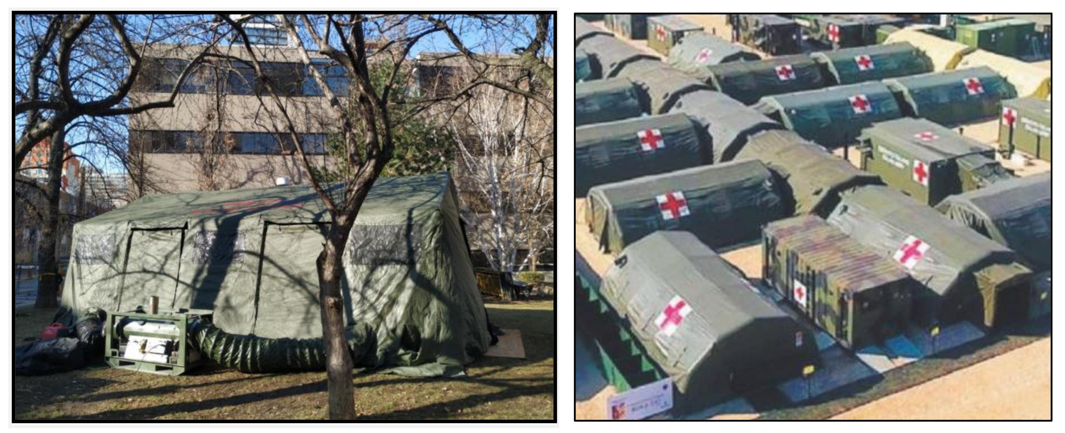
RTCs provide accommodations, administration shelters, ablutions, maintenance, storage, hangar, and kitchen facilities. RTCs generally include tents identical to those deployed by militaries throughout the world (Figure 1). The population supported by RTCs can vary considerably from day to day, depending on operational activities as well as surges due to the rotation of personnel. Deployed personnel are provided a bed space in a tent that holds 4–10 people. The accommodations are located in a condensed area adjacent to the ablutions. Ablutions units are composed of a shower, a toilet, and a sink, each unit serving 10 members of the camp population.
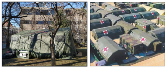
Figure 1.
Tent demonstration unit in Toronto, ON, built within Ryerson University (left) and full assembly of relocatable temporary camp (RTC) (right).
Multiple, independent systems are in place for electrical power generation and distribution, heating and cooling, storage and distribution of fuel and water, and waste disposal. These systems are not designed to promote energy efficiency. The current energy management approach in RTCs relies on diesel-powered generators for electricity production. Electrical energy is provided to the camp via multiple single-speed generator farms that incorporate variants of 300, 350, and 500 kW generators.
To avoid low load operation, load banks are employed to keep the generators running at optimal conditions and efficiency points. Excess electricity not required in the camp is ultimately diverted to a load bank where it is converted to waste heat. In the current “baseline” scenario, diesel-fired space heaters are used for heating. Cooling is provided by electric environmental conditioning units. Heating and cooling units are attached to each tent and are controlled by individual users.
2.2. Energy Modeling
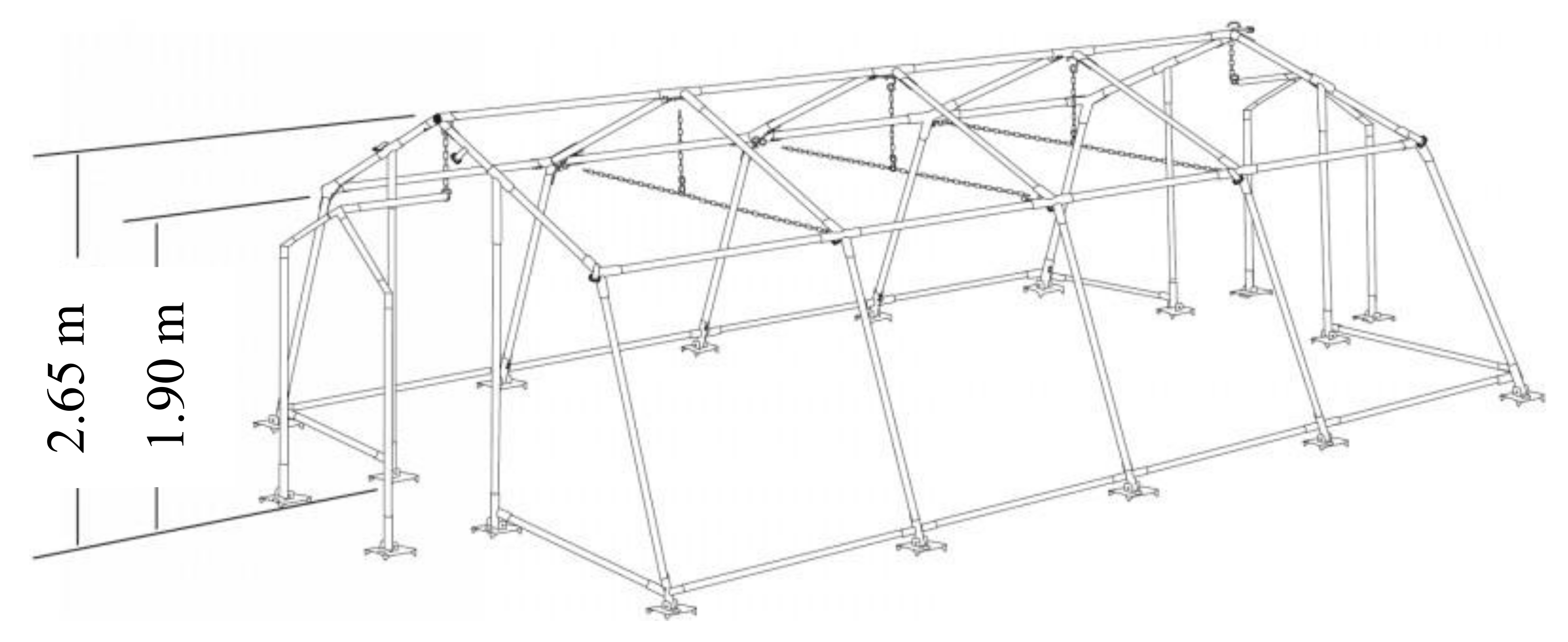
The virtual model reproducing the existing base camp (baseline) was sized for accommodating 150-persons and included 15 accommodations, each hosting 10 persons, 15 ablutions, administration, maintenance, laundry and storage hangar, kitchen, and dining facilities (Table 1). Each accommodation tent was 5.80 m length and 5.10 m width, with a medium internal height of 2.30 m. Data have been obtained in line with the technical sheet of the model by Montana 29 tent, Ferrino (Figure 2). The relative U-values of the envelope reported in Table 2 were estimated assuming that the standard shelter system was a canvas tent with low thermal resistance, in agreement with the literature [19].

Table 1.
Modeled zone properties of the military base camp.

Figure 2.
Geometric characteristic of the modeled tent.
Table 2.
Modeled envelope construction: thermal properties of the fabric tent of the military shelters.
Camp electric power capacity was sized for 1.5 kW/person, considering data related to past RTC deployments. Specific electrical load profiles were also taken into consideration. Generators were sized with a 10% overload and a further 10% expansion capability factor.
Typical fuel consumption for a 1.5 kW/person load provision was approximately 2000 L of diesel per person per year. Besides, it was assumed that 500 L of diesel fuel per person per year was used for direct combustion, which after accounting for an 80% efficiency, provided 15 GJ of energy for space heating.
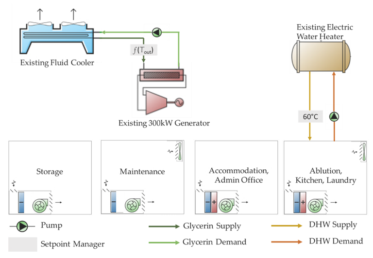
Figure 3 shows the detailed HVAC system and power generation scheme of the base camp, which, for a 150-person camp size, has a total diesel consumption including heating of 2500 L/person*year, has a heating diesel consumption of 500 L/person*year, and allows a hot water consumption of 30 L/person*day.
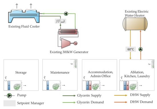
Figure 3.
Baseline camp: HVAC system and power generation scheme for a base camp.
Solution designs were also conceived to operate for prolonged periods in extremely hot (up to 50 °C) or cold (down to −40 °C) climates, as well as in all the temperate climatic conditions. Temperature, precipitation, daylight, and wind data of a temperate climate zone, Brandon, Manitoba, Canada, was used for all design calculations as required by the Canadian Defense Department. Further simulations were made to analyze the proposed system performance in different climate zones with severe conditions, including: Vancouver (British Columbia, Canada), Kanoya (Japan), Churchill (Manitoba, Canada), and Changi (Singapore).
3. Results
3.1. Smart Hybrid Energy System (SHES) Design
The SHES is designed to work in stand-alone mode or connected to the local grid. The SHES combines into a single, integrated system of the following technologies: (a) photovoltaic (PV) array, (b) an energy storage system, (c) existing diesel generators, (d) waste-to-heat energy recovery system (WHRU) for space heating, (e) solar hot water (SHW) system for domestic hot water, and (f) energy management system (EMS) that actively monitors and manages base camp equipment and zones.
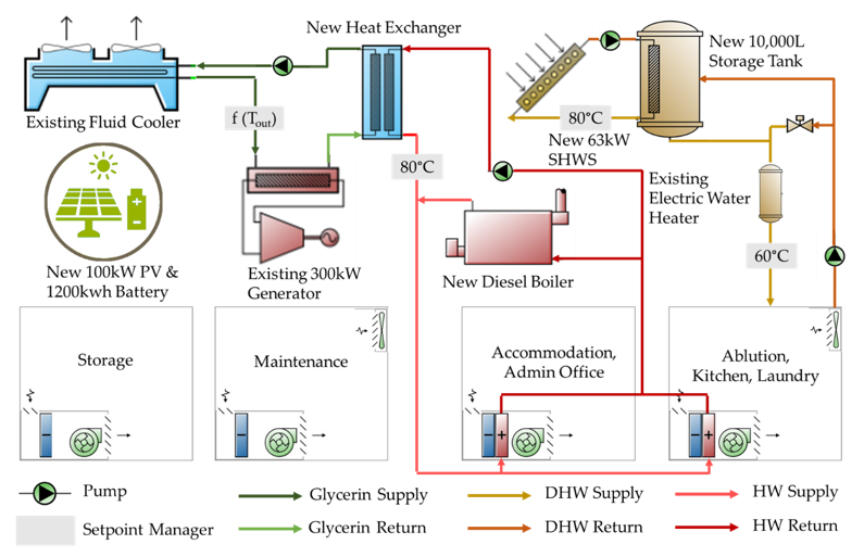
Figure 4 shows the SHES schematic configuration of the energy vectors, while Figure 5 shows the detailed HVAC system and power generation scheme of the SHES.
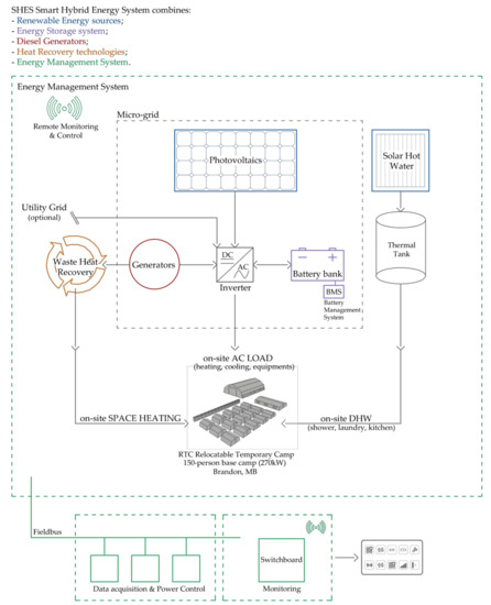
Figure 4.
Smart Hybrid Energy System (SHES) schematic configuration of the energy vectors.
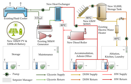
Figure 5.
Smart Hybrid Energy System (SHES): detailed HVAC system and power generation scheme.
In particular, the SHES system was composed of the following components:
- PV modules, with a 21% efficiency (SPR-X21-345) and a combined power output of 100 kW with a surface of 446 m2, are strung together. Each array is south-oriented with an optimized tilt angle, which varies by location, anchored to the ground with a mounting aluminum system. As the base camp loads use alternating current (AC), inverters are used to transform the direct current (DC) produced from PV. It is important to note that to satisfy the entire energy demand of the camp, the PV configuration would have employed a larger system (about four times larger); however, considering the army requirements for continuous transportation and reinstallation in addition to the high initial costs of the system and the spatial limitations, the PV system was sized to sufficiently cover the peak electric loads except for cooling; thus, only systems up to 100 kW were considered.
- Energy storage allows overcoming the intermittent nature of renewable energy sources. When PV systems have a peak above the load, the surplus energy is stored in sodium–sulfur batteries. On the other hand, when there is a high energy demand and the electricity generated by the PVs is insufficient, the batteries are discharged. The cells are monitored and protected by a battery management system (BMS). Various battery models were considered, and the most cost-effective model was selected. In particular, containerized NAS lithium-ion energy storage system by BASF was found to be a cost-effective solution for this project purposes due to its relatively large capacity (1250 kWh), discharge output (286.1 kW max), long duration (4.4 h), long lifespan (20 years or 6,250,000 kWh), reasonable warranty periods (10 years), and physical sizing considerations. A 40% minimum state of charge was assumed, while an 80% state of charge setpoint was found to be the most cost-effective strategy, as discussed later.
- Existing internal combustion diesel generator was integrated into the microgrid to ensure continuous power supply. A 15% minimum part-load ratio was assumed.
- WHRU allows recovering the waste heat from generators to use it for space heating (combined heat and power), which is supplemented by an efficient (89%) diesel boiler. The WHRU consisted of counter-flow heat exchangers and water-distribution systems, delivering hot water to terminal heating equipment. The terminal heating equipment was modeled as fan–coil units.
- SHW system used has a surface of 90 m2 and a power of 63 kW that supplies a significant fraction of the base camp domestic hot water (DHW) requirements, while the remaining portion is satisfied by the existing electric water heater. The strategy undertaken allows a 10,000 L storage tank to reach a higher temperature (80 °C) to increase the efficiency of the SHW system.
- EMS controls all components and ensures grid stability, continuously balancing energy generation, and consumption. It maximizes the power output by establishing a hierarchy of sources and prioritizing the use of renewable energy while optimizing the interactions between different components. The EMS is equipped with real-time remote monitoring and controls the base camp parameters, enabling central and informed decisions.
The selection of equipment from a range of commercial products was made based on 20 ft container space (Table 3) in addition to sizing calculations (Table 4) to optimize the annual energy production.
Table 3.
Key components dimensions of the Smart Hybrid Energy System (SHES).
Table 4.
Components of the Smart Hybrid Energy System (SHES) for a 150-person relocatable temporary camp (RTC) in Brandon, MB.
The system is adaptable to different installation and climates, and it was designed such that some existing equipment could be incorporated into the system, thus reducing investment costs for the Army. At the same time, individual components could be integrated without being tied to one manufacturer too. Consequently, the models of the components reported in Table 3 are only indications of possible solutions, as the system could integrate alternative components with comparable performances.
Other renewables can also be optionally integrated into the microgrid according to their on-site availability. The SHES is fully scalable for electric power outputs of 270 kW up to 2.7 MW to meet the varying energy needs from 150 to 1500-persons base camps. Several units of the system, eventually centralized at each tent, can be interconnected to complement the system provided for a 150-person base camp with a larger operational power range. The scaling options include the deployment of additional PV arrays, supplementary battery units, larger power generators, a large-scale WHRU, and a large-scale SHW system.
The SHES design architecture provides redundancy to ensure continuous operation through any subsystem failure, while the microgrid supply power guarantees the longer service and lifespans. The hybrid power generation design prioritizes renewable, followed by battery power, resulting in less generator runtime, thus requiring less maintenance. The EMS allows for identifying operations and maintenance issues before they become problematic, improving problem response time while contributing to the overall system reliability. Furthermore, the central and remote monitoring of the system parameters improves the maintenance supervision, scheduling, and management control. The proposed solution is provided with fire protection and security functions. The SHES incorporates existing technologies and state-of-the-art components; therefore, eventual replacements parts are widely available in the market. The system is prewired, preconfigured, and designed to be rapidly deployed as a plug and play system, following minor on-site assembly.
3.2. Energy Simulation Results
Energy simulations were conducted to quantify the reduced energy demand of the combination of microgrid, renewable resources, and energy recovery measures.
Figure 6 shows the results obtained using different software for the baseline scenario in different climate zones. Maximum differences of 6% and 8% were obtained for the heating and net energy consumptions in Vancouver (BC), respectively. This confirmed the validity of the approaches followed in modeling.
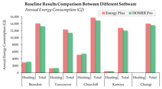
Figure 6.
Comparison between Energy Plus and HOMER Pro software for the current base camp practice (Baseline) for a 150-persons base camp in different climate zones.
Table 5 reports the simulation results for the annual energy consumption of a 150-persons RTC in Brandon (MB) according to different scenarios: Baseline, Solar Hot Water, Microgrid: generators + battery, Microgrid with a Waste Heat Recovery (a counter-flow fluid heat exchanger), Microgrid with a PV array (100 kW PV system to cover peak electric loads excluding cooling), and the scenario with all SHES technologies integrated.
Table 5.
Simulation results of the annual energy consumption for a 150-persons RTC in Brandon, MB, for the various scenarios with new technology solutions incrementally adopted.
The simulation results indicated that up to 37% fuel savings over current base camp configurations are achieved when all the SHES technologies are implemented for accommodating 150-person in a temperate climate (Brandon, MB) (Figure 7). Considered individually, the most impactful technology was found to be the Microgrid with a Waste Heat Recovery system (scenario 4), as evident in both Figure 7 and Table 5 and Table 6.
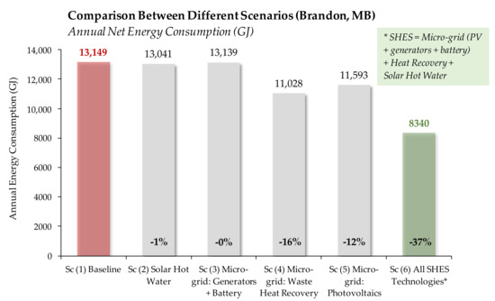
Figure 7.
Comparison between different utility systems scenarios: annual energy consumption savings over the current base camp practice (Baseline) for a 150-persons base camp in Brandon, MB.
Table 6.
Summary of simulation results for the various scenarios for a 150-person RTC in Brandon, MB.
The technoeconomic assessment indicated that the implementation of all SHES technologies significantly reduced the net-present cost (life cycle cost), defined as the present value of all installation and operation costs over the project lifetime, excluding the present value of all the revenues earned over the same interval.
Actual components’ costs were used in the analysis. The project lifetime was assumed to be 25 years, while an 8% nominal discount rate, defined as the simple interest rate on borrowed capital before factoring the inflation rates in, was assumed. The inflation rate was also assumed to be 2% over the project lifetime, and it was used in combination with the nominal discount rate to calculate the real discount rate, which is used to convert between one-time and annualized costs. Finally, the fuel (diesel) cost was assumed to be $1.00 for each liter.
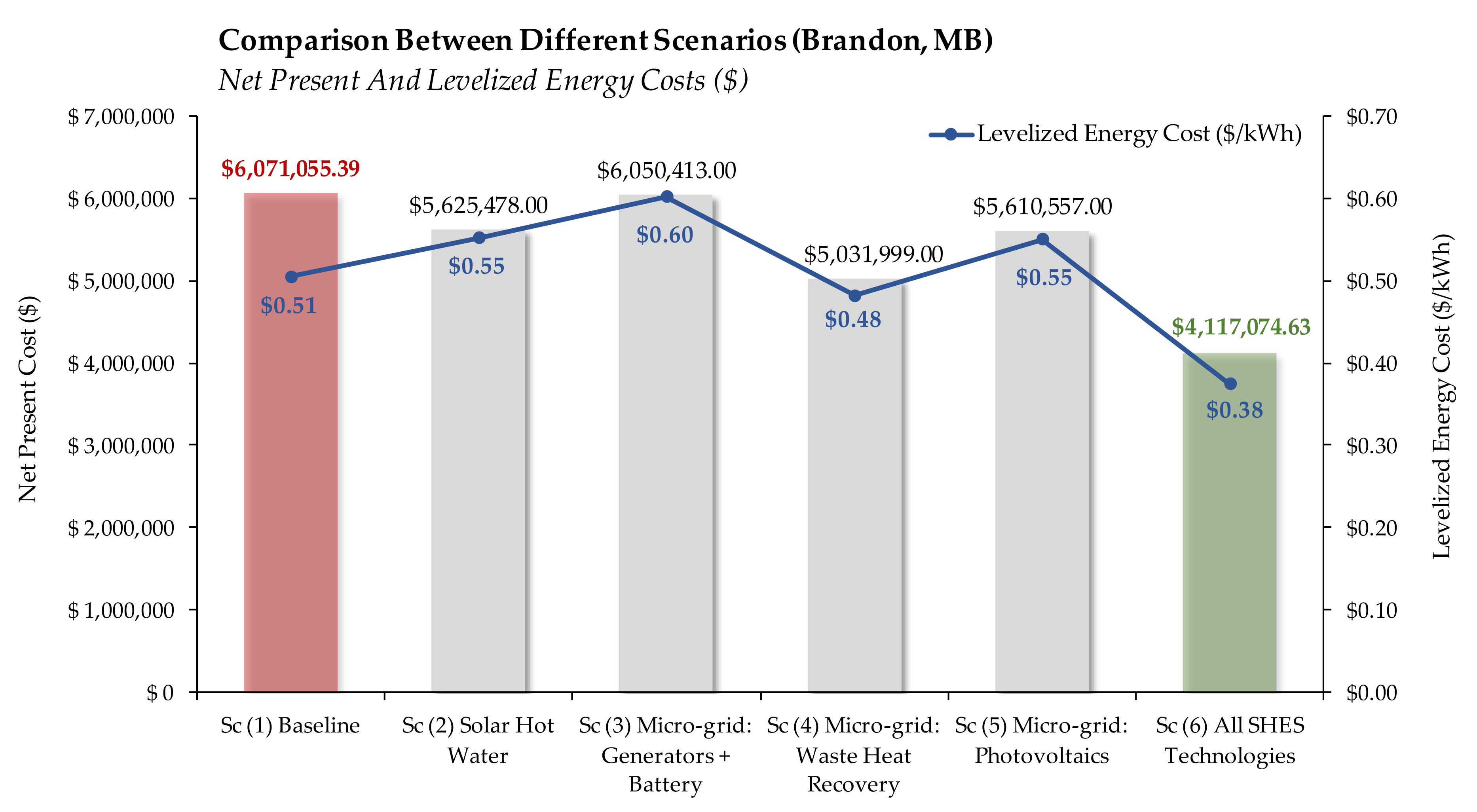
Results indicated that up to 32% reduction in net present value over current base camp configurations are achieved when all the SHES technologies are implemented for accommodating 150-person in a temperate climate (Brandon, MB) (Figure 8). The levelized cost of energy was also significantly reduced by 25%, as indicated. Figure 8 shows that the SHES acts as the most cost-effective solution; thus, it is the optimal solution that maximizes the use of renewable-generated energy while minimizing the project lifetime capital costs. More importantly, it is evident that the consideration of individual technologies eliminated the benefits gained from the integrated solution, and in fact, most technologies (except for WHRU), although reducing the net-present costs compared to the baseline, produced increased levelized energy costs due to their high initial costs and limited energy savings and utilization of all available energy resources when compared to SHES.

Figure 8.
Comparison between different utility systems scenarios: net present cost and levelized energy cost over the current base camp practice (Baseline) for a 150-persons base camp in Brandon, MB.
Diesel costs may vary overtime and by the region it is sold depending on the cost of crude oil. Similarly, interest rates fluctuate overtime, being influenced by the economic growth, fiscal and monetary policies, and inflation rates. Thus, it is critical to design an optimal system in terms of life cycle costs at the expected fuel and interest rates.
A sensitivity analysis was conducted to evaluate the proposed system due to variations in the nominal discount rates and diesel costs (Figure 9). As evident, SHES acts as the optimal system design for the widest range of fuel and simple interest rates, assuming a constant inflation rate of 2%. In particular, the baseline configuration is only considered cost-effective at combined low fuel rates and high simple interest rates. It is also evident that the SHES’s selected photovoltaics, energy storage, and converter capacities are optimal at the specified fuel cost and interest rates of $1/L and 8%, respectively. On the other hand, reducing these capacities would act as a more cost-effective solution at combinations of low and high fuel and simple interest rates, respectively.
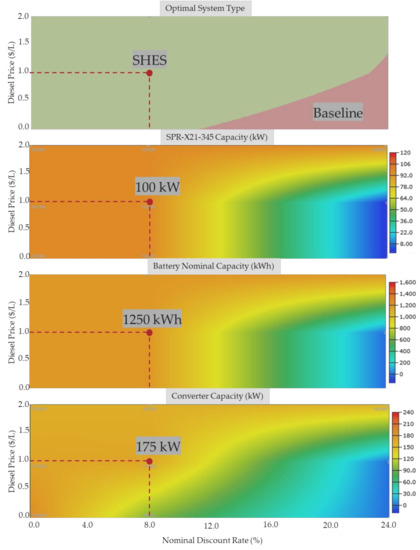
Figure 9.
Optimal system design for variations in diesel price and nominal discount rate.
As discussed earlier, only PV capacities up to 100 kW, which sufficiently covers the camp peak electric loads excluding the cooling loads, were considered to reduce initial costs and due to spatial and logistics purposes. Also, various battery and converter models and capacities were considered, and the most cost-effective configurations were selected considering the preselected PV size. Figure 9 shows that the optimal battery capacity is strictly influenced by the selected PV capacity, thus, using a lower PV capacity would imply using a smaller battery capacity except in cases where the interest rates are incredibly high, for which investing in energy storage would not be cost-effective at all. Similarly, the converter capacity is dependent on the selected PV capacity. However, the rate of capacity reduction is higher than that of the battery, particularly at moderate interest rates (8%–12%), driven by high converter capital costs when compared to energy storage and PVs.
One of the main challenges towards the development of isolated microgrids is the management of the various devices and energy flows to optimize their operations, particularly regarding the hourly loads that must be served, and the availability of power produced by renewable energy systems depending on daily and seasonal variations. The SHES combines the existing diesel generators with solar power generation, energy storage, and waste heat recovery technologies, all connected to a microgrid, ensuring uninterrupted electricity and hot water supplies. The reliable, energy-efficient system helps to manage generator output. By transforming an independently operating system of generators into a demand managed microgrid, SHES provides power only where and when it is needed, instead of completely relying on fuel-burning generators. A critical part of designing SHES was understanding the electric and thermal load and generation profiles to identify the most cost-effective energy management strategy while maximizing the renewable generation, without significantly increasing the initial costs of system while considering army spatial and logistic requirements. It is crucial to identify the parts of the system that carry these loads at different times of the day and different seasons, particularly at peak loads. The peak electric load typically occurs during the warmest period of the year due to increased cooling loads, while thermal loads during the same period would be low due to the absence of heating requirements. For these purposes, various dispatching strategies were considered for energy management purposes of controlling generator and battery operation in periods of insufficient renewable energy to supply the load, including “cycle charging” and “load following” strategies. A cycle charging dispatching strategy was found to be the most cost-effective. The cycle charging strategy implies that the generator runs at its maximum power output when it is needed to serve the electrical loads, while any surplus electrical production is diverted towards charging the battery until the battery setpoint state of charge of 80% is reached. This is accomplished by selecting the optimal combination of power sources, based on fixed and marginal costs, to serve the electric and thermal loads at the minimum cost and excess electricity production, while still satisfying the operating reserve requirements. On the other hand, a load following strategy, which implies that the generator produces enough power only to serve the load while the battery is charged by the renewable sources, would be more cost-effective in situations where the renewable generation is comparable to the magnitude of the served load.
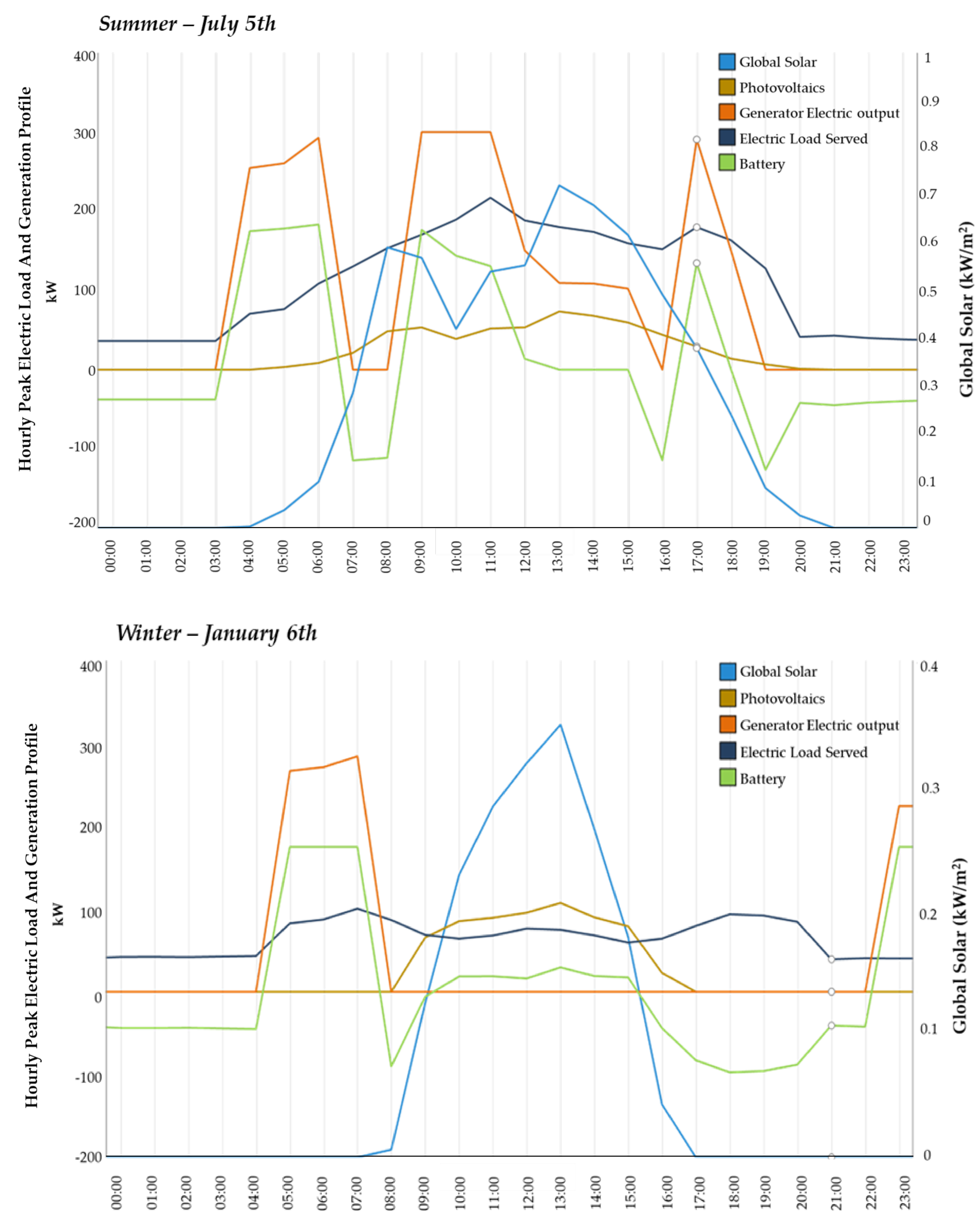
The results of the control strategy can be observed in Figure 10 and Figure 11, which show the electric and thermal and the generation profiles for the summer and winter peak demand days, respectively. The electric load served is initially constant and relatively low during early and late hours of the summer days and in the absence of solar radiation (Figure 10). Thus, this low electric load is satisfied solely by the energy stored in the battery while the generators are off. As the electric load starts to increase, the generators are turned on to satisfy parts of these loads, while the remaining parts are satisfied using the PV-generated power. To reduce the generator runtimes, at several intervals of the day, the reliance of the generator is reduced and eventually eliminated. At the same time, the loads are still being served by the energy stored in the battery during the previous hours. For the winter day, similar trends can be seen. However, due to lower electrical loads and increased PV generation as a result of a lower sun altitude, after the generators are turned on to serve partial loads and charge the battery, they are turned off for extended periods of the day, thus significantly reducing fuel consumption by relying on renewable resources. The generator’s runtime was reduced considerably to 4600 h (48% reduction) compared to 8760 h for the baseline configuration. It is also evident that the system could benefit from a greater PV size due to the high availability of solar radiation that is not being taken advantage of in both summer and winter months.
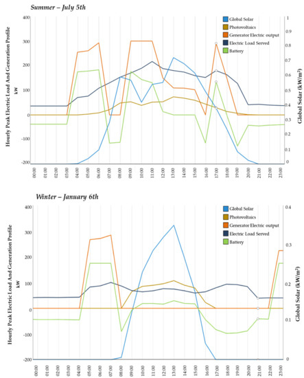
Figure 10.
SHES dynamic electric load management for a 150-persons base camp in Brandon, MB, in summer and winter peak days.
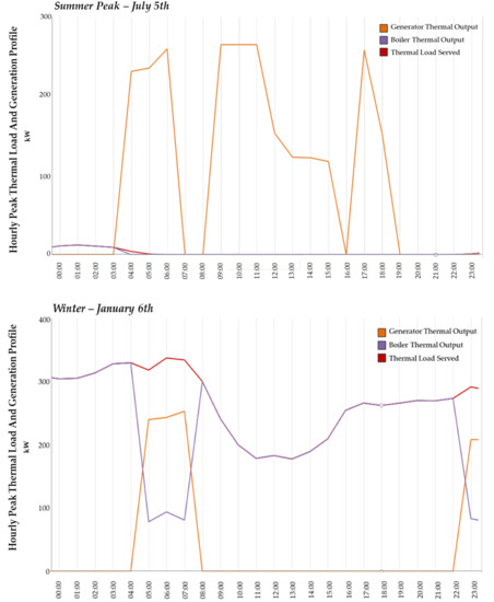
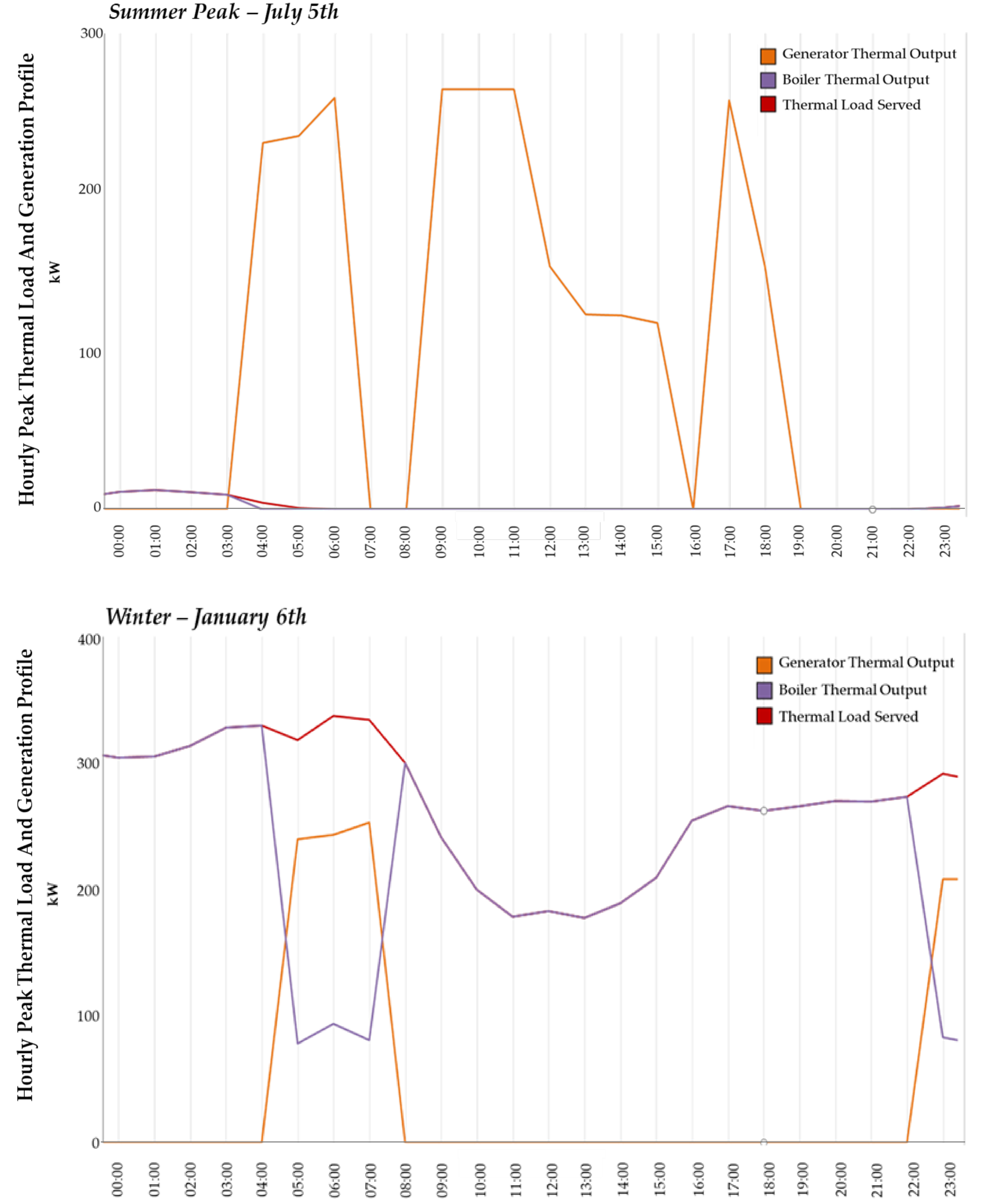
Figure 11.
SHES dynamic thermal load management for a 150-persons base camp in Brandon, MB, in summer and winter peak days.
In Figure 11, the thermal loads are very low in summer due to the absence of heating requirements while some heating is only required during night times, which suggested increasing the insulating properties of the tent fabrics. In the winter, the peak thermal heating load is served mainly using the diesel boiler, which is supplemented by the waste-to-heat recovery system that uses the generator’s heat to warm up the water delivered to the terminal fan–coil units. This heat is drawn from the generator only when it is running to serve the electrical loads during the winter; therefore, the WHRU system can only serve a part of the daily thermal load, which highlights the importance of considering synergies and differences between the different seasonal loads and designing a cost-optimal system in regards to full-year expected loads and availability of resources. It is also evident that a significant amount of excess heat is wasted in the summer months due to the absence of a simultaneous end use, thus, a heat storage system might be beneficial to store the heat and allowing for its use when needed in the colder months or in cold summer nights.
The SHES solution for the camp was also simulated in different geographic locations, to evaluate its performance, feasibility, and expected energy savings outcomes in different climate zones. In particular, the analysis involved the city of Vancouver (British Columbia, Canada), Kanoya (Japan), Churchill (Manitoba, Canada), and Changi (Singapore). Results indicated that fuel reductions from 21% up to 39% are also achievable for extremely hot and frigid climates when the solar collectors’ tilt and orientation are optimized for the specific location (Table 7). It is important to note that the solution was not reoptimized for different locations except for the PV and SHW tilt angles, and component and system sizes were kept constant to satisfy the army requirements of standard sizing.
Table 7.
Simulation results for extreme climatic zones when all SHES technologies are implemented.
3.3. Environmental Considerations
The SHES reduces the dependency on fossil fuel lowering the environmental footprint of RTCs since the transportation logistics are minimized and the consumption of vehicle-fuel transporting fuel to the base campsite is also reduced. The generators, rather than being fueled by diesel (as currently done in Canadian Armed Forces), could be powered by LPG (Liquefied Petroleum Gas) to produce lower amounts of harmful greenhouse gases. However, the risks due to the transportation of more hazardous materials must be considered.
Table 8 reports significant annual CO2 emissions savings compared to the baseline when all the SHES technologies are implemented for accommodating 150-person in a temperate climate (Brandon, MB). CO2 reductions up to 39% are also achievable with the deployment of the system in extreme hot and cold climates (Table 8). The CO2 emissions were calculated based on the annual diesel consumption to produce power by the generator and thermal energy by the boiler, assuming an emissions factor of 2.4 kg-CO2e produced as a result of burning each liter of consumed diesel. It was also assumed that diesel has a carbon content of 88%.
Table 8.
CO2 annual emissions for different scenarios of a 150-person RTC operating in different climates.
The SHES is designed to be easily integrated with other water and waste infrastructure systems, e.g., it could be combined with deployable water purification systems (e.g., Aspen Water) powering them as AC loads or using directly the solar energy of the photovoltaic panels or with deployable waste-to-energy systems (e.g., Energos Technology and Eco Waste Solution), which convert wastes into thermal energy (e.g., DWECX-TEEPS) that can be used locally. Moreover, the waste heat coming from the waste converter exhaust of the waste-to-energy system could be captured and used to produce space heating.
3.4. Enhanced RTC Construction
The existing standard RTCs are constructed with materials (canvas) that suffer from poor thermal performance leading to higher heating and cooling energy consumptions to maintain the thermal comfort of deployed soldiers. Consequently, the low thermal resistance of the existing shelter systems requires the design of bigger HVAC systems. Standard tents are constructed of such materials mainly due to their lightweight and waterproofing abilities, allowing for their easier transportation, installation, and long service life. However, recent developments in innovative materials made it possible to provide such properties combined with improved thermal performance to achieve higher energy savings [23,24]. Notably, 13 mm aerogel-enhanced blankets were proposed to be integrated into the existing construction to make significantly improved RSI-values of 0.625 m2K/W compared to 0.175 m2K/W as demonstrated in Table 2 earlier [23]. Such blankets have an extremely low thermal conductivity of 0.015 W/m. K, while having low toxicity, low density of 200 kg/m3, excellent fire rating, and high recyclability. Figure 12 shows a recently patented aerogel blanket obtained at Ryerson University using an ambient pressure drying (APD) process.
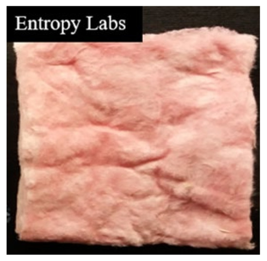
Figure 12.
New aerogel-enhanced blanket obtained by the authors and used to enhance the tent material fabric providing higher thermal resistance.
Energy simulations were conducted to assess the energy performance of the camp integrating SHES and high-performance tents incorporating the aerogel blanket produced into the interior of the existing canvas. Table 9 reports the results for different climate zones. The results show that enhancing the thermal resistance of the RTCs has significant impacts on increasing the camp energy efficiency for all climate zones. When compared to Scenario 6 results (SHES), it becomes clear that aerogel-enhanced blankets have their highest energy reduction impacts in extreme climates as Churchill, while still offering significant reductions in the other climate zones.
Table 9.
Energy consumption and CO2 annual emissions results for different scenarios (SHES and aerogel blanket are used) of a 150-person RTC operating in different climates.
4. Conclusions
This paper has described a new solution for a military army camp. The new approach shows significant improvements over the existing solutions thanks to the combination of microgrid with energy storage systems, renewable resources, and waste heat recovery technologies to reduce the fuel supply to RTCs significantly. In particular:
- A properly sized SHW system can supply a significant fraction of a base camp water heating requirements using solar energy;
- Modeling indicates that a combination of smart microgrid and renewable energy sources can reduce base camp energy demand and fuel use significantly, in addition to a significant carbon emission reduction. Considered individually, the technology with the lowest energy consumptions (up to 16% reduction) is the microgrid connected waster heat recovery system (scenario 4);
- Smart microgrids with energy storage systems supply power with improved voltage and frequency stability increased grid reliability and longer life of end use equipment;
- The EMS, equipped with real-time monitoring and control of base parameters, enables central and informed decision making. Configurable automatic load distribution provides the potential for reducing camp energy consumption for normal operations and unplanned events;
- The simulation results indicated that up to 37% of fuel savings and up to 37% annual CO2 emissions savings over current base camp configurations are achieved when all the SHES technologies are implemented in a temperate climate;
- Fuel and CO2 reductions from 21% up to 39% are also achievable for extremely hot and frigid climates when the solar collectors’ tilts are optimized.
Author Contributions
Conceptualization, U.B. and E.T.; methodology U.B., E.T., and K.K.; software, K.K.; data curation, U.B. and E.T.; writing—review and editing, U.B.; and supervision, U.B. All authors have read and agreed to the published version of the manuscript.
Funding
The authors would like to thank the financial support provided by the Government of Canada through the Pop-up City project. They would like to gratefully thank ISSNAF (Italian Scientists and Scholars in North America Foundation) and Italian National Order of Engineers for funding a scholarship for allowing the second author to dedicate time to this project.
Conflicts of Interest
The authors declare no conflicts of interest.
References
- Cioccolanti, L.; Fonti, A.; Comodi, G. Dynamic Modeling of Thermal and Electrical Microgrid of Multi- Apartment in Different European Locations. In Proceedings of the 17th International Stirling Engine Conference and Exhibition, Northumbria University, Newcastle upon Tyne, UK, 24–26 August 2016. [Google Scholar]
- Razmjoo, A.; Shirmohammadi, R.; Davarpanah, A.; Pourfayaz, F.; Aslani, A. Stand-alone hybrid energy systems for remote area power generation. Energy Rep. 2019, 5, 231–241. [Google Scholar] [CrossRef]
- Ismail, M.; Moghavvemi, M.; Mahlia, T.M.I. Techno-economic analysis of an optimized photovoltaic and diesel generator hybrid power system for remote houses in a tropical climate. Energy Convers. Manag. 2013, 69, 163–173. [Google Scholar] [CrossRef]
- Ghasemi, A.; Asrari, A.; Zarif, M.; Abdelwahed, S. Techno-economic analysis of stand-alone hybrid photovoltaic–diesel–battery systems for rural electrification in eastern part of Iran—A step toward sustainable rural development. Renew. Sustain. Energy Rev. 2013, 28, 456–462. [Google Scholar] [CrossRef]
- Puglia, G.; Moroni, M.; Fagnani, R.; Comodi, G. A Design Approach of Off-grid Hybrid Electric Microgrids in Isolated Villages: A Case Study in Uganda. Energy Procedia 2017, 105, 3089–3094. [Google Scholar] [CrossRef]
- Daud, A.-K.; Ismail, M.S. Design of isolated hybrid systems minimizing costs and pollutant emissions. Renew. Energy 2012, 44, 215–224. [Google Scholar] [CrossRef]
- Zhai, H.; Dai, Y.; Wu, J.; Wang, R. Energy and exergy analyses on a novel hybrid solar heating, cooling and power generation system for remote areas. Appl. Energy 2009, 86, 1395–1404. [Google Scholar] [CrossRef]
- Higier, A.; Arbide, A.; Awaad, A.; Eiroa, J.; Miller, J.; Munroe, N.; Ravinet, A.; Redding, B. Design, development and deployment of a hybrid renewable energy powered mobile medical clinic with automated modular control system. Renew. Energy 2013, 50, 847–857. [Google Scholar] [CrossRef]
- Kashem, S.B.A.; De Souza, S.; Iqbal, A.; Ahmed, J. Microgrid in military applications. In Proceedings of the 2018 IEEE 12th International Conference on Compatibility, Power Electronics and Power Engineering (CPE-POWERENG 2018), Doha, Qatar, 10–12 April 2018; Institute of Electrical and Electronics Engineers (IEEE): New York, NY, USA, 2018; pp. 1–5. [Google Scholar] [CrossRef]
- Van Broekhoven, S.B.; Judson, N.; Nguyen, S.V.; Ross, W.D. Microgrid Study: Energy Security for DoD Installations. Lincoln Lab. 2012. [Google Scholar]
- Skowronska-Kurec, A.G.; Eick, S.T.; Kallio, E.T. Demonstration of Microgrid technology at a military installation. In Proceedings of the 2012 IEEE Power and Energy Society General Meeting, San Diego, CA, USA, 22–26 July 2012; Institute of Electrical and Electronics Engineers (IEEE): New York, NY, USA, 2012; pp. 1–2. [Google Scholar] [CrossRef]
- Nerini, F.F.; Valentini, F.; Modi, A.; Upadhyay, G.; Abeysekera, M.; Salehin, S.; Appleyard, E. The Energy and Water Emergency Module; A containerized solution for meeting the energy and water needs in protracted displacement situations. Energy Convers. Manag. 2015, 93, 205–214. [Google Scholar] [CrossRef]
- Hirsch, A.; Parag, Y.; Guerrero, J.M. Microgrids: A review of technologies, key drivers, and outstanding issues. Renew. Sustain. Energy Rev. 2018, 90, 402–411. [Google Scholar] [CrossRef]
- Khmais, A.; Nasir, M.; Mohamed, A.; Shareef, H. Design and Simulation of Small Scale Microgrid Testbed. In Proceedings of the 2011 Third International Conference on Computational Intelligence, Modelling & Simulation, Langkawi, Malaysia, 20–22 September 2011; Institute of Electrical and Electronics Engineers (IEEE): New York, NY, USA, 2011; pp. 288–292. [Google Scholar] [CrossRef]
- Van Broekhoven, S.; Judson, N.; Galvin, J.; Marqusee, J. Leading the Charge: Microgrids for Domestic Military Installations. IEEE Power Energy Mag. 2013, 11, 40–45. [Google Scholar] [CrossRef]
- Julian, A.L.; Oriti, G.; Ji, C.; Zanchetta, P. Power Quality Improvement in a Single-Phase Energy Management System Operating in Islanding Mode. In Proceedings of the 2018 IEEE Energy Conversion Congress and Exposition (ECCE), Portland, OR, USA, 23–27 September 2018; Institute of Electrical and Electronics Engineers (IEEE): New York, NY, USA, 2018; pp. 208–214. [Google Scholar] [CrossRef]
- Anglani, N.; Oriti, G.; Colombini, M. Optimized Energy Management System to Reduce Fuel Consumption in Remote Military Microgrids. IEEE Trans. Ind. Appl. 2017, 53, 5777–5785. [Google Scholar] [CrossRef]
- Naval Facilities Engineering Command. Technology Transition Final Report: Smart Power Infrastructure Demonstration for Energy Reliability and Security (SPIDERS); U.S. Department of Defense: Arlington, VA, USA, 2015. [Google Scholar]
- Salvalai, G.; Imperadori, M.; Scaccabarozzi, D.; Pusceddu, C. Thermal performance measurement and application of a multilayer insulator for emergency architecture. Appl. Therm. Eng. 2015, 82, 110–119. [Google Scholar] [CrossRef]
- Ghanmi, A. Energy management in military operational camps: A cost-benefit analysis. In Proceedings of the 2014 5th International Renewable Energy Congress (IREC), Hammamet, Tunisia, 25–27 March 2014; Institute of Electrical and Electronics Engineers (IEEE): New York, NY, USA, 2014; pp. 1–6. [Google Scholar] [CrossRef]
- Software, HOMER Pro Version 3.13. 2020. Available online: https://www.homerenergy.com/products/pro/version-history.html (accessed on 1 May 2020).
- ISO 6346:1995 Freight Containers - Coding, Identification and Marking; International Organization for Standardization: Geneva, Switzerland, 1995.
- Berardi, U.; Zaidi, M. Characterization of commercial aerogel-enhanced blankets obtained with supercritical drying and of a new ambient pressure drying blanket. Energy Build. 2019, 198, 542–552. [Google Scholar] [CrossRef]
- Zhang, L.; Menga, X.; Liu, F.; Xu, L.; Long, E. Effect of retro-reflective materials on temperature environment in tents. Case Stud. Thermal Eng. 2017, 9, 122–127. [Google Scholar] [CrossRef]


© 2020 by the authors. Licensee MDPI, Basel, Switzerland. This article is an open access article distributed under the terms and conditions of the Creative Commons Attribution (CC BY) license (http://creativecommons.org/licenses/by/4.0/).