Abstract
The article presents methods of making the rock bolt support more yieldable, especially for a stratified roof. Alongside the increasing depth of exploitation of raw material deposits, rock bolt support units are more often designed taking into account more intensive deformations and displacements of underground excavations. In the article, a room and pillar method with mined roof bending and roof reinforcement with bolt patterns of 1 m × 1 m, 1.5 m × 1.5 m and 2 m × 2 m is presented. Moreover, the laboratory tests included 1.8 m long bolts, which were embedded segmentally on the lengths of 100 mm, 150 mm and 200 mm were tested. Based on the load–displacement characteristics, the deformation energy for flat and profiled dome bearing plates was calculated. Making the segmentally embedded resin rock bolt support yieldable enabled it to perform additional work. Furthermore, it was found that rock bolt support with a dome bearing plate took over 2.5 times more energy compared to a rock bolt support equipped with a flat bearing plate.
1. Introduction
The rock bolt support used in the conditions of the stratified rock mass should be characterized by high load-bearing capacity and considerable tensile yield, which excludes its breaking even in the event of damage of the thick roof layers. The use of the yieldable rock bolts is favorable and contributes to the acquisition of falling rock masses, thanks to which the excavation can retain its functionality longer. Making the rock bolt more yieldable is still a current subject of research due to the successive increase in the depth of exploitation, which causes the increase in the rock mass stressing, generates seismic phenomena and contributes to the considerable growth of rock deformations in both roadways and room excavations [1,2,3,4]. In Poland, some mining roadways are driven at a depth of 1200 m or deeper, and their frequency is expected to increase in the coming years [5]. If there are minor rock deformations, bolts of greater stiffness, e.g., bolts installed with resin or cement grout, should be used [6,7,8]. For resin bolts, laboratory tests are carried out to determine the influence of the embedded length on the load capacity of the bolt [9,10,11]. Li et al. [12] determined the minimum embedded length for a 20 mm diameter rock bolt that was installed with a cement binder with three different water-to-cement ratios. The model of the rock mass consisted of a concrete block. Feng et al. [13] studied the influence of the embedded length of the segmentally installed ribbed steel bolt rod of 18 mm diameter. The steel bolt rod was 300 mm long. Ma et al. [14] by means of numerical methods determined the influence of the rock bolt support spacing on the range of the rock destruction zone in the roof. In the research, it was assumed that the initial tension is 40 kN. Skrzypkowski et al. [15] tested the coiled bolt rod, for which they determined the influence of the diameter of the drillhole on its load capacity and flexibility. In addition, one of the most important technical parameters of the rock bolt is its ribbing, which determines the effectiveness of the bolting. Aziz and Jalalifar [16] and Tao et al. [17] found that the distance between the ribs has a greater influence on the load capacity of the bolt than the height of the ribs. Ghadimi [18] derived mathematical equations by means of which he found that the binder is elastic or elastically-plastic; he also found the geometric profile of the bolt and resistance to binder compression. Yokota et al. [19], on the basis of laboratory tests, concluded, among other things, that optimal cooperation of the installed ribbed bolt occurs when the inclination angle of the rib of the rock bolt is at least 60°. In room and pillar methods, where excavations intersect each other, there is a stress concentration area, and the damage area of the roof rock mass is the largest, which results in developing long, reinforced rock bolt supports, both with expansion and installed with the use of adhesive resin cartridges and cement binder in these areas [20,21]. In situations where there are large rock deformations, it is necessary to use yieldable bolts (Figure 1), which will stop the rock mass falling into the excavation without serious damage, and at the same time the rock bolt support will additionally serve as an energy absorbing system [22,23].
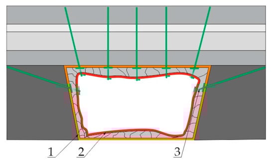
Figure 1.
Holding the rocks up by the rock bolt support when serious deformations appear: 1—original shape of the room; 2—shape of the room after rock mass deformation; 3—yieldable rock bolt support.
Currently, more and more new concepts of the rock bolt support are being developed, the common feature of which is the ability to maintain high load capacity of the support while accepting much greater displacements and deformations of the support. Among the special designs of rock bolt supports we can distinguish those which are characterized by variable geometry along their length. Ortlepp et al. [24] examined the Duracable cable bolt, which had the shape of a sine wave. St-Pierre et al. [25] proposed a sliding effect for the Modified Cone Bolt, which was widened at the bottom of the opening. Li [26] designed the D bolt, which is made of a smooth steel bar with numerous attachment points in the opening, between which bolt sections of variable diameter are present. They are also subject to extension. Displacements of the rock bolt support are a result of deformations of the bolt material in terms of elasticity and plasticity, as well as the properties of the applied binding materials (cement, adhesive) and the specific construction and applied mechanisms of the so-called energy absorbers. A frequent way to make the rock bolt support more yieldable is to use an additional element inside the bolt hole. Wu and Oldsen [27] used a profiled conical polymer cover, which was placed on the Y-lok rock bolt at the bottom of the hole. Charette and Plouffe [28] tested the Roofex bolt, which was equipped with a steel absorber inside the hole between the two sleeves. Varden et al. [29] examined the Garford bolt equipped with a sliding bolting mechanism that is pressed against the bolt below the mixing section. During the rock mass deformation, the bolt is pressed through the construction, which causes its extension. The mechanism of bolt pulling through the steel absorber firmly fixed inside the bolt hole was also tested by Wanga [30]. He et al. [31,32] examined the He bolt equipped with an energy absorber and a steel pipe. Using a sliding pipe inside the hole, the total displacement of the bolt can be up to 1 m. Wu et al. [33] proposed a new solution for the rock bolt, a tension and compression-coupled (TCC) yieldable support. A section of the rock bolt in the hole can be fixed either with the use of cement binder or the adhesive. The characteristic features of the bolt are two additional attachment points inside the hole, between which there is a smooth steel bar not connected or very poorly connected to the binder, which is stretched during rock mass deformation. Bolts of the length of 2.5 to 5 m can be extended from 386 to 754 mm. One of the elements of the rock bolt support can also be an element responsible for making it yieldable, which is placed on the rock bolt. It is located between the bearing plate and the bolt nut. Lu et al. [34] and Sun et al. [35] proposed a way of making the support yieldable with the use of a steel cylinder, which is deformed under load, increasing its diameter. Korzeniowski et al. [36] made the extension rock bolt support more yieldable by using two disc springs, which were placed between the two bearing plates. As a result of different levels of stiffness of construction materials and geometry, the bearing plate was deformed under load and directed inside the hole of disc springs. Chen et al. [37] examined the R bolt, which was additionally equipped with a rubber bearing plate of 50 mm diameter and 25 mm height. Due to such a solution, the support is able to absorb energy several times during dynamic loads. A very interesting and innovative solution was presented by Dai et al. [38], whose idea to make the support more yieldable was to do it with the use of a divided sleeve with wall thickness of 2 to 4 mm and length of 150 mm, which is divided into four irregular parts under load. The sleeve serves as both an element making the support yieldable and a load indicator. The use of such a solution results in the fact that it can be included in the nondestructive methods for determining the load of the rock bolt support in industrial conditions [39,40,41]. These yieldable forms cause the rock bolt to deform in the range of several dozen to several hundred millimeters. In the underground copper mines in the Legnica-Głogów Copper District in Poland, rock bolts are installed by means of resin cartridges on the full column. On the other hand, there are no resin rock bolts installed partially with a yieldable support in the form of a dome bearing plate. According to the authors, this solution may contribute to changing the technology of installing the resin rock bolts by significantly reducing the number of resin cartridges. Additionally, yieldable rock bolts installed segmentally directly extend the functionality of the excavation in the event of a sudden, unexpected fall of roof rocks. Considering the lack of information in the literature regarding the increase in the scope of work, through the use of a bearing plate for segmentally embedded resin rock bolts, we investigated the yieldable rock bolts, which were installed in the rock mass model for three different embedment lengths in order to determine the load–displacement characteristics, which were then compared with nonyieldable rock bolts.
2. Characteristics of the Room and Pillar Methods with Mined Roof Bending
2.1. Characteristics of Geological Conditions in the Areas of Ore Deposits in the Polkowice-Sieroszowice Mine
The copper ore deposits exploited in the Legnica-Głogów Copper Belt by the underground mine Polkowice-Sieroszowice owned by KGHM Polska Miedź S.A. have the form of an irregular pseudoseam and fall at an angle from 1 to 6° in the northeast. The deposit is located at a depth of 670.2 to 1385 m in the Głogów Głęboki Przemysłowy mining area. Copper minerals are found in three main lithological forms of rocks. The different types of copper are sandstone, shale and carbonate. Carbonate and shale ores dominate, accounting for over 77% of the extracted ore on the surface; the remaining 23% is sandstone ore. In these ores, the most common are four basic copper sulphates: chalcocite, bornite, chalcopyrite and covellite. The deposit belongs to the type of sediment-hosted copper deposit occurring in sedimentary rocks of varied thickness reaching several meters. In the deposit series, there are fault zones with discharges reaching several dozen meters. Copper ore is a polymetallic ore. In addition to copper, the second important metal is silver, with a content ranging from 44 to 78 g/Mg of ore. In 2018, the mine extracted over 196,000 Mg of copper, over 300,000 Mg of rock salt and over 0.428 Mg of silver. The current production capacity of ZG Polkowice-Sieroszowice is approximately 12 million Mg of ore per year [42]. A part of the copper ore deposit is characterized by a small thickness, much smaller than the height of mining excavations. The ore with a thickness of up to 1.5 m is considered to be of low thickness in the conditions of the Polkowice-Sieroszowice mine. Rational exploitation of such a deposit forces the use of the method of separating mining in mining faces, dividing the waste rock from the balance ore and locating it in the postmining voids. The machinery is also adjusted to the parameters of the exploited deposit, mainly to its thickness. Drilling, bolting, blasting, loading and hauling trucks range from 1.4 to 2 m high (Figure 2). Immediate and main roofs are made of carbonate Zechstein rocks which reach the thickness of over 100 m in the Polkowice-Sieroszowice mine. The average thickness of the Zechstein carbonate series is about 20 m (from 7 to 40 m) in the area of deposits of low thickness. Porosity and caverning of gypsum and anhydrite mountings, as well as numerous dikes and fractures filled with these minerals, have a significant influence on strength, deformation and structural parameters.
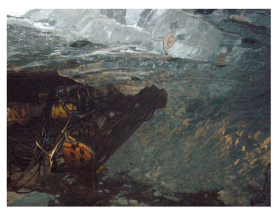
Figure 2.
Deposit exploitation below 2 m (visible stratification of the roof rocks).
In the interval of about 5 to 11 m above the excavation roof there is a layer of limestone dolomites, which are strongly porous and cavernous, weakly compact, brittle and easily loose, often waterlogged, with significantly reduced strength parameters. It lacks a clear bedding separation. At the deposit level (in the extraction gate), apart from copper-bearing shales, there are also clay, streaked and limestone dolomites. In addition to joint fractures, there are also numerous vertical fractures and single, flatly inclined tectonic slides with an inclination of 10 to 30°. Grey sandstones of the Rotliegend with a thickness of up to 24 m can be found in the immediate floor. These are fine-grained, quartz, compact and semicompact sandstones with a carbon, clayey-carbon, clay, or, occasionally, siliceous and sulfurous binder.
2.2. Room and Pillar Method with Mined Roof Bending
Currently, for the extraction of thin deposits below 3 m, the room and pillar method with mined roof bending is used. The system can be used for the selection of deposits lying under roofs of high strength parameters (compression strength above 70 MPa) and when the roof reinforced by rock bolts shows a tendency to bend without the occurrence of collapsing in the strip covered by the extraction works. The inclination angle of the deposit can be up to 8°. The ore mineralization varies both in the roof and floor parts. Therefore, there is some discretion over the adjustment of the mined deposit height. By choosing a reduced height of the mined deposit, the ore with a higher metal content is obtained but with higher losses; with higher mined deposit, the ore is adequately depleted but the metal loss is lower. The idea of the room and pillar method with roof bending is to divide the deposit by introducing rooms and retaining pillars placed between the rooms of such dimensions, which will allow for the destruction of the pillars at the front of the excavation in a postcritical phase. The pillars work on the postdestructive (falling) stress–strain characteristics and allow for room deflection. Roof collapse occurs further away from the front of the excavation, inside the goaf (Figure 3). As the mining front progresses, the technological pillars on the liquidation line are cut in the goaf, where they act as supports to alleviate the curvature of the bending roof layers. Residual pillar resistance is selected in such a way as to secure the stability of the roof in the liquidation area, at the same time enabling its gentle deflection. The cross-section area of the residual pillars at the junction with the roof should not be less than 12 m2. The length of the front of the excavation works can vary from 100 to 600 m. The opening width of the working space is the distance from the cutting line to the goaf line, calculated on the basis of the stiffness indicator of the pillars, M, which takes into account the average resistance to uniaxial compression of the rocks of the mined deposit, and the width and height of the technological pillars. The length of the mining front and the excavation field are determined in relation to the existing geological and mining situation, taking into account, among other things, faults, old goaf and planned mining. In a deposit with a thickness of less than 3 m, the deposit is selected with rooms with a width of up to 6 m, driven into the full thickness of the deposit, separating technological pillars with a geometry of 6 m in width and 8 m in length. The pillars are situated on the long side perpendicularly to the front line. A leakage of the mining front in the field and the order in which the pillars are selected are shown in Figure 4. In the strip where excavation works are carried out, there are three stages of work which can be distinguished. The first stage consists of mining excavations (rooms, strips perpendicularly to rooms) at the exploitation front, in accordance with the geometry of the adopted exploitation system. In practice, this means the separation of technological pillars, which enter the state of postdestructive work. The rooms and strips are trapezoidal in shape and are generally 6 m wide at the roof. The sidewalls of the rooms and strips are inclined towards the unmined coal by an angle of 10°. In the first stage of the cutting works (Figure 4), there are generally no difficulties in maintaining their stability. Instability, mainly of the sidewalls, may occur in the case of high-energy rock mass tremors located at the front of the exploitation or near it. The second stage (Figure 4) is a developed exploitation, which includes a strip of uncovered roof and floor with mined rooms and strips between the line of the exploitation front and the last row of pillars on the goaf side. At the stage of developed exploitation, as the front moves, the pillars are crushed, the sidewalls creep and the span of the rooms is changed. The increasing susceptibility of the crushed pillars benefits the formation of block structures in the bending roof, especially at crossroads. In order to maintain the proper width of the rooms and the inclination of the sidewalls, cutting of the sidewalls is used. Spontaneously falling sidewalls can cause local extensions to the excavation sites. Similar phenomena may occur during the cutting of the sidewalls. Additional bolts are installed at the extension points; in case of observed instability, additional roof reinforcement is used, such as long bolting, hydraulic props, wooden props and wooden cribs. The third stage is implemented in the last row of technological pillars. At this stage, the last row of technological pillars is cut and the residual pillars with minimum dimensions remain to guarantee maximum utilization of the deposit and safe working conditions. At the stage of liquidation works, the largest exposure of the roof is obtained, followed by an increased the risk of roof collapse. Liquidation works must be carried out in the shortest possible time, because the rock mass is already fractured and the rooms are widened. After the selection cycle is completed, the postexcavation space is liquidated, which consists of fencing a selected part of the deposit with wooden cribs or props and automatic transition to the state of collapse at a further distance from the goaf line. Residual pillars are left on the goaf line with a cross-section area of 12 to 20 m2 at the roof, in order to reduce deflection (collapse) of the roof and ensure the required load capacity of the goaf.
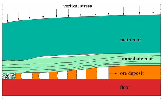
Figure 3.
Scheme of roof bending on pillars.
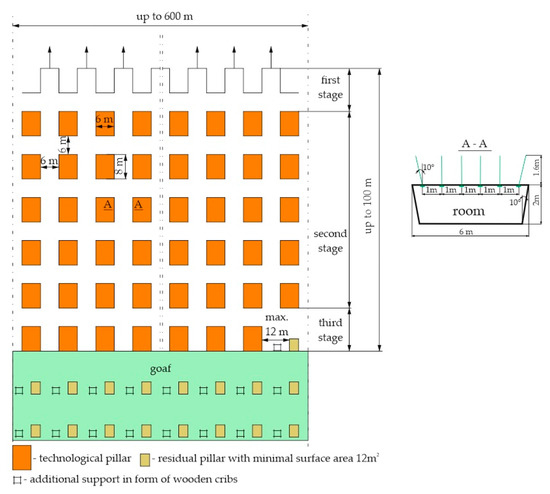
Figure 4.
Leakage of the mining front in the field and the order in which the pillars are selected.
2.3. Roof Reinforcement with Rock Bolt Support
The behavior of the rock mass as a result of mining is very diverse, because mining works in most excavations are carried out in a stratified rock mass, consisting of a system of rock layers of different thicknesses and different strength and deformation properties. The choice of a specific theory describing the cooperation of the bolt support with the rock mass is a complex issue which takes into account geological, mining, technical and technological factors that occur within the exploitation excavation. In the case of a stratified roof, the combination of several rock layers contributes to an increase in the resistance moment, which is a measure of resistance of a given layer to the pressure of the rock mass. According to Panek [43], bolting causes the reinforcement of the roof, which results from friction and suspension. Friction occurs as a result of rock bolts being subjected to preload. By compressing the individual layers, the bolts create friction between the layers, which resist the displacement of the layers against each other. The effect of suspension is to transfer a part of the weight of the immediate roof layers to the thicker main roof layers deposited above. It occurs when rock layers with different bending properties are forced to bend together. If all the layers of a bolted series of rock layers have the same amount of deflection, only friction occurs within the layers, without the effect of suspension. However, if not all the layers of the bolted series of rock layers have the same rigidity, then both friction and suspension occur. Assuming the model of cooperation of the rock bolt support with the rock mass, according to the theory of the rock beam building of roof layers (Figure 5a–c), it is possible to calculate the factor of roof reinforcement according to the formula:
where RF is reinforcement factor, and D is relative reduction of roof deflection [44], described as follows:
where n is number of bolts in a row, P is the bolt tension (N), h is the bolt length (m), t is the thickness of layers (m) γ is the volume weight of rocks (N/m3), b is the distance between bolts (m), L is the roof span (m) and E is modulus of elasticity of rocks (Pa).
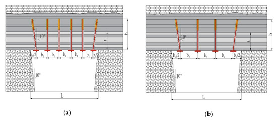
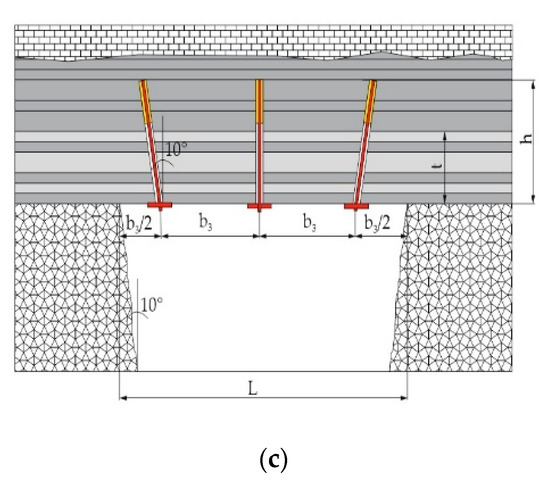
Figure 5.
Model of the rock beam building of roof layers: (a) rock bolt pattern 1 m × 1 m; (b) rock bolt pattern 1.5 m × 1.5 m; (c) rock bolt pattern 2 m × 2 m; L—span of the roof; t—thickness of the layers; h—length of bolts; b—distance between bolts; b1—spacing every 1 m; b2—spacing every 1.5 m; b3—spacing every 2 m.
Assuming the range of the rock damage zone in the roof of the room is 1.55 m, the bulk density of rocks located in this zone and assuming the three different rock bolt patterns of 1 m × 1 m, 1.5 m × 1.5 m and 2 m × 2 m, the loads per individual rock bolt were calculated (Table 1). Currently, in the geological and mining conditions at Legnica-Głogów Copper District mines in Poland, most of the installed rock bolts are 1.6 and 1.8 m long. In addition, the required length of the rock bolt support has been determined at 1.8 m, assuming that the support will be installed above the rock damage zone for as short a distance as possible. This length of the rock bolt support was accepted for further laboratory tests, in which the influence of the embedded length on the load–displacement characteristics of the segmentally installed rock bolt support was determined.

Table 1.
Summary of results of roof reinforcement with rock bolt support.
3. Materials and Methods
3.1. Segmentally Installed Resin Rock Bolt Support
Tensile laboratory tests of segmentally installed rock bolt support were carried out in the Department of Mining Engineering and Work Safety at the Faculty of Mining and Geoengineering of the AGH University of Science and Technology in Cracow. The rock bolt support consisted of a 1.8 m long ribbed bolt rod made of EPSTAL steel (grade B500SP), (Boltech Sp. z o.o., ZGH Bolesław S.A., Bukowno, Poland). It is a steel with increased ductility. The steel is characterized by yield limit Re in the range from 500 to 625 MPa and minimum A5 elongation of 16% [45]. The diameter of the bolt rod together with the ribs amounted to 22 mm. The height of the rib of the bolt rod was 1.35 mm; the width was 3.6 mm and the distances were 10, 18 and 20 mm. The bolt rod had an M20 thread on one side and a cut at the angle of 30° on the other side for better penetration of the resin cartridge. The bolt rod worked together with a steel, square, flat, profiled bearing plate with a sheet thickness of 6 mm and a side length of 145 mm. In order to make the support more yieldable, a round, dome bearing plate with a sheet thickness of 6 mm, a diameter of 150 mm and a height of 25.5 mm was used. The bearing plates were made of St3SAL steel (Figure 6a,c). A 34.3 mm high M20 nut made of steel grade St5 was screwed onto the threaded section of the bolt rod. The nut was equipped with a rod pin, for which the breaking moment was 40 N m (Figure 6b,d).
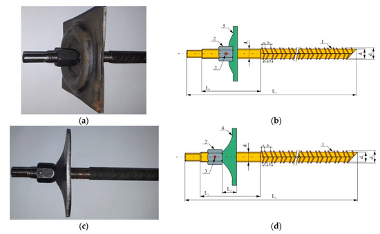
Figure 6.
Rock bolt support: (a) general view with flat bearing plate; (b) bolt with flat bearing plate with elements; (c) general view with dome bearing plate; (d) bolt with dome bearing plate with elements; 1—ribbed bolt rod; 2—M20 nut; 3—rod pin; 4—dome, round bearing plate; 5—profiled, flat, square bearing plate; L1—M20 thread length of the bolt rod (111 mm); L2—height of the dome bearing plate (25.5 mm); L3—length of the bolt rod (1.8 m); d1—diameter of the bold rod in the threaded part (19.2 mm); d2—diameter of the bolt rod core (19.5 mm); d3—diameter of the bolt rod with ribs (22 mm); a,b,c—distances between ribs of 10, 18 and 20 mm, respectively.
3.2. The Model of the Rock Mass
In the laboratory tests, the rock mass was simulated with cylindrical concrete blocks made of a concrete mix, which in the required period reached a compressive strength of 50 MPa. The cylinders had a diameter of 100 mm. Compressive strength tests of concrete were carried out on regular cubic samples with a side length of 150 mm. After 28 days from the completion of molding, nondestructive testing with a Schmidt hammer (Figure 7a–b) was applied. After 28 days from filling the steel cylinders, holes were made with a diameter of 28 mm (Figure 8) using a hand hammer drill equipped with a trepan. Subsequently, the rock bolt support, which has been installed at the lengths of 100, 150 and 200 mm, was inserted, in order to determine the minimum embedded length for which the rock bolt support operates within its full load range (Figure 9). Multicomponent resin cartridges [46] with a length of 450 mm and a diameter of 24 mm (Figure 10) were used to clamp bolts in the holes. The resin cartridges were characterized by a curing time of 10 min. In order to check the uniaxial compression strength of the resin, 50 cylindrical samples with a diameter and height of 50 mm were made in the laboratory (Figure 11a). The samples were compressed on a testing machine with a load rate of 0.1 kN/s (Figure 11b). The average value of compressive strength was 45.2 MPa.
Figure 7.
Nondestructive testing of the compression strength of cubic concrete blocks with a Schmidt hammer: (a) test material; (b) view during the test.
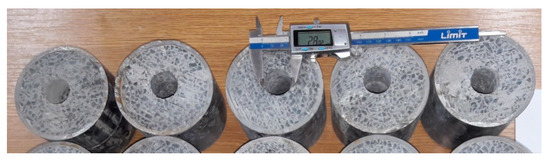
Figure 8.
Cylinders filled with concrete mixture with holes with a diameter of 28 mm.
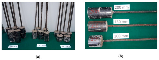
Figure 9.
Bolts installed on the lengths of 100, 150 and 200 mm: (a) general view; (b) detailed view.
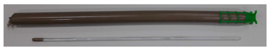
Figure 10.
Resin cartridge with a glass ampoule filled with the initiator of the polymerization process.
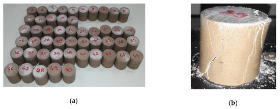
Figure 11.
Cylindrical samples: (a) general view; (b) sample after compression test.
3.3. Load–Displacement Characteristics of a Segmentally Installed Rock Bolt Support
The segmentally installed rock bolt support was subjected to tensile testing on a testing machine in the bolt laboratory of the Department of Mining Engineering and Work Safety (Figure 12a,b). The laboratory station is designed for strength testing of rock bolt support units in 1:1 geometric scale, for bolt rods up to 6 m long under static and quasistatic load. The system is powered by a hydraulic power supply unit based on a piston pump with variable capacity and constant power and constant pressure regulators. The maximum supply pressure is 31 MPa. The maximum value of the tensile load is 1600 kN [47]. The diameter of the bolt hole is 28 mm. The choice of this diameter corresponded to the technology of bolting in industrial conditions. For this hole diameter, five bolts were tested for the lengths of 100, 150 and 200 mm with a bearing plate. In addition, for the length of 200 mm, five bolts with a flat bearing plate were tested. Four stress–strain gauge sensors were used to measure the load, while a wire-draw encoder was used to measure displacement. The sensors were connected to a universal measuring amplifier Quantum MX840A, (HBM, Spectris plc, Darmstadt, Germany) which in turn was connected to a computer. The load rate amounted to 0.5 kN/s. The results of the measurements were recorded as they occurred using the Catman-Easy software. The results of the tensile tests of the rock bolt support unit, fixed on the 100, 150, and 200 mm segments for the 28 mm hole diameter with a flat bearing plate and dome are presented in Figure 13a–h and in Table 2.
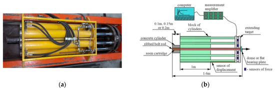
Figure 12.
Diagram of bolt fixing at the laboratory test station: (a) general view; (b) block diagram.
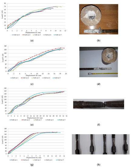
Figure 13.
The load–displacement characteristics of the segmentally installed rock bolt support for the diameter of 28 mm, with a dome bearing plate (a) at the length of 100 mm; (b) bolt extension for the grouted length of 100 mm; (c) 150 mm; (d) bolt extension for grouted length of 150 mm; (e) 200 mm; (f) bolt breakage at the thread for the grouted length of 200 mm; (g) 200 mm with a flat bearing plate; (h) bolt breakage at the thread for the grouted length of 200 mm with a flat bearing plate.
Table 2.
Summary of the results of the influence of the length of mounting on the load capacity of the rock bolt support.
4. Discussion of Results
The work (energy used for deformation and displacement) performed by the rock bolt support unit under laboratory conditions corresponds to the surface area under the curve y = f(x) in the force displacement diagram. The value of the marked integral can be obtained by replacing the curve y = f(x) with a system of parabolic arches (Figure 14). This method leads to Simpson’s formula [48]. The results of the amount of energy absorbed by the rock bolt support with a flat bearing plate and a dome bearing plate are shown in Figure 15a–h. In addition, Figure 16 shows the deformation of the dome bearing plate (right) after the tensile test of the rock bolt support.
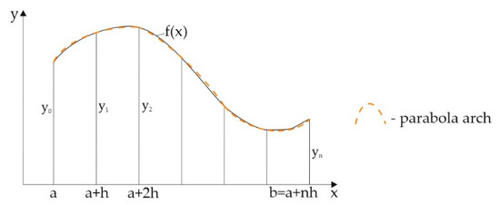
Figure 14.
Evaluation of the integral using the Simpson formula.
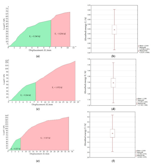
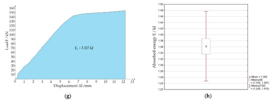
Figure 15.
Average amount of energy absorbed by the rock bolt support: (a) grouted on the length of 100 mm with a dome bearing plate; (b) absorbed energy for 100 mm; (c) grouted on the length of 150 mm with a dome bearing plate; (d) absorbed energy for 150 mm; (e) grouted on the length of 200 mm with a dome bearing plate; (f) absorbed energy for 200 mm; (g) grouted on the length of 200 mm with a flat bearing plate, (h) absorbed energy for 200 mm; E1—energy absorbed by the support without plastic deformation of the bearing plate; E2—energy absorbed by a bolt; E3—energy absorbed by a bolt with a flat bearing plate.
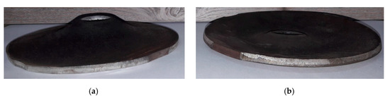
Figure 16.
The dome bearing plate: (a) before the test; (b) after the tensile test.
For example, let us consider a part of the curve in the range a ≤ x ≤ a + 2h and mark the ordinates corresponding to a, a + h and a + 2h by y0, y1 and y2. The equation of any parabola passing through point (a + h, y1) takes the following form:
Let us determine two constants α and β in such a way that the curve also passes through points (a,y0) and (a + 2h, y2). The result is:
The area between this parabolic arch and the x-axis is:
Each parabolic arch covers a range of 2h, and if we divide the segment ab into an even number n of equal ranges h, we can approximate the whole curve y = f(x) from a to b by means of a series of parabolic arches. The area representing the integral is then approximated by the sum of all the areas under these parabolic arches:
Comparing the curves of the load–displacement characteristics of the segmentally installed rock bolt support at the length of 200 mm, it can be noticed that the value of the breaking force without making the rock bolt more yieldable was in the range from 150 to 155 kN. Very similar results were obtained for the yieldable rock bolt, for which the breaking force ranged from 149 to 157 kN. The course of plastic deformation of a yieldable rock bolt is fundamentally different from that of nonyieldable rock bolt. Using a deforming, profiled bolt bearing plate makes the rock bolt support more yieldable and results in a total displacement (extension of the bolt rod and plastic deformation of the profiled dome bolt bearing plate) of 32.67 mm. This represents a displacement increase of 317% compared to rock bolt support unit with a flat bearing plate. On the basis of Figure 15, it can be concluded that the amounts of energy absorbed by the rock bolt supports with the dome bearing plates fixed at 100, 150 and 200 mm are 0.444, 1.296 and 3.554 kJ, respectively. However, for the rock bolt support unit with a flat bearing plate, installed in the 200 mm segment, the amount of absorbed energy is 1.362 kJ. The load–displacement characteristics were obtained for the grouted length of 200 mm, for which the breakage of the material occurred on the bolt rod. The amount of energy absorbed by the rock bolt equipped with a dome bearing plate is by 260% higher than that of the rock bolt equipped with a flat bearing plate. The total energy absorbed by the rock bolt support with the dome bearing plate consists of the plastic deformation of both the bolt bearing plate and the bolt rod. The amount of energy absorbed by such a bolt is very small, which limits its use in dynamic hazard conditions. The bolt bearing plates, both flat and dome, were not damaged under maximum load. For the rock bolt support, the weakest structural point is the thread, for which the continuity of the material was interrupted.
5. Conclusions
One of the conditions for safe exploitation of ore deposits by the room and pillar method with roof deflection is the possibility of maintaining certain geometric parameters of the room excavation over a certain period of time. In this case, the stability of room excavation can be significantly improved by using a yieldable rock bolt support. In conditions of significant deformation of roof beds, a yieldable element of rock bolt should be used, which makes the rock bolt more yieldable.
For the 2 m high and 6 m wide room, in which six bolts with 1 m × 1 m spacing is used, the roof reinforcement coefficient is the best and amounts to 2.404, whereas the weakest result was obtained for three bolts with 2 m × 2 m spacing, where the reinforcement coefficient was 1.487.
In laboratory conditions, it was experimentally determined that the minimum embedded length for a 22 mm diameter ribbed bolt rod was 200 mm. The maximum values of load taken over by the rock bolts grouted in the 100, 150, and 200 mm segments of concrete are 66.45, 123.49 and 153.97 kN, respectively. However, the support worked in the full range of load and displacement characteristics only for an installation length of 200 mm. For shorter grouted lengths, the bolt rod was extended from the bolt hole. Comparing the results of numerical tests with laboratory tests, it should be stated that the maximum spacing of the rock bolt support is 1.5 m × 1.5 m. For spacing of 2 m × 2 m, the load per bolt is 20 kN higher than the maximum load capacity of the single rock bolt.
On the basis of laboratory tests, it was found that the use of profiled dome bearing plates may be a form of making the segmentally installed rock bolt more yieldable by means of its plastic deformation. A 1.8 m long bolt grouted at the length of 200 mm with a dome bearing plate allows to absorb 3.554 kJ of energy, thanks to the possibility of performing additional work. This is 2.6 times the energy absorbed by the bolt with the flat bearing plate, which absorbs only 1.362 kJ. In order to reduce the effects of the impact of the rock mass on the deformation of rock bolts, they should be equipped with appropriately selected elements designed to make them more yieldable and limit the effects of the load. The applied profiled dome bearing plate was characterized by a reduction in height by 22 mm. It can be concluded that the higher the height of the dome bearing plate, the higher the amount of energy absorbed. However, in case of low mining excavations below 2 m, where blasting, bolting and loading jumbos are used, it is recommended that the bearing plates should be flat, so that they do not hinder the movement of the vehicles. Further laboratory tests should be focused on the use of construction materials that will allow for the thinning of the rock bolt support in industrial conditions while maintaining as much of the absorbed energy as possible.
Author Contributions
Conceptualization, K.S., W.K., and K.Z.; methodology, K.S., W.K., and K.Z.; software, K.S.; validation, K.S., W.K.; formal analysis, K.S., W.K., K.Z., and A.Z.; investigation, K.S., W.K., K.Z., and A.Z.; resources, K.S., W.K., and K.Z.; writing—original draft preparation, K.S., W.K., and K.Z.; writing—review and editing, K.S., W.K., and K.Z.; visualization, K.S. and A.Z.; supervision, K.S., W.K. All authors have read and agreed to the published version of the manuscript.
Funding
This paper was written under grant entitled “The Self-Excited Acoustic System (SAS) for Monitoring Safety Levels in Mine Workings”. Agreement No. TANGO2/340166/NCBR/2017. This article was also prepared as part of AGH’s scientific subsidy, under No. 16.16.100.215.
Conflicts of Interest
The authors wish to confirm that there are no known conflicts of interest associated with this publication and there has been no significant financial support for this work that could have influenced its outcome.
References
- Cai, M. Principles of rock support in burst-prone ground. Tunn. Undergr. Space Technol. 2013, 36, 46–56. [Google Scholar] [CrossRef]
- Li, C.C.; Stjern, G.; Myrvang, A. A review on the performance of conventional and energy-absorbing rockbolts. J. Rock Mech. Geotech. Eng. 2014, 6, 315–327. [Google Scholar] [CrossRef]
- Chen, L.; Sheng, G.; Chen, G. Investigation of impact dynamics of roof bolting with passive friction control. Int. J. Rock Mech. Min. Sci. 2014, 70, 559–568. [Google Scholar] [CrossRef]
- Małkowski, P. The impact of the physical model selection and rock mass stratification on the results of numerical calculations of the state of rock mass deformation around the roadways. Tunn. Undergr. Space Technol. 2015, 50, 365–375. [Google Scholar] [CrossRef]
- Małkowski, P.; Niedbalski, Z.; Majcherczyk, T. Roadway design efficiency indices for hard coal mines. Acta Geodyn. Geomater. 2016, 13, 201–211. [Google Scholar] [CrossRef]
- Skrzypkowski, K. Evaluation of Rock Bolt Support for Polish Hard Rock Mines. In E3S Web of Conferences; EDP Sciences: Les Ulis, France, 2018; Volume 35, p. 01006. [Google Scholar] [CrossRef]
- Thenevin, I.; Blanco-Martín, L.; Hadj-Hassen, F.; Schleifer, J.; Lubosik, Z.; Wrana, A. Laboratory pull out tests on fully grouted rock bolts and cable bolts: Results and lessons learned. J. Rock Mech. Geotech. Eng. 2017, 9, 843–855. [Google Scholar] [CrossRef]
- Pytlik, A.; Prusek, S.; Masny, W. A methodology for laboratory testing of rock bolts used in underground mines under dynamic loading conditions. J. S. Afr. Inst. Min. Metall. 2016, 116, 1101–1110. [Google Scholar] [CrossRef]
- Skrzypkowski, K. The influence of room and pillar method geometry on the deposit utilization rate and rock bolt load. Energies 2019, 12, 4770. [Google Scholar] [CrossRef]
- Bierman, I.R.; Gardner, L.; Piper, P. An evaluation of the bond strength of multiple resin bolt and capsule combinations through laboratory testing and applied methodologies. In Proceedings of the Ninth International Conference on Deep and High Stress Mining, Johannesburg, South Africa, 24–25 June 2019; Joughin, W., Ed.; The Southern African Institute of Mining and Metallurgy: Johannesburg, South Africa, 2019; pp. 175–190. [Google Scholar] [CrossRef]
- Villaescusa, E.; Varden, R.; Hassell, R. Quantifying the performance of resin anchored rock bolts in the Australian underground hard rock mining industry. Int. J. Rock Mech. Min. Sci. 2008, 45, 94–102. [Google Scholar] [CrossRef]
- Li, C.C.; Kristjansson, G.; Høien, A.H. Critical embedment length and bond strength of fully encapsulated rebar rockbolts. Tunn. Undergr. Space Technol. 2016, 59, 16–23. [Google Scholar] [CrossRef]
- Feng, X.; Zhang, N.; Li, G.; Guo, G. Pullout Test on Fully Grouted Bolt Sheathed by Different Length of Segmented Steel Tubes. Shock Vib. 2017, 2017, 4304190. [Google Scholar] [CrossRef]
- Ma, C.; Wang, P.; Jiang, L.; Wang, C. Deformation and Control Countermeasure of Surrounding Rocks for Water-Dripping Roadway Below a Contiguous Seam Goaf. Processes 2018, 6, 77. [Google Scholar] [CrossRef]
- Skrzypkowski, K.; Korzeniowski, W.; Zagórski, K.; Zagórska, A. Flexibility and load-bearing capacity of roof bolting as functions of mounting depth and hole diameter. Energies 2019, 12, 3754. [Google Scholar] [CrossRef]
- Aziz, N.; Jalalifar, H. The role of profile configuration on load transfer mechanism of bolt for effective support. J. Mines Met. Fuels 2007, 55, 539–545. [Google Scholar]
- Tao, W.; Chen, C.; Jun, H.; Ting, R. Effect of bolt rib spacing on load transfer mechanism. Int. J. Min. Sci. Technol. 2017, 27, 431–434. [Google Scholar] [CrossRef]
- Ghadimi, M. Effect of profile bolt in bond strength fully grouted rock bolts using analytical and experimental methods. Int. J. Min. Miner. Eng. 2017, 8, 156–167. [Google Scholar] [CrossRef]
- Yokota, Y.; Zhao, Z.; Shanga, J.; Nie, W.; Date, K.; Iwano, K.; Okada, Y. Effect of bolt configuration on the interface behaviour between a rock bolt and bond material: A comprehensive DDA investigation. Comput. Geotech. 2019, 105, 116–128. [Google Scholar] [CrossRef]
- Skrzypkowski, K.; Korzeniowski, W.; Zagórski, K.; Dudek, P. Application of Long Expansion Rock Bolt Support in the Underground Mines of Legnica–Głogów Copper District. Stud. Geotech. Mech. 2017, 39, 47–57. [Google Scholar] [CrossRef]
- Skrzypkowski, K. Laboratory testing of a long expansion rock bolt support for energy-absorbing applications. In E3S Web of Conferences; EDP Sciences: Les Ulis, France, 2018; Volume 29, p. 00004. [Google Scholar] [CrossRef]
- Skrzypkowski, K. A new design of support for burst-prone rock mass in underground ore mining. In E3S Web Conferences; EDP Sciences: Les Ulis, France, 2018; Volume 71, p. 00006. [Google Scholar] [CrossRef]
- Cai, M.; Champaigne, D.; Coulombe, J.G.; Challagulla, K. Development of two new rockbolts for safe and rapid tunneling in burst-prone ground. Tunn. Undergr. Space Technol. 2019, 91, 103010. [Google Scholar] [CrossRef]
- Ortlepp, W.D.; Human, L.; Erasmus, P.N.; Dawe, S. Static and Dynamic Load Displacement Characteristics of a Yielding Cable Anchor—Determined in a Novel Testing Device. In Proceedings of the Sixth International Symposium on Rockburst and Seismicity in Mines Proceedings, Perth, Australia, 9–11 March 2005; Potvin, Y., Hudyma, M., Eds.; Australian Centre for Geomechanics: Perth, Australia, 2005; pp. 529–534. [Google Scholar]
- St-Pierre, L.; Hassani, F.P.; Radziszewski, P.H.; Oullet, J. Development of a dynamic model for a cone bolt. Int. J. Rock Mech. Min. 2009, 46, 107–114. [Google Scholar] [CrossRef]
- Li, C.C. A new energy-absorbing bolt for rock support in high stress rock masses. Int. J. Rock Mech. Min. Sci. 2010, 47, 396–404. [Google Scholar] [CrossRef]
- Wu, Y.K.; Oldsen, J. Development of a new yielding rock bolt—Yield-Lok bolt. In Proceedings of the 44th US Rock Mechanics Symposium and 5th US-Canada Rock Mechanics Symposium, Salt Lake City, UT, USA, 27–30 June 2010; American Rock Mechanics Association: Alexandria, VA, USA, 2010; pp. 1–6. [Google Scholar]
- Charette, F.; Plouffe, M. Roofex®—Results of Laboratory Testing of a New Concept of Yieldable Tendon. In Proceedings of the 4th International Seminar on Deep and High Stress Mining, Perth, Australia, 7–9 November 2007; Potvin, Y., Ed.; Australian Centre for Geomechanics: Perth, Australia, 2007; pp. 395–404. [Google Scholar]
- Varden, R.; Lachenicht, R.; Player, J.; Thompson, A.; Villaescusa, E. Development and implementation of the Garford Dynamic Bolt at the Kanowna Belle Mine. In Proceedings of the 10th Underground Operators’ Conference—Boom and Beyond, Tasmania, Australia, 14–16 April 2008; The Australasian Institute of Mining and Metallurgy, Ed.; The Australasian Institute of Mining and Metallurgy Launceston: Tasmania, Australia, 2008; pp. 95–104. [Google Scholar]
- Wang, G.; Wu, X.; Jiang, Y.; Huang, N.; Wang, S. Quasi-static laboratory testing of a new rock bolt for energy-absorbing applications. Tunn. Undergr. Space Technol. 2013, 38, 122–128. [Google Scholar] [CrossRef]
- He, M.; Gong, W.; Wang, J.; Qi, P.; Tao, Z.; Du, S.; Peng, Y. Development of a novel energy-absorbing bolt with extraordinarily large elongation and constant resistance. Int. J. Rock Mech. Min. Sci. 2014, 67, 29–42. [Google Scholar] [CrossRef]
- He, M.; Gao, Y.; Yang, J.; Gong, W. An Innovative Approach for Gob-Side Entry Retaining in Thick Coal Seam Longwall Mining. Energies 2017, 10, 1785. [Google Scholar] [CrossRef]
- Wu, X.; Jiang, Y.; Wang, G.; Gong, B.; Guan, Z.; Deng, T. Performance of a New Yielding Rock Bolt Under Pull and Shear Loading Conditions. Rock Mech. Rock Eng. 2019, 52, 3401–3412. [Google Scholar] [CrossRef]
- Lu, Y.; Wang, L.; Zhang, B. An experimental study of a yielding support for roadways constructed in deep broken soft rock under high stress. Min. Sci. Technol. 2011, 21, 839–844. [Google Scholar] [CrossRef]
- Sun, X.; Wang, L.; Lu, Y.; Jiang, B.; Li, Z.; Zhang, J. A yielding bolt—Grouting support design for a soft-rock roadway under high stress; a case study of the Yuandian No. 2 coal mine in China. J. S. Afr. Inst. Min. Metall. 2018, 118, 71–82. [Google Scholar] [CrossRef]
- Korzeniowski, W.; Skrzypkowski, K.; Zagórski, K. Reinforcement of Underground Excavation with Expansion Shell Rock Bolt Equipped with Deformable Component. Stud. Geotech. Mech. 2017, 39, 39–52. [Google Scholar] [CrossRef]
- Chen, L.; Li, Q.; Yang, J.; Qiao, L. Laboratory Testing on Energy Absorption of High-Damping Rubber in a New Bolt for Preventing Rockburst in Deep Hard Rock Mass. Shock Vib. 2018, 2018, 7214821. [Google Scholar] [CrossRef]
- Dai, L.; Pan, Y.; Wang, A. Study of the energy absorption performance of an axial splitting component for anchor bolts under static loading. Tunn. Undergr. Space Technol. 2018, 81, 176–186. [Google Scholar] [CrossRef]
- Sepehri, M.; Apel, D.; Szymanski, J. Full three-dimensional finite element analysis of the stress redistribution in mine structural pillar. J. Powder Metall. Min. 2013, 3, 1–7. [Google Scholar] [CrossRef]
- Niedbalski, Z.; Małkowski, P.; Majcherczyk, T. Monitoring of stand-and-roof-bolting support: Design optimization. Acta Geodyn. Geomater. 2013, 10, 215–226. [Google Scholar] [CrossRef]
- Skrzypkowski, K.; Korzeniowski, W.; Zagórski, K.; Dominik, K.; Lalik, K. Fast, non-destructive measurement of roof-bolt loads. Stud. Geotech. Mech. 2019, 41, 93–101. [Google Scholar] [CrossRef]
- KGHM POLSKA MIEDŹ S.A. Available online: https://kghm.com (accessed on 24 November 2019).
- Panek, L.A. Principles of Reinforcing Bedded Mine Roof with Bolts; Report of Investigations 5156; US Dept. of the Interior, Bureau of Mines: Washington, DC, USA, 1956.
- Pytel, W. Geomechanical Problems of Selecting the Rock Bolt Support for Mining Excavations; KGHM CUPRUM Sp. z o.o.—Research & Development Centre: Wrocław, Poland, 2012; p. 222. [Google Scholar]
- Epstal. Available online: http://epstal.pl/en/reinforcing-steel/properties (accessed on 30 November 2019).
- PRIG. Available online: https://prig-kleje.pl (accessed on 29 October 2019).
- Korzeniowski, W.; Skrzypkowski, K.; Herezy, Ł. Laboratory Method for Evaluating the Characteristics of Expansion Rock Bolts Subjected to Axial Tension. Arch. Min. Sci. 2015, 60, 210–224. [Google Scholar] [CrossRef]
- Karman, T.V.; Biot, M.A. Mathematical Methods in Engineering, 3rd ed.; State Scientific Publisher: Warszawa, Poland, 1958; p. 20. [Google Scholar]


© 2020 by the authors. Licensee MDPI, Basel, Switzerland. This article is an open access article distributed under the terms and conditions of the Creative Commons Attribution (CC BY) license (http://creativecommons.org/licenses/by/4.0/).