Abstract
In this paper, a folded spiral resonator with a double-layered structure for near-field wireless power transfer is proposed. In near-field wireless power transfer, conjugate impedance matching is important to achieve high transfer efficiency. To achieve maximum available efficiency, it is common to connect a matching circuit to the antenna. However, the loss increases if a matching circuit is used. A coupling inductor with a resonant capacitor has the capability to adjust an imaginary part of the input impedance, whereas the folded spiral resonator has the capability to adjust both the imaginary and real parts of the input impedance. This resonator can achieve the maximum available efficiency without a matching circuit. This paper shows that the folded spiral resonator with a double-layered structure realizes high transfer efficiency compared to conventional models.
1. Introduction
Recently, research on near-field wireless power transfer (WPT) has been increasingly active [1]. WPT technology can transmit power with no wired connection, which provides security and convenience for transmission. Due to these advantages, this technology is expected to be used in various applications, such as electronic devices [2], electric cars [3,4,5,6], and implanted medical devices [5,6,7,8,9,10,11].
The WPT system can be broadly classified into far-field systems, which transmit power via microwaves [12], and near-field systems [13], which utilize the coupling of antennas or coils. In the near-field system, the WPT systems are classified into two types: power-electronics-based systems [14,15,16,17] and high-frequency-based systems [18,19,20,21]. To understand the mechanism of near-field WPT, the coupled-mode-theory-based approach [22], the circuit-theory-based approach [23], and the field theory approach [24,25] are used. As a device to transfer power, coils [26,27,28,29] or antennas [30,31,32,33] are used. Therefore, there are various viewpoints from which to understand basic concepts of WPT [1].
To clarify the characteristics of our research, we categorize these near-field WPT systems. Firstly, we designate “coupler” as a device exchanging power between circuit and air. In this definition, the “coupler” includes a coupling coil and antenna. However, a “resonator” is not always included in a “coupler”; when the resonator comprises a coupling coil and a resonance capacitor, only the coupling coil is included in the “coupler”. To maximize power transmission [34], simultaneous conjugate matching both the transmitting (Tx) and receiving (Rx) side is necessary [35]. The real part of the impedance and the imaginary part of the impedance should be optimized in the WPT system. A “coupler” can be classified into three types:
- (a)
- Coupler with the capability of coupling:
The most widely used coupling coil in power-electronics based WPT systems [14,15,16,17] is classified into this type. For power factor compensation, a resonant capacitor is used, which plays the role of impedance matching of only the imaginary part. Thus, an impedance transformer or inverter circuit is required to adjust the real part of the impedance.
- (b)
- Coupler with the capability of coupling and imaginary-part impedance matching
Some types of self-resonant resonators, such as open-end spiral coils [36,37,38], are classified into this type. At the resonant frequency, the imaginary part of the impedance becomes zero. However, to achieve maximum transmission efficiency, an impedance conversion circuit to adjust the real part of the impedance is necessary.
- (c)
- Coupler with the capability of coupling and conjugate impedance matching
The WPT system proposed by MIT [13] utilizes a self-resonant open-end spiral coil and a one-turn loop coil. This structure has the capability of impedance matching of both the real and imaginary parts. Therefore, no additional matching circuit is required. The so-called “four-coil WPT system” [39,40,41,42] is also included in this type.
For wireless-communication systems, a folded dipole antenna [43] is commonly used because of the impedance matching function. A folded dipole antenna is also used for far-field WPT or energy harvesting systems [44,45]. However, this antenna is not appropriate for the use in near-field WPT because far-field radiation becomes an undesired emission in near-field WPT. A folded spiral resonator for near-field WPT with a single-layer structure has been proposed [46]. This resonator can adjust the input impedance of the real part by varying the conductor radius. Thus, the maximum available efficiency can be achieved without a matching circuit. However, the folded spiral antenna with a single-layered structure has a disadvantage in that the range of tunable impedance is limited since the pitch of the spiral structure limits the distance between the folded structure.
In this paper, a folded spiral resonator with a double-layered structure is proposed. Since two wires of a folded structure are wound in different planes for the double-layered structure, the folded distance can be determined independently of the spiral pitch. Furthermore, the double-layered structure reduces the proximity effect because the wire pitch is extended when compared to the single-layered structure. Furthermore, current distribution of the single-layered structure is not ideal because the inner conductor is interrupted between the outer conductor. By using a double-layered structure this problem is avoided. The effectiveness of the proposed resonator is compared with a conventional resonator.
2. Principle of the Folded Structure
Figure 1 shows the working principle of a folded dipole antenna for far-field communication. Compared to the dipole antenna, the folded dipole antenna has two wires: the radius of the outer wire, , and the radius of the inner wire, . The distance between the two wires (folded distance) is w. Let be the input impedance of the dipole antenna (i.e., without the inner wire). The input impedance of the folded dipole antenna is obtained by:
where vi is the current distribution ratio. The impedance amplification ratio 1/vi2 can be adjusted by changing the ratio of and . Moreover, when the radius of the two conductors are different, can also be adjusted by changing . Therefore, by changing , , and , the real part of the input impedance is adjustable.
Figure 1.
Folded-dipole structure.
A conventional folded dipole antenna radiates far-field emission, whereas a folded resonator for near-field WPT requires less far-field emission because it becomes an undesired emission. By adjusting the conductor radius or folded distance, a folded spiral resonator can achieve impedance matching.
Figure 2a shows a conventional spiral resonator used for near-field WPT. The radius of the wire is . The pitch of the spiral is . This resonator is used as a self-resonant resonator.
Figure 2.
Structures: (a) spiral resonator; (b) folded spiral resonator with a single-layered structure; (c) bird’s-eye view of the folded spiral resonator with a double-layered structure; (d) side view of the folded spiral resonator with a double-layered structure.
Figure 2b shows a folded spiral resonator with a single-layered structure. The folded principle shown in Figure 1 was applied to the conventional spiral resonator. The folded dipole antenna is intended to radiate far-field emission, and a folded spiral resonator is used in the near-field region because of its low-emission property. The radii of the outer and inner wires are . and respectively. The distance of the folded structure (i.e., between the outer and the inner wire) is . The pitch of the spiral structure is . In the single-layered structure, the outer and inner wires are wound in the same plane.
Figure 2c shows a folded spiral resonator with a double-layered structure (bird’s-eye view). A folded structure is applied to the spiral antenna in the vertical direction, thereby the distance between the wire elements is wider than the single-layered folded spiral resonator. Therefore, it is considered that the proximity effect of the double-layered folded spiral resonator can be reduced. Additionally, the single-layered structure has a problem in that the outer and the inner conductor lays in the same plane in turn. This causes a disturbance in current distribution. By using the double-layered structure, this problem can be avoided. The outer conductor is wound in the source layer, and the inner conductor is wound in the folded layer. Both ends of the spiral wire are connected by a shorting pin. Figure 2d shows a side view of the folded spiral resonator with a double-layered structure. The distance between the two layers (corresponding to the folded distance) is .
3. Simulation Models
To demonstrate the validity of the proposed structure, a method of moment (MoM) simulation using the commercial software FEKO was employed. Figure 3 shows the simulation model of the conventional spiral resonator, the folded spiral resonator with a single-layered structure, and the folded spiral resonator with a double-layered structure, respectively. The same structure was used for both transmitting (Tx) and receiving (Rx) resonators. The Tx resonator had Port 1 for feeding. The Rx resonator had Port 2 to connect the load. The source impedance and the load impedance were set to 50 Ω. The conductivity of copper (S/m) was used.
Figure 3.
Simulation models: (a) Spiral resonator; (b) Single-layered folded spiral resonator; (c) Double-layered folded spiral resonator.
The mechanical parameters of the resonators are described in Table 1. The inner radius , the number of turns N, the conductor radii , the folded distance , and the gap between spiral conductors were adjusted, thereby the transfer efficiency reached a maximum at 6.78 MHz by using a genetic algorithm. The outer radius of all resonators were set to . The transfer distance was set to . The conductors were composed of wires.

Table 1.
Design dimensions.
4. Results
4.1. Impedance Matching by the Folded Structure
To confirm impedance matching by adjusting the conductor radius, the input impedance and frequency characteristics are calculated when the inner conductor radius changes. The transfer distance D is set to 0.4 m.
The input impedance of the spiral resonator is shown in Figure 4a. The wire radius does not affect the real part of the input impedance. The input impedance of the folded spiral resonator with single-layered and double-layered structures is shown in Figure 4b,c, respectively. It is confirmed that the real part of the impedance is adjustable by changing the wire radius.
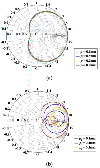
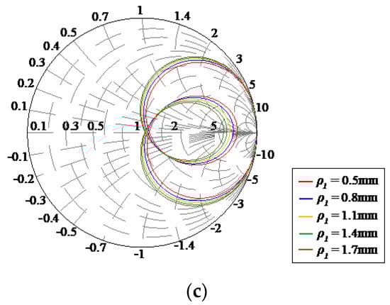
Figure 4.
Wire diameter characteristic of input impedance: (a) spiral resonator, (b) folded spiral resonator with a single-layered structure, and (c) folded spiral resonator with a double-layered structure.
The transfer efficiency is calculated as a function of the wire radius. Figure 5 shows the wire radius characteristics and maximum transfer efficiency at 6.78 MHz. corresponds to a transmission efficiency for 50 Ω load impedance. is obtained from the Z parameters through the S parameters [34].
where the matrix R is the real part of the Z parameter matrix, which is calculated from the S parameter matrix. |R| shows the determinant of the matrix R. From these results, it is found that the folded spiral resonator with a double-layered structure has the highest transmission efficiency.
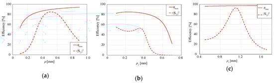
Figure 5.
Wire diameter characteristic of efficiency: (a) spiral resonator; (b) folded spiral resonator with the single-layered structure; (c) Folded spiral resonator with double-layered structure.
4.2. Comparison
In this section, the frequency characteristics of transmission efficiency are considered. Figure 6 shows the frequency characteristics of and . From the result, the folded spiral resonator with a double-layered structure has the highest and at 6.78 MHz.
Figure 6.
Frequency characteristics of transfer efficiency.
Figure 7 shows the transfer distance characteristic of and . For all distances, the frequency of 6.78 MHz is used. Compared to the spiral resonator, transfer distance over 60% of increased by 1.82 and 1.69 times for the folded spiral resonator with single- and double-layered structures, respectively.
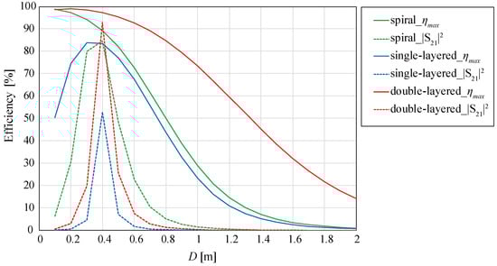
Figure 7.
Transfer distance characteristics of transfer efficiency.
To investigate the improvement mechanism of transmission efficiency, the Q factor is calculated by using the following equation:
where is the resonant frequency. and are the low-frequency and high-frequency at of the peak reflection coefficient, respectively.
The coupling coefficient k is also calculated using the Q factor and kQ product. The kQ product is obtained from the Z parameters [34]:
where is the determinant of the real part of the Z parameter matrix.
The transfer distance D is set to 0.3 m. The calculated Q factor and the coupling coefficient k are shown in Figure 8. It is verified that the Q factor of the folded spiral resonator with a double-layered structure is increased by a factor of four compared to the others. The coupling coefficient k of the folded spiral resonator with a double-layered structure is almost identical to that of the spiral resonator. The coupling coefficient of the folded spiral resonator with a single-layered strucuture is small. This is because the current distribution of the single-layered structure is disturbed because the inner and the outer conductors are laid in an identical plane in turn.
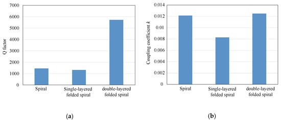
Figure 8.
Q factor and coupling coefficient k: (a) Q factor, (b) Coupling coefficient k.
To investigate undesired far-field emission, the radiation pattern is shown in Figure 9. In this calculation, the Tx and Rx resonators are treated as a transmitting antenna (i.e., the Rx resonator can be considered as a parasitic element of the Tx resonator) to evaluate the far-field radiation as an antenna gain. In the near-field WPT system, far-field radiation becomes an undesired emission, and a lower gain is desired. From this figure, it is confirmed that the far-field radiation of the folded spiral antenna with a double-layered structure is 20 dB less than a conventional spiral resonator.
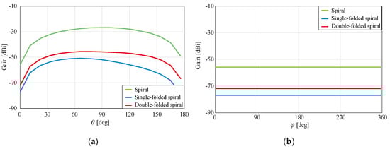
Figure 9.
Radiation pattern: (a) θ direction (z-x plane), (b) φ direction (x-y plane).
5. Comparison with the Conventional Structure
To verify the effectiveness of the folded spiral resonator with a double-layered structure, the transmission efficiency is compared with the conventional structure shown in Figure 10:
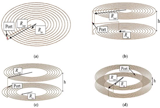
Figure 10.
Single models: (a) short-type single-layered spiral, (b) short-type double-layered spiral, (c) Open-type double-layered self-resonant spiral, and (d) folded spiral resonator with double-layered structure.
- (a)
- Short-type single-layered spiral
A short-type single-layered spiral is shown in Figure 10a. This structure is a conventional inductor. For resonance, a resonant capacitor is used.
- (b)
- Short-type double-layered spiral
A short-type double-layered spiral coupler is shown in Figure 10b. This structure consists of two spirals in a series connection. This structure also acts as a conventional inductor. A resonant capacitor is used.
- (c)
- Open-type double-layered self-resonant spiral
An open-type double-layered spiral coupler is shown in Figure 10c. This structure consists of two open-end spirals. This structure is a self-resonant type, so a resonant capacitor is not necessary.
- (d)
- Folded spiral with a double-layered structure
The proposed structure is shown in Figure 10d.
Consideration Model
The configuration of the numerical simulation is shown in Figure 11. The transfer distance is set to 300 mm. A voltage source with an output impedance of 50 is connected to Port1. A 50 load is connected to Port2. The conductivity of copper assumed.
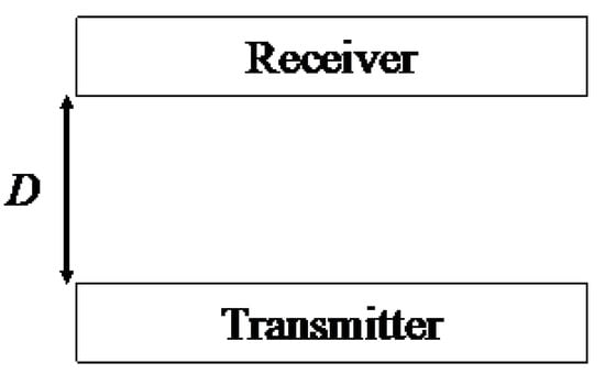
Figure 11.
Consideration model (transmitter (Tx) and receiver (Rx)).
The couplers are optimally designed to compare the characteristics of the couplers with unified external dimensions. The outer diameter is fixed to 150 mm. The height of the single couplers is fixed to 5 mm. The inner diameter and the number of turns are designed to maximize . The optimization frequency is set to 6.78 MHz. The optimized parameters are shown in Table 2.
Table 2.
Designed parameter and characteristics.
The frequency characteristics of the maximum transmission efficiency are shown in Figure 12a. At the resonant frequency of , the double-layered folded spiral achieves its highest efficiency .
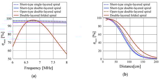
Figure 12.
Characteristics of η_max. (a) Frequency characteristics and (b) transfer distance characteristics.
The transfer distance characteristics of at 6.78 MHz are shown in Figure 12b. The transfer distance of the double-layered folded spiral at which achieves is 1.19 times larger than the open-type double-layered spiral.
To consider the difference between of these couplers, the kQ product, the coupling coefficient , and the Q factor are also shown in Table 2. The Q factor of the double-layered folded spiral resonator presents the highest value. Therefore, it is found that the double-layered folded spiral presents the highest efficiency because of its high Q factor.
6. Conclusions
A folded spiral resonator with a double-layered structure for near-field WPT is proposed. It is verified that the transmission distance over 60% increased by 1.82 and 1.69 times compared to the conventional spiral resonator and the folded spiral resonator with a single-layered structure, respectively. Compared to the conventional spiral resonator, this is caused by the impedance matching effect of the real part of the folded structure. Compared to the folded spiral resonator with a single-layered structure, this is caused by winding the outer conductor and the inner conductor in different planes.
The experimental validation of this is future work.
Author Contributions
The authors have contributed equally to the theoretical development, computational calculation and writing of the paper. All authors have read and agreed to the published version of the manuscript.
Funding
This research was supported by JSPS KAKENHI Grant Number 18K04137.
Conflicts of Interest
The authors declare no conflict of interest.
References
- Hui, S.; Zhong, W.; Lee, C. A Critical Review of Recent Progress in Mid-Range Wireless Power Transfer. IEEE Trans. Power Electron. 2014, 29, 4500–4511. [Google Scholar] [CrossRef]
- Kim, H.-J.; Hirayama, H.; Kim, S.; Han, K.J.; Zhang, R.; Choi, J.-W. Review of Near-Field Wireless Power and Communication for Biomedical Applications. IEEE Access 2017, 5, 21264–21285. [Google Scholar] [CrossRef]
- Imura, T.; Okabe, H.; Hori, Y. Basic Experimental Study on Helical Antennas of Wireless Power Transfer for Electric Vehicles by using Magnetic Resonant Couplings. IEEE Veh. Power 2009, 832–836. [Google Scholar]
- Ahn, S.; Pak, J.; Song, T.; Lee, H.; Byun, J.G.; Kang, D.; Choi, C.S.; Kim, E.; Ryu, J.; Kim, M.; et al. Low Frequency Electromagnetic Field Reduction Techniques for the On-Line Electric Vehicle (OLEV). In Proceedings of the 2010 IEEE International Symposium on Electromagnetic Compatibility, Fort Lauderdale, FL, USA, 25–30 July 2010; pp. 625–630. [Google Scholar] [CrossRef]
- Eghtesadi, M. Inductive Power Transfer to an Electric Vehicle-Analytical Model. In Proceedings of the 40th IEEE Vehicular Technology Conference, Orlando, FL, USA, 6–9 May 1990; pp. 100–104. [Google Scholar] [CrossRef]
- Huang, C.C.; Lin, C.L.; Wu, Y.K. Simultaneous Wireless Power/Data Transfer for Electric Vehicle Charging. IEEE Trans. Ind. Electron. 2017, 64, 682–690. [Google Scholar] [CrossRef]
- Bashirullah, R. Wireless Implants. IEEE Microw. Mag. 2010, 11, S14–S23. [Google Scholar] [CrossRef]
- RamRakhyani, A.K.; Mirabbasi, S.; Chiao, M. Design and Optimization of Resonance-Based Efficient Wireless Power Delivery Systems for Biomedical Implants. IEEE Trans. Biomed. Circ. Syst. 2011, 5, 48–63. [Google Scholar] [CrossRef] [PubMed]
- Ben Amar, A.; Kouki, A.B.; Cao, H. Power Approaches for Implantable Medical Devices. Sens. Basel 2015, 15, 28889–28914. [Google Scholar] [CrossRef] [PubMed]
- Jow, U.M.; Ghovanloo, M. Design and Optimization of Printed Spiral Coils for Efficient Transcutaneous Inductive Power Transmission. IEEE Trans. Biomed. Circ. Syst. 2007, 1, 193–202. [Google Scholar] [CrossRef] [PubMed]
- Kiani, M.; Jow, U.M.; Ghovanloo, M. Design and Optimization of a 3-Coil Inductive Link for Efficient Wireless Power Transmission. IEEE Trans Biomed. Circ. Syst. 2011, 5, 579–591. [Google Scholar] [CrossRef]
- Shinohara, N. History of Research and Development of Beam Wireless Power Transfer4. In Proceedings of the 2018 IEEE Wireless Power Transfer Conference (WPTC), Montreal, QC, Canada, 3–7 June 2018; pp. 1–4. [Google Scholar] [CrossRef]
- Kurs, A.; Karalis, A.; Moffatt, R.; Joannopoulos, J.D.; Fisher, P.; Soljacic, M. Wireless power transfer via strongly coupled magnetic resonances. Science 2007, 317, 83–86. [Google Scholar] [CrossRef]
- Aldhaher, S.; Luk, P.C.K.; Whidborne, J.F. Electronic Tuning of Misaligned Coils in Wireless Power Transfer Systems. IEEE Trans. Power Electron. 2014, 29, 5975–5982. [Google Scholar] [CrossRef]
- Seo, D.W.; Lee, J.H.; Lee, H.S. Optimal Coupling to Achieve Maximum Output Power in a WPT System. IEEE Trans. Power Electron. 2016, 31, 3994–3998. [Google Scholar] [CrossRef]
- Sato, M.; Yamamoto, G.; Gunji, D.; Imura, T.; Fujimoto, H. Development of Wireless In-Wheel Motor Using Magnetic Resonance Coupling. IEEE Trans. Power Electron. 2016, 31, 5270–5278. [Google Scholar] [CrossRef]
- Smeets, J.P.C.; Overboom, T.T.; Jansen, J.W.; Lomonova, E.A. Comparison of Position-Independent Contactless Energy Transfer Systems. IEEE Trans. Power Electron. 2013, 28, 2059–2067. [Google Scholar] [CrossRef]
- Chen, Q.; Ozawa, K.; Yuan, Q.W.; Sawaya, K. Antenna Characterization for Wireless Power-Transmission System Using Near-Field Coupling. IEEE Antennas Propag. Mag. 2012, 54, 108–116. [Google Scholar] [CrossRef]
- Kim, J.; Son, H.C.; Kim, K.H.; Park, Y.J. Efficiency Analysis of Magnetic Resonance Wireless Power Transfer With Intermediate Resonant Coil (vol 10, pg 389, 2011). IEEE Antennas Wirel. Propag. Lett. 2011, 10, 1609. [Google Scholar] [CrossRef]
- Yuan, Q.W.; Chen, Q.; Li, L.; Sawaya, K. Numerical Analysis on Transmission Efficiency of Evanescent Resonant Coupling Wireless Power Transfer System. IEEE Trans. Antennas Propag. 2010, 58, 1751–1758. [Google Scholar] [CrossRef]
- Poon, A.S.Y.; O’Driscoll, S.; Meng, T.H. Optimal Frequency for Wireless Power Transmission Into Dispersive Tissue. IEEE Trans. Antennas Propag. 2010, 58, 1739–1750. [Google Scholar] [CrossRef]
- Haus, H.A.; Huang, W. Coupled-mode theory. Proc. IEEE 1995, 79, 1505–1518. [Google Scholar] [CrossRef]
- Kiani, M.; Ghovanloo, M. The Circuit Theory Behind Coupled-Mode Magnetic Resonance-Based Wireless Power Transmission. Ieee Trans. Circuits Syst. I 2012, 59, 2065–2074. [Google Scholar] [CrossRef]
- Hirayama, H.; Amano, T.; Kikuma, N.; Sakakibara, K. An Investigation on Self-Resonant and Capacitor-Loaded Helical Antennas for Coupled-Resonant Wireless Power Transfer. IEICE TRANS. Commun. 2013, 96, 2431–2439. [Google Scholar] [CrossRef]
- Hirayama, H.; Ozawa, T.; Hiraiwa, Y.; Kikuma, N.; Sakakibara, K. A consideration of electro-magnetic-resonant coupling mode in wireless power transmission. IEICE Electron. Express 2009, 6, 1421–1425. [Google Scholar] [CrossRef]
- Seo, D.W.; Lee, J.H.; Lee, H.S. Study on Two-Coil and Four-Coil Wireless Power Transfer Systems Using Z-Parameter Approach. ETRI J. 2016, 38, 568–578. [Google Scholar] [CrossRef]
- Fotopoulou, K.; Flynn, B.W. Wireless Power Transfer in Loosely Coupled Links: Coil Misalignment Model. IEEE Trans. Magn. 2011, 47, 416–430. [Google Scholar] [CrossRef]
- Kim, J.; Son, H.C.; Park, Y.J. Multi-loop coil supporting uniform mutual inductances for free-positioning WPT. Electron. Lett. 2013, 49, 417–419. [Google Scholar] [CrossRef]
- Kim, H.; Song, C.; Kim, D.H.; Jung, D.H.; Kim, I.M.; Kim, Y.I.; Kim, J.; Ahn, S.; Kim, J. Coil Design and Measurements of Automotive Magnetic Resonant Wireless Charging System for High-Efficiency and Low Magnetic Field Leakage. IEEE Trans. Microw. Theory Tech. 2016, 64, 383–400. [Google Scholar] [CrossRef]
- Hirayama, H.; Amano, T.; Kikuma, N.; Sakakibara, K. A consideration of open- and short-end type helical antennas for magnetic-coupled resonant wireless power transfer. In Proceedings of the 2012 6th European Conference on Antennas and Propagation (EUCAP), Prague, Czech Republic, 26–30 March 2012; pp. 3009–3013. [Google Scholar] [CrossRef]
- Nakamura, K.; Hirayama, H. On a Transmission Efficiency of Tape-wound Spiral Antenna for Coupled Resonant Wireless Power Transfer. In Proceedings of the 2016 International Symposium on Antennas and Propagation (Isap), Okinawa, Japan, 24–28 Octobr 2016; pp. 528–529. [Google Scholar]
- Hirayama, H.; Ando, M.; Sonobe, T. Suppression of Common-mode Radiation Using Folded-spiral Antenna for Wireless Power Transfer. In Proceedings of the 2017 Asia-Pacific International Symposium on Electromagnetic Compatibility (APEMC), Seoul, Korea, 20–23 June 2017; p. 86. [Google Scholar]
- Chou, J.H.; Lin, D.B.; Chen, S.J. Near-Field Coupled Antenna Pair with Transmission Efficiency Enhancement for WPT. In Proceedings of the 2015 Asia-Pacific International Symposium on Electromagnetic Compatibility (Apemc), Taipei, Taiwan, 25–29 May 2015; pp. 275–277. [Google Scholar]
- Ohira, T. Maximum available efficiency formulation based on a black-box model of linear two-port power transfer systems. IEICE Electron. Express 2014, 11. [Google Scholar] [CrossRef]
- Hirayama, H. Unified Coupling and Resonant Model for Near-field Wireless Power Transfer System. In Proceedings of the 2017 IEEE International Conference on Computational Electromagnetics (Iccem), Kumamoto, Japan, 8–10 March 2017; pp. 122–123. [Google Scholar] [CrossRef]
- Hirayama, H.; Komatsu, K.; Yamada, H.; Kikuma, N.; Sakakibara, K. Dielectric Loading Effect of Spiral Tape Antenna for Coupled-resonant Wireless Power Transfer. In Proceedings of the EuCAP 2014, The Hague, The Netherlands, 6–11 April 2014; pp. 2426–2427. [Google Scholar]
- Komatsu, K.; Hirayama, H.; Kikuma, N.; Sakakibara, K. Far-field Radiation and Near-field Leakage of Self-resonant Spiral Antennas for Coupled-resonant Wireless Power Transfer. In Proceedings of the 2013 International Symposium on Electromagnetic Compatibility, Brugge, Belgium, 26 September 2013; pp. 883–886. [Google Scholar]
- Komatsu, K.; Hirayama, H.; Kikuma, N.; Sakakibara, K. A consideration of electric and magnetic coupling coefficient of spiral antenna for wireless power transfer. In Proceedings of the 2012 International Symposium on Antennas and Propagation (ISAP), Nagoya, Japan, 29 October–2 November 2012; pp. 170–173. [Google Scholar]
- Huang, R.H.; Zhang, B. Frequency, Impedance Characteristics and HF Converters of Two-Coil and Four-Coil Wireless Power Transfer. IEEE J. Emerg. Select. Top. Power Electron. 2015, 3, 177–183. [Google Scholar] [CrossRef]
- Moon, S.; Moon, G.W. Wireless Power Transfer System With an Asymmetric Four-Coil Resonator for Electric Vehicle Battery Chargers. IEEE Trans. Power Electron. 2016, 31, 6844–6854. [Google Scholar] [CrossRef]
- Zhang, Y.M.; Zhao, Z.M.; Lu, T. Quantitative Analysis of System Efficiency and Output Power of Four-Coil Resonant Wireless Power Transfer. IEEE J. Emerg. Select. Top. Power Electron. 2015, 3, 184–190. [Google Scholar] [CrossRef]
- Huang, S.D.; Li, Z.Q.; Li, Y.; Yuan, X.F.; Cheng, S.Y. A Comparative Study Between Novel and Conventional Four-Resonator Coil Structures in Wireless Power Transfer. IEEE Trans. Magnet. 2014, 50. [Google Scholar] [CrossRef]
- Guertler, R. Impedance Transformation in Folded Dipoles. Proc. IRE 1950, 38, 1042–1047. [Google Scholar] [CrossRef]
- Miyagoshi, H.; Noguchi, K.; Itoh, K.; Ida, J. High-Impedance Wideband Folded Dipole Antenna for Energy Harvesting Applications. In Proceedings of the 2014 International Symposium on Antennas and Propagation (Isap), Kaohsiung, China, 2–5 December 2014; pp. 601–602. [Google Scholar]
- Furuta, T.; Ito, M.; Nambo, N.; Itoh, K.; Noguchi, K.; Ida, J. The 500MHz band low power rectenna for DTV in the Tokyo area. In Proceedings of the 2016 IEEE Wireless Power Transfer Conference (Wptc), Aveiro, Portugal, 6–7 May 2016. [Google Scholar]
- Ando, M.; Hirayama, H. Impedance Matching using Folded Spiral Antenna for Coupled-resonant Wireless Power Transfer. In Proceedings of the 2016 International Symposium on Antennas and Propagation (Isap), Okinawa, Japan, 24–28 October 2016; pp. 56–57. [Google Scholar]
© 2020 by the authors. Licensee MDPI, Basel, Switzerland. This article is an open access article distributed under the terms and conditions of the Creative Commons Attribution (CC BY) license (http://creativecommons.org/licenses/by/4.0/).