Article

Analysis and Mitigation of Sub-Synchronous Resonance for Doubly Fed Induction Generator under VSG Control

1
College of Electrical Engineering, Zhejiang University, Hangzhou 310027, China
2
State Grid Huaian Power Supply Company, Huaian 223002, China
*
Author to whom correspondence should be addressed.
Energies 2020, 13(7), 1582; https://doi.org/10.3390/en13071582
Submission received: 2 March 2020 / Revised: 19 March 2020 / Accepted: 24 March 2020 / Published: 1 April 2020

Abstract

:
This paper presents the analysis and mitigation of sub-synchronous resonance (SSR) for doubly fed induction generators (DFIG) under virtual synchronous generator (VSG) control, based on impedance methods. VSGs are considered to have grid-supporting ability and good stability in inductance-based weak grids, and are implemented in renewable power generations, including DFIG systems. However, stability analyses of VSGs for DFIG connecting with series capacitor compensation are absent. Therefore, this paper focuses on the analysis and mitigation of SSR for DFIG under VSG control. Impedance modeling of DFIG systems is used to analyze SSR stability. Based on impedance analysis, the influence of VSG control parameters and the configuration of damping factor of reactive power are discussed. Next, a parameter configuration method to mitigate SSR is proposed. Finally, time-domain simulation and fast fourier transform (FFT) results are given to validate the correctness and effectiveness of the impedance model and parameter configuration methods.

1. Introduction

Recently, renewable power generation has developed rapidly. Wind power generation systems (WPGS) based on doubly fed induction generator (DFIG), which has the advantages of relatively low cost and variable speed constant frequency operation, have been widely installed worldwide [1,2]. With the penetration of WPGS in power grids increasing continuously, conventional power sources like synchronous generators (SG) are decreasing; frequency stability and lack of inertia are becoming main concerns in power grids [3]. It is necessary to enhance the ability of WPGS to support power systems like conventional SGs. Based on this consideration, the virtual synchronous generator (VSG) control is proposed [4,5].
VSG is a grid-friendly control strategy which emulates the operating principle of SGs. VSG is first introduced to stabilize the grid frequency by adding virtual rotational inertia to distributed generation systems in [4]. The concepts of “Self-Synchronized Synchronverters” is proposed in [5], in which phase-locked loop can be neglected. The method to stabilize the power system based on VSG control with alternating moment of inertia is introduced in [6]. The comparison of VSG control and droop control are given in [7,8]. According to [8], VSG control inherits the advantages of droop control and provides inertia support for the system. In [9], “virtual synchronized control” for DFIG is presented to increase the inertia support capability and frequency stability of the weak grid. Furthermore, VSG control shows the superior small signal stability better than conventional vector control when a DFIG is connected to a weak grid [10,11].
Wind farms are usually located far away from load center. And wind farms are connected to weak grids through long transmission lines with high impedance. Therefore, series capacitor compensation is usually used to increase power transmission capability among AC lines [12]. However, series capacitors in transmission lines, which connects weak grid with DFIG based wind farms, may cause sub-synchronous resonance (SSR). In recent years, several accidents in DFIG based wind farm caused by SSR have been reported worldwide [13,14].
Currently, the studies of modeling, analyzing and mitigating control strategy for DFIG-based wind farms interconnected with series compensation have been reported in [14,15,16,17,18,19,20]. Based on modal analysis, the impacts of series compensation level, wind speed and current loop gains on SSR are studied in [15,16]. According to [15], the higher compensation level, the lower wind speed and the larger control loop gains, the more possible SSR occurs. As for mitigation strategies of SSR, there are two main methods: (1) auxiliary damping hardware. FACTS devices, such as static var compensator (SVC), thyristor-controlled series capacitor (TCSC) and gated-controlled series capacitors (GCSC), can be used to mitigate SSR [17,18]; (2) damping control strategies. Sub-synchronous resonance damping control is implemented in grid-side converters (GSC) [19] and control performance of different control signals, including rotor speed, capacitor voltage and current magnitude, is analyzed. Intelligent algorithms can be also adopted in suppressing SSR, such as the improved particle swarm optimization algorithm [20].
The works mentioned above focus on the SSR of DFIG under conventional vector control. However, the stability analysis of VSG control in DFIG interconnected with series compensation is absent. Furthermore, VSG control is quite different with vector control, especially in power-synchronization and voltage control loop. Therefore, the stability of DFIG under VSG control in series compensation network should be analyzed in detail.
Impedance modeling is an effective stability analysis method [21,22], which has been used in studying SSR [23,24]. The impedance modeling of VSG control has been implemented in [25], in which VSG control shows the better stability than the vector control in ultraweak inductance-based grid. However, the reactive power and voltage control loops are neglected during VSG modeling, which are very important in VSG control and SSR analysis. Therefore, the impedance model of VSG control for DFIG including voltage control loop should be developed.
The major contributions of this paper can be concluded as: (1) building the detailed impedance model of DFIG under VSG control including DFIG model, swing equation, voltage-reactive power control, frame transformation and rotor voltage calculation; (2) analyzing the influence of VSG control for DFIG on SSR stability and configuring the VSG control parameter based on impedance analysis.
The rest of this paper is organized as follows. In Section 2, VSG control for DFIG is introduced briefly. In Section 3, the impedance modeling of DFIG under VSG control is illustrated. In Section 4, the impedance model is verified and the SSR analysis is also discussed, followed by the influence of VSG control parameters and configuration method are investigated. In Section 5, simulation studies are implemented to verify the correctness and effectiveness of the impedance model and configuration method. Finally, the conclusion is drawn in Section 6.

2. VSG Control for DFIG

In this section, the VSG control for DFIG is introduced. Different with voltage source converters (VSC), the stator of DFIG is connected to the grid directly and outputs the most part of power. Thus, in order to introduce the VSG control for DFIG, the equivalent circuit of DFIG is given in Figure 1. It should be noted that the control target of grid-side converters (GSC) is to keep the constant DC voltage on the DC bus. Therefore, GSC still works in the conventional current vector control [2]. Moreover, GSC has little influence on SSR stability, therefore the analysis of GSC will be neglected in the following [19,23,24].
According to Figure 1, the voltage and flux equations of DFIG in synchronous rotating frame (SRF) can be expressed as:
U s d q = R s I s d q + d ψ s d q / d t + j ω ψ s d q
U r d q = R r I r d q + d ψ r d q / d t + j ω s ψ r d q
ψ s d q = L s I s d q + L m I r d q
ψ r d q = L m I s d q + L r I r d q
ψ m d q = L m I s d q + L m I r d q
where Isdq and Irdq are the stator and rotor current respectively, Usdq and Urdq are the stator and rotor voltage respectively, ψsdq, ψrdq and ψmdq are the stator, rotor and air-gap flux respectively, Lm, Ls and Lr are the mutual, stator and rotor inductance, in which Ls = Lm + L, Lr = Lm + L, L and L are the stator and rotor self-inductance respectively, ω is the SRF angular frequency, ωs is the slip angular frequency, ωs = ωωr, ωr is the rotor angular frequency. All variables are referenced to the stator.
Under steady-state conditions, neglecting differential terms of stator flux ψsdq in (1), the stator voltage model can be represented as:
E DFIG = j ω ψ m d q = U s d q + I s d q ( R s + j ω 1 L s σ )
Similar with the steady stator circuit equation of SG in [26], the term ψmdq in (6) can be defined as the internal voltage EDFIG of DFIG. In this way, the VSG control for DFIG can emulate a conventional SG by controlling the phase and magnitude of ψm.
The phase and magnitude of can be controlled by active power and reactive power, respectively. The phase and frequency reference of ψm can be calculated by the rotor swing equation [5,6,7,8,9,10,11,27]:
ω = 1 J P ( P s * P s + D P ( ω 0 ω ) )   d t + ω 0
θ = ω   d t
where, Ps is the stator active power, P s * is stator active power reference, which can be calculated by the methods of the maximum power point tracking (MPPT) or de-loading control, ω0 is rated angular frequency, JP and DP are the inertia and damping coefficients of active power respectively, θ is the phase reference of EDFIG, which is used in the frame transformation. In this way, the phase-locked-loop (PLL) can be canceled.
The magnitude reference of internal voltage can be calculated by the feedback control of stator voltage and stator reactive power. The reference of reactive power can be set by the grid operators or given by the voltage-drooping, which can be written as:
| E D F I G | * = 1 J Q ( Q s * Q s + D Q ( U 0 | U | ) ) + U 0
where, Qs and Q s * are the stator reactive power and its reference, JQ are DQ are the inertia and damping coefficient of reactive power control loop respectively, U0 is the rated value of grid voltage, |U| is equals to the magnitude of Usdq.
VSG control for DFIG works in the virtual synchronous rotating frame (VSRF), in which d-axis is aligned to EDFIG. And flux feedback control is implemented in control scheme to track the flux reference, which can be expressed as:
E d * = | E D F I G | *       E q * = 0
U r d q * = ( k P + k I ) ( E D F I G * ω ψ m d q )
where, U r d q * is the output of VSG control loop, kP and kI are the proportional and integral coefficients of ωψmdq feedback controller and ωψmdq can be calculated based on (5), respectively.
Based on (7)–(11), the control block diagram of VSG for DFIG is presented in Figure 2. The active and reactive power can be controlled by the phase and magnitude of internal voltage EDFIG, respectively. The inertia and damping characteristics can also be implemented by the rotor swing equation in the VSG control of DFIG.

3. Impedance Modeling of VSG Control for DFIG

In this section, the impedance modeling of VSG control for DFIG is presented. For clarity, bold letters are used in this paper to denote complex space vectors, e.g., X = Xd + jXq; bold letters also denote complex transfer functions or transfer matrix, e.g., X(s) = Xd(s) + jXq(s). Impedance modeling is based on the small signal analysis [21,22], therefore, the state variables with a small-signal perturbation can be written as:
x = X 0 + Δ x
where x is the state variable, X0 is the steady-state value, Δx is the small-signal perturbation, x can denote voltages, currents and other state variables in VSG control of DFIG.

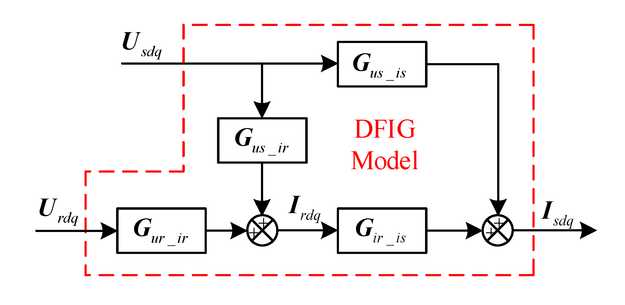
3.1. Modeling of DFIG

Submitting (3) and (4) into (1) and (2) and taking the Laplace transformation of (1) and (2), the small signal model of DFIG can be expressed as:
Δ U s d q = G 1 ( s ) Δ I s d q + G 2 ( s ) Δ I r d q
Δ U r d q = G 3 ( s ) Δ I s d q + G 4 ( s ) Δ I r d q
In the impedance model, the stator voltage and rotor voltage are the inputs of the model; the stator current is the output. Thus, the small-signal model of DFIG can rewritten as:
Δ I s d q = G u s _ i s ( s ) Δ U s d q + G i r _ i s ( s ) Δ I r d q
Δ I r d q = G u s _ i r ( s ) Δ U s d q + G u r _ i r ( s ) Δ U r d q
Figure 3 illustrates the block diagram of transfer matrices of DFIG in the synchronous dq-frame. As can be seen from Figure 3, the stator current depends on the stator voltage and rotor voltage. The transfer functions in (13)–(16) are expressed as:
G 1 ( s ) = [ R s + s L s ω L s ω L s R s + s L s ]
G 2 ( s ) = [ s L m ω L m ω L m s L m ]
G 3 ( s ) = [ s L m ω s L m ω s L m s L m ]
G 4 ( s ) = [ R r + s L r ω s L r ω s L r R r + s L r ]
{ G u s _ i s = G 1 1 G i r _ i s = G 1 1 G 2 G u s _ i r = ( G 3 G 1 1 G 2 + G 4 ) 1 G 3 G 1 1 G u r _ i r = ( G 3 G 1 1 G 2 + G 4 ) 1
where the superscript −1 means the inverse matrix and the subscript us_is means the transfer matrix from stator voltage to stator current, the meanings of other subscripts are similar to this.

3.2. Modeling of Power and Voltage Amplitude

In synchronous dq-frame, the power and voltage amplitude can be calculated as:
{ P s = 1.5 ( u s d i s d + u s q i s q ) Q s = 1.5 ( u s d i s q u s q i s d )
| U | = u s d 2 + u s q 2
By linearizing the (22) and (23), the small-signal-model can be expressed as:
{ [ Δ P s 0 ] = 3 2 [ u s d 0 u s q 0 0 0 ] G i _ P [ Δ i s d Δ i s q ] + 3 2 [ i s d 0 i s q 0 0 0 ] G u _ P [ Δ u s d Δ u s q ] [ Δ Q s 0 ] = 3 2 [ u s q 0 u s d 0 0 0 ] G i _ Q [ Δ i s d Δ i s q ] + 3 2 [ i s q 0 i s d 0 0 0 ] G u _ Q [ Δ u s d Δ u s q ]
[ Δ | U | 0 ] = 1 U 0 [ u s d 0 u s q 0 0 0 ] G U [ Δ u s d Δ u s q ]

3.3. Modeling of VSG Control

The VSG control of DFIG consists two power control loops. The phase and amplitude of internal voltage of DFIG are controlled by active and reactive power loops, respectively. According to (7)–(9), the small signal model of power loops can be written as:
Δ θ = 1 s Δ ω = 1 s 1 J P s + D P Δ P s
Δ | E D F I G | * = 1 J Q s Δ Q s D Q Δ | U |
By submitting (24) and (25) into (26) and (27), the model can be expressed as:
[ Δ θ 0 ] = G P _ θ [ Δ P 0 ] = G P _ θ G i _ P [ Δ i s d Δ i s q ] + G P _ θ G u _ P [ Δ u s d Δ u s q ]
[ Δ E d * 0 ] = G Q _ E [ Δ Q s 0 ] + G U _ E [ Δ | U | 0 ] = G Q _ E G i _ Q [ Δ i s d Δ i s q ] + G Q _ E G u _ Q [ Δ u s d Δ u s q ] + G U _ E G U [ Δ u s d Δ u s q ]
The transfer functions in (28) and (29) are expressed as:
G P _ θ = [ 1 s 1 J P s + D P 0 0 0 ]
G Q _ E = [ 1 J Q s 0 0 0 ]
G U _ E = [ D Q 0 0 0 ]
Based on the (28)–(32), the small signal model of VSG control can be obtained.

3.4. Modeling of Frame Transformation

Since the calculation of rotor voltage are applied in virtual synchronous reference frame (VSRF), the park transformation and inverse park transformation are used in VSG control (green and yellow blocks in Figure 2, respectively). The small-signal perturbation in the angular reference (28) affects the VSG control for DFIG the through the frame transformation. Therefore, the frame transformation should be involved in impedance modeling. It should be noted that the frame transformation does not affect the modeling of DFIG, power calculation and power control loops.
The park transformation (green blocks in Figure 2) of stator and rotor currents can be expressed as:
I d q v = I α β e j θ = ( I d q 0 + Δ I d q s ) e j Δ θ ( I d q 0 + Δ I d q s ) ( 1 j Δ θ ) Δ I d q v = Δ I d q s j I d q 0 Δ θ
where the superscript v means the VSRF and the superscript s means the synchronous dq-frame.
The inverse park transformation (yellow block in Figure 2) of rotor voltage can be expressed as:
U r α β s = U r d q v e j ( θ s + Δ θ ) = ( U r d q 0 + Δ U r d q v ) e j Δ θ s ( U r d q 0 + Δ U r d q v ) ( 1 + j Δ θ ) Δ U r d q s = Δ U r d q v + j U r d q 0 Δ θ

3.5. Modeling of Rotor Voltage

Based on the (5) and (11), the small signal model of rotor voltage can be obtained:
Δ U r d q v = G P I Δ | E D F I G | * + G P I _ i ( Δ I s d q v + Δ I r d q v )
By submitting (33) and (34) into (35), the rotor voltage in synchronous dq-frame can be expressed as:
Δ U r d q s = G u r d q 0 [ Δ θ 0 ] + G P I Δ | E D F I G | * + G P I _ i ( Δ I s d q s + G i s d q 0 [ Δ θ 0 ] ) + G P I _ i ( Δ I r d q s + G i r d q 0 [ Δ θ 0 ] )
The transfer matrixes in (36) are expressed as:
G u r d q 0 = [ u r q 0 0 u r d 0 0 ] G i s d q 0 = [ i s q 0 0 i s d 0 0 ] G i r d q 0 = [ i r q 0 0 i r d 0 0 ]
G P I = [ 1 2 k P s + k I s 0 0 1 2 k P s + k I s ] G P I _ i = ω 0 L m G P I
Based on the (22)–(36), the block diagram of transfer matrixes of VSG control in synchronous dq-frame is presented in Figure 4.
In Figure 4, the currents and stator voltage are the inputs of the VSG and the rotor voltage is the output. Thus, the model can be expressed as:
Δ U r d q s = G u s _ u r Δ U s d q s + G i s _ u r Δ I s d q s + G i r _ u r Δ I r d q s
{ G u s _ u r = ( G u r d q 0 + G P I _ i ( G i s d q 0 + G i r d q 0 ) ) G P _ θ G u _ P             + G P I G Q _ E G u _ Q + G P I G U _ E G U G i s _ u r = ( G u r d q 0 + G P I _ i ( G i s d q 0 + G i r d q 0 ) ) G P _ θ G i _ P             + G P I G Q _ E G i _ Q + G P I _ i G i r _ u r = G P I _ i

3.6. Sequence Impedance of VSG Control for DFIG

The small signal models of DFIG and VSG control have been obtained in Figure 3 and Figure 4, respectively. The detailed model of VSG control for DFIG based on transfer matrices can be presented as Figure 5, in which “△” is omitted for simplicity.
Therefore, the stator current can be expressed as:
U s d q = Z d q I s d q
Z d q = G u r _ i r G i r _ u r + G u r _ i r G i r _ i s G i s _ u r E G u s _ i s + G u s _ i r G i r _ i s + G u s _ u r G u r _ i r G i r _ i s
where the E is the identity matrix. Zdq(s) is the dq-frame impedance model, which is used to reveal the mathematical relations between the models in the dq-domain.
A general dq-frame impedance matrix Zdq(s) is expressed as:
Z d q ( s ) = [ Z d d ( s ) Z d q ( s ) Z q d ( s ) Z q q ( s ) ]
Since the dq-domain impedance model cannot be directly used in the practical situation, the αβ-domain or the sequence-domain model should be obtained. Based on the unifying approach in [22], the sequence-domain model in stationary frame can be expressed as:
Z ± ( s ) = [ Z + d q ( s j ω 1 ) Z d q ( s j ω 1 ) Z d q * ( s j ω 1 ) Z + d q * ( s j ω 1 ) ]
Z + d q ( s ) = Z d d ( s ) + Z q q ( s ) 2 + j Z q d ( s ) Z d q ( s ) 2 Z d q ( s ) = Z d d ( s ) Z q q ( s ) 2 + j Z q d ( s ) + Z d q ( s ) 2
where the subscript ± means the positive-sequence and negative sequence components of impedance and the superscript * means the complex conjugate of the transfer functions.

4. Impedance Validation and SSR Analysis

In this section, the proposed sequence impedance model of VSG control for DFIG will be validated. Then, based on the impedance model, the SSR analysis of VSG control for DFIG interconnected with series compensation is presented. The simulation study is implemented to verify the SSR analysis; several conclusions can be obtained from the impedance analysis. Finally, the influence of VSG parameters on impedance is illustrated in detail. The parameters configuration of VSG is also discussed.

4.1. Impedance Validation

To verify the correctness of the impedance modeling in Section 3, a corresponding simulation model based on Simulink is built. The parameters of DFIG and VSG control for simulation are listed in the Appendix A Table A1; the DFIG is connected to an ideal grid, for the sake of excluding the influence from the grid impedance. The results of impedance model and simulation are given in the case of 0.7 pu rotor speed.
Figure 6 shows the model validation results of impedance in (44) and simulation frequency scanning. As can be seen, the asterisks are all located in the solid lines. It verifies that the impedance model in (44) is accurate in describing the impedance characteristics of VSG control for DFIG.
Since VSG control emulates the operating principle of SG, the impedance of DFIG under VSG is similar with the output impedance of SG [25]. The sequence impedance model of VSG control for DFIG is basically inductive. As can be seen from phase curve, the influence of VSG control can be found mainly around 50 Hz.

4.2. SSR Analysis

To analyze the SSR stability of VSG control for DFIG, a simulation case study of weak grid with series compensation net is introduced first. The simulation study system is derived from IEEE first benchmark model [15,16,23]; its schematic diagram is shown in Figure 7. The DFIG-based wind farm is a 100 MW aggregated equivalent system, which is aggregated from 50 2-MW DFIGs in the Appendix A Table A1. The transformer is 690 V/161 kV. The main parameters of the network system are given in the Appendix A Table A2.
The compensation level can be defined as [12]:
K = X C X L × 100 %
where XL is the inductive reactance of the network including transmission line and transformer, XC is the capacitive reactance in the transmission line.
Based on the impedance theory, instability happens when the impedance ratio curve encircles (−1,0). Therefore, bode plots can be used to analyze resonance stability [23,25]. When the compensation level is 50%, the impedance curve of series compensation network is shown as the black line in Figure 6. As can be seen, there is a magnitude curve intersection at 30 Hz; the phase difference is 187° (more than 180° is unstable), which indicates that there is an SSR instability in the situation; the resonant frequency is 30 Hz.
Figure 8 shows the bode plots of the impedance model developed in [23]. Compared with the proposed model in this paper, only the current control is considered in the impedance model in [23]. VSG control loops and frame transformation are neglected.
As can be seen from Figure 8, when the compensation level is 50%, there is a curve intersection at 27 Hz and the phase difference is 194°. The impedance model in [23] indicates that there is an SSR instability in the situation; the resonant frequency is 27 Hz.
To verify the SSR analysis, a simulation model is built in Matlab/Simulink. The simulation initially operates at 25% compensation level. Then, at t = 1 sec, additional capacitors are switched in, which imitates the transmission line fault and makes the compensation level reach 50%. Figure 9 shows the stator current of DFIG under VSG control; the fast fourier transform (FFT) analysis result of currents is given in Figure 10. As can be seen, SSR occurs at the resonant frequency 30 Hz. Therefore, the following conclusions can be obtained:
  • The DFIG with VSG control also has the SSR problem, when the weak grid reaches a high compensation level.
  • The correctness of proposed impedance model is validated based on the frequency scanning and SSR prediction.
  • Compared with the impedance model only considering current control, the proposed impedance model is more accurate, which indicates that VSG control has an important influence on the SSR.

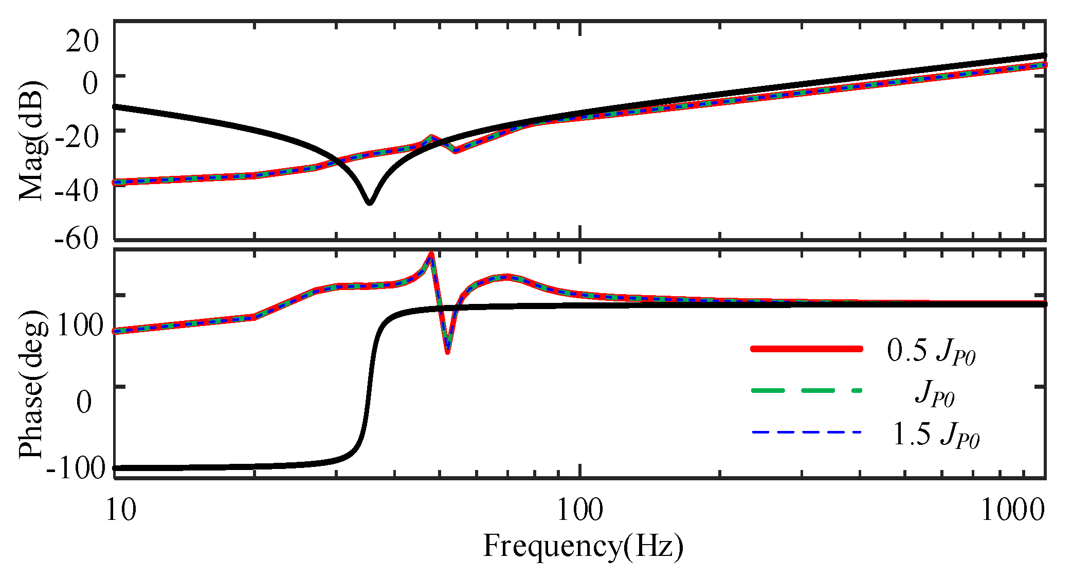
4.3. Influence and Configuration of VSG Control Parameters

The inertia and damping are the key parameters in VSG control. Based on the SSR analysis above, VSG control plays an important role in SSR stability. Therefore, the influence of VSG control parameters is introduced in this section.
Figure 11 shows the bode plots of impedance with different inertia of active power control. The three impedance curves almost overlap each other. As can be seen, the inertia of active power control has little influence on impedance. Thus, inertia of active power cannot be used to mitigate the SSR.
Figure 12 shows the bode plots of impedance with different damping of active power control. As can be seen, the phase decreases when the damping of active power control increases. It means that the phase difference of DFIG and network decreases, which will decrease the possibility of SSR. However, the damping of active power control is associated with primary frequency control [26,27], which configuration is limited according to grid code. Moreover, with the value increasing continuously, the phase variation is small.
Figure 13 shows the bode plots of impedance with different inertia of reactive power control. As can be seen, with the inertia changing, the phase varies without obvious regularity. Therefore, the inertia of reactive power is not suitable for mitigating SSR.
Figure 14 shows the bode plots of impedance with different damping of reactive power DQ. As can be seen, as DQ increases, the phase decreases significantly. It indicates that the damping of reactive power has the ability to mitigate the SSR. When the damping of reactive power increase more than 1.5 DQ0, the phase difference is less than 180 degree, which means that the small SSR disturbance is stable. And it should be noted that phase variation is small when DQ increases continuously. Moreover, with the DQ increasing, the magnitude of impedance intersection decreases, which may slow down the recovery of SSR. With the consideration of phase margin and impedance magnitude, 2 DQ0 is a proper value to mitigates the SSR. The zoom figure is shown in Figure 15.
Table 1 shows the summary of the influence of VSG control parameters. As can be seen, the damping factor of reactive power DQ is suitable for mitigating the sub-synchronous resonance (SSR); the value should be set to 2 DQ0.

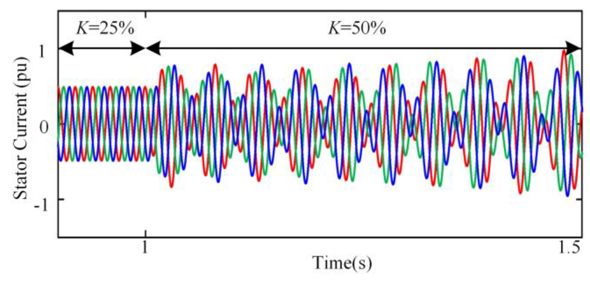
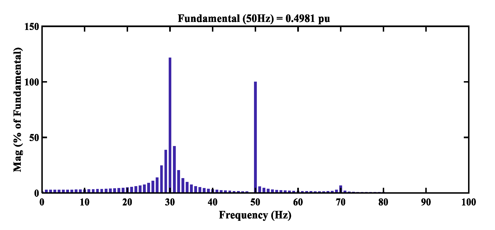
5. Simulation Results

To validate the correctness and effectiveness of the proposed impedance model and parameters configuration method, the simulation results are given in this section. The simulation situation is the same as Figure 9 in Section 4.2. At the 1 sec, the series compensation level increases from 25% to 50%.
Figure 16 shows the results of stator currents with different damping factor DQ. As can be seen, at the 1 s, there is the SSR disturbance caused by series compensation changing. Compared with Figure 9, the SSR disturbance in Figure 16 is mitigated well. When the DQ. increases more than 1.5 DQ0, the phase difference is less than 180°, which means that the SSR disturbance is stable and validates the correctness of the SSR analysis in Section 4.3. According to the FFT analysis, when DQ. increases to 1.5 DQ0, 2 DQ0 and 4 DQ0, the resonant frequency is 30.5 Hz, 31 Hz and 32 Hz, respectively. The FFT results also coincide with the SSR analysis in Figure 15.
Figure 17 shows the simulation results of electromagnetic torque; the enlarged figure of Figure 17 is given in Figure 18. Compared with the conditions of 1.5 DQ0 and 4 DQ0, the attenuation of torque with 2 DQ0 is faster. To illustrate the results more intuitively, the damping time is defined as the length of time that the disturbance in electromagnetic torque damps into 0.05 pu (dashed lines in Figure 17 and Figure 18). The damping time of different parameter’s value is given in the Table 2. When the parameter is 2 DQ0, the damping time is less than 0.5 s. By contrast, the damping time is more than 0.8 s, when the parameter is 1.5 DQ0 and 4 DQ0. The simulation results verify the effectiveness of parameter configuration method.

6. Conclusions

This paper analyzes the SSR stability of DFIG under VSG control based on impedance method. Accurate impedance model of DFIG under VSG control, which considers DFIG model, swing equation, voltage-reactive power control loop, frame transformation and rotor voltage calculation, is developed. It can be found that DFIG with VSG control also has the SSR problem, when the weak grid reaches a high series-compensation level. The simulation results of stator current and FFT result coincide the impedance model analysis well, which indicates that the impedance modeling is an effective way to analyze the SSR in DFIG under VSG control. The influence of VSG control parameters on SSR stability is also analyzed. Based on the impedance analysis, the damping factor of reactive power is suitable for mitigating SSR. With the damping of reactive power increasing, the phase difference between DFIG and network decreases, which means that the damping of reactive power can be designed to mitigate SSR disturbance. Simulation results validate the correctness and effectiveness of the proposed impedance model and parameters configuration method. The robust control to damp SSR disturbance of DFIG under VSG control will be investigated based on the impedance model in the future.

Author Contributions

Conceptualization, Y.J., H.N.; methodology, Y.J., H.N.; software, Y.J., H.N.; validation, Y.J., H.N.; formal analysis, Y.J., H.N.; investigation, Y.J., H.N.; writing—original draft preparation, Y.J.; writing—review and editing, Y.J., H.N.; visualization, Y.J., H.N.; supervision, F.L., H.D.; project administration, F.L., H.D.; funding acquisition, F.L., H.D. All authors have read and agreed to the published version of the manuscript.

Funding

This paper was supported by the National Natural Science Foundation of China under Grant 51977194.

Conflicts of Interest

The authors declare no conflict of interest.

Appendix A

Table A1. Parameters of DFIG and VSG Control.
ParametersValue
Rated power2 MVA
Rated voltage690 V
Rated frequency50 Hz
Stator/Rotor ratio0.34
Mutual inductance (p.u.)3.90
Stator leakage inductance (p.u.)0.171
Rotor leakage inductance (p.u.)0.167
Stator resistance (p.u.)0.0127
Rotor resistance (p.u.)0.0127
DC voltage1200 V
Inertia of active power JP0100
Damping of active power DP0318310(50 × 2 × 10^6/(100π))
Inertia of reactive power JQ0100
Damping of reactive power DQ017750(5 × 2 × 10^6/( 2 / 3 × 690))
Flux control coefficient kP, kI1, 10
Table A2. Parameters of Network System.
ParametersValue
Transformer ratio690 V/161 KV
Rated power100 MVA
Line resistance0.02 pu
Line inductance0.5 pu
Line capacitive reactance at 50% compensation level64.8 Ω

References

  1. Chen, Z.; Guerrero, J.M.; Blaabjerg, F. A review of the state of the art of power electronics for wind turbines. IEEE Trans. Power Electron. 2009, 24, 1859–1875. [Google Scholar] [CrossRef]
  2. Tapia, A.; Tapia, G.; Ostolaza, J.X.; Saenz, J.R. Modeling and control of a wind turbine driven doubly fed induction generator. IEEE Trans. Energy Convers. 2003, 18, 194–204. [Google Scholar] [CrossRef] [Green Version]
  3. Blaabjerg, F.; Ma, K. Future on power electronics for wind turbine systems. IEEE J. Emerg. Sel. Top. Power Electron. 2013, 1, 139–152. [Google Scholar] [CrossRef]
  4. Driesen, J.; Visscher, K. Virtual synchronous generators. In Proceedings of the 2008 IEEE Power and Energy Society General Meeting—Conversion and Delivery of Electrical Energy in the 21st Century, Pittsburgh, PA, USA, 20–24 July 2008; pp. 1–3. [Google Scholar]
  5. Zhong, Q.; Nguyen, P.; Ma, Z.; Sheng, W. Self-synchronized synchronverters: Inverters without a dedicated synchronization unit. IEEE Trans. Power Electron. 2014, 29, 617–630. [Google Scholar] [CrossRef]
  6. Alipoor, J.; Miura, Y.; Ise, T. Power system stabilization using virtual synchronous generator with alternating moment of inertia. IEEE J. Emerg. Sel. Top. Power Electron. 2015, 3, 451–458. [Google Scholar] [CrossRef]
  7. D’Arco, S.; Suul, J.A. Equivalence of virtual synchronous machines and frequency-droops for converter-based MicroGrids. IEEE Trans. Smart Grid 2014, 5, 394–395. [Google Scholar] [CrossRef]
  8. Liu, J.; Miura, Y.; Ise, T. Comparison of dynamic characteristics between virtual synchronous generator and droop control in inverter-based distributed generators. IEEE Trans. Power Electron. 2016, 31, 3600–3611. [Google Scholar] [CrossRef]
  9. Wang, S.; Hu, J.; Yuan, X.; Sun, L. On inertial dynamics of virtual-synchronous-controlled dfig-based wind turbines. IEEE Trans. Energy Convers. 2015, 30, 1691–1702. [Google Scholar] [CrossRef]
  10. Wang, S.; Hu, J.; Yuan, X. Virtual synchronous control for grid-connected dfig-based wind turbines. IEEE J. Emerg. Sel. Top. Power Electron. 2015, 3, 932–944. [Google Scholar] [CrossRef]
  11. Huang, L.; Xin, H.; Zhang, L.; Wang, Z.; Wu, K.; Wang, H. Synchronization and frequency regulation of dfig-based wind turbine generators with synchronized control. IEEE Trans. Energy Convers. 2017, 32, 1251–1262. [Google Scholar] [CrossRef]
  12. Reader’s guide to subsynchronous resonance. IEEE Trans. Power Syst. 1992, 7, 150–157. [CrossRef]
  13. Irwin, G.D.; Jindal, A.K.; Isaacs, A.L. Sub-synchronous control interactions between type 3 wind turbines and series compensated AC transmission systems. In Proceedings of the 2011 IEEE Power and Energy Society General Meeting, San Diego, CA, USA, 24–28 July 2011; pp. 1–6. [Google Scholar]
  14. Wang, L.; Xie, X.; Jiang, Q.; Liu, H.; Li, Y.; Liu, H. Investigation of SSR in Practical DFIG-based wind farms connected to a series-compensated power system. IEEE Trans. Power Syst. 2015, 30, 2772–2779. [Google Scholar] [CrossRef]
  15. Fan, L.; Kavasseri, R.; Miao, Z.L.; Zhu, C. Modeling of DFIG-based wind farms for SSR Analysis. IEEE Trans. Power Deliv. 2010, 25, 2073–2082. [Google Scholar] [CrossRef]
  16. Fan, L.; Zhu, C.; Miao, Z.; Hu, M. Modal analysis of a DFIG-based wind farm interfaced with a series compensated network. IEEE Trans. Energy Convers. 2011, 26, 1010–1020. [Google Scholar] [CrossRef]
  17. Varma, R.K.; Auddy, S.; Semsedini, Y. Mitigation of subsynchronous resonance in a series-compensated wind farm using FACTS controllers. IEEE Trans. Energy Convers. 2008, 23, 1645–1654. [Google Scholar] [CrossRef]
  18. Mohammadpour, H.A.; Santi, E. Modeling and control of gate-controlled series capacitor interfaced with a dfig-based wind farm. IEEE Trans. Ind. Electron. 2015, 62, 1022–1033. [Google Scholar] [CrossRef]
  19. Fan, L.; Miao, Z. Mitigating SSR using DFIG-based wind generation. IEEE Trans. Sustain. Energy 2012, 3, 349–358. [Google Scholar] [CrossRef]
  20. Yao, J.; Wang, X.; Li, J.; Liu, R.; Zhang, H. Sub-synchronous resonance damping control for series-compensated DFIG-based wind farm with improved particle swarm optimization algorithm. IEEE Trans. Energy Convers. 2019, 34, 849–859. [Google Scholar] [CrossRef]
  21. Cespedes, M.; Sun, J. Impedance modeling and analysis of grid-connected voltage-source converters. IEEE Trans. Power Electron. 2014, 29, 1254–1261. [Google Scholar] [CrossRef]
  22. Wang, X.; Harnefors, L.; Blaabjerg, F. Unified impedance model of grid-connected voltage-source converters. IEEE Trans. Power Electron. 2018, 33, 1775–1787. [Google Scholar] [CrossRef] [Green Version]
  23. Miao, Z. Impedance-model-based SSR analysis for type 3 wind generator and series-compensated network. IEEE Trans. Energy Convers. 2012, 27, 984–991. [Google Scholar] [CrossRef]
  24. Liu, H.; Xie, X.; Zhang, C.; Li, Y.; Liu, H.; Hu, Y. Quantitative SSR analysis of series-compensated DFIG-based wind farms using aggregated RLC circuit model. IEEE Trans. Power Syst. 2017, 32, 474–483. [Google Scholar] [CrossRef]
  25. Wu, W.; Chen, Y.; Zhou, L.; Luo, A.; Zhou, X.; He, Z.; Yang, L.; Xie, Z.; Liu, Z.; Zhang, M. Sequence impedance modeling and stability comparative analysis of voltage-controlled vsgs and current-controlled VSGs. IEEE Trans. Ind. Electron. 2019, 66, 6460–6472. [Google Scholar] [CrossRef]
  26. Kundur, P.; Balu, N.J.; Lauby, M.G. Power System Stability and Control; McGraw-Hill: New York, NY, USA, 1994. [Google Scholar]
  27. Nian, H.; Jiao, Y. Improved virtual synchronous generator control of DFIG to ride-through symmetrical voltage fault. IEEE Trans. Energy Convers. 2019. [Google Scholar] [CrossRef]
Figure 1. Equivalent circuit of the doubly fed induction generator (DFIG) model.
Energies 13 01582 g001
Figure 2. Control block diagram of virtual synchronous generator (VSG) for DFIG.
Energies 13 01582 g002
Figure 3. The model of DFIG in synchronous dq-frame.
Energies 13 01582 g003
Figure 4. Block diagram of small signal transfer matrices for VSG control in synchronous dq-frame.
Energies 13 01582 g004
Figure 5. The whole block diagram of transfer matrices of DFIG with VSG control in synchronous dq-frame.
Energies 13 01582 g005
Figure 6. Model validation by frequency scanning, the lines are calculated by the impedance matrix (44), the asterisks are obtained by simulation results. Red and blue lines are positive and negative impedance, respectively. The black line is the impedance of network at 50% compensation level.
Energies 13 01582 g006
Figure 7. Diagram of a DFIG-based wind farm connecting the grid with a series-compensated transmission line.
Energies 13 01582 g007
Figure 8. Bode diagram. Red line is the impedance in [23]. The black line is network impedance.
Energies 13 01582 g008
Figure 9. Waveform of stator currents, at the 50% series-compensation level.
Energies 13 01582 g009
Figure 10. Fast Fourier transform (FFT) analysis of stator currents, at 50% series-compensation level.
Energies 13 01582 g010
Figure 11. Bode diagram of different inertia of active power. Red line: 0.5 JP0; green dash line: JP0; blue dash line: 1.5 JP0.
Energies 13 01582 g011
Figure 12. Bode diagram of different damping of active power. Red line: 0.5 DP0; green line: DP0; blue line: 1.5 DP0.
Energies 13 01582 g012
Figure 13. Bode diagram of different inertia of reactive power. Red line: 0.5 JQ0; green line: JQ0; blue line: 1.5 JQ0.
Energies 13 01582 g013
Figure 14. Bode diagram of different damping of reactive power. Red line: DQ0; green line: 1.5 DQ0; blue line: 2 DQ0; pink line: 4 DQ0.
Energies 13 01582 g014
Figure 15. Zoom Bode diagram of different damping of reactive power.
Energies 13 01582 g015
Figure 16. Waveform of stator currents.
Energies 13 01582 g016
Figure 17. Waveform of electromagnetic torque.
Energies 13 01582 g017
Figure 18. Enlarged waveform of electromagnetic torque.
Energies 13 01582 g018
Table 1. Influence of VSG Parameters Increasing.
Inertia of Active PowerDamping of Active PowerInertia of Reactive PowerDamping of Reactive Power
Has little influence on impedance.Phase decreases.
But limited by the grid code.
Phase varies without obvious regularity.Phase decreases.
×××
Table 2. SSR damping time.
Damping of reactive power1.5 DQ02 DQ04 DQ0
Damping time>0.8 s<0.5 s>0.8 s

