Abstract
Offshore locations present significant amounts of wave energy and free sea space, which could facilitate the deployment of larger numbers of wave energy converters (WECs) in comparison with nearshore regions. The present study aims to find a suitable design for an offshore floating version of CECO, a sloped motion WEC. For this purpose, a new design methodology is proposed in this paper for identifying and assessing possible floating configurations of CECO, which consists of four distinct set-ups obtained by varying the type of main supporting structure and the mooring system. Two options are based on spar designs and the other two on tension leg platform (TLP) designs. Based on outcomes of time-domain numerical calculations, the aforementioned configurations were assessed in terms of annual wave energy conversion and magnitude of mooring loads. Results indicate that a TLP configuration with an innovative mooring solution could increase the annual energy production by 40% with respect to the fixed version of CECO. Besides, the mooring system is found to be a key component, influencing the overall system performance.
1. Introduction
Extracting energy from ocean waves at offshore locations can be considered a profitable venture with enormous potential related to both economic development and responsible growth. Global wave energy is a conspicuous resource, and it presents advantages compared to other natural resources such as solar and wind energy. Compared to these other forms of renewable energy, wave energy can be predicted with lower uncertainty, days in advance, allowing the input of electricity produced to be better managed by the electrical network. In addition, the production of electricity from waves, in contrast to sun or wind, would allow reduced visual impacts, both onshore and offshore, and land occupation. Besides, since wave energy is a concentrated form of solar and wind energy, harvesting technologies would have smaller dimensions for the same rated power. To date, many offshore wave energy converter (WECs) designs have been proposed; nevertheless, no particular concept has reached a commercial-stage of development [1]. The main three obstacles to industrialisation relate to reliability, efficiency, and economic viability. While reliability can be improved by refining the design and implementing existing industry standards [2,3,4], the economic viability can be achieved by choosing the right system design, reducing structural costs, and guarantying higher energy absorption efficiency.
Far from shore, more wave energy per unit of wave crest width is available and less limiting factors related to space for allocating large wave energy farms exist. By further considering the economy of scale, it is reasonable to believe that the first large wave energy farms will be located at a certain distance from the shore, and these will require floating devices. Offshore WECs can be subdivided into two main groups: earth-reacting and self-reacting. For instance, earth-reacting WECs are the Edinburgh Duck [5] and the Ceto point absorber [6]. Earth-reacting WECs, functioning as surging oscillating wave energy converters, are between the most efficient offshore designs, presenting high capture width ratios (CWR) [7], an example of a fixed type can be found in [8,9]. Nevertheless, worthy efficiency can also be obtained with self-reacting devices. Examples are the Wavebob [10] and the Searev [11]. Self-reacting WECs work thanks to the relative motion of multiple floating bodies or the relative motion of internally moving masses (inertial systems).
For both categories of offshore WECs, hundreds of different inventions have been proposed, but no particular concept has yet reached a final stage of development, been massively produced or deployed at industrial scale. Mostly, the absence of industrialisation relies on the lack of an efficient, economically-viable, and universally accepted WEC solution. The majority of the proposed WEC concepts absorb energy from waves, mainly, by means of oscillations of a floater alongside conventional degrees of freedom (DoF), i.e., surge, heave, or pitch. Fixed devices, such as the Wave Star [12], absorb energy from one DoF and have only one mode of motion. In contrast, floating devices may have multiple modes of motions and eventually absorb energy from one or two DoFs, as examples Pelamis [13], Weptos [14], and M4 [15] WECs. Only a few alternative designs, based on oscillation along an inclined axis, have been proposed [16,17]. However, using an inclined degree of freedom may improve overall absorption efficiency [18]. Given this context, the CECO device was conceived. This WEC is based on absorbing wave power from an inclined degree of freedom using the relative motion between two floating lateral mobile modules (LMMs) and a central supporting structure [19].
Earlier studies, supported by results of experimental tests, indicated that the CECO device wave-to-wire power absorption efficiency could be as high as 30% in irregular sea states [20,21]. To date, the CECO concept was developed for a fixed configuration, for which the main supporting structure consists of a pile rigidly installed into the seabed. The concept may also be integrated within offshore wind structures, either fixed or floating types of turbines. Nevertheless, CECO-based technology could also be applied at offshore locations by developing an independent design solution. In this case, the main supporting structure would be a floating unit, moored to the seabed for station-keeping purposes. The present study attempted to find a preliminary design solution for a floating offshore-installed CECO (named OCECO).
Different design solutions regarding a supporting floating structure (SFS) for CECO are feasible. Conventional methods used in naval architecture or offshore engineering are not directly applicable for designing a WEC. However, existing floating structure designs could be adapted for the case of WECs if opportunely modified. The spar, the tension leg platform (TLP), and the semi-submersible systems are the most suitable solutions, as these were designed for stationary use. Moreover, methods for analysing and designing the aforementioned types of conventional floating structure were extensively developed over previous decades [22,23,24,25].
Concerning floating WECs, in contrast to conventional floating structures, the power-take-off (PTO) mechanism, the mooring system, the hull shape, and the mass distribution have to be optimized for both, maximising the power absorbing performance during operational conditions and, as well, for assuring survivability during extreme sea states. For WECs, the power-take-off (PTO) system is an additional component to be included in the design effort. Various PTOs have been proposed for wave energy applications, these, for instance, can be based on hydraulics, air turbines, hydro turbines, direct mechanical drives, and direct electrical drive systems [26]. Depending on the PTO force, a different dynamic response occurs. Floating WECs have additional mooring system requirements compared to conventional floating structures [27]. Since the mooring system affects the system behaviour, the integration of its design within the complete system analysis is imperative for ensuring the identification of the best solutions. For selecting and designing the optimal mooring system, particular attention should be paid to reduce high mooring loads and maximize annual energy production (AEP). On one hand, previous requirements, related to the reliability of securing a floating structure, remain essential, and existing methodologies can support WEC design [28,29]. On the other hand, new requirements related to the objective of maximizing the energy absorption performance have to be considered [30,31,32].
The dynamic behaviour of a WEC due to the action of wave loads determines its power absorption performance. The effects of the PTO and of the mooring system over the dynamic response of a WEC are typically well estimated only when system nonlinearities are taken into account. Thus, it is necessary to apply dynamics-based methods for predicting motions, structural loads and energy production. Significant nonlinear effects can be captured accurately by implementing dynamics-based methods with time-domain analysis [33]. For these reasons, the conventional potential flow approach based on boundary element methods (BEM), such as ANSYS® AQWATM [34], WAMIT® [35], or Nemoh [36] are traditionally used for WEC design. The dynamic-based approach allows estimating the behaviour of WECs in a wide range of operational sea states with a reasonable computational effort [37]. This numerical approach requires validation with experimental data as was the case, for instance, while developing the CECO [20] and for the heaving point absorber treated by Bacelli et al. [38].
In this framework, the main objective of the present work is to propose a preliminary design of a floating offshore version of CECO, named OCECO. At first, the original CECO technology is described (Section 2). Following this is a detailed description of the proposed methodology and of its implementation within the study (Section 3). By applying the mentioned methodology, specific floating arrangements were found feasible (Section 4). These configurations are then compared by evaluating the annual energy production at a reference site and the magnitudes of mooring loads (Section 5). The four alternative designs are then discussed furtherly by considering important additional factors (Section 6). Finally, in Section 7, the outcomes of the study are summarized, and future work recommendations are provided.
2. The CECO Concept
CECO can be categorized as an oscillatory body type of WEC. In contrast to traditional systems, which absorb wave energy from a conventional degree of freedom (DoF) such as heave, surge, or pitch, the CECO device absorbs wave energy from an inclined DoF that is a combination of heave and surge motions. The device consists of a central supporting structure and a set of two lateral mobile modules (LMMs) that are rigidly connected by an inner sliding frame. Under wave loads, the LMMs and the sliding frame are constrained to oscillate along an inclined axis, from side to side of the fixed reference supporting structure (Figure 1). The translation of the LMMs occurs between upper and lower limits, which depend on the length of the sliding frame. When the LMMs reach one of the limits, these are rebounded by an end-stop.
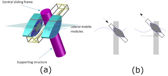
Figure 1.
Scheme of the CECO device (a) and CECO working principle (b).
Various power take-off (PTO) systems and control strategies, to be applied to WECs, have been proposed and studied [39,40,41,42]. Among the different operating principles of PTO systems for WECs, the following stand out: hydraulic, rotatory, and linear generators [10,43]. Due to reliability reasons, at sea, it is better to opt for more plain solutions instead of complex options. For this reason, CECO is equipped with a simple rotatory generator actuated by a rack-pinion system. This PTO mechanism allows converting the kinetic energy of the LMMs motion directly into electricity. Furthermore, the PTO of CECO operates without any additional components, such as springs, providing additional restoring forces. Indeed, hydrostatic forces give the system total restoring condition for its operation.
The CECO design was improved over recent years. Numerous shapes of the floater [19], different sliding angles [44], and PTO damping values were investigated [21], both by numerical and by experimental work. The LMMS geometry was improved; Figure 1 illustrates the CECO device with the new optimized LMMs shape. Earlier studies also indicated that varying the sliding angle might considerably increase power-absorbing performance. For particular ocean climates, an optimum angle of inclination can be selected. At Portuguese offshore locations, considered in previous studies, optimal sliding angles are in the range between 30° and 45° [44]. Depending on the angle of inclination, the LMMs have a different natural period of oscillation. With lower angles, higher natural periods can be obtained. Thanks to the hydrostatic restoring forces, when the optimal sliding angle and the right LMMs’ cross-section geometric shape are selected, a resonant condition can be achieved for a specific sea state (typically the most recurrent and energetic one), allowing maximum power to be absorbed. The inclination angle could be set as a fixed design parameter, as in the case of the present study, but, in theory, it could also be considered variable if a specific control strategy is implemented.
The original CECO concept was first defined for fixed-pile-based installations and to be eventually integrated on horizontal axis offshore wind turbine piles. A fixed supporting structure for the CECO at relatively deep waters (<40 m) would be high-priced due to structural and installations costs. Thus, alternative designs based on a supporting floating structure are investigated in this work.
3. Supporting Floating Structure for CECO
3.1. Design Approach and Methodology
The design of a CECO configuration for offshore applications (OCECO) started with the identification of a suitable supporting floating structure (SFS). For this purpose, different design options related to existing floating wind turbine structures, namely the spar and the tension leg platform (TLP), were considered feasible. The semisubmersible option was not taken into consideration, as this does not appear to be a possible configuration for the WEC system under analysis. In practice, if the SFS of CECO is a semisubmersible arrangement, formed by three or four vertical cylindrical elements, this would cause interference by diffracting incoming waves and intensely reduce the power-absorbing performance of the device.
The CECO concept at relatively deeper offshore locations could be implemented with two different main designs. The first consist of a spar solution and involves the use of catenary mooring lines. In contrast, the second design is based on a tension leg platform (TLP) solution and involves the use of tethers as mooring system. While in the first case the SFS would be a spar buoy, in the second case it would be a TLP. Whereas for the spar solution the device could be categorized as a self-reacting type of WEC, in the case of using a TLP design the device could be categorized as an earth-reacting type of WEC.
In order to identify a feasible design solution for the OCECO device, a series of main aspects have to be considered. The first two aspects relate to identifying, alongside an optimal design for normal operating conditions and a viable design for operational-limit sea states. In addition, further important aspects, that should be diminished, are the structural mass, the structure complexities, the mooring lines length and the installation footprints.
With the purpose of identifying the preliminary spar and TLP designs, the following steps were followed:
- 1.
- Set maximum topside weight, mooring lines length and mooring system weight;
- 2.
- Initial definition of geometry, mass and dimensions of SFS;
- 3.
- Preliminary numerical assessment of the design concept;
- 4.
- Eventually, enlarge geometry features if the assessment in Step 3 is not satisfactory;
- 5.
- Reduce sizes of main supporting floater by minimizing parameters (dimensions and mass) and by evaluating the device under few recurrent sea states;
- 6.
- Numerical assessment of the design by considering operational-limit sea states. At this stage, mooring forces are evaluated. Eventually, if maximum mooring loads are found to be over specific thresholds, the design procedure is repeated from the beginning (Step 1).
Successively, additional steps, for further improving and assessing the identified configurations, were undertaken:
- 7.
- Comparison of power absorption performances with power absorbed by the equivalent fixed CECO device;
- 8.
- Evaluation of the power matrix and calculation of the annual energy production and mooring loads statistics;
- 9.
- Analysis of further factors related to the advantages and drawbacks of each of the examined configurations.
3.2. Numerical Approach
The hydrodynamic behaviour of an offshore CECO device made of two floating structures can be described by:
While Equation (1) represents the lateral mobile modules (LMMs) dynamics, Equation (2) characterizes the dynamics of the supporting floating structure (SFS). In both equations, and are the displacement vectors respectively for the LMM and SFS, m represents the mass and hydrodynamic added mass, the excitation force vectors including both Froude-Krylov and diffraction components up to the second-order, the wave radiation forces due to the moving bodies, the hydrostatic restoring forces, mechanical damping force induced to the LMMs by the PTO system, the forces due the to end-stops, the forces due to the power-take-off system and the mooring reaction forces acting on the SFS.
Equations (1) and (2) characterize all conventional 6 degrees of freedom (DoFs), namely surge, sway, heave, roll, pitch, and yaw (Figure 2). However, for lateral symmetry and mono-directional sea, the DoFs of interest may reduce to surge, heave, and pitch.
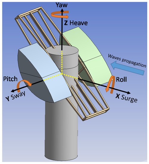
Figure 2.
Reference system and directions of motions.
The hydrostatic restoring forces and moments can be calculated by:
where the first equation is solved merely by integrating the hydrostatic pressure over the wet surface of the body and the second needs to be integrated also by taking into account the position vector , which defines each point on the wet surface of the floating body relative to the centre of gravity.
The PTO mechanism counteracts and dampens the motion of the LMMs by the load , which is in magnitude equal to but of opposite sign. The PTO force () depends on the PTO damping value ( and the relative velocity ) between the floating bodies (LMMs and SFS), as for:
Before integrating Equations (1) and (2) in the time domain, the three-dimensional potential flow theory is applied for obtaining the required hydrodynamic parameters (added mass, radiation damping and diffraction force coefficients). The fluid-structure interaction problem is solved by implementing a boundary element method (BEM) needed to resolve the fluid flow field around the floating bodies, which are represented by diffracting elements. This approach is based on the assumption that water flow is considered irrotational and incompressible and floating bodies have nil forward speed. The flow velocity potential is found by solving the Laplace equation. The hydrodynamic pressure relative to each diffracting element of floating bodies’ wetted surface is evaluated by using Bernoulli’s linearized equation. Thus, the total hydrodynamic forces are obtained by integration of the pressure over the entire wetted surface. The method regards solving in the frequency-domain diffraction and radiation related problems. Initially, the radiation flow field is found by evaluating forced oscillations of the floating bodies (no waves condition). By this operation radiation damping and added mass coefficients are found. Successively, the diffraction problem is solved by considering regular waves and assuming the floating body is fixed. In this way, diffraction force coefficients are obtained. Both mathematical and numerical related methods are quite complex; an extended detailed explanation would be out of the scope of the present paper. Within this study, all hydrodynamic parameters were calculated with the aid of the commercial code based on potential flow theory available in ANSYS AQWA [34].
Successively, through time-domain calculations, the bodies’ dynamics and structural forces were calculated for irregular sea states. Each sea state was evaluated by using excitation forces time series obtained by taking into account random amplitudes generated by employing the JONSWAP sea spectrum (Section 3.5). An irregular sea time series can be defined by implementing the following equations:
where are wave amplitudes, wavenumbers, angular frequencies, are phase values created by defining random irrational numbers between the interval [0; 2]. In Equation (7), is the spectral distribution (defined in Section 9) and is the angular frequency step increment.
All time-domain numerical calculations were performed by means of both ANSYS AQWA and MathWorks® Matlab. The numerical modelling approach implemented in this study is similar to the one used in earlier studies related to the first version of the CECO device. The capability approach implemented to simulate CECO hydrodynamics was comprehensively validated by comparing numerical results with experimental data [20,21,45].
The approach employed is valid for linear waves were relatively small-amplitude displacements occur [10]. In these circumstances, the viscous drag forces acting on the LMMs and the SFS are of little relevance, and thus, for the scope of the study, these are neglected. Nevertheless, viscous effects should be included for increasing results accuracy when extreme sea states and resonance responses have to be investigated in detail.
After time-domain calculations, the theoretical instantaneous absorbed power is estimated, also taking into account the rated power limit of the device, by:
where is the relative velocity between the LMMs and SFS along the inclined axis of oscillation, P the absorbed power and the rated power limit of the device. For mono-directional sea states, can be found using:
where and are the surge and heave velocity components of the LMMs (Index 1) and the SFS (Index 2) bodies. These components correspond to velocities of a point PS on the SFS at the PTO and a point PL at the centre of the LMMs. As for kinematics, and can be obtained from:
where and are the velocity components relative to the centre of gravity (CoG), is the angular velocity of the body, the distance from the point of reference to the CoG and the pitch angle.
3.3. Mooring Systems
Within the study, catenary and tether cables options were employed for spar and TLP configurations respectively. Due to the different types of mooring systems, two modelling methods were used. Both methods relate to reproducing mooring dynamic-restoring forces following discretization of mooring lines with a number of elements subdivided by nodes.
The catenary mooring system was computed using a Lump-Mass model, by which each line is characterized by a series of masses and springs (Figure 3). At contact with the seabed, friction effects are included by using further ideal springs and dampers.
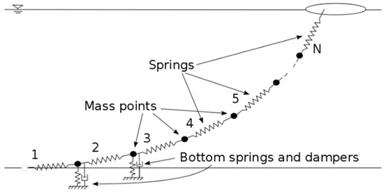
Figure 3.
Lumped-mass model of a catenary mooring line.
For the case of dynamic catenary lines, each cable element can be represented by:
where , and are respectively the tension, the position and the bending moment vectors relative to the first node of an element, the shear force vector, the weight per unit length, the hydrodynamic force vector and the distributed moment per unit length. The equations of catenary elements, together with their related boundary conditions, are then integrated numerically.
On the other hand, tether cables can be modelled as flexible cylindrical tubes, which are discretized in a number of elements that can have different properties. As for a catenary, each element of the tether is divided into a number of nodes (Figure 4).
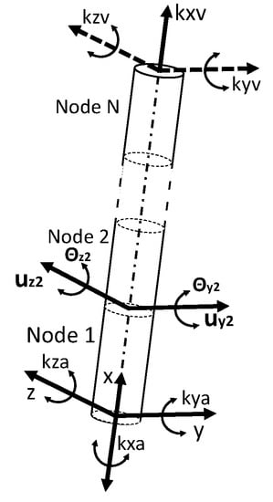
Figure 4.
Discretization of tether elements and conventions used in [34].
Each node of a tether can be expressed as:
where and are the translation and rotations properties of each node; a cubic shape function matrix is then used for characterizing the displacement and rotation of each point along with each node. Tether loads and dynamics are later calculated by defining structural mass and stiffness matrices, by applying external boundaries conditions and by integrating along the whole length of the tether.
Details of the mathematical problem related to the catenary, the tether mooring systems and the numerical method applied can be found in [34].
3.4. End-Stops
The end-stops are modelled as elements having linear spring and linear damping properties. The force exerted by each end-stop is given by:
where is the spring stiffness, the compression offset of the end-stop, the damping constant and the relative velocity of the LMMs. The coefficient can be set by considering the kinetic energy of the LMMs, which can be estimated by:
where and are, respectively, the mass, velocity and the added mass coefficient of the LMMs.
Each time the sliding frame supporting the LMMs reaches its higher and lower limits of operation, it collapses with one of the two end-stops, and a certain amount of kinetic energy is lost, as given by:
where is the initial kinetic energy, the kinetic energy after hitting the end-stop and the energy lost during the contact. is equal to , where is the dissipation coefficient of the end-stop element.
The fixed damping parameter can be then estimated using:
where is the duration of the contact between the sliding frame and the end-stop.
3.5. Power-Take-Off Damping Characterization and Annual Energy Production Assessment
Four OCECO configurations (Conf. 1 to 4) were defined and, along with the fixed CECO configuration (Conf. 0), these were compared between each other, primarily by assessing the annual energy production. For this purpose, the annual wave energy resource of the offshore Portuguese location of São Pedro de Moel (39°49′12″ N, 9°03′36″ W) was taken as reference. This area corresponds to a wave energy testing site with water depths between 30 and 90 m. The wave resource matrix taken into consideration is depicted in Figure 5. The wave climate was characterized by a SWAN model using 10–years long statistics (2005-2014) [45]. The wave energy resource matrix used was obtained by repeating the process employed in a previous study [46]. Forty-five sea states were defined in the time domain based on the standard JONSWAP (Joint North Sea Wave Project) sea spectrum defined by Equation (19) [47], where variables can be obtained with Equations (20) to (22).
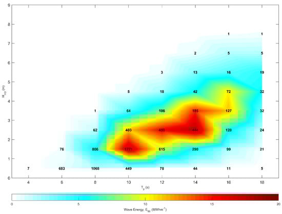
Figure 5.
Wave energy resource matrix for São Pedro de Moel, Portugal (39°49′12″ N, 9°03′36″ W). Numbers represent hours of occurrence relative to each sea state.
In the above equations, is the waves’ angular peak frequency, the angular frequencies considered, the mean wind velocity at 10 m altitude, the fetch length; and , and are specific parameters governing the spectrum distribution. In order to generate each sea state, a fixed peak enhancement factor, , equal to 3.3, was assumed.
The energy extraction estimation is very dependent on the power-take-off damping coefficient () utilized. Thus, allowing a broader analysis not dependent on a single specific value, OCECOs configurations were assessed with a set of different values. Numerical simulations were run for seven damping values (Table 1). In addition, a generator with a rated power of 500 kW was assumed.

Table 1.
Power-take-off (PTO) damping (Cpto) considered values.
To estimate the annual energy production (AEP), for every configuration investigated, only the best values identified for each configuration and for each sea state were applied. The annual energy for each sea state was calculated by multiplying each cell of a specific OCECO configuration power matrix to the relative cell of the wave resource matrix containing the value of hours of the sea state occurrence. The AEP from the WEC is given by:
where, and are respectively, the average power absorbed and the number of hours relative to the i-th sea state. Successively, Equations (24) and (25) can be used for calculating the energy available at sea and the annual capture width ratio (CWR). The total energy available within the characteristic width of the device () is given by:
where is the wave power per unit of wave-crest width available, corresponding to the i-th sea state.
4. OCECO Configurations
Four main options for an offshore CECO (OCECO) unit were identified and analyzed. These configurations were found by applying specific design criteria and following Steps 1 to 6 of the proposed methodology (Section 3.1). Design criteria and details for both, spar platforms and TLPs are described in this section.
4.1. Design Criteria for Spar-OCECO Structures
For the two spar-based SFSs, the mass was set equal to about three times the total mass of the LMMs. The value of the SFS mass was chosen sufficiently large to have appropriately different inertia and natural frequencies with respect to the LMMs. With a lower value of SFS mass, the device would not operate in a stable manner, and relative motion between the SFS and the LMMs would be excessively small. After defining the mass, reasonable values of the radius and the height of the SFS were selected for obtaining the target draft.
In order to limit the pitch oscillation, the centre of mass of the SFS was sufficiently lowered. Similarly, the disk plate included in Configuration 2 was set to be at enough distance below the device for reducing the pitch motion, particularly for the most severe sea states evaluated.
The plate included in Configuration 2 was set to have a diameter equal to the width of the upper part of the device (i.e., 22 m). Larger plates would have damped more the heave motion, however, these were considered to be impractical due to probable high structural costs and existing issues related to possible collisions with the mooring system.
The anchoring points of the catenary mooring system were set to be at a horizontal distance, outwards from the point on the seabed below the centre of the device, for permitting a catenary length of about 3 times the water depth (Figure 6a)
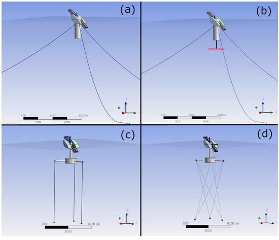
Figure 6.
CECO for offshore applications (OCECO) configurations analyzed: standard spar (a), spar with disk (b), standard tension leg platform (TLP) (c) and TLP with star-shape mooring system (d).
4.2. Design Criteria for TLP-OCECOs
The chosen TLP SFS design of an OCECO device is similar to a TLP design for a floating wind turbine. However, compared to a wind turbine, the CECO system is relatively small. For instance, the height of the device is just about 3 m above the sea level (full scale). Consequently, the pitching moment is significantly smaller, and thus, in the case of CECO, the required buoyancy given by the supporting structure for device functioning can be significantly reduced.
The TLP design applied, seen in Figure 6c and Figure 7b, consists of a main central cylindrical element, a thin high supporting cylinder and three lateral beams where fairleads are located. The buoyancy required for stable operation of the system is given primarily by a main lower cylindrical element. The cylinder shape was chosen for reducing the structural surface and for allowing easy manufacturing. In order to minimize the structural surface, the latter element could have been defined as a sphere, but in that case, it would have been more challenging to construct, deploy and, therefore, consistently more expensive.
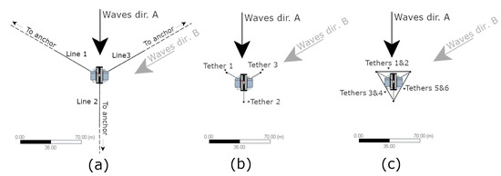
Figure 7.
Top view of mooring systems and configurations analyzed: (a) Conf. 1 (standard spar) and Conf. 2 (spar with disk), (b) Conf. 3 (standard TLP) and (c) Conf. 4 (TLP with star-shape mooring system).
The mooring system for Configuration 3 was defined as a classic set of strait tendons. These standard TLP tethers configuration allows extended surge compliance and can eventually reduce CECO power absorption. Thus, an extra option, i.e., Configuration 4, involved adding three extra tethers and connecting these in a diagonal manner. For this latter case, the mooring system design was modified for increasing the mooring reaction loads aiming at improving the power absorption performances.
4.3. Description of OCECO Configurations Identified
The two configurations based on the spar design share the same SFS (Figure 6a,b). The main difference between them is the presence or not of a disk plate. The disk plate was introduced to the simple spar design (Figure 6b) because initial assessments indicated relatively high heave motion of the SFS, which was negatively impacting the wave energy absorption performances. Both configurations, in this case, are intended to be secured to the seabed by a catenary mooring system formed by three lines, seen in Figure 6a,b and Figure 7a.
The TLP option was assessed with two other configurations, which are illustrated in Figure 6c,d and in Figure 7b,c. Similarly, for the TLP arrangements, the same SFS dimensions, between the two possibilities, were kept unchanged. The only difference between the two cases considered relates to the mooring system applied. For the first case (Conf. 3), a standard TLP with three tendons design is implemented (Figure 6c). Instead, for the second case (Conf. 4), three more lines were added, and connection points were varied to form a star-shape alike mooring system. As illustrated in Figure 6d and Figure 7c, the anchoring points are the same for both Configurations 3 and 4.
4.4. Details of Configurations Studied
The four configurations tested shared the same fixed parameters reported in Table 2 The inclination angle of the LMMs was set to 45°, and the sliding angle of the frame was kept to be 30° in all cases. In addition, also including the fixed CECO configuration assessed, the water depth, the LMMs total mass and generator rated power limit were unchanged.
Table 2.
Fixed parameters used during the study (full scale).
Table 3 reports the main parameters of the SFS assessed. The main difference between the spar and the TLP configurations is the displacement. Clearly, TLPs need extra displacement for allowing enough buoyancy for their stable operation. All dimensions of spar and TLP SFSs are indicated in Figure 8. For Configuration 2a, a plate with a diameter of 22 m was added at a distance of −40 m below the free surface.
Table 3.
Details of the four supporting floating structures (SFS) defined and analyzed (full scale).
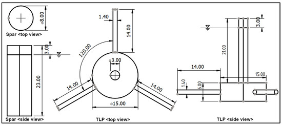
Figure 8.
Dimensions of supporting floating structures (SFSs), in meters.
For the configurations studied, two types of mooring systems were adopted. Table 4 reports the main properties of the mooring lines. While for the first two configurations catenary chains were used, for the second two tethers (tendons).
Table 4.
Main properties of mooring components for the four OCECO configurations investigated in the numerical study.
Hydrodynamic coefficients were calculated for the spar, TLP SFSs, and LMMs geometries by using a boundary element method based on potential flow theory (as described in Section 3.1). This required the representation of the analyzed geometries with quadrilateral flat panels. The spar options were modelled with a total of 350 panels (237 diffracting) and the TLPs with 470 (383 diffracting).
4.5. Other Design Aspects
In order to absorb most of the incoming wave energy, for all configurations considered, it is necessary to introduce a nacelle component to where the LMMs are connected. The nacelle, similarly as for wind turbines, will allow the LMMs to rotate and wave-vane for always facing the primary waves’ direction. The nacelle in the case of OCECO would be shaped as a section of the upper part of the supporting cylinder located in the middle of the LMMs.
The OCECO device will need to deal with the tide level variations. Different designs solutions can be implemented for allowing vertical tide excursion. Concerning the spar design, tide variation would not be a problem, since the floating device is vertically unconstrained and consequently will naturally and easily accommodate tide variations. In contrast, for the case of the TLP SFS, two design approaches can be implemented for allowing tide excursions. The first approach would be to design the connecting sliding frame long enough to allow operation for all the tidal range. Depending on the tide range of a specific location, the latter option may involve very long sliding frames making the solution probably difficult, due to high structural costs. A second solution would be to include a further mechanism that, similarly to the nacelle orientating the LMMs, would lower and uplift the LMMs to operational mean sea water level. An accurate cost-benefit analysis at a later stage of research will be required to address this aspect.
For Configuration 4, it is assumed that two fairlead points are slightly positioned with an offset with respect to the third point so that tendons are not touching between themselves at about the half of their length. For this configuration, tethers have to be eventually reinforced, or somehow sheltered, at their section where possible collisions with other tethers may occur.
5. Results
Following Steps 7–8 of the proposed methodology (Section 4), the defined configurations were assessed aiming at quantifying annual energy production, dynamic response and mooring loads statistics.
Figure 9 and Figure 10 illustrate surge, heave, and pitch time-series of the supporting floating structure (SFS), as well as the instantaneous power absorbed by the device. These results relate to a reference sea state defined by Hs = 1.5 m and Tp = 10 s, which sea state is one of the most frequent ones at the location considered in the study (Figure 5). For this sea state, both surge and heave motions are similar for the spar-based Configurations 1 and 2 (Figure 9). In addition, the pitch motion presents a small amplitude and is characterized by low-frequency oscillations.
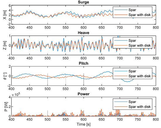
Figure 9.
Time series of surge, heave and instantaneous power output for the spar-based configurations (Conf. 1 & 2). Reference sea state: Hs=1.5 m and Tp=10 s (Cpto = 5 × 10⁴ Ns/m).
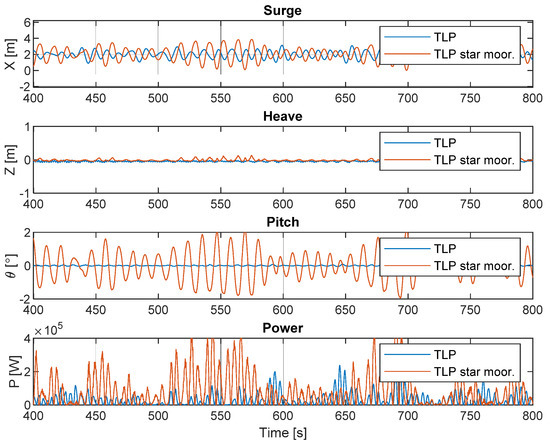
Figure 10.
Time series of surge, heave and power output for the TLP-based configurations (Conf. 3 & 4). Reference sea state: Hs=1.5 m and Tp=10 s (Cpto = 5 × 10⁴ Ns/m).
Configuration 4 presents out-of-phase surge and high-frequency pitch oscillation compared to Configuration 3 (Figure 10). Both TLP configurations present, as expected, small heave motion. For the assessed sea state, the higher power output is obtained from Configuration 4.
For the reference sea state, the effect of a 60° waves’ direction change on the mean power output was examined with the power output from the same configuration, but with different wave direction (Figure 11). The change of waves’ direction does significantly decrease power absorption for Configuration 4 but has only little influence on the other floating configurations. The reason for this is related to the mooring system employed. The dynamic behaviour and performances of Configuration 4 seem to be more dependent on the mooring system (star-shape) with respect to the other configurations.
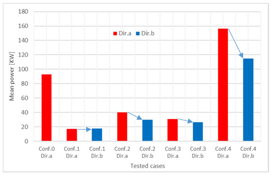
Figure 11.
Mean power absorbed by CECO for the reference sea state characterized by Hs=1.5 m and Tp=10 s. Conf. 0 is the fixed CECO and Conf. 1 to 4 are the floating options.
As for the reference conditions, all other relevant sea states, relative to the wave resource matrix reported in Figure 5, were analyzed within the study. Each sea state was evaluated with time-domain calculations for 20 min of simulation time (full scale). As previously explained, the OCECO configurations were assessed by investigating the power-absorbing performances at different sea states by considering multiple PTO damping values (Cpto). Figure 12 presents the power matrices of respectively, the ideally fixed CECO (Conf. 0) and of Configurations 1 to 4. In these tables, the output power value relative to each sea state represents the average mechanical power absorbed by the device operating with the best Cpto damping value, which is reported alongside in yellow boxes.
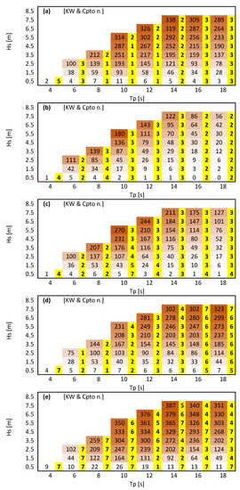
Figure 12.
Power matrices of fixed CECO Conf. 0 (a), and floating Configurations 1 to 4 (b–e). Values are in kW. Numbers in yellow boxes indicate damping values (Table 1).
The annual energy production (AEP), for each of the four OCECO configurations assessed and the fixed CECO unit, was assessed by using the power matrices (Figure 12) and the wave energy resource matrix relative to the case study site (Figure 5), using Equation (23). Results obtained revealed that Configuration 4 is the most efficient one (Figure 13). This configuration can lead to an AEP 40% higher than the AEP of the fixed CECO. Configuration 4 would ideally produce 1040 MWh per year, and its annual CWR would be about 0.49. Besides, the fixed CECO outperforms Configurations 1 to 3. The lowest energy would be obtained with Configuration 1. In addition, it is noted that the potential AEP of Configurations 2 and 3 are similar.
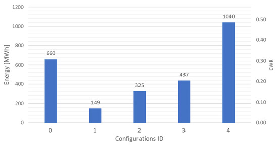
Figure 13.
Annual energy production (AEP) and CWR of the fixed CECO (Conf. 0) and the four configurations assessed (Conf. 1–4).
Results indicate that the reason for higher energy production of Configuration 4 is related to the pitch response. In fact, as can be observed in Figure 10, the pitch motion is greater and is characterized by a relatively higher frequency of oscillations, with respect to all other configurations. This behaviour positively affects power absorption performance.
The mooring line tension relative to an operational-limit sea state, defined by Hs = 7.5 m and Tp = 16 s, was assessed for examining that its maximum value was contained within reasonable thresholds. Figure 14 and Figure 15 present results of the mooring lines tension statistics obtained from the time series relative to each OCECO configuration in terms of box-and-whisker diagrams. In these figures the upper and lower edges of the blue boxes are defined by 75% and 25% percentiles, the red line inside the box indicate the median, further two horizontal marks indicate lower and upper extremes not including outliers which are instead indicated by red crosses. For Configurations 1 to 3, three mooring lines are present, Line 1 is a front line, and Line 2 is the downstream line. For the case of Configuration 4, Lines 1 and 2 refer to the two lines in front and Lines 3 and 4 refer to the lines downstream. As the irregular sea states simulated were mono-directional, and all configurations present particular symmetry, provided results sufficiently describe the performance of all the mooring lines. The conventional waves’ direction and the 60° direction are illustrated in Figure 6.
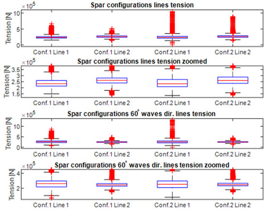
Figure 14.
Mooring lines tension statistics for spar-based configurations, for an irregular sea state representing the operational limit defined with Hs=7.5 m and Tp=16 s.
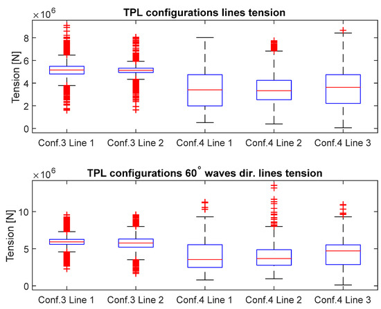
Figure 15.
Mooring lines tension statistics for TLP-based configuration, for an irregular sea state representing the operational limit defined with Hs=7.5 m and Tp=16 s.
Results of mooring tension indicated that a wide range of values might occur for the spar-based configurations. In contrast, TLP configurations present tension values more constrained within 75% and 25% percentiles. All configurations have higher tensions for the 60° direction.
6. Discussion
The present study investigated systematically possible preliminary design configurations for a floating offshore WEC named OCECO, by means of numerical calculations. An effort was made to evaluate viable options minimizing costly and time-consuming initial experimental work related to proofs-of-concept. The experimental work for assessing such moored devices having a realistic PTO system could be reliably done only with large enough scaled models, to be tested in wave tank facilities with suitable water depth. At initial stages of development, when more than one configuration has to be tested, numerical modelling appears as the best option, since offers a good compromise between accuracy and costs, in comparison with model testing.
Apart from the AEP and mooring loads results, there are several additional factors to take into account in comparing the proposed configurations one against the other. Due to this reason, the last step of the proposed methodology, described in Section 3.1 (Step 9), concerns qualitatively assessing the advantages and drawbacks of the defined configurations.
A critical analysis of the different options considered is summarized in Table 5. In this table, ‘+’ symbols are used to compare configurations between them for each listed factor. Configuration 1 is the most unpretentious option; the dimensions of the SFS are sufficient for stable device operation in most recurring sea states. A device based on this configuration could be built at minimal structural costs by eventually using concrete as primary SFS material. However, it appears that, to a certain extent, the SFS moves along with the LMMs, and, thus, the relative motion between the two floating bodies is limited. Therefore, with this configuration, the lowest AEP can be obtained. With Configuration 2, the relative motion between the bodies is increased; in fact, a higher AEP was found compared to Configuration 1. Despite the possible extra energy that can be absorbed with Configuration 2, extra structural costs regarding the disk plate should be prudently taken into account. In terms of performance, Configuration 3 is a slightly better choice compared to Configurations 1 and 2. There are further advantages of Configuration 3 regarding limited total mooring length. Likewise, for Configuration 4, the main advantages of Configuration 3 over Configurations 1 and 2 rely on the limited area required for installation.
Table 5.
Score, main advantages and disadvantages of the OCECO configurations assessed.
Configuration 4 is high performing in terms of AEP and, from this perspective, appears to be the most recommendable option. Nevertheless, the cost of further added extras needed for complying tidal excursion for Configuration 4, as for Configuration 3, should be carefully evaluated. Similarly, for TLP configurations, higher costs exist for installing vertical anchors or suction piles, compared to costs relative to installing drag-embedded anchors, generally used for catenary mooring arrangements.
The present study aimed to find a preliminary design concept by evaluating different possible configurations defined by implementing sensible criteria. For this initial design exercise, geometrical parameters were selected in reasonable ranges, allowing stable operation of the floating device. The next step would be to explore each design parameter more in detail for both the SFS and the LMMs. Due to the configurations’ geometrical complexities, multi-parametric optimizations at an initial stage of development would have been extremely complex and time-consuming. However, by implementing the proposed methodology and discarding some of the initial configurations, accurate parametric optimizations can be done later, more easily, by focusing on one or maybe two promising solutions.
Particular attention should be paid to mooring system design, in terms of properties and materials selection. In this way, the best structural response can be obtained to, eventually, further, increase efficiency and at the same time reduce extreme mooring loads and fatigue.
Mathematical and numerical methods implemented allowed fast computation of several cases and configurations; in order that this was possible, the method implied applying particular assumptions such as linearization of the fluid-structure problem for implementing the potential flow theory. Further numerical work should be planned using classic CFD-based methods to evaluate the dynamics and forces for specific extreme sea states conditions for a single configuration. In this way, all nonlinear effects due to complex fluid-structure interaction, including fluid viscosity, may be analyzed more precisely. Similarly, by following the proposed methodology and having discarded a few configurations, the experimental work needed for validation will be facilitated, as this will focus on only a few specific options.
The present discussion aims at merely comparing preliminarily the considered configurations. In fact, to entirely understand the economic viability of particular wave energy technology, various important other factors should be taken into account, such as the costs for the electrical infrastructure, needed for connecting devices to the electrical network onshore, manufacturing, deployment, operations, and maintenance. A detailed investigation regarding all these other extra costs will allow a decisive estimation of the levelized cost of energy for each of the configuration considered.
7. Conclusions
The scope of the present study was to identify and assess suitable configurations for an offshore-floating version of the CECO wave energy converter. For this purpose, a preliminary design method was defined and applied for obtaining four practical design solutions. Two of the configurations are based on the spar concept and the other two on a TLP arrangement. All configurations were assessed with time-domain numerical calculations. Overall, all four configurations, identified and assessed, showed to operate in a stable manner.
The results indicated that the annual energy production (AEP) is less for Configurations 1 to 3 with respect to the fixed CECO. Nevertheless, Configuration 2 and 3 have comparable performance to the fixed CECO. For Configurations 1 to 3, the motion of the SFS, to a certain extent, negatively affects the power absorbing performance. Conversely, thanks to a more significant relative motion between the SFS and LMM, high power output can be obtained with Configuration 4. In this case, particular SFS pitch resonance is occurring, and this enounces the absorbed power for all sea states. Configuration 4 represents a promising solution for the possible design development of a floating CECO. Despite probable high structural anchoring-related costs, this configuration presents a relatively much higher AEP, minimal footprint, an acceptable total length of mooring lines and comparable mooring tension.
Notwithstanding the preliminary results obtained in the present study, further research is required on the mooring system design, selecting materials and optimal parameters, and control strategies aiming to limit mooring tension during extreme sea states. Lastly, additional work should be conducted on the structural analysis and comprehensive empirical assessments of specific SFSs.
Author Contributions
Conceptualization, G.G., P.R.-S. and V.R.; methodology and numerical study, G.G.; writing—Original draft preparation, G.G.; writing—Review and editing, all authors; supervision, P.R.-S. and F.T.-P.; project management and funding acquisition, F.T.P. and P.R.-S. All authors have read and agreed to the published version of the manuscript.
Funding
This research was financially supported by the Project OPWEC-POCI-01-0145-FEDER-016882 and PTDC/MAR-TEC/6984/2014, funded/co-funded by FEDER through COMPETE 2020-Programa Operacional Competitividade e Internacionalização (POCI) and by Portuguese national funds, through the FCT-Fundação para a Ciência e a Tecnologia, IP.
Acknowledgments
The concept CECO (Patent N. PT 105015) was proposed by Jose Pinho Ribeiro.
Conflicts of Interest
The authors declare no conflict of interest.
References
- Aderinto, T.; Li, H. Ocean wave energy converters: Status and challenges. Energies 2018, 11, 1250. [Google Scholar] [CrossRef]
- DNV. Offshore Service Specification—Certification of Tidal and Wave Energy Converters; DNVGL-SE-0163; Det Norske Veritas AS: Oslo, Norway, 2015. [Google Scholar]
- Group, T.C. Guidelines for Design Basis of Marine Energy Conversion Systems; EMEC: Wakefield, UK, 2009. [Google Scholar]
- Johannesson, P.; Svensson, T.; Santandrea, F.; Ng, C.; Jia, C.; Buck, E.; Shanks, A. Reliability Guidance for Marine Energy Converters; RiaSor: Stromness, Scotland, 2016. [Google Scholar]
- Salter, S.H. The Solo Duck. 1982. Available online: http://www.homepages.ed.ac.uk/v1ewaveg/0-Archive/EWPP%20archive/1982%20EWPP%20The%20Solo%20Duck.pdf (accessed on 10 January 2020).
- Sergiienko, N.Y.; Rafiee, A.; Cazzolato, B.S.; Ding, B.; Arjomandi, M. Feasibility study of the three-tether axisymmetric wave energy converter. Ocean Eng. 2018, 150, 221–233. [Google Scholar] [CrossRef]
- Babarit, A. A database of capture width ratio of wave energy converters. Renew. Energy 2015, 80, 610–628. [Google Scholar] [CrossRef]
- Dias, F.; Renzi, E.; Gallagher, S.; Sarkar, D.; Wei, Y.; Abadie, T.; Cummins, C.; Rafiee, A. Analytical and computational modelling for wave energy systems: The example of oscillating wave surge converters. Acta Mech. Sin. 2017, 33, 1–16. [Google Scholar] [CrossRef] [PubMed]
- Sarkar, D.; Doherty, K.; Dias, F. The modular concept of the oscillating wave surge converter. Renew. Energy 2016, 85, 484–497. [Google Scholar] [CrossRef]
- Falcão, A.F.d.O. Wave energy utilization: A review of the technologies. Renew. Sustain. Energy Rev. 2010. [Google Scholar] [CrossRef]
- Cordonnier, J.; Gorintin, F.; Cagny, A.D.; Clément, A.H.; Babarit, A. SEAREV: Case study of the development of a wave energy converter. Renew. Energy 2015, 80, 40–52. [Google Scholar] [CrossRef]
- Wavestar. Available online: http://wavestarenergy.com/ (accessed on 20 January 2020).
- Yemm, R.; Henderson, R.; Taylor, C. The OPD Pelamis WEC: Current status and onward programme. In Proceedings of the 4th European Wave and Tidal Energy Conference, Alborg, Denmark, 2–5 September 2000. [Google Scholar]
- Pecher, A.; Kofoed, J.P.; Larsen, T. Design specifications for the Hanstholm WEPTOS wave energy converter. Energies 2012, 5, 1001–1017. [Google Scholar] [CrossRef]
- Eatock Taylor, R.; Taylor, P.H.; Stansby, P.K. A coupled hydrodynamic-structural model of the M4 wave energy converter. J. Fluids Struct. 2016, 63, 77–96. [Google Scholar] [CrossRef]
- Salter, S.H.; Lin, C. The sloped IPS wave energy converter. In Proceedings of the 2nd European Wave and Tidal Energy Conference, Lisbon, Portugal, 11–13 September 1995; pp. 337–344. [Google Scholar]
- Payne, G.S.; Pascal, R.; Vaillant, G. On the concept of sloped motion for free-floating wave energy converters. Proc. R. Soc. A Math. Phys. Eng. Sci. 2015. [Google Scholar] [CrossRef]
- Pizer, D. Numerical Modelling of Wave Energy Absorbers; University of Edinburgh: Edinburgh, UK, 1994. [Google Scholar]
- Rosa-Santos, P.; Taveira-Pinto, F.; Rodríguez, C.A.; Ramos, V.; López, M. The CECO wave energy converter: Recent developments. Renew. Energy 2019, 139, 368–384. [Google Scholar] [CrossRef]
- Rodríguez, C.A.; Rosa-Santos, P.; Taveira-Pinto, F. Assessment of the power conversion of wave energy converters based on experimental tests. Energy Convers. Manag. 2018, 173, 692–703. [Google Scholar] [CrossRef]
- Rodríguez, C.A.; Rosa-Santos, P.; Taveira-Pinto, F. Assessment of damping coefficients of power take-off systems of wave energy converters: A hybrid approach. Energy 2019, 169, 1022–1038. [Google Scholar] [CrossRef]
- Agarwal, A.K.; Jain, A.K. Dynamic behavior of offshore spar platforms under regular sea waves. Ocean Eng. 2003. [Google Scholar] [CrossRef]
- Chandrasekaran, S.; Jain, A.K. Triangular configuration tension leg platform behaviour under random sea wave loads. Ocean Eng. 2002, 29, 1895–1928. [Google Scholar] [CrossRef]
- Low, Y.M. Frequency domain analysis of a tension leg platform with statistical linearization of the tendon restoring forces. Mar. Struct. 2009, 22, 480–503. [Google Scholar] [CrossRef]
- Sharma, R.; Kim, T.-W.; Sha, O.P.; Misra, S.C. Issues in offshore platform research—Part 1: Semi-submersibles. Int. J. Nav. Arch. Ocean Eng. 2010, 2, 155–170. [Google Scholar] [CrossRef]
- Pecher, A.; Kofoed, J.P. Handbook of Ocean Wave Energy; Springer: Cham, Switzerland, 2017. [Google Scholar]
- Johanning, L.; Smith, G.H.; Wolfram, J. Mooring design approach for wave energy converters. Proc. Inst. Mech. Eng. Part M J. Eng. Marit. Environ. 2006. [Google Scholar] [CrossRef]
- Cruces Girón, A.R.; Corrêa, F.N.; Vázquez Hernández, A.O.; Jacob, B.P. An integrated methodology for the design of mooring systems and risers. Mar. Struct. 2014. [Google Scholar] [CrossRef]
- Mousavi, M.E.; Gardoni, P. A simplified method for reliability and integrity-based design of engineering systems and its application to offshore mooring systems. Mar. Struct. 2014. [Google Scholar] [CrossRef]
- Johanning, L.; Smith, G.H.; Wolfram, J. Measurements of static and dynamic mooring line damping and their importance for floating WEC devices. Ocean Eng. 2007. [Google Scholar] [CrossRef]
- Harnois, V.; Weller, S.D.; Johanning, L.; Thies, P.R.; Le Boulluec, M.; Le Roux, D.; Soulé, V.; Ohana, J. Numerical model validation for mooring systems: Method and application for wave energy converters. Renew. Energy 2015. [Google Scholar] [CrossRef]
- Xu, S.; Wang, S.; Guedes Soares, C. Review of mooring design for floating wave energy converters. Renew. Sustain. Energy Rev. 2019. [Google Scholar] [CrossRef]
- Penalba, M.; Giorgi, G.; Ringwood, J.V. Mathematical modelling of wave energy converters: A review of nonlinear approaches. Renew. Sustain. Energy Rev. 2017. [Google Scholar] [CrossRef]
- ANSYS. AQWA Reference Manual; ANSYS: Canonsburg, PA, USA, 2017. [Google Scholar]
- WAMIT. The State of the Art in Wave Interaction Analysis. 2019. Available online: https://www.wamit.com/ (accessed on 10 January 2020).
- Babarit, A.; Delhommeau, G. Theoretical and numerical aspects of the open source BEM solver NEMOH. In Proceedings of the 11th European Wave and Tidal Energy Conference, Nantes, France, 6–11 September 2015. [Google Scholar]
- McCabe, A.P. Appraisal of Range of Fluid Modelling Software; Lancaster University Department of Engineering: Lancaster, UK, 2004. [Google Scholar]
- Bacelli, G.; Coe, R.G.; Patterson, D.; Wilson, D. System identification of a heaving point absorber: Design of experiment and device modeling. Energies 2017, 10, 472. [Google Scholar] [CrossRef]
- Wu, J.; Yao, Y.; Zhou, L.; Göteman, M. Real-time latching control strategies for the solo duck wave energy converter in irregular waves. Appl. Energy 2018. [Google Scholar] [CrossRef]
- Wang, L.; Isberg, J.; Tedeschi, E. Review of control strategies for wave energy conversion systems and their validation: The wave-to-wire approach. Renew. Sustain. Energy Rev. 2018. [Google Scholar] [CrossRef]
- Lekube, J.; Garrido, J.A.; Garrido, I.; Otaola, E.; Maseda, J. Flow control in wells turbines for harnessing maximum wave power. Sensors 2018, 18, 535. [Google Scholar] [CrossRef]
- Zoughi, F.M.; Bouallègue, S.; Garrido, A.J.; Garrido, I.; Ayadi, M. Stalling-free control strategies for oscillating-water-column-based wave power generation plants. IEEE Trans. Energy Convers. 2018, 33, 209–222. [Google Scholar] [CrossRef]
- Gaspar, J.F.; Calvário, M.; Kamarlouei, M.; Guedes Soares, C. Power take-off concept for wave energy converters based on oil-hydraulic transformer units. Renew. Energy 2016. [Google Scholar] [CrossRef]
- López, M.; Ramos, V.; Rosa-Santos, P.; Taveira-Pinto, F. Effects of the PTO inclination on the performance of the CECO wave energy converter. Mar. Struct. 2018, 61, 452–466. [Google Scholar] [CrossRef]
- López, M.; Taveira-Pinto, F.; Rosa-Santos, P. Influence of the power take-off characteristics on the performance of CECO wave energy converter. Energy 2017, 120, 686–697. [Google Scholar] [CrossRef]
- Ramos, V.; López, M.; Taveira-Pinto, F.; Rosa-Santos, P. Performance assessment of the CECO wave energy converter: Water depth influence. Renew. Energy 2018. [Google Scholar] [CrossRef]
- Hasselmann, K.; Barnett, T.P.; Bouws, E.; Carlson, H.; Cartwright, D.E.; Enke, K.; Ewing, J.A.; Gienapp, H.; Hasselmann, D.E.; Kruseman, P.; et al. Measurements of the Wind-Wave Growth and Swell Decay during the Joint North Sea Wave Project; Deutsches Hydrographisches Institut: Hamburg, Germany, 1973. [Google Scholar]


© 2020 by the authors. Licensee MDPI, Basel, Switzerland. This article is an open access article distributed under the terms and conditions of the Creative Commons Attribution (CC BY) license (http://creativecommons.org/licenses/by/4.0/).