Abstract
In remote locations such as villages, islands and hilly areas, there is a possibility of frequent power failures, voltage drops or power fluctuations due to grid-side faults. Grid-connected renewable energy systems or micro-grid systems are preferable for such remote locations to meet the local critical load requirements during grid-side failures. In renewable energy systems, solar photovoltaic (PV) power systems are accessible and hybrid PV-battery systems or energy storage systems (ESS) are more capable of providing uninterruptible power to the local critical loads during grid-side faults. This energy storage system also improves the system dynamics during power fluctuations. In present work, a PV-battery hybrid system with DC-side coupling is considered, and a power balancing control (PBC) is proposed to transfer the power to grid/load and the battery. In this system, a solar power conditioning system (PCS) acts as an interface across PV source, battery and the load/central grid. With the proposed PBC technique, the system can operate in following operational modes: (a) PCS can be able to work in grid-connected mode during regular operation; (b) PCS can be able to charge the batteries and (c) PCS can be able to operate in standalone mode during grid side faults and deliver power to the local loads. The proposed controls are explained, and the system response during transient and steady-state conditions is described. With the help of controller-in-loop simulation results, the proposed power balancing controls are validated, for both off-grid and on-grid conditions.
1. Introduction
A low voltage (LV)-rated solar PCS containing a conventional inverter with two-level topologies is preferable for PV systems rated for lower power. For higher power solar power stations, it is better to opt for the system with medium voltage (MV) rating. Multi-level inverters (MLI) are more suitable for MV applications. The cascaded H-bridge (CHB) inverter is a popular MLI configuration which requires isolated DC sources/DC links. Hence CHB configuration is highly suitable for static compensator (STATCOM) and solar applications due to the availability of isolated DC links [1]. CHB inverter needs multiple H-bridge modules, and to control the multiple H-bridge modules, the required input-output channels in the processor are more when compared to other MLI configurations, but in MV high power systems, the CHB inverter enables the independent maximum power point (MPP) controls to attain enhanced efficiency [2]. In high power applications, the number of H-bridge modules to be used in CHB is more which results in better power quality [3,4]. The transformer on the AC side can also be eliminated with this configuration.
Solar PV stations can reduce carbon emissions and provide clean energy but may not be able to supply the load requirements due to sudden changes in weather conditions and when the solar irradiation is weak. The system remains in an idle state during nighttime, which affects the utilization factor of the system drastically. Hence there is much attention to battery energy storage systems along with PV to reduce power disturbances in the system, to improve the stability, for providing continuous power to the load and for improving utilization factor of the system. In such hybrid PV-battery stations, power is transferred from PV array to battery and load during daytime and batteries transfer power to the load during night time. The battery storage system also improves the system dynamics for sudden weather changes [5,6]. Importance of hybrid PV-battery stations and operation strategy is discussed in [7]. A review of energy storage for large-scale PV systems, grid integration issues, stability concerns and the selection of batteries is available in [8]. With the battery storage system in PV applications, the utilization factor of the PCS can also be improved since the system can be made operational for all the time. To keep the grid power non-negative always, an approach called ‘Solar Plus’s which is the combination of energy storage, PV and load controls are presented in [9].
Cost of the battery storage systems is also decreasing over time due to the advancements in the areas of different battery technologies, battery charging and discharging methods. In [10], various battery types such as lithium-ion, lead-acid, aluminium–ion, sodium-sulphur (NaS), flow batteries, etc. suitable for large-scale PV ESS systems are explained and compared. Various discharge strategies are presented for grid-connected hybrid PV-battery applications in [11] and different battery storage technologies suitable for residential applications are also elaborated.
In a conventional grid-connected PV power conditioning system, the anti-islanding feature will be incorporated as a feature of protection. But as mentioned earlier, it may be required to operate the PCS in stand-alone mode also when there are frequent disconnections from the grid. In such scenarios, a power management system at a higher level of control architecture needs to isolate the grid from the critical loads.
Hybrid PV-battery stations can also be operated in standalone mode; hence it is possible to provide power to local critical loads during grid-side faults or during maintenance on the grid side. Such systems help in catering continuous power supply in remote locations which are not connected to the central grid or which are facing problems of regular power supply failures from the grid. Optimal design for a PV + Diesel + Battery storage hybrid system is presented in [12].
From the above, the following research gaps are identified:
- ✓
- In a conventional PV power station, the system remains in an idle state when irradiation is weak; hence the utilization factor (UF) of the system is very small. By incorporating ESS in the solar power system, the overall utilization factor of the system can be improved significantly.
- ✓
- Commercially available PV inverter configurations are based on two-level or three-level inverters with low voltage ratings. These configurations are not suitable for large scale applications, but the medium voltage systems are more suitable for high power applications. The use of conventional two-level inverter for high power applications results in poor power quality, large filter requirement and higher dv/dt across power switches.
- ✓
- A CHB-based PV inverter can nullify the disadvantages of conventional low voltage inverter configurations. An investigation on energy storage systems suitable for CHB inverters is required.
- ✓
- In previous works, controls for PV-battery hybrid system either in grid-connected mode or in standalone modes of operations are discussed but the system controls for operating in both modes are not covered.
Present work mainly focuses on medium voltage CHB-based power condition system to meet the large-scale PV system requirements. For the uninterrupted power supply and to improve the utilization factor of the system, battery energy storage is incorporated in to the PV power system. The following are the contributions of present work to address the research gaps in earlier systems:
- ✓
- A literature review is carried out to investigate various ESS configurations suitable for CHB based inverters. A power conditioning system based on a CHB MLI and battery charger based on a chopper with multiple battery banks is studied thoroughly due to the advantages of chopper-based systems.
- ✓
- A novel power balancing control (PBC) is proposed in this work which enables the system to operate both in standalone mode and in grid-connected mode, unlike earlier works where the controls proposed were for either grid-connected systems or for standalone systems only.
- ✓
- The controls proposed in this work also enable the smooth transition in changing modes of operation.
- ✓
- Controller-In-Loop simulations are carried out with the help of real-time simulator to validate the proposed power balancing controls.
This paper is organized, as explained below: In Section 2, ESS configurations suitable for CHB inverter and advantages of chopper-based ESS are explained. Operation of buck chopper and bi-directional chopper are also elaborated in this section. Section 3 covers the procedure for selection of components such as PV array, batteries, filter components and other accessories. Controls adapted for inverter and battery charger are discussed thoroughly in Section 4 and Section 5, respectively. The setup for the controller-in-loop simulation validation is explained in Section 6 and results are presented in Section 7. Contributions and the conclusions of the present work are presented in Section 8 and Section 9, respectively.
2. Chopper-Based ESS for CHB Inverter
An AC coupled ESS configuration suitable for CHB inverters based on a voltage regulator is presented in [13], but AC-side coupled configurations are not suitable for higher rated energy storage systems as the power quality may get affected due to the multiple interfaces connected on the grid side. DC-coupled systems are more suitable for large-scale energy storage systems and for obtaining better power quality. A dual active bridge (DAB)-based ESS configuration is presented in [14], it is it has been observed that independent power control through PCS and battery charger is possible with this configuration but the control is complex due to a greater number of power modules. Since each DAB needs eight gate pulses, the controller hardware requirements are more. To reduce the cost, controller hardware requirements and the control complexity, it is preferable to select chopper-based systems. In this work, two types of choppers namely buck-chopper and bi-directional choppers, are discussed to operate as a battery charger.
Figure 1 shows the circuit diagram for a buck chopper-based battery charger. In this system, PV voltage shall be more than battery voltage during charging mode. By regulating the duty cycle of IGBT-S1, the charging current is regulated during charging mode. The output filter is used to limit the ripple content of output current and voltage. During the nighttime, PV voltage tends to be less than the battery voltage. Then battery starts giving power to DC link through the third diode ‘D3′. The changeover is instantaneous; hence the system response for transient conditions is also instantaneous. After the transition, the DC voltage is clamped to battery voltage. Since the above charger is operational in charging mode alone, the battery charger and filter inductor need to be selected for the charging current, i.e., usually less than the battery rated current. This reduces the cost of the system. Since the discharging of the battery is through D3, this diode is selected for full current to handle current during discharging mode.
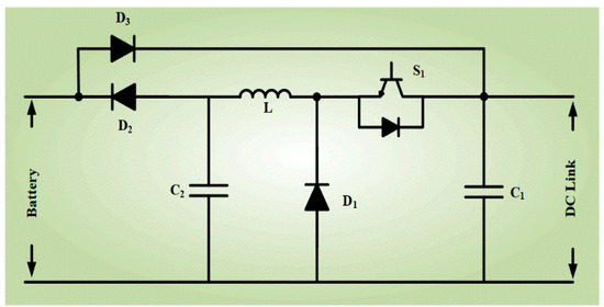
Figure 1.
Battery charger based on a buck-chopper.
The main drawback with this type of charger is that the battery starts discharging only when the irradiation is weak. In grid-connected mode, the battery cannot transfer power to DC link even when the local load demand is higher than the power available at PV array since the PV array is operating at its MPP voltage which is more than the battery voltage. In this case, the power required for the local load needs to be taken from the grid. In standalone mode, the battery needs to provide power along with the PV source for the local critical load requirement due to the absence of the grid. In this case, the PV array cannot be operated at its MPP voltage but operates at battery voltage which reduces the efficiency of PV [15]. So, this charger is more suitable for grid applications. For standalone PV systems, it is required to have control during the discharging mode of operation also which is possible through bi-directional chopper based ESS.
Figure 2 shows a battery charger based on the bidirectional chopper. Unlike the buck chopper, the battery voltage can also be higher than the DC link in this configuration. Battery terminals need to be connected to output terminals of the charger in case the battery voltage is less than DC link. Similarly, battery terminals need to be connected to input terminals of the charger in a case when the battery voltage is more than DC link. This DC-DC converter needs two gate pulses, whereas buck-chopper based system requires only one gate pulse. Cost of this system is less than the DAB based system but slightly more than the buck-chopper based system since the battery charger is selected to the full capacity of the battery. With this charger, battery current in discharging mode can also be controlled hence the PV source can always be operated at MPP voltage in both on and off-grid operations.
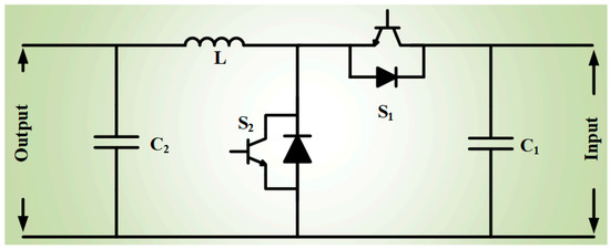
Figure 2.
Bi-directional chopper-based battery charger.
3. Design Calculations for the System
In present work, a high-power PV system with a solar inverter based on a CHB MLI and a bi-directional chopper-based battery charger is studied. To discuss the controls proposed at various operating points and in different modes such as grid-connected and standalone modes, a single-phase system with ratings given in Figure 3 is chosen. In this work, a single-phase system is considered as a case study due to limitations in the controller hardware. However, the system controls can be upgraded to the three-phase system, which is suitable for high power applications.
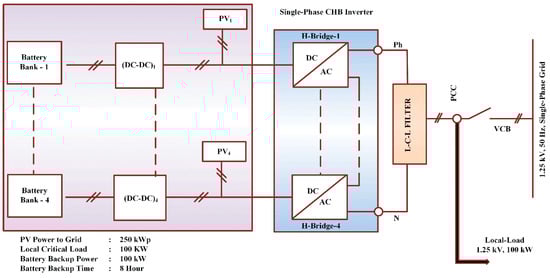
Figure 3.
DC-coupled ESS for CHB-based PCS.
Design calculations for CHB inverters, selection of devices, device loss calculations etc. are discussed in [16,17]. The procedure for the selection of CHB inverter and AC side filter components is shown in Table 1.

Table 1.
Design calculations for CHB Inverter and L-C-L Filter.
To cater to the power needed for local load and power to be transferred to the grid, the required power rating of CHB inverter is 350 kW. In this system, 4 H-bridges are selected hence the levels achieved on the output PWM voltage is nine. The voltage and the power ratings of each H-bridge are 1/4th of CHB ratings and the current rating is equal to the rated inverter output current i.e., 280 amperes. Minimum DC input required for each H-bridge is calculated based on the AC output. In this work, level-shifted PWM is adapted with a carrier frequency of 1 kHz. A filter is used at AC terminals of CHB MLI for obtaining better voltage and current THDs.
In this system, the minimum battery backup power is selected as 100 kW so that the critical load requirement can be met during the standalone mode of operation also. In this work, the battery is selected in such a way that the maximum voltage of the battery is less than the nominal voltage of PV array which is suitable for both the types of chopper based ESS configurations. The lithium-ion battery is selected with a minimum battery voltage depending on the minimum DC input required for each H-Bridge. Procedure for obtaining battery ampere-hour value is also shown in Table 2. After selecting the battery, the PV array is selected by considering that the nominal voltage of the PV array is always higher than the maximum battery voltage. Short circuit current and open-circuit voltage of the PV module is obtained from the datasheet. Minimum MPP voltage of PV array is at the maximum operating temperature range i.e., at 75 °C. Hence ten PV modules in the series are selected to meet the system requirements at 75 °C also. Procedure for selection of PV array is also explained in Table 2.
Table 2.
Selection of battery and PV sources.
Input source to the battery charger is a PV array and the battery is connected to the output terminals. In the case of a buck chopper-based system, the battery charger rating is decided based on charging current which is obtained from the charging time. Ratings of bi-directional chopper-based battery chargers are obtained by a maximum of battery charging and discharging currents. In this work, battery charging and discharging times are selected equal, to maintain equal ratings for Buck-Chopper and bi-directional chopper-based battery chargers. The switching frequency of 5 kHz is selected for the IGBT based battery chargers. An L-C filter is connected to chopper output terminals. Design calculations for filter inductance and capacitance are also shown in Table 3.
Table 3.
Design calculations for the battery charger.
4. Inverter Controls in Different Modes of Operation
Figure 4 shows the building blocks of the CHB inverter which consists of PV switch, IGBT based H-Bridge, bypass module, and transducers. Each building block is fed by independent PV arrays and also connected to independent batteries through chopper-based DC-DC converters. Transducers in the H-bridge module measure PV array voltage and currents for independent MPPT controls. A bypass switch module consisting of antiparallel thyristors and a bypass contactor is used along with H-bridge. Bypass module bypasses the H-bridge during fault so that the system can continue to be operated at reduced power rating.
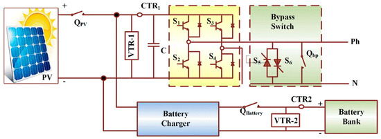
Figure 4.
The basic building block of a CHB-based PCS.
In [18,19,20], regulation of power flow through CHB MLI based PCS are discussed. The control diagram for the power regulation through the inverter is as shown in Figure 5. In grid-connected mode, closed-loop current regulation is implemented and closed-loop voltage regulation is adapted during the standalone mode.
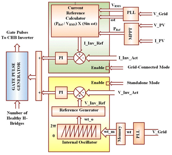
Figure 5.
Control diagram for the CHB inverter in hybrid PV-ESS.
In the grid-connected mode of operation:
- Closed-loop voltage regulators are disabled and the closed-loop current regulators are enabled.
- Through a phase-locked loop (PLL), the phase angle of grid voltage ‘ωt’ is obtained.
- PV Current (I_PV) and PV voltage (V_PV) are monitored for MPP tracking to obtain power reference (PRef) for the inverter.
- Reference inverter current (I_Inv_Ref) is obtained from ‘PRef’, grid voltage, and ‘ωt’,
- By comparing actual and reference inverter currents, current regulators provide a modulating signal.
- Based on the number of healthy H-bridges, carrier waves are generated in the gate pulse generator module
- By comparing carrier and modulating signal, gate signals for CHB MLI are obtained.
In standalone mode, closed-loop voltage control is adapted to provide the rated voltage to the load. For smooth changeover in the mode of operation, it is required to match the phase angle of inverter voltage with the earlier grid voltage. Following activities are carried out in the inverter controls when the system is in standalone mode:
- The grid voltage is monitored and the phase angle ‘ωt’ of grid voltage is obtained through PLL.
- At the moment of occurrence of grid fault, the latest value of angle ‘ωt_m’ of grid voltage is stored and the internal oscillator is enabled.
- The internal oscillator generates a phase angle ‘ωt_o’ which starts from the value of stored phase angle ωt_m.
- On receiving the phase angle input, reference generator gives inverter reference voltage signal to the closed-loop voltage controller.
- By comparing actual and reference inverter voltages, the voltage regulators provide a modulating signal.
- Based on the number of healthy H-bridges, carrier waves are generated in the gate pulse generator module
- By comparing carrier and modulating signal, gate signals for CHB MLI are obtained.
5. Battery Charger Controls in Different Modes of Operation
With a bi-directional chopper-based battery charger, regulation of battery current in charging and discharging modes is possible which allows the PV array to operate at its MPP in all operating conditions. In grid-connected mode, the power available at PV array is used for the charging of the battery and the balance power is transferred to the grid/load as long as irradiance is available. In standalone mode, the power available at PV array power is transferred to the grid/load and the balance power if any is used for charging the battery as long as irradiance is available. In both these modes, if the battery is fully charged or if the power demand on the grid side is more, then the battery can also feed the additional power demand. In this work, battery voltage less than PV voltage is selected, hence the converter acts like a buck-chopper during charging mode and acts like a boost-chopper during discharging mode. Battery charging is always through current control whereas discharging of the battery can be carried out either through the current controller or uncontrolled. Figure 6 shows the control diagram of the bi-directional charger.
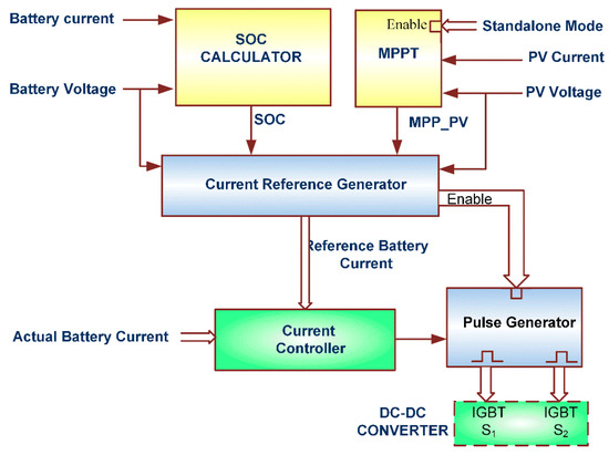
Figure 6.
Control diagram for the bi-directional chopper in PV-ESS.
In grid-connected mode:
- When PV voltage is more than the minimum nominal voltage of PV array, battery charging/discharging current reference is obtained based on battery SOC.
- Convention of battery current is taken as positive during charging mode and negative during discharging mode.
- During charging mode, the current controller compares the actual battery current with reference battery current and generates gate pulse so that the chopper operates as a Buck-Chopper.
- When the reference battery current is negative and the PV voltage is more than the minimum nominal voltage of PV array, then the battery discharging current is controlled through the current controller.
- When the reference battery current is negative, and if the PV voltage is less than the minimum nominal voltage of the PV array, then the pulse generator is disabled. No gate pulse is given to IGBTs and the battery discharges through the inductor (L) and the diode across IGBT-S1. In this mode, the current through the battery charger varies based on the reference inverter power.
In the standalone mode of operation:
- If PV voltage is more than the minimum nominal voltage of PV array, battery charging current reference is obtained based on battery SOC and represented as Ibatt_SOC.
- Another battery current reference is generated through MPPT controls and represented as Ibatt_MPP.
- The minimum value in Ibatt_SOC and Ibatt_MPP is selected as a current reference for the charger.
- While charging the battery, MPPT controls are carried out in the battery charger and adjust the battery reference current to maintain the MPP of the PV array.
- Current reference may also become negative to supply power from the battery when the irradiance on PV array is poor. In this case, also, PV array operates at its MPP voltage.
- When the irradiance becomes zero, then the PV voltage becomes less than the minimum nominal voltage of the PV array and the pulse generator module is disabled. Then battery discharges through inductor L and the diode across IGBT-S1. Based on the load on the AC side, battery current varies.
In this work, a bi-directional chopper-based battery charger is considered for ease of understanding and due to limitations in the controller hardware. For high power applications interleaved buck-boost converters presented in [21] may be adapted with minor modifications in the control logic.
6. Validation of Control Algorithm for Chopper Based ESS Configurations
To validate the system, controller-in-loop simulation validation is adapted. With the controller-in-loop simulations, the control software can be tested prior to the site trials and can be tested at various operating points which are difficult to test with a real plant [22]. The following activities are carried out as part of controller-in-loop simulation validation:
- ✓
- The power circuit also is known as the plant which consists of a grid, input breaker, local load, CHB inverter, PV array, batteries, and battery chargers are simulated as shown in Figure 7 with the help of real-time simulator library
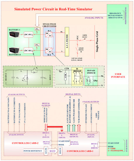 Figure 7. Block diagram of the controller-in-loop simulation setup.
 - ✓
- The simulated model is compiled and loaded in the high-speed processors of the real-time simulator
- ✓
- Input-output channels of the real-time simulator are interfaced with the processor cards and other user interfaces. The real-time simulator enables the simulated plant to operate as a real plant
- ✓
- The user interface consists of pushbuttons to provide start/stop commands and for mode selection. Potentiometers on the user interface are used for varying irradiance value on PV arrays
- ✓
- Due to the limitations in the analogue inputs in the used processor, two processor cards of the same type are used in this work
- ✓
- Control algorithm in processor cards is programmed through MatLab-embedded coder
- ✓
- In controller card-1, the controls for inverter are programmed. It receives start command and mode selection from the user and receives module faulty signals from the plant as digital inputs. Analogue inputs such as grid voltage, inverter voltage, and currents are received from the simulated plant
- ✓
- From the simulated plant, controller-2 receives analogue inputs such as battery current, battery voltage, PV current, and PV. Based on the mode of operation, MPPT is carried out. Battery charger controls are programmed in this controller card
- ✓
- When the start command is given from the user interface, the controllers process the proposed control algorithm to control battery chargers and the CHB inverter
- ✓
- When the system is in grid-connected mode, based on MPPT of PV arrays, the reference power signal is communicated to controller card-1 through a serial communication interface (SCI). Transmission of data is by RS232 protocol
Controller-in-loop simulation setup is shown in Figure 8, Table 4 lists the particulars of the real-time simulator hardware.
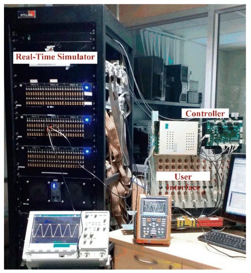
Figure 8.
Controller-in-loop simulation setup.
Table 4.
Hardware details of real-time simulator setup.
7. Results and Discussion
In grid-connected mode, the advantage with the bi-directional chopper-based system is the possibility of discharging even when the PV array is active. The response of the inverter current is observed by operating the battery in charging mode and discharging modes intermittently. Irradiance is continuously maintained at 1000 watt per square meter hence the PV array current is constant. The battery reference current is varied from +50 Ampere to −50 Ampere and vice versa with an equal interval time of 1 s. When the battery current is negative, additional current is flowing through the inverter as shown in Figure 9. The dynamic response of the system in this condition is also found to be satisfactory.
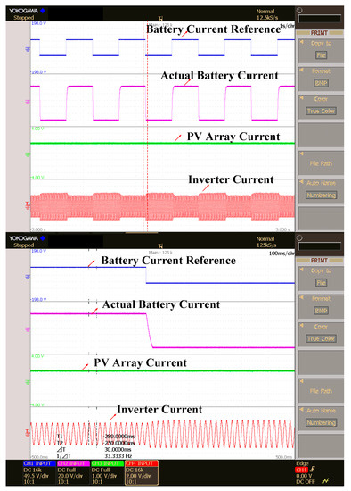
Figure 9.
Change in the battery, PV array and actual inverter currents with a change in reference battery current at constant irradiance of 1000 watt per square meter in a bi-directional chopper-based ESS in grid-connected mode.
Irradiance on the PV arrays is varied from zero watts per square meter to 1000 watt per square meter in steps of 200 watts per square meter and the currents of inverter output, battery and PV array are observed.
As discussed earlier, when the irradiance is zero, the battery current is negative as it is in discharging mode and the inverter power is equal to the rated battery power and PV current is zero as displayed in Figure 10. MPP tracking is carried out in inverter controls hence the inverter current and PV currents are varied in proportion to the irradiance inputs whereas the battery current is almost constant.
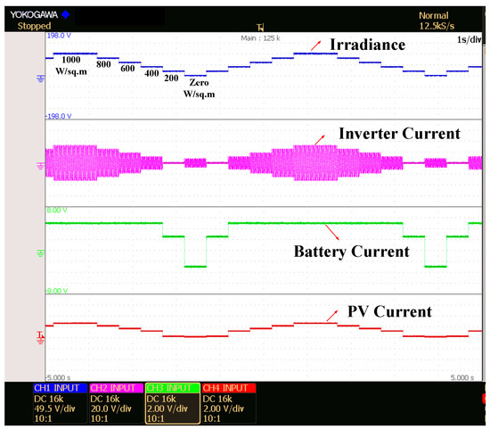
Figure 10.
Inverter, battery and PV currents with varying irradiance value in grid-connected mode.
Irradiance on the PV arrays is varied from 350 watts/sq.m to 1000 watt per square meter in steps as shown in Figure 11 and inverter current is observed. When the grid side is healthy, the current required for charging the battery is provided by PV array and the remaining power is supplied to the grid/load. So, the current through inverter decreases with the reduction in irradiance. PV power is less than the power required for the battery charging when irradiance is 350 watts/sq.m; hence the inverter current is zero. As the irradiance value increases, the power transferred to the grid also increases and shows good dynamic during a sudden change in irradiance input.
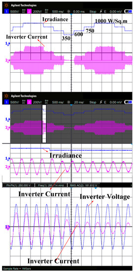
Figure 11.
Change in inverter current with varying irradiance value in grid-connected Mode.
A fault on the H-Bridge module is created to verify system performance. The system continues to operate with reduced power as shown in Figure 12. The proposed algorithm enables the fault-tolerant operation instantaneously and the obtained results are in line with the simulation results presented in [1].
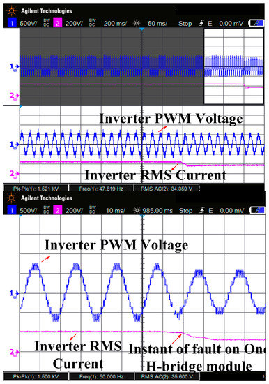
Figure 12.
Inverter PWM voltage and RMS current during a fault in one H-bridge module
Mode of operation is changed from grid-connected to the standalone operation and the transients in the inverter AC voltage i.e., the input voltage to the load are observed. Smooth transition in the inverter voltage is observed during mode transfer as shown in Figure 13. The operation mode is changed from grid-connected to an off-grid mode for a bi-directional chopper-based system. Operation of the system for a fixed load is studied by varying irradiance value from zero to 1000 watt per square meter in steps of 200 Watts/sq.m. Since the load is fixed, inverter current is constant for all the values of irradiance inputs. MPP tracking is carried out in battery charger controls; hence the battery current varies with the irradiance value. At the instant when the PV power is not sufficient to meet the load demand then discharge current of the battery is regulated through current control. In this mode, DC link voltage has maintained the value of the MPP voltage of PV array. As shown in Figure 14, when irradiance value is zero, PV array voltage tends to zero hence the DC link is clamped to the battery voltage level. From the presented results it is observed that the dynamic response of the battery charger system is good as the settling time is in the range of 50 milliseconds, whereas the settling time is in the range of 200 milliseconds in the battery charger systems based on voltage regulator and dual active bridge configurations proposed in [13,14], respectively.
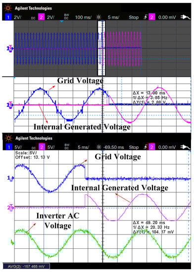
Figure 13.
Grid voltage, internal oscillator voltage and inverter output voltage during a changeover in the mode of operation.
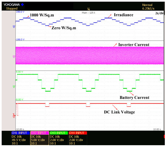
Figure 14.
Change in battery current, inverter current and DC link voltages with a change in irradiance in standalone mode operation.
It is observed that the dynamic response of the solar PV inverter for sudden changes in irradiance input is found satisfactory as the settling time of inverter current is in the range of 50 milliseconds whereas the settling time is in the range of 300 milliseconds in PV inverters with improved perturb and observe method presented in [23].
8. Contributions and Future Scope
In this work, various energy storage system configurations suitable for cascaded H-bridge-based PV inverters are discussed. Design calculations for the chopper-based ESS for PV applications are presented in detail. Controls for the bi-directional chopper-based energy storage systems are studied and a control algorithm is developed and validated through real-time simulations. As future work, the proposed control algorithm can be validated on prototype models of the chopper-based systems or the AC/DC buck-boost converters proposed in [24]. The controls can be extended further for interleaved buck-boost converters to improve the power rating further. In this work, the operation of these systems is explained considering equal irradiances on each PV arrays and the state of charge of each battery bank is also considered equal. System operation for unequal irradiances can be studied as future work in line with the controls proposed in [25]. In present work, a single-phase system is considered; the controls can be extended to the three-phase system in future work. An additional feature of reactive power compensation can also be planned. The present system provides the solution for AC micro-grids for rural areas with frequent disruptions in grid supply. From earlier studies, it found that DC micro-grids are more feasible as PV sources, wind power generator and other renewable sources provide DC current and DC micro-grids are more stable compared to an AC micro-grid [26]. Feasibility of the energy storage system and its controls can be studied for DC grid systems proposed in [27].
9. Conclusions
In this paper, a chopper-based ESS suitable for CHB-based PCS is presented. With the proposed system, the power to the grid/load can be supplied without any interruption. Cost, control complexity and controller hardware requirements for the chopper-based system are less compared to other configurations such as voltage regulator-based ESS and DAB-based ESS configurations. Buck-chopper based ESS configuration identified to be more suitable for grid-connected system and the bi-directional chopper based ESS configuration is suitable for standalone operation as well. The controls proposed for the bi-directional chopper-based ESS is analyzed with the help of controller-in-loop simulations by using a real-time simulator. Good dynamic response of the system for sudden changes in irradiance is observed from the presented results. Smooth transition in the system controls is also achieved during mode change over.
Author Contributions
All authors were involved to articulate the research work for its final depiction as the full research paper. “Conceptualization, U.S, S.V, S.P.; Methodology, U.S., S.P., D.A.; Software, S.V.; Validation, S.P, F.B. and J.B.H.-N.; Formal Analysis, U.S.; Investigation, S.V.; Resources, J.H.N and F.B.; Data Curation, S.P., D.A.; Writing-Original Draft Preparation, U.S., S.P., S.V., D.A.; Writing-Review & Editing, F.B., and J.B.H.-N.; Project Administration, F.B., S.P., J.B.H.-N.; Funding Acquisition, S.P.” All authors have read and agreed to the published version of the manuscript.
Funding
This research received no external funding.
Acknowledgments
The authors like to express sincere gratitude to Renewable Energy lab, Prince Sultan University, Saudi Arabia for making this research work for execution and technical implementation in real-time, and Center for Bioenergy and Green Engineering/Center of Reliable Power Electronics (CORPE), Aalborg University, Esbjerg/Aalborg, Denmark.
Conflicts of Interest
The authors declare no conflict of interest.
References
- Sridhar, V.; Umashankar, S. A comprehensive review on CHB MLI based PV inverter and feasibility study of CHB MLI based PV-STATCOM. Renew. Sustain. Energy Rev. 2017, 78, 138–156. [Google Scholar] [CrossRef]
- Yu, Y.; Konstantinou, G.; Hredzak, B.; Agelidis, V.G. Operation of Cascaded H-Bridge Multilevel Converters for Large-Scale Photovoltaic Power Plants under Bridge Failures. IEEE Trans. Ind. Electron. 2015, 62, 7228–7236. [Google Scholar] [CrossRef]
- Dragonas, F.A.; Neretti, G.; Sanjeevikumar, P.; Grandi, G. High-Voltage High-Frequency Arbitrary Waveform Multilevel Generator for DBD Plasma Actuators. IEEE Trans. Ind. Appl. 2015, 51, 3334–3342. [Google Scholar] [CrossRef]
- Sridhar, V.; Umashankar, S.; Sanjeevikumar, P.; Ramachandaramurthy, V.K.; Mihet-Popa, L.; Fedák, V. Control Architecture for Cascaded H-Bridge Inverters in Large-Scale PV Systems. Energy Procedia 2018, 145, 549–557. [Google Scholar] [CrossRef]
- Chen, L.; Chen, H.; Li, Y.; Li, G.; Yang, J.; Liu, X.; Xu, Y.; Ren, L.; Tang, Y. SMES-Battery Energy Storage System for the Stabilization of a Photovoltaic-Based Microgrid. IEEE Trans. Appl. Supercond. 2018, 28, 1–7. [Google Scholar] [CrossRef]
- Rallabandi, V.; Akeyo, O.M.; Jewell, N.; Ionel, D.M. Incorporating Battery Energy Storage Systems Into Multi-MW Grid Connected PV Systems. IEEE Trans. Ind. Appl. 2018, 55, 638–647. [Google Scholar] [CrossRef]
- Yang, Y.; Ye, Q.; Tung, L.J.; Greenleaf, M.; Li, H. Integrated Size and Energy Management Design of Battery Storage to Enhance Grid Integration of Large-Scale PV Power Plants. IEEE Trans. Ind. Electron. 2018, 65, 394–402. [Google Scholar] [CrossRef]
- Lai, C.S.; Jia, Y.; Lai, L.L.; Xu, Z.; McCulloch, M.D.; Wong, K.P. A comprehensive review on large-scale photovoltaic system with applications of electrical energy storage. Renew. Sustain. Energy Rev. 2017, 78, 439–451. [Google Scholar] [CrossRef]
- O’Shaughnessy, E.; Cutler, D.; Ardani, K.; Margolis, R. Solar plus: Optimization of distributed solar PV through battery storage and dispatchable load in residential buildings. Appl. Energy 2018, 213, 11–21. [Google Scholar] [CrossRef]
- Zhang, C.; Wei, Y.-L.; Cao, P.-F.; Lin, M.-C. Energy storage system: Current studies on batteries and power condition system. Renew. Sustain. Energy Rev. 2018, 82, 3091–3106. [Google Scholar] [CrossRef]
- Olaszi, B.D.; Ladanyi, J. Comparison of different discharge strategies of grid-connected residential PV systems with energy storage in perspective of optimal battery energy storage system sizing. Renew. Sustain. Energy Rev. 2017, 75, 710–718. [Google Scholar] [CrossRef]
- Rodríguez-Gallegos, C.D.; Gandhi, O.; Yang, D.; Alvarez-Alvarado, M.S.; Zhang, W.; Reindl, T.; Panda, S.K. A siting and sizing optimization approach for PV–battery–diesel hybrid systems. IEEE Trans. Ind. Appl. 2017, 54, 2637–2645. [Google Scholar] [CrossRef]
- Vavilapalli, S.; Subramaniam, U.; Padmanaban, S.; Ramachandaramurthy, V.K. Design and Real-Time Simulation of an AC Voltage Regulator Based Battery Charger for Large-Scale PV-Grid Energy Storage Systems. IEEE Access 2017, 5, 25158–25170. [Google Scholar] [CrossRef]
- Vavilapalli, S.; Padmanaban, S.; Subramaniam, U.; Mihet-Popa, L. Power Balancing Control for Grid Energy Storage System in Photovoltaic Applications—Real Time Digital Simulation Implementation. Energies 2017, 10, 928. [Google Scholar] [CrossRef]
- Vavilapalli, S.; Umashankar, S.; Sanjeevikumar, P.; Fedák, V.; Mihet-Popa, L.; Ramachandaramurthy, V.K. A Buck-Chopper Based Energy Storage System for the Cascaded H-Bridge Inverters in PV Applications. Energy Procedia 2018, 145, 534–541. [Google Scholar] [CrossRef]
- Sastry, J.; Bakas, P.; Kim, H.; Wang, L.; Marinopoulos, A. Evaluation of cascaded H-bridge inverter for utility-scale photovoltaic systems. Renew. Energy 2014, 69, 208–218. [Google Scholar] [CrossRef]
- Wang, Z.; Fan, S.; Zheng, Y.; Cheng, M. Design and Analysis of a CHB Converter Based PV-Battery Hybrid System for Better Electromagnetic Compatibility. IEEE Trans. Magn. 2012, 48, 4530–4533. [Google Scholar] [CrossRef]
- Kumar, N.; Saha, T.K.; Dey, J.; Barman, J.C. Modelling, control, and performance study of cascaded inverter based grid connected PV system. In Proceedings of the IREC2015 the Sixth International Renewable Energy Congress, Sousse, Tunisia, 24–26 March 2015; pp. 1–6. [Google Scholar]
- Xiao, B.; Hang, L.; Mei, J.; Riley, C.; Tolbert, L.M.; Ozpineci, B. Modular Cascaded H-Bridge Multilevel PV Inverter With Distributed MPPT for Grid-Connected Applications. IEEE Trans. Ind. Appl. 2014, 51, 1722–1731. [Google Scholar] [CrossRef]
- Iman-Eini, H.; Bacha, S.; Frey, D. Improved control algorithm for grid-connected cascaded H-bridge photovoltaic inverters under asymmetric operating conditions. IET Power Electron. 2017, 11, 407–415. [Google Scholar] [CrossRef]
- Samavatian, V.; Radan, A. A novel low-ripple interleaved buck–boost converter with high efficiency and low oscillation for fuel-cell applications. Int. J. Electr. Power Energy Syst. 2014, 63, 446–454. [Google Scholar] [CrossRef]
- Vavilapalli, S.; Subramaniam, U.; Padmanaban, S.; Blaabjerg, F. Design and Controller-In-Loop Simulations of a Low Cost Two-Stage PV-Simulator. Energies 2018, 11, 2774. [Google Scholar] [CrossRef]
- Kamran, M.; Mudassar, M.; Fazal, M.R.; Asghar, M.U.; Bilal, M.; Asghar, R. Implementation of improved Perturb & Observe MPPT technique with confined search space for standalone photovoltaic system. J. King Saud Univ. Eng. Sci. 2018, 30. [Google Scholar] [CrossRef]
- Li, X.; Wu, W.; Wang, H.; Gao, N.; Chung, H.S.-H.; Blaabjerg, F. A New Buck-Boost AC/DC Converter with Two-Terminal Output Voltage for DC Nano-Grid. Energies 2019, 12, 3808. [Google Scholar] [CrossRef]
- Vavilapalli, S.; Umashankar, S.; Sanjeevikumar, P.; Ramachandaramurthy, V.K.; Mihet-Popa, L.; Fedák, V. Three-stage control architecture for cascaded H-Bridge inverters in large-scale PV systems—Real time simulation validation. Appl. Energy 2018, 229, 1111–1127. [Google Scholar] [CrossRef]
- Marcon, P.; Szabo, Z.; Vesely, I.; Zezulka, F.; Sajdl, O.; Roubal, Z.; Dohnal, P. A Real Model of a Micro-Grid to Improve Network Stability. Appl. Sci. 2017, 7, 757. [Google Scholar] [CrossRef]
- Arunkumar, G.; Elangovan, D.; Sanjeevikumar, P.; Nielsen, J.B.H.; Leonowicz, Z.; Joseph, P.K. DC Grid for Domestic Electrification. Energies 2019, 12, 2157. [Google Scholar] [CrossRef]


© 2020 by the authors. Licensee MDPI, Basel, Switzerland. This article is an open access article distributed under the terms and conditions of the Creative Commons Attribution (CC BY) license (http://creativecommons.org/licenses/by/4.0/).