1. Introduction
Refrigeration systems are used in many areas, including domestic cooling systems, vehicles cooling systems, food storage cabinets, and hydrogen gas liquefaction. One of the most important issues that should be considered in the design of refrigeration systems is the ability to adapt to the environment. In recent years, extensive research has been performed on the use of various types of natural refrigerants such as ammonia (R717) and carbon dioxide (R744) in compressed air systems; however, these refrigerants have some drawbacks. Not only is there a shortage of components in small scale ammonia systems, but ammonia also has a pungent smell, and is both flammable and toxic. Carbon dioxide contributes significantly to global warming and also it is not compatible with all refrigeration system lubricants [
1]. Despite the widespread use of these natural systems, issues such as the possibility of flammability and toxicity are serious barriers to the use of compressed air systems in different parts of industry.
Among the common refrigeration systems, compression refrigeration systems, which use chlorofluorocarbon refrigerators, are regarded as the most harmful to the environment; that is, they are responsible for global warming and ozone layer depletion.
In this regard, a magnetic refrigeration system can be developed as a replacement with similar efficiency, yet without any negative effects on the ozone layer, as compared with various compression refrigeration systems. Unlike liquid refrigerants, solid refrigerants do not enter the atmosphere and, therefore, have no direct environmental impact. The magnetic refrigeration system is based on the magnetocaloric effect. This property appears in the presence of a magnetic field. In magnetocaloric materials, the magnetic moments of the atoms are aligned with the external magnetic field. By applying the magnetic field, the magnetocaloric material (MCM) temperature increases and the entropy decreases as a result of the decreased disorder in the system. When the magnetic field is removed, the magnetic moment of the atoms returns to a random orientation, with the result that the entropy is increased and the MCM temperature is reduced.
The magnetocaloric effect is expressed in two forms: Either a temperature change if the magnetic field changes adiabatically or an entropy change if the magnetic field changes at a constant temperature. The maximum magnetocaloric effect occurs near the Curie point of the magnetocaloric material. The Curie point of MCM is the temperature at which the material changes from the ferromagnetic state to the paramagnetic state.
The efficiency of the magnetic refrigeration system is about 30–60% of the Carnot cycle, while the compression efficiency is between 5% and 10% of the Carnot cycle [
2].
Numazawa et al. [
3] compared two different regenerator geometries. The results showed the optimal geometries and dimensions of the regenerator at different frequencies. It was also shown that the flat parallel plates model can obtain a lower entropy and achieve a higher cooling capacity.
Aprea et al. [
4] compared two different geometries of the regenerator—a porous medium and a flat plate. The results showed that for the flat plate regenerator, the coefficient of performance (COP) of the active magnetic regenerator (AMR) cycle is higher than that of the vapor compression plant only in the high-mass-flow-rate range.
Lozano et al. [
5] published the experimental results of a laboratory-made magnetic refrigeration system. The material and prototype used were Gd and a rotary, respectively. The performance of the system was studied with fluid flow rate up to 600 L/h and the frequency up to 10 Hz.
In a study by Monfared et al. [
6], the environmental effects of two magnetic cooling systems and a compression refrigeration system were compared. The effect of the electricity consumption for different operational alternatives, as an effective parameter in the life cycle assessment, was also investigated.
A study of regenerator geometries was performed by Lei et al. [
7]. The results showed that the parallel plate and microchannel matrices had the highest theoretical efficiency, while the packed screen and packed sphere beds were possibly more appropriate from a practical point of view.
Another study examined the economic costs of the magnetic refrigeration system. In this study, the initial cost of the magnetocaloric and the magnetic materials and utility costs were taken into account in determining the final cost of the system. For a period of 15 years, the final cost of the device was estimated to be around
$150 to
$400, depending on the price of the magnetocaloric material and the magnetism. For a refrigeration system with a magnetic field of 1 T, frequency of around 4.5 Hz, and a COP of two, for generating a cooling power of 50 W, the minimum costs are around
$100 and
$40 for the magnet and magnetocaloric material, respectively [
8].
In this study, the effects of various parameters on the active magnetic refrigeration system were investigated. The main objective of this study is to select various parameters and determine appropriate values in accordance with the design conditions. In this research, it is demonstrated how to design an appropriate refrigeration system according to the target and what criteria must be considered. In this study, an efficient numerical model is proposed that reduces computation time. In the following sections, the principles of active magnetic refrigeration are described along with the modeling.
2. Numeral Modeling
Different methods are used for the numerical modeling of the magnetic cooling system with the purpose of predicting the AMR performance in terms of cooling capacity, temperature span, and efficiency. Nielsen et al. [
9] provided an overview of the numerical methods for the simulation of active magnetic refrigeration systems. Two approaches can be found in the modeling of AMR: Steady-state and time-dependent models. On the one hand, steady-state AMR models are simple qualitative models for estimating AMR performance in terms of cooling capacity and COP versus temperature span and mass flow rate. The major disadvantage is that it does not provide information on the interactions among different parameters. To achieve a higher performance of the AMR cycle, a time-dependent approach is required. Time-dependent models describe the heat transfer between fluid and MCM which are coupled with the change in magnetic field and fluid flow distribution which is intrinsically time-dependent.
All the implemented numerical models were derived from a mathematical model describing the heat transfer between fluid and MCM. The magnetocaloric effect (MCE) occurs in the solid material due to the changing magnetic field.
Regarding the number of dimensions in the governing equations in AMR systems, one-dimensional, two-dimensional, and three-dimensional numerical models were selected depending on the purpose of the study. A notable difference between 1D and 2D or 3D models is the implementation of heat transfer between the solid and the fluid, which is a decisive process in the AMR cycle. The equations in 2D and 3D models for heat transfer between the fluid and solid material are coupled through an internal boundary condition, while in 1D models they are coupled via a heat transfer coefficient which is a crucial parameter of the AMR system.
The earlier studies have shown excellent qualitative and quantitative agreement between the 1D and 2D numerical simulation models. Because of this, 2D and 3D models were not used in this study. The additional computation time associated with the 2D model is not necessary and good results can be achieved with a 1D model [
10,
11]. This has an important effect on evaluating the performance of the AMR system using different parameters.
It is important to choose efficient numerical methods that reduce the computational time and minimize numerical errors. As mentioned earlier, the 1D numerical method appears to be suitable for this project. A 1D numerical method was employed to the model active magnetic refrigeration system, which has been widely used and validated by different researchers [
10,
12]. By applying the changes in of the properties of the developed magnetocaloric material to the numerical scheme [
10], not only can higher solving speeds be achieved, but also the computational cost of AMR models can be reduced by employing an appropriate numerical method. The computation times of MCM properties in the new and pervious numerical models at different temperatures are shown in the
Table 1. The magnetic field was assumed to be 1.2 (T).
The computation time of the new and previous numerical models during a cycle at different mass flows are shown in the
Table 2. The model assumptions are as follows: The magnetic field was assumed to be 1.2 (T) and temperature span 1 (K).
In the following sections, the basic components of an AMR model will be described. These include the theory of AMR systems, governing equations and how the modeling assumptions are implemented.
2.1. The Theory and Basis of the Active Magnetic Regenerator Refrigeration System Performance with the Active Regenerator
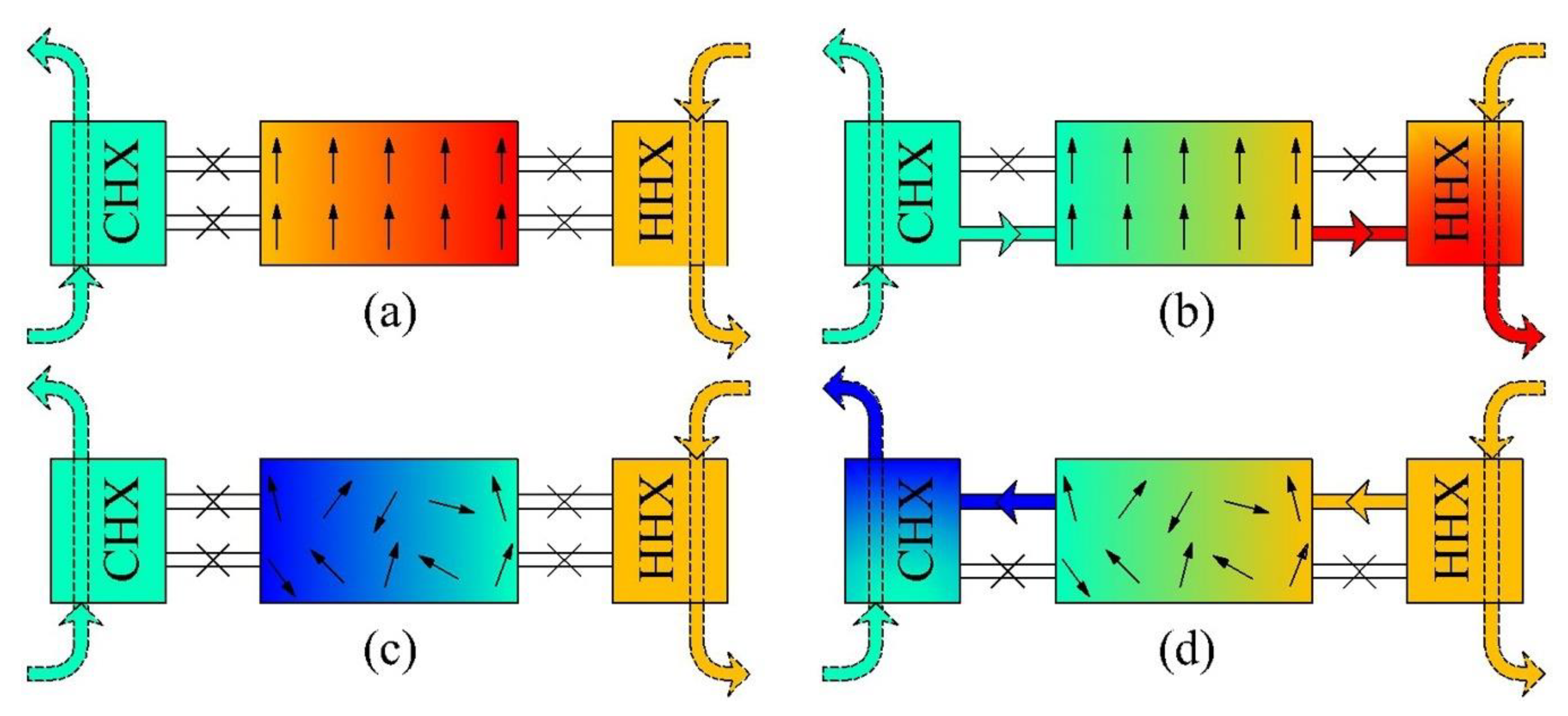
The magnetic refrigeration cycle consists of four stages—similar to the thermodynamic cycles of the compression refrigeration system. In
Figure 1, an outline of the active magnetic cooling system cycle is shown with a cold heat exchanger (CHX) and hot heat exchanger (HHX).
The magnetocaloric material with a constant initial temperature is exposed adiabatically to the external magnetic field, and its temperature increases according to the magnetocaloric effect (T + ).
The heat transfer fluid enters from the cold side and absorbs the heat of the solid refrigerant, thereby reducing the temperature of the solid refrigerant (T). The temperature of the fluid is increased due to the heat absorbed from solid refrigerant, so that the outlet temperature of the fluid in the hot end of the regenerator is increased and the heat is transferred to a hot heat exchanger or the environment.
The bed of the regenerator is demagnetized adiabatically, resulting in a decrease in the MCM temperature (T − ).
The working fluid exits from the cold heat exchanger and flows in the opposite direction in the regenerator bed (from the hot end to the cold end). The temperature of the fluid leaving the cold end is less than the refrigeration load temperature, which can absorb the cooling load from the cold reservoir (T). The temperature of the regenerator backing into it is the original temperature (the zero magnetic field), thereby the cycle is completed and commence from stage A.
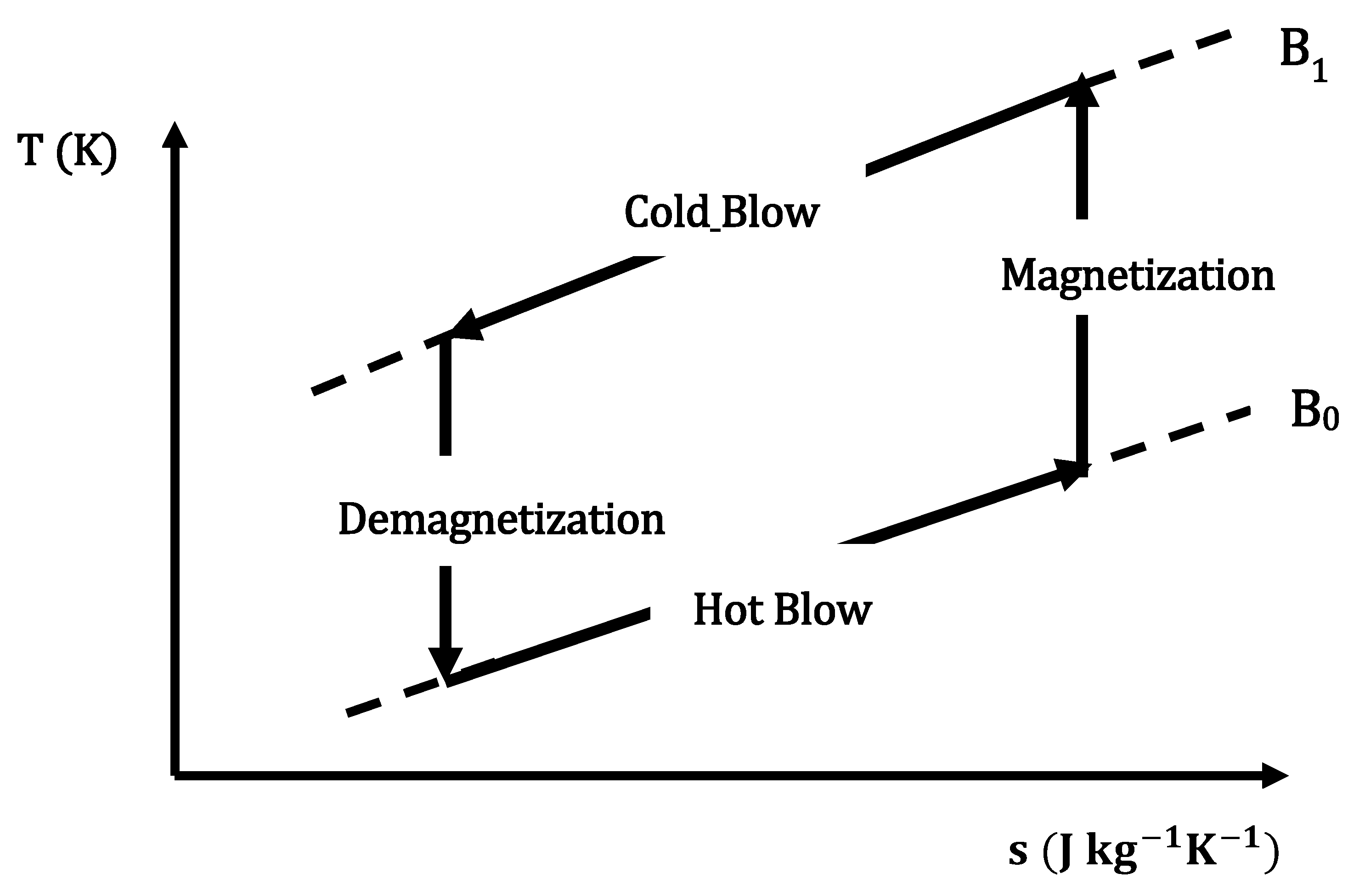
The temperature-entropy diagram is shown in
Figure 2. The processes of applying the on magnetic field and removing the magnetic field are assumed to be isentropic.
2.2. Governing Equations
By applying the first law of thermodynamics for the one-segment solid refrigerants (MCM) and heat transfer fluid (energy conservation equation), the energy equations of the regenerator and heat transfer fluid are derived as follows:
where
k,
T,
ρ,
c, and
s are the thermal conductivity, temperature, density, specific heat, and specific entropy, respectively, and
,
x,
t,
,
B,
, and
ε are the cross-sectional area, axial position, time, mass flow rate, magnetic field, heat transfer coefficient, and porosity, respectively. The subscripts
f and
s represent the fluid and solid refrigerant, respectively. The term on the right-hand side of Equation (1) represents the energy stored in the fluid. On the left-hand side of Equation (1), the first term describes the axial conduction, the second is the advection term, the third accounts for the convective heat transfer between the fluid and the solid, and the fourth accounts for the heat generated due to viscous dissipation. Similarly, in Equation (2), the right-hand-side term describes the energy storage in the regenerator bed. On the left-hand side, the first term represents the convective heat transfer between the fluid and the solid, the second term accounts for the axial conduction, and the third accounts for the MCE.
2.3. Modeling Conditions and Assumptions
In general, for analyzing of AMR mathematical models following assumptions had been considered:
2.3.1. Properties of the Magnetocaloric Materials
The properties of the magnetocaloric materials are of great importance in a magnetic refrigeration system. An inappropriate choice of the magnetocaloric material increases the cost and reduces the system efficiency. The magnetocaloric material also has a crucial impact on the MCE. Therefore, it is important to use the MCM material that is suitable for the particular application. Some of the most important materials used in near-room-temperature applications in the magnetic cooling system cycle have been found through research [
13]. A comprehensive review on a wide variety of magnetocaloric materials was reported in [
14]. In this study, it was shown that for low-temperature applications, Laves phases are employed for hydrogen liquefaction, and for room-temperature applications, Gd (and its compounds),
type phases and MnFePSi type phases are typically employed. It is notable that some materials (Heusler alloys) demonstrate giant MCE, but they have drawbacks such as significant magnetic hysteresis and slow transformation kinetics, which have rendered them less attractive for use in magnetic refrigeration devices. These problems could be eliminated, or their impact reduced by materials engineering processes. Good examples of these methods are the following: Multiphase materials and composites, fabrication techniques, powder metallurgy, nanostructures, and special treatment conditions (hydrogenation, annealing) [
14].
Magnetocaloric materials with high MCE are still in the development stage, requiring more investigation and the design of solid refrigerants suitable over a wide working temperature. Rare earth (RE)-based intermetallic compounds are promising materials which manifest a significant MCE. The properties and MCE of RE-based intermetallic compounds depend on the crystal structure, magnetic properties, and magnetic phase transition. The RE-based intermetallic compounds can be stratified into three categories: Binary, ternary, and quaternary compounds. It was indicated that by modification of the concentrations and physical properties of these compounds, a reasonable MCE with a wide range of working temperatures is achievable [
15].
RE-based intermetallic compounds (
) are practical at low temperatures and can, therefore, be used in cryogenic applications. A number of magnetic refrigerants with excellent cryogenic magnetocaloric properties were summarized in [
16], which also briefly reviewed RE-based intermetallic compound materials with a substantial MCE in low magnetic fields. In addition, it was shown that magnetic properties and magnetic entropy changes could be modified by applying hydrostatic pressure.
In this study, a single layer of Gd was used as a refrigerant. Gadolinium is one of the MCM materials which has widely been used in magnetic refrigeration for near-room temperature applications. The MCE of pure gadolinium near room temperature is around 293 K. In addition, the properties of gadolinium are fairly acceptable (
) at a magnetic field change of 1 T [
17]. Its properties have made it an ideal reference candidate to compare to other different MCM materials in magnetic refrigeration applications. However, two of the main drawbacks when choosing Gd are its purity and price, which could limit its applications. In spite of these challenges, its MCE properties and lack of magnetic hysteresis make it the first choice for room-temperature magnetic refrigeration. The properties of MCM were obtained with respect to the mean field theory (MFT); a more complete description of the mean field theory was presented in a study by Petersen [
18]. According to the mean field theory the magnitude of the entropy changes with magnetization is predictable. The thermodynamic properties of the MCM can be obtained by the MFT for a wide range of temperatures and magnetic fields.
Figure 3a shows the isothermal entropy change in the MCM during the magnetization of pure gadolinium when it is magnetized from 0 to 1.5 Tesla. Entropy changes are shown in two manners: Experimentally [
10] and the MFT. As can be seen, there are differences between the MFT and experimental data. The Curie point was predicted by the MFT to be sharp point and well-defined, while in the experimental curve, it is smooth. The entropy changes at temperatures below the Curie temperature in the MFT are more than the experimental values, while above the Curie point a good agreement is found between the experimental results and the outcome of the MFT.
These discrepancies can be explained by the following reasons. Firstly, due to the impurities in gadolinium which are observed in experimental tests, its entropy changes are less than those predicted by the mean field theory. Secondly, the MFT over-estimates the values and is too idealized. Thirdly, it was assumed that the MCM material was uniformly distributed throughout the material, while in the real model this was not possible. Although there is a difference the between numerical and experimental results, the MFT method is an efficient for modeling the properties of a magnetocaloric material. Not only does it predict the properties of magnetocaloric materials in the steady state at wide temperature ranges and magnetic fields, but it also removes some of the issues associated with experiments.
Figure 3b shows the entropy changes at different temperatures and magnetic fields from zero to 1 T and compares these to the results reported in [
18]. As can be seen, there is a good agreement between the two works. The properties of MCM were obtained in [
18] by MFT.
2.3.2. The Type of Magnetic Refrigeration System
The first magnetic prototype was built in 1976 by Brown [
17], and a wide range of different prototypes have been designed and built over the 40 years since. There is a one feature that plays an important role for all these prototypes. This feature classifies devices into two groups which are a reciprocating (linear motion) manner and a rotary manner. The reciprocating motion means that the AMR system or the magnet moves in a reciprocal direction back and forth, and in the rotary system, the AMR or magnet is rotating. Each of these methods has its advantages and disadvantages, and the appropriate choice depends on the purpose of the prototype. One of the considerable drawbacks of reciprocating systems is that the operating frequencies are limited to ≤1 Hz, which could influence the refrigeration capacity, there is no frequency limitation in the rotary system. However, reciprocating devices are still practical as experimental testing devices compared to rotary system.
On the other hand, there are two main problems associated with the rotary system. The first issue is in the assembly of AMR and magnet systems, and the second, in the auxiliary components, such as the heat exchanger and heat-transfer fluid system. However, most rotary devices, as can be expected, work more efficiently as they operate continuously compared to a linear device, which does not.
In a study performed by Yu et al. [
19], different types of magnetic refrigerators and heat pumps with different geometries were investigated. In the present study, the rotary system that was published by Zimm et al. [
20] was chosen.
2.3.3. The Other Simplifying Assumptions
It was assumed that there is no phase change occurs in the heat transfer fluid, to prevent the freezing of water, a mixture of water and 10% ethylene glycol was used as a heat transfer fluid.
The fluid heat transfer was assumed to be incompressible (constant density). Among the properties of the heat transfer fluid used in the modeling of the magnetic cooling system were the viscosity, thermal conductivity coefficient, and heat capacity. Fluid properties were considered to be a function of temperature; therefore, the properties of the fluid were considered as a polynomial function of the temperature.
There is no flow leakage during the cycle which is an ideal assumption. It may be difficult to control the flow leakage during experiments.
The radiation heat transfer is negligible compared to the convective and conductive heat transfer which is a good approximation in room temperature applications.
It was assumed that the solid material is distributed uniformly in the regenerator. This assumption is not applicable in the experimental models.
One possible way to predict the initial distribution temperature of the fluid and the regenerator is to extrapolate them from the linear profile.
Regardless of magnetic hysteresis, the on and off magnetic fields are assumed to be adiabatic and reversible processes. When the magnetic field is removed completely or reaches the zero value, the temperature of the magnetocaloric material returns to its original (initial) state.
2.4. Selecting Regenerator Geometry
Selection of the regenerator geometry, namely, the main parameter that determines the performance of the magnetic refrigeration system, was considered. In a study on various geometries of the magnetic refrigeration system [
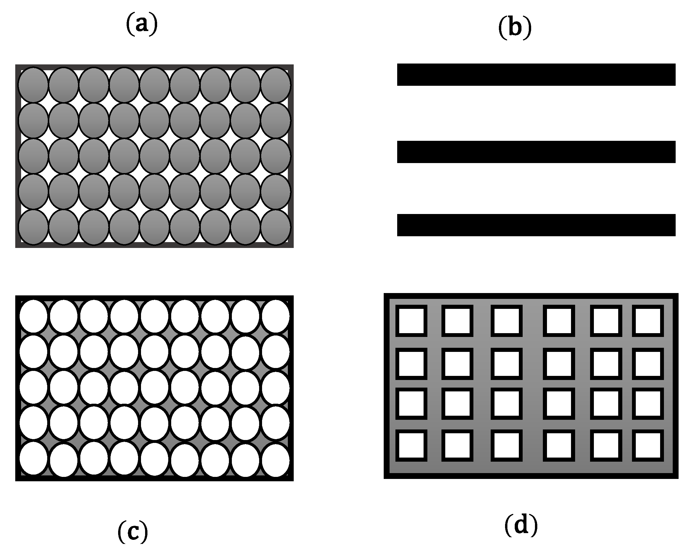
7], parallel flat plates and microchannel matrices were found, theoretically, to have the highest efficiency; however, it was found that it is possible to use a packed sphere bed in applications. The spherical particle bed characteristic is the spherical particle diameter, in which the same or different particle diameters can be considered. In this study, the sphere particle diameters were considered to be the same. A schematic of the various regenerator geometries is shown in
Figure 4. In
Figure 4, the dark-colored regions represent solid matter and white areas indicate the heat transfer fluid that is normal for the case of a sheet of paper.
The correction of the pressure drop for spherical particles is as follows [
21]:
In the pressure drop equation for spherical particles, the velocity of the fluid is obtained by dividing the volumetric flow rate (Q) of the fluid over the cross-sectional area of the regenerator. In addition,
dp is the particle diameter, and the porosity (
) is considered to be 0.362. The specific cross-sectional area is given in Equation (4):
The Nusselt number for packed sphere nodes was presented by Wakao and Kaguei [
22]:
To calculate the thermal resistance of spherical particles, Equation (5) was modified to give Equation (6) [
23,
24]:
where
and
are the effective thermal conductivity for the fluid and magnetocaloric material, which are presented by Equations (7) and (8) [
25]:
The temperature range
was calculated according to the difference between the hot- and cold-source temperatures.
is the temperature of the cold source and
TH is the hot source temperature. The refrigeration capacity and heating load were calculated according to Equations (9) and (10), and the COP was calculated according to Equation (11):
where
τ,
t, and
are the cycle period, time, and mass fluid flow rate, respectively.
and
are the enthalpy of the output fluid from the cold and hot ends of the regenerator at any time step. The temperature of the fluid at the time it entered the cold and hot ends of the regenerator was assumed to be equivalent to the cold- and hot-source temperatures, respectively. The heat conduction in the ends was neglected. The positive mass flow rate is defined when the fluid flows from the cold end to the hot end of the regenerator and the negative mass fluid flow rate is defined as the reverse. The boundary conditions of the regenerator are shown in Equations (12) and (13) in accordance with the fluid flow direction:
The governing Equations (1) and (2) are solved numerically using the finite differences method. The fluid and regenerator energy balance from Equations (1) and (2) are discretized and provided for each control volume. It is assumed that the fluid and MCM properties in each time step are constant. In other words, there are no significant changes in the fluid and MCM properties in each time step. The fluid and MCM temperatures at each point in the time step will be obtained by solving the discretized equations for the previous time step. The discretized forms of the fluid and regenerator energy equations are solved by assuming an initial temperature, and the fluid and regenerator temperatures are obtained at the next time step. Discretized equations were iteratively solved, and the iteration process continued until the fluid and regenerator temperatures between repetitions remained unchanged. Since in numerical solutions, the contiguous space becomes discrete, one of the important advantages of this method is that it is independent from computational networks. It is essential to choose a grid which is not dependent on the number grids to accurately predict the performance of the AMR. To determine the sensitivity of the numerical model from the number of time steps and axial nodes, grid sensitivity analysis was performed. The independence of the results from the number of computational nodes and the disjoint of temporal steps are indicated in
Figure 5 and
Figure 6, respectively. These figures represent refrigeration capacity (Qc) based on the number of axial nodes and time steps. In the numerical model, the number of time steps and axial points in the longitudinal direction (the spatial node) were considered to be 8000 and 60, respectively. The parameters used in the grid study were a frequency of 4 Hz, mass flow rate of 3
, porosity of 0.362, and sphere diameter of 0.5 mm. The hot and cold reservoirs temperatures were 286 and 283 (K), respectively.
2.5. The Heat Transfer Fluid
The heat transfer fluid has an important role in the performance of the AMR. It should have acceptable thermodynamic properties, i.e., high thermal conductivity and low viscosity. These characteristics are significant at high operation frequencies. The majority of AMR systems use water as a heat-transfer fluid. The advantage of water is that it has good properties, is non-toxic and highly available. The disadvantage of using water is that it can cause corrosion of the magnetocaloric materials and also turn into the solid phase below 0 °C. A solution to this is the use of a mixture of anti-corrosives and anti-freeze with water (e.g., at a ratio of 20:80), this can not only prevent corrosion, but also decrease the freezing point of the mixture to below 0 °C. The impact of the heat-transfer fluid on the AMR performance is undeniable. Numerical, experimental, and theoretical studies have been performed on AMR performance [
17]. In [
17], they compared four types of heat-transfer fluid: Water, liquid metals, different alcohols, and different mixtures of water and ethanol. The results showed that liquid metals had the best cooling properties, while pure water yielded the best AMR performance. In spite of the fact liquid metals (e.g., gallium) have a better performance compared to the other fluids, they may be highly toxic and, therefore, cannot be used as the working fluid in a magnetic refrigeration system. They also often have high densities or viscosities, which results in viscous dissipation.
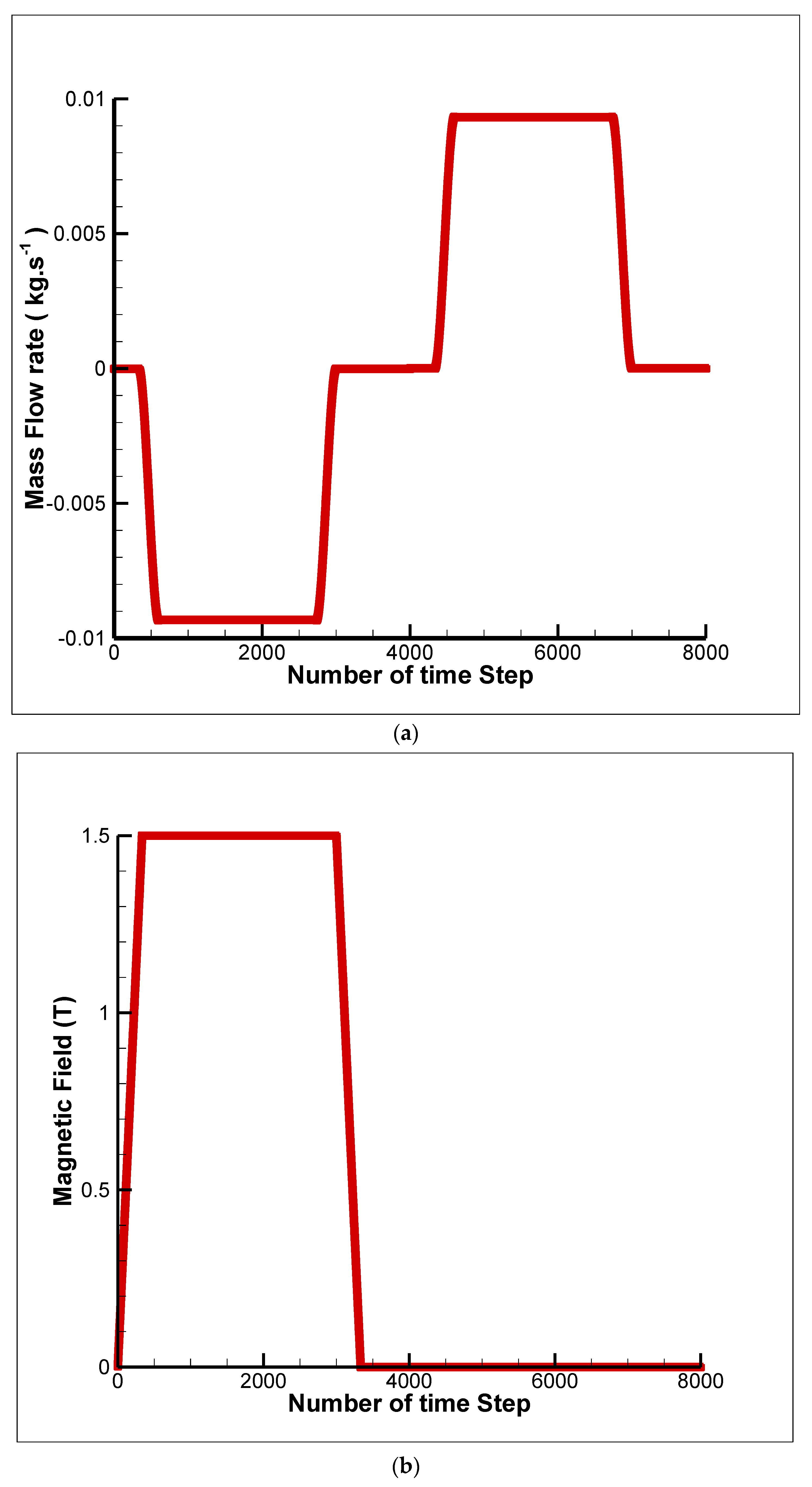
Generally, the distribution of fluid flow in all numerical models is assumed to be a periodic fluid flow as a function of time. There are two methods to assume the mass flow rate profile, a discrete mass flow rate profile through a ramping method (an appropriate function) and a continuous flow curve (sinusoidal or hyperbolic tangent) [
9]. Discrete mass flow rate profiles were determined to be the best choice because they eliminate some of the errors which originate from specific experimental devices [
9]. The function of the mass fluid flow is shown in
Figure 7a.
2.6. The Magnetic Field
With respect to the magnetic field, the same method that was used for the mass flow rate profile can be considered for the magnetic field distribution. For the numerical model to resemble the experimental model, the function of the magnetic field could be performed through a number of time steps.
Figure 7b shows the function of the magnetic field during a cycle.
The parameters considered in the numerical model are presented in
Table 3. In this model, the intensity of the magnetic field and the dimensions of the regenerator geometry were considered to be constant. The other parameters were changed to evaluate the effect on the performance of the magnetic refrigeration system. The refrigeration capacity, heating load, and COP were defined as positive.
2.7. Validation
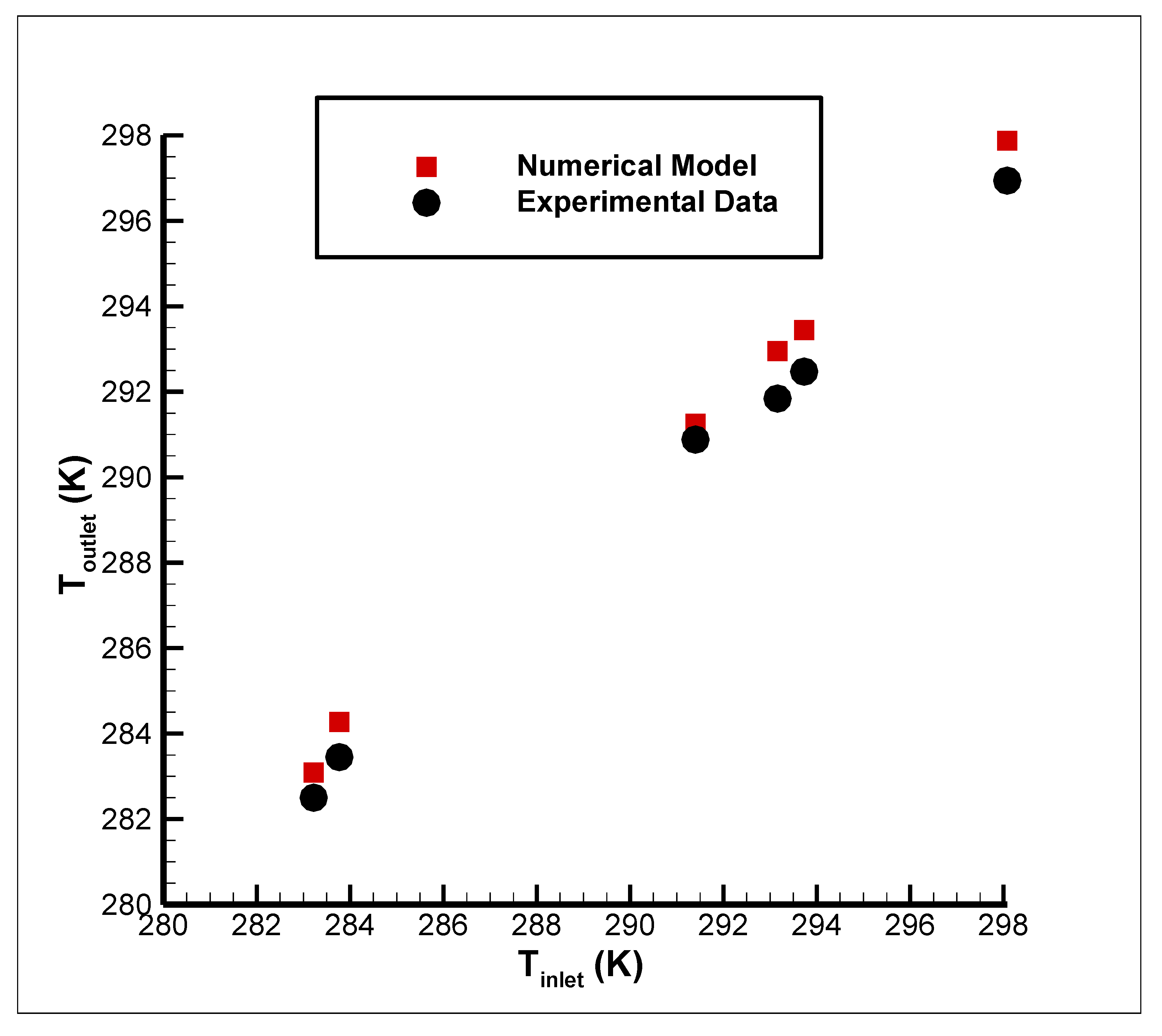
After the grid study for the numerical model described in the previous section was performed, the numerical model was validated by the experimental data. The results of this study were compared with those of a laboratory study [
10]. The outlet temperature of fluid from the cold end of the regenerator (T
outlet) was obtained at the demagnetization step at a frequency of 1 Hz. The inlet temperature was equal to the temperature of the cold reservoir. The diameter of the spherical particles was 0.5 mm, and the porosity was 0.362 for different mass flow rates (
Figure 8).
3. A Study of the Parameters That Effect System Performance
Initially, the effect of the mass flow rate on the output of the model, including the refrigeration capacity and coefficient of performance, was investigated in different working conditions. In addition, the effect of different parameters on the performance of the magnetic refrigeration system was shown. Design charts were based on the coefficient of the performance and refrigeration capacity of the magnetic refrigeration system.
3.1. Fluid Flow Rate
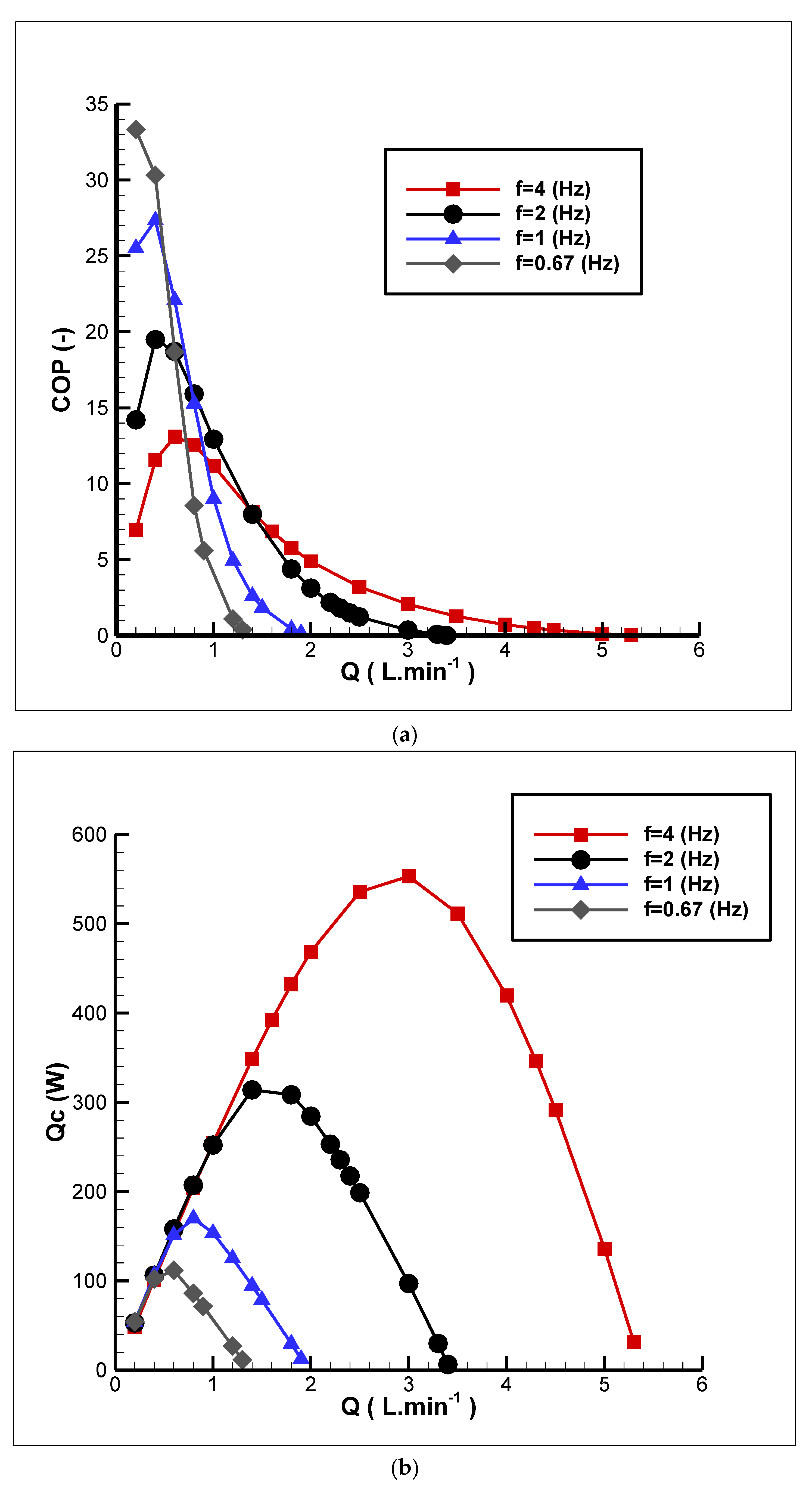
The effect of the mass fluid flow rate parameter was investigated, and the other parameters were assumed to be constant. By increasing the mass flow rate of the fluid, the heat transfer between the fluid and the magnetocaloric material increased because more heat is absorbed by the fluid. Therefore, the coefficient of performance and refrigeration capacity increased. Furthermore, by increasing the mass flow rate of the fluid, the viscous dissipation increased and produced heat in the fluid. Increasing the heat transfer rate between the fluid and the magnetocaloric material compensated for this so that the mass flow rate of the fluid could achieve an optimum value. From this point on, by increasing the mass flow rate of the fluid, the viscous dissipation had a greater effect than the increase in the heat transfer rate between the fluid and the solid refrigerant, causing the coefficient of performance and refrigeration capacity to decrease overall (
Figure 9). By plotting a horizontal line parallel to the horizontal axis, the graph was disconnected at two different points. This meant that the refrigeration capacity and coefficient of performance were proportional to the two different mass fluid flow rates. It is important to note that the viscous dissipation of the fluid for the lower mass fluid flow rate was lower than that in the higher mass flow rate. Thus, it is important to ensure that the fluid flow rate is either too low or too high.
Table 4 shows the parameters that were considered to evaluate the effect of the volumetric flow rate.
3.2. Frequency
As shown in
Figure 9, the refrigeration capacity and coefficient of performance increased with decreasing frequency at a low flow rate because the heat transfer time between the fluid and the magnetocaloric material increased. At high volumetric flow rates, by increasing the frequency, the number of cycles completed at the time step increased, which increased the refrigeration capacity and the coefficient of performance. As it observed, higher frequencies are achievable in higher mass flow rates and, therefore, it would result in higher viscous dissipation and consequently, higher input pump work was required that reduced the overall performance.
3.3. Temperature Span (Hot- and Cold-Source Temperature Difference)
The temperature span is another important design parameter. In this study, the effects of the temperature span variation on the refrigeration capacity and coefficient of performance were evaluated and the results are shown in
Figure 10. According to
Figure 10, it can be concluded that the refrigeration capacity and coefficient of performance were inversely proportional to the temperature range. In the low-temperature span, due to the fact that less power and energy are needed to transfer heat from a cold source to a hot supplier, it was expected that the refrigeration capacity and coefficient of performance would be higher than in the higher temperature span. Hence, the refrigeration capacity and the coefficient of performance decreased by increasing the temperature span. As the temperature span increased due to the axial heat conductivity from the hot end to the cold end of the regenerator, heat loss is increased, and it would result in reducing the overall efficiency.
3.4. Spherical Particle Diameter
One of the key parameters of the packed sphere bed regenerator is the size of the spherical particle diameter, as shown in
Figure 11. By increasing the diameter of the spherical particles, the refrigeration capacity and the coefficient of performance first increase and then decreased meaning that there will be an optimal diameter for the spherical particles. Below the optimal diameter of spherical particles, increasing it reduces the viscous dissipation, thereby increasing the refrigeration capacity. On the other hand, beyond the optimal diameter of spherical particles, increasing it results in a decrease in the coefficient of the heat transfer and, therefore, the coefficient of performance and the refrigeration capacity decrease.
3.5. Porosity
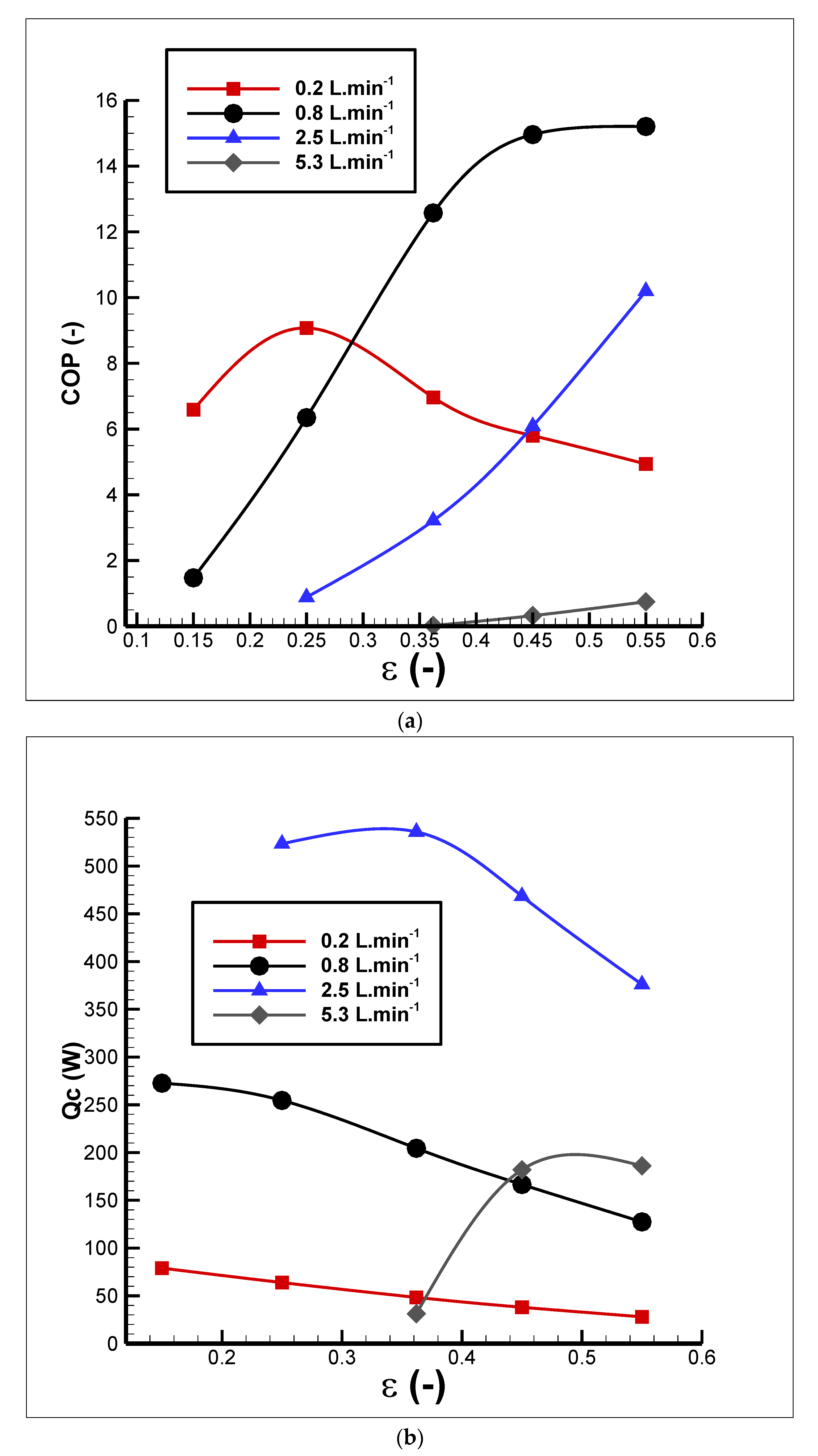
Porosity is defined as the ratio of the volume of empty space to the total regenerator volume. By increasing the porosity, the free space of regenerator increases, therefore more fluid can pass through the regenerator bed and more heat is absorbed from the solid refrigerant, leading to an increase in the refrigeration capacity and the coefficient of performance. On the other hand, an increase in porosity reduces the amount of magnetocaloric material and the magnetocaloric effect, thereby reducing the refrigeration capacity and coefficient of performance. In this case, a more intense magnetic field can be used to increase the refrigeration capacity and coefficient of performance. Furthermore, it should be noted that in a very-low-porosity condition, the viscous dissipation is increased, so that a lower refrigeration capacity and coefficient of performance can be expected (
Figure 12).
3.6. Pump Power
One of the most important parameters influencing the performance of the magnetic refrigeration system is the pump power, that is, the viscous dissipation. Viscous dissipation in the fluid is the irreversible process which causes mechanical energy to transform into heat and may increase the heat losses. The impact of the viscous dissipation is included in the AMR model via a friction factor, as shown in Equation (3). The effect of viscosity loss at high frequencies will increase and, in some cases, become significant in the models of compact AMRs, because the small geometries require higher fluid flow to maintain the same cooling capacity at a large scale. Excessive pressure drops (viscous dissipation) increase the work required to pump the fluid through the AMR.
In this study, it was assumed that there is no leakage in the system, and the mechanical parts of the system such as the piping system were not considered in the numerical model. The impact of these parameters on the performance of the AMR could be considered as a correction factor to the pump power.
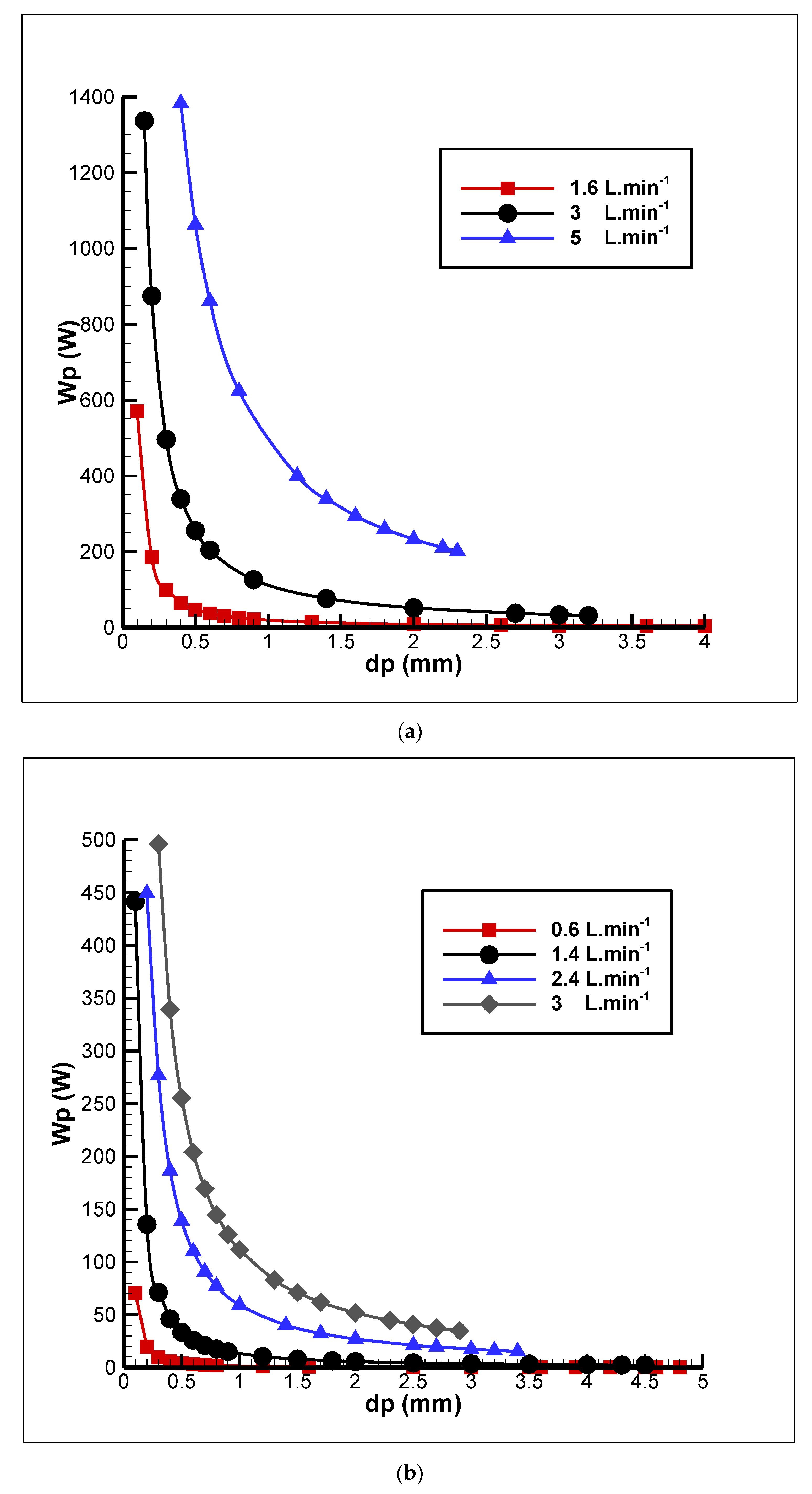
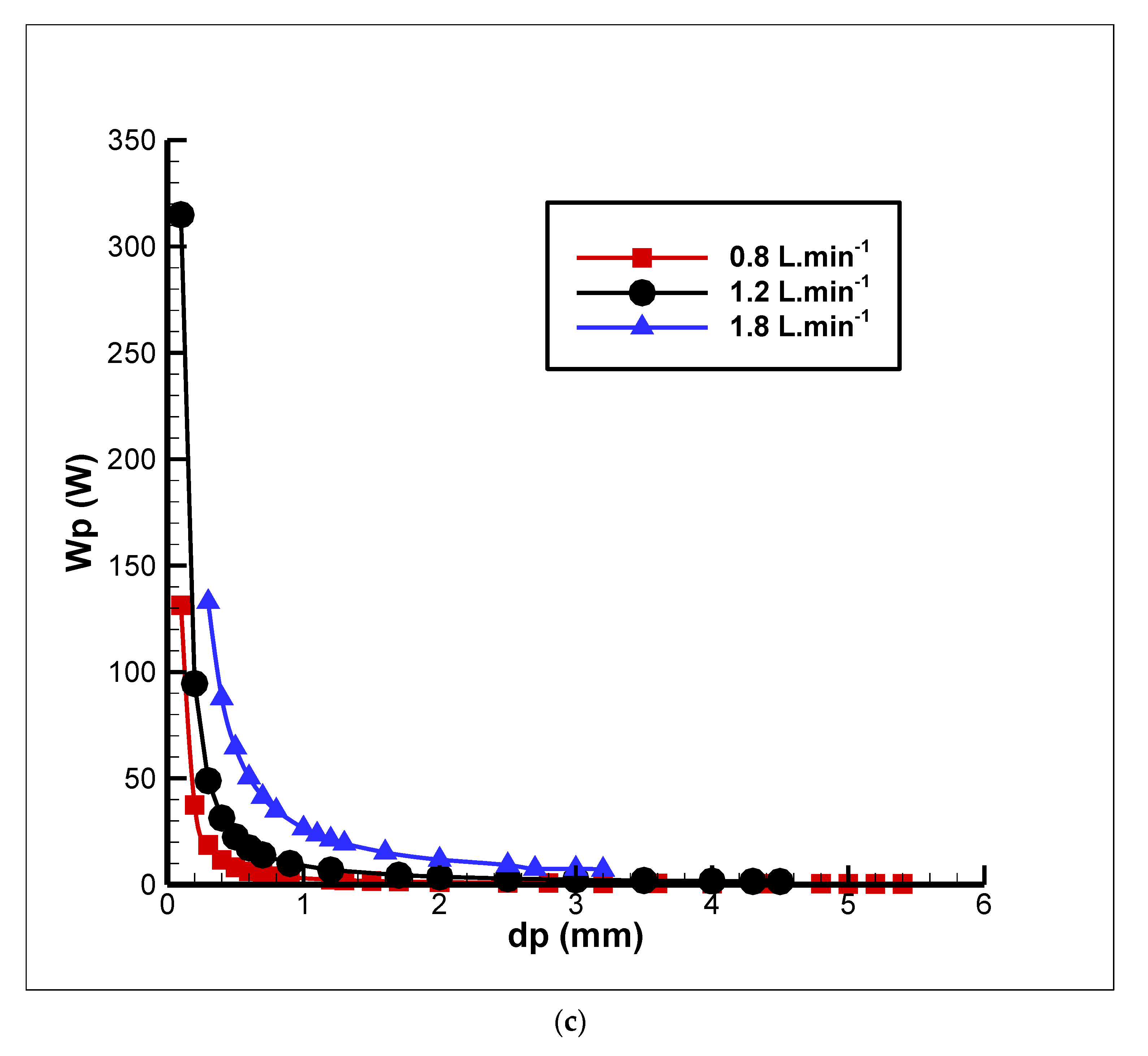
An important parameter in the viscous dissipation is the spherical particle diameter. As shown in
Figure 13, the work of the pump was increased due to the increased pressure drop by reducing the diameter of the spherical particles and increasing the mass flow rate of the fluid.
3.7. Design Analysis
Figure 9,
Figure 10,
Figure 11,
Figure 12 and
Figure 13 show the effect of different parameters on the performance of the magnetic refrigeration system. The performance of the AMR considerably depends on the operational parameters.
Figure 9 shows that low or high mass flow rate is not desirable for the AMR and by increasing the frequency cooling power will increase. The results which are presented in
Figure 10 show that there is a linear dependency of COP and refrigeration capacity on the temperature span.
Figure 11 shows the refrigeration capacity and COP as a function of sphere diameters. It is evident that there is an optimum point for sphere diameter for each mass flow rates. The effect of diameter of spherical particles and mass flow rate simultaneously on AMR performance in are presented in
Figure 13.
The designer of a new magnetic refrigeration system can select the parameters that are appropriate for the working conditions by using the diagrams presented in this study. According to the parameters reported in
Table 3, it is possible to predict the third parameter by having two parameters. For example, as shown in
Figure 9, the refrigeration capacity and the coefficient of performance can be calculated by using the flow rate and operating frequency. Furthermore, using the frequency and the refrigeration capacity, it can be predicted how much refrigeration capacity is being met at a specific rate of mass fluid flow. In the same way, like the other parameters, the porosity, temperature range, and diameter of the spherical particles can be calculated. Design charts can be categorized into different groups: The design diagram based on the operational parameters, the price of the magnetocaloric material, the dimensions, and geometry of the regenerator. Design charts can be considered as a tool for developing a magnetic refrigeration system without performing mathematical calculations that leading to time-saving. The designer of the cooling system must be aware of the application of the system and understand what the purpose and operating conditions related to the system are and consider all the aspects of their designs, including the limitations, designers must also offer all possible options for the client’s system requirements. Some of the losses in the magnetic refrigeration system that affect the AMR performance are the insufficient heat transfer between the heat transfer fluid and the magnetocaloric material, the magnetic hysteresis, insufficient heat transfer in heat exchangers, and the pressure drops in the piping and heat exchanger. Another important point that should be considered in the system design is the desired economics of the refrigeration system, that is, having the lowest cost and the highest efficiency. The basic information generally required in order to design an active-reactive magnetic refrigeration system is shown in
Table 5.
4. Conclusions
In this study, the effect of different parameters, such as the fluid flow rate, porosity, spherical particle diameter, temperature span, and frequency, on the active magnetic refrigeration system was evaluated. As a result, the optimal parameter was obtained in each working condition. In this research, it was shown that the temperature span is inversely related to the refrigeration capacity and coefficient of performance. At high-fluid-flow rates, increasing the frequency makes it possible to increase the coefficient of performance and refrigeration capacity. The spherical particle diameter is one of the parameters that influence the performance of the magnetic refrigeration system, which is inversely related to the pressure drop. Therefore, by conducting a parametric study on the mass flow rate of the fluid and the diameter of spherical particles in each working condition, the pressure drop can be controlled and evaluated. In this study, an efficient numerical method is proposed that reduce the computational time and minimize numerical errors.
The study showed that the magnetic refrigeration system efficiency is highly dependent on the selected parameters. According to the refrigeration capacity and coefficient of performance, the designer of a magnetic refrigeration system can extract the required parameters from the design charts. Design charts and tables are of particular importance for the design of a magnetic refrigeration system because of their time-saving capacity. Furthermore, without having to make complex calculations and creating additional costs, the desired parameter can be selected from the tables and design charts. Some of the items to be monitored that should be considered in designing a magnetic refrigeration system are presented in
Table 5.
The limitations of this study include the lack of laboratory equipment to accurately measure the properties of the magnetocaloric material and build a prototype of AMR model. Some errors in system modeling are due to the assumptions of a uniform distribution of fluid flow in all regenerators, that there is no leakage in the system and there is no detectable magnetic hysteresis. These items are difficult to implement in the experimental model, which results in a discrepancy between the numerical model and experimental data, and leads to an overestimation of the outputs of the numerical model. AMR modeling is an immature field and requires further detailed research. Using new methods to calculate the actual magnetic field would result in customer demands being met with higher accuracy.
