Abstract
In the five-phase permanent magnet synchronous motor (PMSM) control system, the torque ripple caused by coil inter-turn short-circuit (ITSC)fault will make the motor performance worse. Due to the existence of the short-circuit current in the faulty phase and the third harmonic component in the permanent magnet flux linkage, the electromagnetic torque will contain even-order ripple components when the faulty phase is removed. Torque ripple also cause speed ripple. In this paper, the repetitive controller (RC) is used to perform proportional gain compensation for speed ripple. By designing the RC and connecting RC and proportional integral (PI) controller in parallel for the speed loop, the torque ripple amplitude can be reduced. It can be seen from the simulation and experimental results that the torque ripple suppression strategy based on RC can effectively suppress the torque ripple under ITSC fault.
1. Introduction
Permanent magnet synchronous motors (PMSMs) have the advantages of high efficiency, high torque density and good control performance [1,2,3,4]. Compared with traditional three-phase PMSMs, multi-phase PMSMs have fault tolerance. Increasing the number of phases of PMSM can makes the motor control method more flexible, and different voltage vectors can be used to synthesize the reference voltage [5,6,7]. Since the motor has more control degrees of freedom, when the fault occurs in phase winding, the remaining healthy phases can be used to achieve fault-tolerant operation [8,9]. Because of this advantage, multi-phase PMSMs are widely used in occasions with high reliability requirements. The common faults in the stator windings of PMSMs include open-circuit fault and short-circuit fault and inter-turn short-circuit (ITSC) faults are more common and tricky. The main objective of this paper is to study the fault-tolerant method of ITSC fault in a five-phase PMSM.
ITSC fault have the following adverse effects on the PMSM: irreversible demagnetization of permanent magnet, heat generated by the short-circuit current on the motor, ripple of electromagnetic torque [10]. In order to limit the short-circuit current, sufficiently high inductance must be designed [11]. When designing the motor, the stator adopts the fractional-slot concentrated-winding, the suitable pole-slot matching and the special stator core structure. In this way, the designed motor has the characteristics of low thermal coupling and no electromagnetic coupling among phase windings [12]. When short-circuit fault occurs in the motor, the magnetic field generated by the short-circuit current will not be interlinked with the remaining healthy phase windings, and the fault tolerance performance can be improved. Diagnosing ITSC faults in time can prevent further aggravation of short-circuit faults [13,14,15]. Therefore, short-circuit fault diagnosisis also an important research direction.
In order to improve the performance under ITSC fault conditions, reconstruction of fault-tolerant control strategies under fault is a main method. In Ref. [16], for the overall short-circuit fault of one phase, a compensation current is added in the way of voltage feedforward compensation to eliminate torque ripple. However, this method focuses on the whole short-circuit fault of one phase winding, and the short-circuit current is measured. Since the short-circuit current and the short-circuit location are unknown, this method is not applicable to coil ITSC fault. In Ref. [17], for the open-winding five-phase PMSMITSC fault, the compensation current is calculated by detecting the zero sequence current and the faulty phase voltage to suppress torque ripple. Since this method needs to detect faulty phase voltage, it is difficult to use for five-phase PMSM with star-connected stator windings. In Ref. [18], a short-circuit fault tolerance method for dual-redundancy motors is introduced. After a short-circuit fault occurs, the motor runs in the single redundancy mode. By connecting adaptive PR controller and PI controller in parallel, the torque ripple suppression effect at different speeds can be achieved. However, in order to suppress torque ripple at multiple frequencies, multiple PR controllers need to be connected in parallel. This increases the complexity of the control system. In Ref. [19], the relationship between negative sequence current and torque ripple is given in internal turn short fault. The influence of negative sequence current is eliminated by using positive and negative sequence current regulators in this paper. But this is for the case of three-phase motor short circuit. In multi-phase motors, it is difficult to extract positive and negative sequence currents. In Refs. [20,21], these control methods can make the motor maintain better control performance when it is open. They have important reference values for the open-circuit control mode of the motor after short circuit. However, these methods are ineffective in suppressing the torque ripple caused by the short-circuit current. In Ref. [22], ITSC faults are analyzed by taking afractional slot concentrated winding interior PMSM as an example. The variations of phase currents, short-circuit current, torque, temperature and other variables are compared under normal operation and ITSC fault. In the reference, six-step square-wave control method and field-oriented control method are used, and the variations of various parameters are compared through simulation and experiment. Since the current controller is used in field-oriented control mode, the stator current harmonics and torque ripple under ITSC fault is smaller than the six-step square-wave control mode. Therefore, field-oriented control method can reduce the impact of ITSC fault.
In order to reduce the torque ripple in ITSC fault, this paper proposes a method of connecting repetitive controller (RC) and proportional integral (PI) controller in parallel. RC will perform proportional gain compensation on speed ripple components. Compared with other fault-tolerant control methods, this method does not require additional sensors. There is no need to know the magnitude of the short-circuit current. The discrete model of the control system is established in the paper. By analyzing the fault-tolerant control system, the torque ripple can be suppressed after adding RC. Taking a five-phase PMSM as an example, this paper verified the control effect through simulations and experiments.
2. The Structure of Five-Phase PMSM
The cross-sectional diagram of five-phase PMSM and the outspread diagram of stator windings with low thermal coupling and no electromagnetic coupling among the phase windings are shown in Figure 1 and Figure 2.
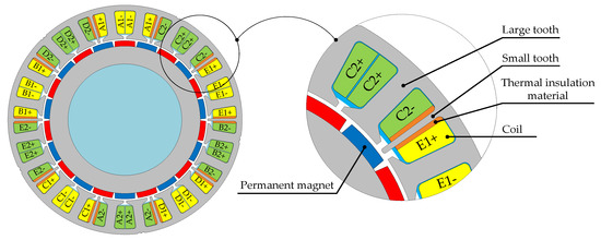
Figure 1.
The cross-sectional diagram of the five-phase PMSM.
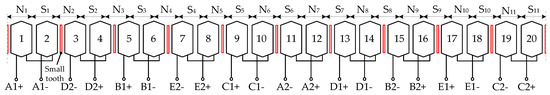
Figure 2.
The stator windings outspread diagram of the five-phase PMSM.
The proposed five-phase PMSM is evolved from the conventional fractional-slot concentrated-winding 20-slot/22-pole five-phase PMSM. By adopting a winding structure with positive and negative coils, the armature reaction inductance between windings of different phases can be eliminated. But there is still slot leakage mutual inductance between adjacent phase windings. By adding small teeth in the common slots among different phase windings, there is no electromagnetic coupling between the phase windings. And the mutual inductance is almost zero [12]. The thermal insulation materials are placed on both sides of small teeth to reduce thermal coupling between adjacent phase windings. The structure of low thermal coupling and no electromagnetic coupling between the phase windings improves the fault tolerance of the motor.
The motor rotor adopts a surface permanent magnet structure. In order to increase the power density of the motor during non-fault operation by injecting the third harmonic current, in the motor design process, the permanent magnet magnetic field contains a certain third harmonic component. There are 10 winding branches on the stator, namely A1, B1, C1, D1, E1, A2, B2, C2, D2, and E2. The two winding branches of each phase have the same induced electromotive forces (EMF), which are connected together through the series structure, and the five-phase windings are connected in a star shape.
3. The Mathematical Model of Five-Phase PMSM
Because the motor has the characteristic of no electromagnetic coupling between the windings of each phase, there is no mutual inductance between the adjacent phase windings. When the motor is running normally, the voltage equation and flux equation in the five-phase stationary coordinate system can be expressed as:
where , , and are the phase voltage vector, phase current vector, phase winding flux vector and phase winding permanent flux vector respectively; R and L are stator resistance and inductance respectively. The initial position of the rotor is selected as the direction in which the direct axis (d axis) of the rotor coincides with the axis of the A-phase winding. Since the permanent magnet flux contains the third harmonic component, the five-phase permanent magnet flux matrix can be expressed as:
where and are the amplitudes of the permanent magnet fundamental flux linkage and the third harmonic flux linkage respectively; is the electrical angular velocity of the rotor.
When the five-phase PMSM is operating normally, the EMF of each phase windings can be expressed as:
The electromagnetic torque is as follows:
where is the electromagnetic torque; is the electromagnetic power; Ω is the mechanical angular velocity; p is the number of pole pairs.
In order to simplify the mathematical model of the five-phase motor and make it have a control method similar to a DC motor, the voltage Equation (1) is transformed by Clark transformation and Park transformation, and the voltage equation under the synchronous rotating coordinate system is obtained as:
where the subscripts d or q represent the direct axis (d axis) component and quadrature axis (q axis) component respectively; the subscripts 1 or 3 represent the fundamental component and the third harmonic component respectively. The electromagnetic torque in the d-q coordinate system can be expressed as:
4. Analysis of Torque Ripple in the ITSC Fault
When the ITSC fault occurs in the A-phase winding of a five-phase PMSM, the control system should cut off the A-phase and use the remaining four phases to continue operation through fault-tolerant control. At this time, the A-phase winding current . However, the rotating permanent magnet rotor induces EMF in the short-circuit coil and generates the short-circuit current. The equivalent circuit when short-circuit fault occurs between coil turns is shown in Figure 3. In the figure, and are the short-circuit resistance and the contact resistance at the short-circuit coil respectively; is the self-inductance of the short-circuit coil; is the EMF induced by the permanent magnetic field in the short-circuit coil; is the short-circuit current.
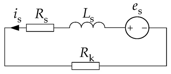
Figure 3.
Equivalent circuit of short-circuit coil when short-circuit fault occurs.
Since the permanent magnetic field contains the fundamental component and the third harmonic component, when other high-order harmonic components are ignored, the EMF induced by the permanent magnetic field in the short-circuit coil can be expressed as:
where and are the effective values of the fundamental and third harmonic EMF in the short-circuit coil respectively; and are the initial phase angles of the fundamental and third harmonic EMF in the short-circuit coil respectively.
The short-circuit current in the short-circuit coil contains fundamental and third harmonic components, and its equation is:
where and are the effective values of the fundamental and third harmonic components of the short-circuit current respectively; and are the fundamental and third harmonic impedance angles in the short-circuit loop respectively.
According to the principle of electromechanical energy conversion, the electromagnetic torque generated by the short-circuit current is:
It can be seen from Equation (10) that in addition to the constant component, the torque generated by short-circuit current also contains the ripple components of the second order, the fourth order and the sixth order. In this paper, the torque ripple component generated by the short-circuit coil is denoted as Tsf. The torque ripple component will cause adverse effect in the fault-tolerant control of the five-phase motor.
5. Control Strategy of Five-Phase PMSM under Open Circuit Condition
When ITSC fault is detected in the A-phase winding through the control system fault on-line detection method, the system should cut off the A-phase and use the remaining healthy fourphases work to achieve fault-tolerant control.
Ignore the influence of short-circuit coil, it is possible to construct a Clark transformation matrix from the B-C-D-E stationary coordinate system to the α1-β1-β3-0 stationary coordinate system when the A-phase is open. The Park transformation matrix from the α1-β1-β3-0 coordinate system to d1-q1-β3-0 rotating coordinate system can also be constructed. They are expressed as follows [23,24]:
where ; is the correction coefficient. In order to ensure that the back EMF under open circuit condition rotates circularly in the α1-β1 plane, that is, to keep the back EMF before and after the open circuit consistent, should be set to −1. According to the reduced order transformation matrix Equations (11) and (12), the voltage equation and torque equation of the motor in the synchronous rotating coordinate system after one-phase open circuit can be obtained [25]:
It can be seen from Equation (13) that by using the corrected transformation matrix, the voltage equation of the motor on the fundamental coordinate system can be kept consistent with the normal condition.
When the and control strategies are adopted, the torque ripple produced by and approaches zero. However, the effect of and will produce the torque ripple of second order and fourth order frequency. This part of the torque ripple is denoted as in this paper.
Five-phase PMSM windings are connected in a star shape. After the A-phase winding is opening, according to the switching states of different bridge arms (x represents phases B, C, D and E, means that the upper bridge arm is turned on, and means that the upper bridge arm is turned off), we can get the phase voltage of the remaining four phases:
where is the inverter DC bus voltage; is the voltage from the neutral point of the motor winding to the negative pole of the DC bus.
According to the back EMF sof healthy four phases, can be constructed:
Since the stator winding has spatial symmetry, is equal to . Because the windings adopt star shape, according to the voltage equation, we can get:
After substituting Equation (17) into Equation (15) and transforming it by Clark matrix, Equation (18) can be obtained:
It can be seen from Equation (18) that after adopting the reduced order transformation matrix, the voltage components of the β1 and β3 axes are only related to the switching states . The voltage component of the α1 axis is related to . Therefore, needs to be compensated.
The control method when the A-phase winding has fault can be shown in Figure 4. By adding the feedforward compensation voltage to the α1 axis, is only related to the switch state of the bridge arm. Therefore, according to the relationship between the voltage of the α1-β1-β3 coordinate system and the switching state of the inverter, the voltage vector distribution diagram of the fundamental plane α1-β1 and the third harmonic component β3 can be obtained [26]. In order to make the switching devices act only once in a PWM period, three voltage vectors should be used to synthesize the reference voltage. According to the principle that the action time of each voltage space vector is greater than zero, the voltage space vector can be divided into different sectors, so as to realize the SVPWM control under open circuit.
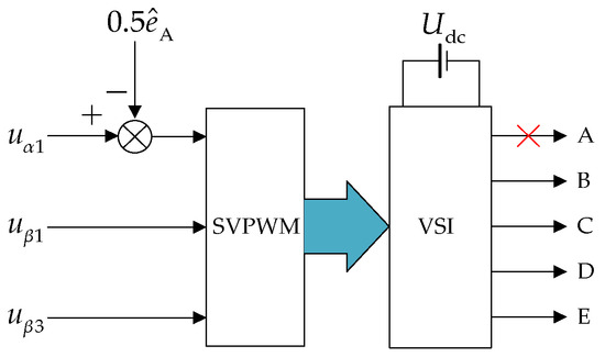
Figure 4.
Control diagram of system under A-phase open circuit with feedforward compensation.
6. Fault-Tolerant Control Strategy under ITSC Fault
6.1. The Principle of Torque Ripple Suppression
The five-phase PMSM adopts dual-closed loop control mode. Because the proportional integral controller can control the DC component without static error, the speed controller and current controller usually use PI controllers. When ITSC fault occurs in one phase winding, the power supply of the faulty phase is stopped. The motor control system should switch to open-circuit mode.
The five-phase PMSM adopts vector control strategy during fault-tolerant control operation. The block diagram of the control system is shown in Figure 5.
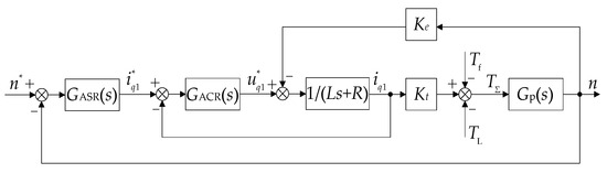
Figure 5.
Speed–current dual-closed loop block diagram considering torque ripple.
In Figure 5, and are the transfer functions of the speed and current controller respectively; and are the torque factor and the electromotive force factor respectively; is the controlled object, where J is the system inertia and B is the friction factor; and n are the reference speed and actual speed respectively; and are the reference current and reference voltage of the q1 axis respectively. The closed loop transfer function of the current loop can be expressed as:
where is the equivalent time constant. Since is related to the system sampling time, inverter switching delay and current filter time constant, the time constant of the current loop is small, so can be considered as 1.
According to the previous analysis, the torque ripple component of the motor includes and :
Speed loop adopts PI controller:
when is simplified as integral part, we can get the transfer function from the torque ripple to the sum of torque :
Substituting into Equation (22), it can be transformed into a frequency characteristic equation. The amplitude-frequency characteristic of can be expressed as:
It can be seen from Equation (23) that determines the system’s ability to suppress torque ripple. For torque ripple at the fixed frequency ω, increase the PI controller proportional coefficient , will become smaller. At this time, the amplitude of becomes smaller, and the torque ripple is suppressed. However, due to the error in the measured value of the speed, when the proportional coefficient of the controller takes a larger value, the given value of the q axis current will bring an error, which will affect the control performance of the system. For torque ripple at the fixed frequency, a controller can be connected in parallel to the speed controller. Let the controller perform proportional gain compensation on the ripple component at the specific frequency, thereby suppressing torque ripple. This paper parallels a repetitive controller.
6.2. The Design of Repetitive Controller
The internal model structure of the RC is shown in Figure 6 [27,28,29,30]. In order to facilitate the design of the RC, the following will be analyzed under the discrete model.
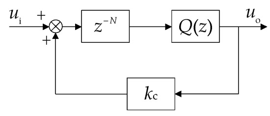
Figure 6.
The structure diagram of the RC.
The transfer function of the controller from input to output is as follows:
where is the delay part; is a constant from 0 to 1; is the transfer function of the low-pass filter.
The value of N in the delay part is determined by the torque ripple frequency. According to the analysis in Section 4 and Section 5, after the ITSC fault occurs in the motor, the electromagnetic torque will appear even-order ripple components of the fundamental frequency . At this time, if N is set to , the controller will generate gain at even-order of , as shown in Figure 7. Here is the system sampling frequency. is determined by the motor speed. When the motor occurs the ITSC fault at different speeds, is different, and the value of N is also different. By changing the value of N in the delay part, fault-tolerant control of the motor at different speeds can be realized. For the constant , when it is set to 1, the ripple component in the controller input can be completely eliminated. However, it can be seen from Figure 7 that the controller has the larger gain at the resonance frequency and its robustness is lower.
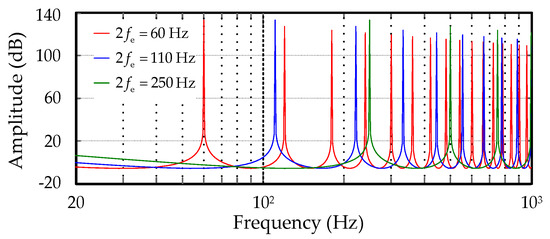
Figure 7.
When and , the amplitude-frequency characteristic curves of RC under different resonance frequencies.
In order to improve robustness, is usually set to a constant less than 1. When and are equal to 0.9, 0.95, 0.98 respectively, the amplitude-frequency characteristic curve of is shown in Figure 8. When the value of is closer to 1, the gain of the controller at the resonance frequency is higher. At this time, the control accuracy of the system will be improved, but the stability will be reduced. In order to reduce the gain of the controller at high frequencies, a low-pass filter is added after the delay part and before the feedback loop. The transfer function of the low-pass filter is as follows:
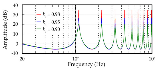
Figure 8.
When , the amplitude-frequency characteristic curves of RC under different .
Due to the symmetry of , its output has no phase shift relative to the input. When and take 0.95, the amplitude-frequency characteristic curve of is shown in Figure 9.
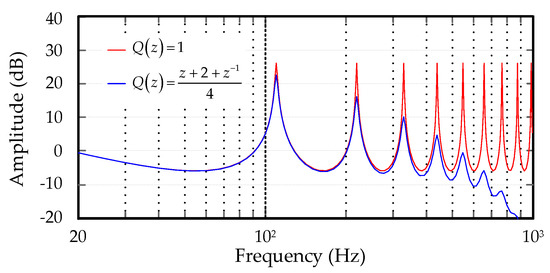
Figure 9.
When , the amplitude-frequency characteristic curves of RC under different .
ITSC faults may occur at any speed. At the same sampling frequency, may appear fractional, which makes the number of samples N in the delay part appear fractional. Usually, the fraction part is ignored, and the sampling number N is taken as the integer part. But ignoring the fraction part will reduce the control effect. By using Lagrange-interpolation, the fractional delay part can be approximated, thereby improving the control effect [31,32]. Let , where I is the integer part, and F is the fraction part in the range of 0 to 1. The fraction delay part can be expressed as Equation (26), and Equation (27) is the Lagrange coefficient. When the order η is larger, the approximation effect is better, but the calculation will increase. Therefore, on the premise of ensuring the control effect, the order should be selected reasonably:
In order to ensure the stability of the RC, it is necessary to add a compensation part in the controller. is the control gain and is the leading compensation. The complete RC structure is shown in the dashed box in Figure 10, and its transfer function is as follows [33]:
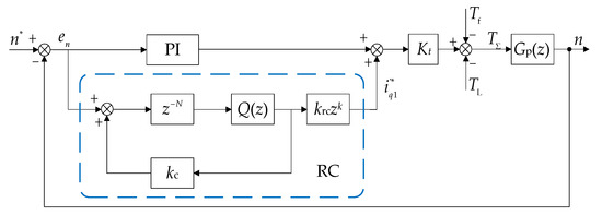
Figure 10.
The block diagram of the control system with RC.
It can be seen from Figure 10 that can be expressed as:
From this equation, the characteristic polynomial of the system can be expressed as:
where is the control object of RC. It is a closed loop transfer function from torque disturbance to speed n when the PI controller acts alone:
It can be seen from Equation (30) that the stability of the system is affected by the PI and RC parameters. The first part in the equation is related to the design of PI parameters, and it should be ensured that its characteristic root is within the unit circle. The second part is related to the design of RC parameters. It should be ensured that its characteristic root is also in the unit circle. Substituting the transfer function of RC into , we can get:
where:
The condition for system stability is that the characteristic root of Equation (32) is in the unit circle. Therefore, if the leading part compensates for the phase offset of , and satisfies , the system will best able [29,33].
Under the single action of torque disturbance , taking as input and as output, Equation (34) can be obtained. Therefore, the amplitude-frequency characteristic curve of when the PI controller acts alone and PI and RC act together can be obtained in Figure 11.
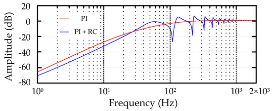
Figure 11.
The amplitude-frequency characteristic curves of .
It can be seen from Figure 11 that when the PI controller acts alone, the system has a poor effect on torque ripple suppression. The torque ripple generated by ITSC fault will cause to produce torque ripple. When the RC is connected in parallel with the PI controller, the ripple component at the frequency in will be suppressed, thereby achieving the torque ripple suppression effect.
7. Simulation Analysis
In order to verify the effect of the RC on the torque ripple suppression, the simulation analysis was carried out by MATLAB.
After an ITSC fault occurs, the power supply of the faulty phase is stopped, and the SVPWM control method under open circuit is adopted. The structure diagram of the control system after ITSC fault is shown in Figure 12, and the parameters of the five-phase PMSM are shown in Table 1.
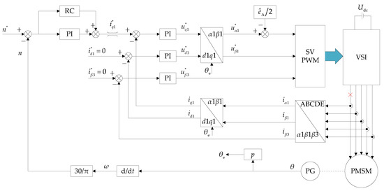
Figure 12.
Fault-tolerant control system of five-phase PMSM under ITSC fault.

Table 1.
Parameters of five-phase PMSM.
Figure 13 shows the torque and speed waveforms of the five-phase PMSM before and after the ITSC fault occurs in the No. 12 coil of the A-phase winding when the speed is 300 r/min and the output torque is 30 Nm. When the motor is running normally, there is no ripple in the output torque. At t1, the No. 12 coil in Figure 2 has the ITSC fault, and the output torque has ripple component of even-order frequency. Stop supplying power to the faulty phase at t2 so that the faulty phase current is zero. By changing the control mode, the system works in the SVPWM control method under open circuit. The torque ripple at this time is produced by Tsf and Tof together. It can be seen from Figure 14a that the peak-to-peak value of torque ripple is 15 Nm. In order to suppress torque ripple, RC is connected in parallel to the PI controller of the speed loop at t3, and the RC is allowed to perform gain compensation for the speed ripple components. It can be seen from Figure 14b that the torque is relatively stable at this time, and the torque ripple has been effectively suppressed. Figure 13b is the speed waveform before and after an ITSC fault of the A-phase winding. The speed ripple is related to the torque ripple. When the former is greater, the speed ripple is also greater.
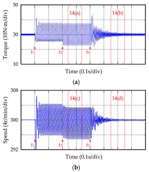
Figure 13.
Torque and speed waveforms of five-phase PMSM before and after ITSC fault: (a) The output torque under normal, short-circuit, and fault-tolerant conditions; (b) The speed under normal, short-circuit, and fault-tolerant conditions.
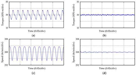
Figure 14.
Amplified waveforms of torque and speed of five-phase PMSM: (a) Torque waveform of removing faulty phase after short-circuit; (b) Torque waveform after adding RC; (c) Speed waveform of removing faulty phase after short-circuit; (d) Speed waveform after adding RC.
When the ITSC fault occurs at t1, the speed will also ripple greatly. After removing the faulty phase winding at t2, it can be seen from Figure 14c that the peak-to-peak value of the speed ripple is 8.5 r/min. After adding the RC controller at t3, it can be seen from Figure 14d that the speed ripple will be effectively suppressed, and the speed waveform is relatively stable. Figure 15a,b are the current waveforms before and after adding RC. After removing the faulty phase of the A-phase, the current waveform is shown in Figure 15a, and the current waveform has large distortion. After adding RC, the current waveform is changed. In Figure 15b, the amplitude of the B-phase and D-phase current has increased, and the additional current component will reduce the torque ripple.
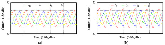
Figure 15.
Current waveform of five-phase PMSM: (a) Current waveform of removing faulty phase after a short-circuit; (b) Current waveform after adding RC.
Figure 16 and Figure 17 show the torque waveforms when the motor works at 600 r/min and 50 r/min, respectively. At different speeds, the fundamental frequency fe is different and the torque ripple frequency is consequently different. By changing the value of N in the delay part, torque ripple can be suppressed. In Figure 16, the motor works at 600 r/min, and the peak-to-peak value of torque ripple is 18 Nm. After adding RC, the motor output torque ripple is suppressed, and the motor torque is relatively stable. In Figure 17, the motor works at 50 r/min, and the peak-to-peak value of torque ripple is 7 Nm. After adding RC, the torque ripple is suppressed, and the output torque waveform has no obvious ripple.
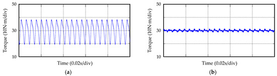
Figure 16.
Torque waveform when the speed of five-phase PMSM is 600 r/min: (a) Torque waveform of removing faulty phase after a short-circuit; (b) Torque waveform after adding RC.
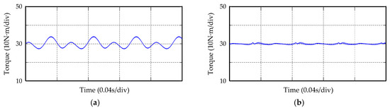
Figure 17.
Torque waveform when the speed of five-phase PMSM is 50 r/min: (a) Torque waveform of removing faulty phase after a short-circuit; (b) Torque waveform after adding RC.
Figure 18 shows the speed waveform of the motor working at different speeds. The existence of torque ripples will cause speed ripples. When the motor works with healthy four-phase windings, and RC is connected in parallel to the speed controller, the speed ripple is suppressed. When the motor speed change, the speed ripple frequency will also change. Now the speed ripple is non-periodic, so RC will output wrong reference current signal. Let the PI controller act alone at this time. When the motor reaches reference speed, add RC again and let RC and PI controller work together. It can be seen from Figure 18 that the speed waveform is relatively stable after adding RC, and there is no obvious ripple component.
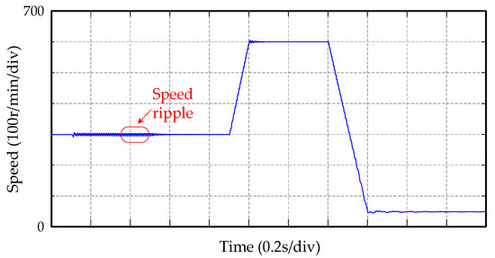
Figure 18.
Speed waveform of five-phase PMSM at different speeds.
Through fast Fourier transforming (FFT), the components of different harmonics in the torque can be obtained in Figure 19. Because the high-order harmonic components in the torque ripple are very small, only the 2nd, 4th, and 6th order frequency components are shown in the figure. The ratios of each harmonic relative to the DC component are shown in Table 2. When the PI controller acts alone, the torque ripple component is larger. When the speed is 50 r/min, the total harmonic distortion (THD) of torque is 10.95%. After adding RC, the THD of torque is 1.29%. When the speed is 300 r/min, the THD of torque is 22.37%. After adding RC, the THD of torque is 2.36%. When the speed is 600 r/min, the THD of torque is 29.09%. After adding RC, the THD of torque is 4.29%.
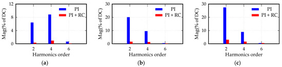
Figure 19.
Harmonic components analysis of torque ripple before and after adding RC: (a) Harmonic components when the speed is 50 r/min; (b) Harmonic components when the speed is 300 r/min; (c) Harmonic components when the speed is 600 r/min.
Table 2.
Harmonic analysis result of the torque.
8. Experimental Analysis
In order to verify the effectiveness of the proposed fault-tolerant control method in five-phase PMSM, the experimental platform with a digital signal processor (DSP) as the core was built. The experimental platform is shown in Figure 20.
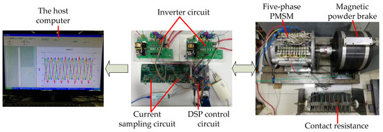
Figure 20.
The experimental platform of five-phase PMSM.
The experimental platform includes the host computer, the control circuits, the inverter circuits, the five-phase PMSM and the magnetic powder brake acting as the load. Among them, DSP model adopts a TMS320F2812 by TI (Dallas, TX, USA). By using a resolver to measure speed and rotor position, the output signal of the resolver is transformed by the decoder chip AD2S1210 (Analog Devices, Norwood, MA, USA) and then transmitted to the DSP. The inverter part uses the intelligent power modules (IPM) (Mitsubishi Electric, Tokyo, Japan), and the PWM generated by the DSP is transmitted to the inverter circuit, and the switching devices in the IPM is driven on and off through the inverter circuit. During the experiment, CAN communication (ZLG, Guangzhou, China) was used to send data from the DSP to the host computer. The data can be used to establish the waveforms.
Take the No. 12 coil of the A-phase winding as an example. When the coil occurs 6-turn ITSC fault, the motor control mode is switched to the fault-tolerant control state. At this time, the motor is in the open circuit operation state, and the motor only runs with healthy four phases. When the motor speed is 300 r/min and the load torque is 30 Nm, the motor output torque waveform is shown in Figure 21. The torque is obtained by calculating the measured current and the permanent magnet flux through the host computer. It can be seen from the waveform that the torque ripple is large before RC is added, and the peak-to-peak value of the torque ripple is 17 Nm. After adding RC, the torque ripple is suppressed. The peak-to-peak value of the motor output torque is 5 Nm. Figure 22 shows the speed waveform. Before adding RC, the torque ripple causes the speed to ripple greatly. The peak-to-peak value of the speed ripple is 7 r/min. After adding RC, the speed ripple is also suppressed. The peak-to-peak value of the speed ripple is 2 r/min.
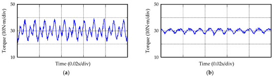
Figure 21.
Torque waveform of five-phase PMSM: (a) Torque waveform of removing faulty phase after a short-circuit; (b) Torque waveform after adding RC.
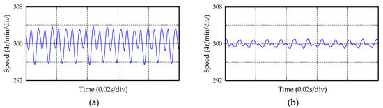
Figure 22.
Speed waveform of five-phase PMSM: (a) Speed waveform of removing faulty phase after a short-circuit; (b) Speed waveform after adding RC.
Figure 23 is the current waveform under the open circuit operation state. After adding RC, the current waveform is changed. The additional current components will offset torque ripple and stabilize the output torque and speed.

Figure 23.
Current waveform of five-phase PMSM: (a) Current waveform of removing faulty phase after a short-circuit; (b) Current waveform after adding RC.
The FFT analysis of the torque is shown in Table 3. When PI controller acts alone, the THD of torque is 22.40%. After adding RC, the THD of torque is 5.19%. It can be seen that RC has the suppression effect on torque ripple under ITSC fault.
Table 3.
Harmonic analysis result of the torque in the experimental part.
9. Conclusions
An ITSC fault is a severe stator winding fault. When the five-phase PMSM is running in open circuit mode due to ITSC fault, short-circuit current and third harmonic flux will cause torque ripple. In this paper, the RC is connected in parallel with the PI controller in the speed loop to suppress torque ripple. The main contributions of this paper are as follows:
- (1)
- After an ITSC fault occurs in the five-phase PMSM, a short-circuit current will appear in the short-circuit coil. Through analysis, the output torque of the motor produces the ripple components at this time. In order to prevent the short-circuit fault from spreading, the power supply to the faulty phase is stopped, and the motor control system turns into open circuit mode. Due to the existence of the third order permanent magnet link, the torque of the healthy four-phase will also contain ripple components. These even-order ripple components make the motor performance worse.
- (2)
- Torque ripples will cause speed ripples. This paper uses RC to perform proportional gain compensation for speed ripple to suppress torque ripple. The design process of the RC is introduced. By connecting RC in parallel with PI controller in the speed loop, the effect of torque ripple suppression can be achieved.
- (3)
- The discrete model of the motor control system is established in the paper. By changing the delay part in the RC, the resonant frequency of the RC is changed, thereby suppressing the torque ripple at different speeds. Simulation and experimental results show that the proposed fault-tolerant control strategy can effectively suppress torque ripple.
The proposed torque ripple suppression method is an appropriate control strategy for five-phase PMSM under ITSC fault, which can improve the fault tolerance of the system. How to quickly and accurately detect the phase where the short-circuit fault is located is significant to fault-tolerant control. The detection of faulty phase in five-phase PMSM can be further studied in future work.
Author Contributions
Conceptualization, D.W. and Y.C.; methodology, D.W.; software, D.W.; validation, D.W. and Y.C.; formal analysis, Y.C. and D.W.; writing—original draft preparation, D.W.; writing—review and editing, Y.C. and D.W. Both authors have read and agreed to the published version of the manuscript.
Funding
This research received no external funding
Acknowledgments
The authors would like to appreciate the reviewers and editor for their critical suggestions, which are very helpful to this paper.
Conflicts of Interest
The authors declare no conflict of interest.
References
- Mohammadpour, A.; Sadeghi, S.; Parsa, L. A generalized fault-tolerant control strategy for five-phase PM motor drives considering star, pentagon and pentacle connection of stator windings. IEEE Trans. Ind. Electron. 2014, 61, 63–75. [Google Scholar] [CrossRef]
- Duran, M.J.; Barrero, F. Recent advances in the design, modeling, and control of multiphase machines-part II. IEEE Trans. Ind. Electron. 2016, 63, 459–468. [Google Scholar] [CrossRef]
- Patel, V.I.; Wang, J.B.; Nugraha, D.T.; Vuletic, R.; Tousen, J. Enhanced availability of drivetrain through novel multiphase permanent-magnet machine drive. IEEE Trans. Ind. Electron. 2016, 63, 469–480. [Google Scholar] [CrossRef]
- Guo, H.; Xu, J.Q.; Chen, Y.H. Robust control of fault-tolerant permanent magnet synchronous motor for aerospace application with guaranteed fault switch process. IEEE Trans. Ind. Electron. 2015, 62, 7309–7321. [Google Scholar] [CrossRef]
- Xue, S.; Wen, X.H.; Wang, Y.L. Multi-dimensional control in multiphase permanent motor drives. Trans. China Electrotech. Soc. 2008, 23, 65–69. [Google Scholar] [CrossRef]
- Ryu, H.M.; Kim, J.H.; Sul, S.K. Analysis of multiphase space vector pulse-width modulation based on multiple d-q spaces concept. IEEE Trans. Power Electron. 2005, 20, 1364–1371. [Google Scholar] [CrossRef]
- Xu, L.; Zhao, W.X.; Liu, G.H. Improved SVPWM fault-tolerant control strategy for five-phase permanent-magnet motor. Energies 2019, 12, 4626. [Google Scholar] [CrossRef]
- Sun, G.D.; Yang, G.J.; Wang, Y.Y.; Su, J.Y. Unified fault-tolerant control strategy with torque ripple compensation for five-phase permanent magnet synchronous motor based on normal decoupling. Energies 2019, 12, 1127. [Google Scholar] [CrossRef]
- Dwari, S.; Parsa, L. Fault-tolerant control of five-phase permanent-magnet motors with trapezoidal back EMF. IEEE Trans. Ind. Electron. 2011, 58, 476–485. [Google Scholar] [CrossRef]
- Wu, F.; Tong, C.D.; Sui, Y.; Cheng, L.M.; Zheng, P. Influence of third harmonic back EMF on modeling and remediation of winding short circuit in a multiphase PM machine with FSCWs. IEEE Trans. Ind. Electron. 2016, 63, 6031–6041. [Google Scholar] [CrossRef]
- Jiang, X.F.; Huang, W.X.; Cao, R.W.; Hao, Z.Y.; Jiang, W. Electric drive system of dual-winding fault-tolerant permanent-magnet motor for aerospace applications. IEEE Trans. Ind. Electron. 2015, 62, 7322–7330. [Google Scholar] [CrossRef]
- Chen, Y.G.; Liu, B. Design and analysis of a five-phase fault-tolerant permanent magnet synchronous motor for aerospace starter-generator system. IEEE Access. 2019, 7, 135040–135049. [Google Scholar] [CrossRef]
- Sen, B.; Wang, J. A fast detection technique for stator inter-turn fault in multi-phase permanent magnet machines using model based approach. In Proceedings of the 7th IET International Conference on Power Electronics, Machines and Drives (PEMD 2014), Manchester, UK, 8–10 April 2014; pp. 1–6. [Google Scholar] [CrossRef]
- Sui, Y.; Yin, Z.S.; Cheng, L.M.; Liu, J.Q.; Zheng, P.; Tang, D.J. Short-circuit fault detection for a five-phase 30-slot/32-pole permanent-magnet synchronous machine. In Proceedings of the 21st International Conference on Electrical Machines and Systems (ICEMS 2018), Jeju, Korea, 7–10 October 2018; pp. 50–54. [Google Scholar] [CrossRef]
- Cui, R.H.; Fan, Y.; Li, C.X. On-line inter-turn short-circuit fault diagnosis and torque ripple minimization control strategy based on OW five-phase BFTHE-IPM. IEEE Trans. Energy Convers. 2018, 33, 2200–2209. [Google Scholar] [CrossRef]
- Zhou, H.W.; Liu, G.H.; Zhao, W.X.; Yu, X.D.; Gao, M.H. Dynamic performance improvement of five-phase permanent-magnet motor with short-circuit fault. IEEE Trans. Ind. Electron. 2018, 65, 145–155. [Google Scholar] [CrossRef]
- Fan, Y.; Cui, R.H.; Zhang, A. Torque ripple minimization for inter-turn short-circuit fault based on open-winding five phase FTFSCW-IPM motor for electric vehicle application. IEEE Trans. Veh. Technol. 2020, 69, 282–292. [Google Scholar] [CrossRef]
- Chen, Y.G.; Zhang, B. Minimization of the electromagnetic torque ripple caused by the coils inter-turn short circuit fault in dual-redundancy permanent magnet synchronous motors. Energies 2017, 10, 1789. [Google Scholar] [CrossRef]
- Jeong, I.; Hyon, B.J.; Nam, K. Dynamic modeling and control for SPMSMs with internal turn short fault. IEEE Trans. Power Electron. 2013, 28, 3495–3508. [Google Scholar] [CrossRef]
- Baudart, F.; Dehez, B.; Matagne, E.; Telteu-Nedelcu, D.; Alexandre, P.; Labrique, F. Torque control strategy of polyphase permanent-magnet synchronous machines with minimal controller reconfiguration under open circuit fault of one phase. IEEE Trans. Ind. Electron. 2012, 59, 2632–2644. [Google Scholar] [CrossRef]
- Guzman, H.; Duran, M.J.; Barrero, F.; Bogado, B.; Toral, S. Speed control of five-phase induction motors with integrated open-phase fault operation using model-based predictive current control techniques. IEEE Trans. Ind. Electron. 2014, 61, 4474–4484. [Google Scholar] [CrossRef]
- Ullah, Z.; Hur, J. Analysis of inter-turn-short fault in an FSCW IPM type brushless motor considering effect of control drive. IEEE Trans. Ind. Appl. 2020, 56, 1356–1367. [Google Scholar] [CrossRef]
- Tian, B.; An, Q.T.; Duan, J.D.; Sun, D.Y.; Sun, L.; Semenov, D. Decoupled modeling and nonlinear speed control for five-phase PM motor under single-phase open fault. IEEE Trans. Power Electron. 2017, 32, 5473–5486. [Google Scholar] [CrossRef]
- Tian, B.; Mirzaeva, G.; An, Q.T.; Sun, L.; Semenov, D. Fault-tolerant control of a five-phase permanent magnet synchronous motor for industry applications. IEEE Trans. Ind. Appl. 2018, 54, 3943–3952. [Google Scholar] [CrossRef]
- Xiong, C.; Xu, H.P.; Zhou, P.; Guan, T. Fault-tolerant field oriented control for five-phase permanent-magnet motors under single phase open fault. Proc. Chin. Soc. Elect. Eng. 2019, 39, 7055–7064. [Google Scholar] [CrossRef]
- Chen, Y.G.; Bao, Z.M.; Lin, C.H.; Zhao, X.B. Fault-tolerant SVPWM control strategy for five-phase PMSM under single-phase open-circuit fault. In Proceedings of the 10th International Conference on Applied Energy (ICAE2018), Hong Kong, China, 22–25 August 2018; pp. 2605–2610. [Google Scholar] [CrossRef]
- Song, J.C.; Wang, X.; Lin, L.Y.; Gao, Y.G.; Lu, S.X.; Sun, T. Study of fast repetitive control strategy based on transformerless hybrid active power filter. High Voltage Eng. 2019, 45, 2037–2045. [Google Scholar] [CrossRef]
- Schulting, P.; van der Broeck, C.H.; Doncker, R. Analysis and design of repetitive controllers for applications in distorted distribution grids. IEEE Trans. Power Electron. 2019, 34, 996–1004. [Google Scholar] [CrossRef]
- Herran, M.A.; Fischer, J.R.; Gonzalez, S.A.; Judewicz, M.G.; Carugati, I.; Carrica, D.O. Repetitive control with adaptive sampling frequency for wind power generation systems. IEEE J. Emerg. Sel. Top. Power Electron. 2014, 2, 58–69. [Google Scholar] [CrossRef]
- Bing, Y.Q.; Jiang, D.Z.; Liang, Y.Q.; Jiang, C.X.; He, T.X.; Yang, L.; Hu, P.F. Modified modeling and system stabilization of shunt active power filter compensating loads with µf capacitance. Energies 2019, 12, 2084. [Google Scholar] [CrossRef]
- Cui, P.; Wang, Q.R.; Zhang, G.X.; Gao, Q. Hybrid fractional repetitive control for magnetically suspended rotor systems. IEEE Trans. Ind. Electron. 2018, 65, 3491–3498. [Google Scholar] [CrossRef]
- Wu, Y.L.; Li, H.; Song, X.D.; Chen, B.D. Suppression of harmonic current in permanent magnet synchronous motors using improved repetitive controller. Trans. China Electrotech. Soc. 2019, 34, 2277–2286. [Google Scholar] [CrossRef]
- Kolluri, S.; Gorla, N.B.Y.; Sapkota, R.; Panda, S.K. A new control architecture with spatial comb filter and spatial repetitive controller for circulating current harmonics elimination in a droop-regulated modular multilevel converter for wind farm application. IEEE Trans. Power Electron. 2019, 34, 10509–10523. [Google Scholar] [CrossRef]


Publisher’s Note: MDPI stays neutral with regard to jurisdictional claims in published maps and institutional affiliations. |
© 2020 by the authors. Licensee MDPI, Basel, Switzerland. This article is an open access article distributed under the terms and conditions of the Creative Commons Attribution (CC BY) license (http://creativecommons.org/licenses/by/4.0/).