Article

Adaptive Higher-Order Sliding Mode Control of Series-Compensated DFIG-Based Wind Farm for Sub-Synchronous Control Interaction Mitigation

School of Information Science and Electrical Engineering, Shandong Jiaotong University, Jinan 250357, China
*
Author to whom correspondence should be addressed.
Energies 2020, 13(20), 5421; https://doi.org/10.3390/en13205421
Submission received: 19 August 2020 / Revised: 5 October 2020 / Accepted: 13 October 2020 / Published: 16 October 2020
(This article belongs to the Special Issue Optimal Control and Nonlinear Dynamics in Electrical Power Systems)

Abstract

:
Sub-synchronous control interaction (SSCI) is an oscillation phenomenon caused by the interaction of converter control and series-compensated transmission line. This paper proposes a novel adaptive higher-order sliding mode (AHOSM) control strategy for damping the SSCI of a series-compensated DFIG-based wind power system. On the basis of system modeling and oscillation mechanism analysis, SSCI suppression is converted to the current tracking control problem. Firstly, an auxiliary feedback control is employed for the nonlinear series-compensated system, then integral sliding mode functions are defined to design a second-order sliding mode control law for the equivalent system. Adaptive laws for the control gains are then conceived based on the Lyapunov function considering unknown upper bounds of uncertainty derivatives. System stability is also analyzed in detail along with adaptive laws’ design. The effectiveness of the proposed control scheme is verified under different series-compensated level, different wind speed, symmetric and asymmetric short circuit fault, and internal and external disturbances. The PI control and conventional first-order sliding mode control scheme are also executed to compare the damping effect.

1. Introduction

As a clean and renewable energy, wind energy has been widely used along with increasingly serious energy crisis and environmental pollution [1]. Among the existing wind-power generation systems, DFIG-based wind-power system, with the advantages of a wide speed range, high wind-energy utilization efficiency, variable speed and constant frequency operation, and independent control of active and reactive power, has dominated the wind-power market [2]. However, wind farms tend to be located in remote areas or offshore, far from load centers [3]. This is needed to improve the capacity of power transmission lines, yet it is expensive to enhance the transmission capacity through the expansion of power infrastructure [4].
A cost-effective way to enhance the transmission capacity of power lines is to apply series-compensated capacitors. However, this will cause sub-synchronous oscillation if the series-compensated level is too high. According to different interaction objects, the oscillation can be divided into three types: sub-synchronous resonance (SSR), sub-synchronous torsional interactions (SSTI) and sub-synchronous control interaction (SSCI) [5]. Considering the economy and reliability of transmission lines, series-compensated level in practice is generally less than 70%, and the self-excitation condition of electrical resonance is difficult to satisfy. Thus, SSR is not the main type of sub-synchronous oscillation of wind turbines under normal conditions. The studies of SSTI are mainly focused on thermal power units, which have not been encountered in actual wind-power projects [6]. In fact, SSCI is the most noteworthy for the wind power system. SSCI is a kind of sub-synchronous oscillation caused by the interaction between the wind turbine controller and weak AC system or series-compensated line. It does not involve the oscillation of a mechanical shaft such that the oscillation divergence speed is fast. It may lead to a wind turbine being off-grid and irreversible damage to electronic equipment in serious cases, which will affect the safe and stable operation of DFIG-based wind power system [7]. Similar failures have been reported in America and China [8]. Thus, SSCI has attracted the attention of many scholars.
The mechanism of SSCI has been deeply analyzed in the literature [9]. In recent years, scholars have also been exploring the damping methods. Supplementary SSCI damping schemes are designed in [10,11,12], yet the controllers act on the grid-side converter (GSC) control loop, which limits the damping effect. In [13], a damping controller is simultaneously added into the dq-axis control channels in the inner current loop of the rotor-side converter (RSC), and a particle swarm optimization algorithm is applied to achieve the optimum control gains, which helps to maximize the mitigation effect under different series-compensated levels and wind speeds. A supplementary linear-quadratic regulator is applied to the inner current control loops of RSC in [14]. These controllers [13,14] are both attached to the RSC controllers, which inevitably involve the coordination problem among different controllers. This can increase the control complexity and may affect the system stability. Without adding supplementary damping controllers, the authors of [15] proposed a new method to mitigate SSCI based on the phase-shift average of the rotor current. Paper [16] discussed a non-dominated sorting genetic algorithm to optimize the PI control parameters of converters to improve system damping.
The control methods discussed above, whether supplementary damping control or improved original converter controllers, are all based on the linearized model. However, the series-compensated DFIG-based wind power system is essentially nonlinear. The control performance of these linear model controllers may be deteriorated when the operating points are changed. Based on the partial feedback linearization method, damping controllers are designed for GSC and RSC respectively in [17,18]. Paper [19] continued this study and simultaneously applied partial feedback linearization control for both GSC and RSC, and the damping effect for SSCI is further improved.
However, the partial feedback linearization method is not robust to both external and internal uncertainties. There are internal parameter perturbations and various external disturbances in the practical series-compensated system, such that the robustness is particularly important. Aiming at a multi-input, multi-output, uncertain state-space model of a series-compensation wind farm, an H damping controller for inner current loop of RSC is presented in [20]. An active disturbance rejection controller is added to the current inner loop of RSC to compensate for uncertainties in [21].
Another robust control method which is widely used in power systems is sliding mode control. System states possess the advantage of invariance to matched uncertainty when they are on a sliding mode hyperplane [22,23]. Sliding mode control has been used in DIFG [24,25,26], and a conventional first-order sliding mode is also adopted in SSCI suppression control. In [27,28], SSCI mitigation was studied by combining partial feedback linearization with a first-order sliding mode. Paper [29] also proposed a rotor current regulator based on the first-order sliding mode, which can suppress SSCI by controlling the dynamic of rotor current. However, these studies [27,28,29] are all based on the conventional first-order sliding mode, and the suppression of sliding mode chattering is less considered. This chattering will also increase rotor voltage oscillation, and then affect the rotor current. Moreover, it is difficult to determine the upper bounds of the uncertainties existing in the series-compensated system, whereas all these methods require that the upper bounds of the uncertainties can be known in advance.
The higher-order sliding mode control has higher accuracy and smaller chattering than the first-order sliding mode by hiding discontinuous sign-function in a high-order time derivative of the sliding variable [30,31]. As a member of the higher-order sliding mode, the second-order sliding mode super-twisting algorithm is widely applied in the electromechanical control field [32,33]. Consequently, considering the uncertain nonlinear characteristics, unknown upper bound of uncertainty derivative, sliding mode chattering problem and the requirement for system robustness, this paper proposes an adaptive higher-order sliding mode (AHOSM) control strategy for a series-compensated DFIG-based wind power system. Rotor current control laws are designed by combining feedback control and second-order sliding mode super-twisting algorithm. Adaptive control gains are constructed based on the Lyapunov method to remove the constraint for the upper bound of uncertainty. The dual objectives of SSCI mitigation and power regulation are both deliberately considered. The performance of the proposed control scheme is evaluated via the MATLAB/Simulink platform.
The rest of the paper is organized as follows: Section 2 discusses a series-compensated DFIG-based wind power system model and SSCI analysis. A detailed AHOSM control scheme for SSCI mitigation is presented in Section 3. Simulations under different operating conditions are discussed in Section 4. Section 5 draws conclusions.

2. System Modeling and SSCI Analysis

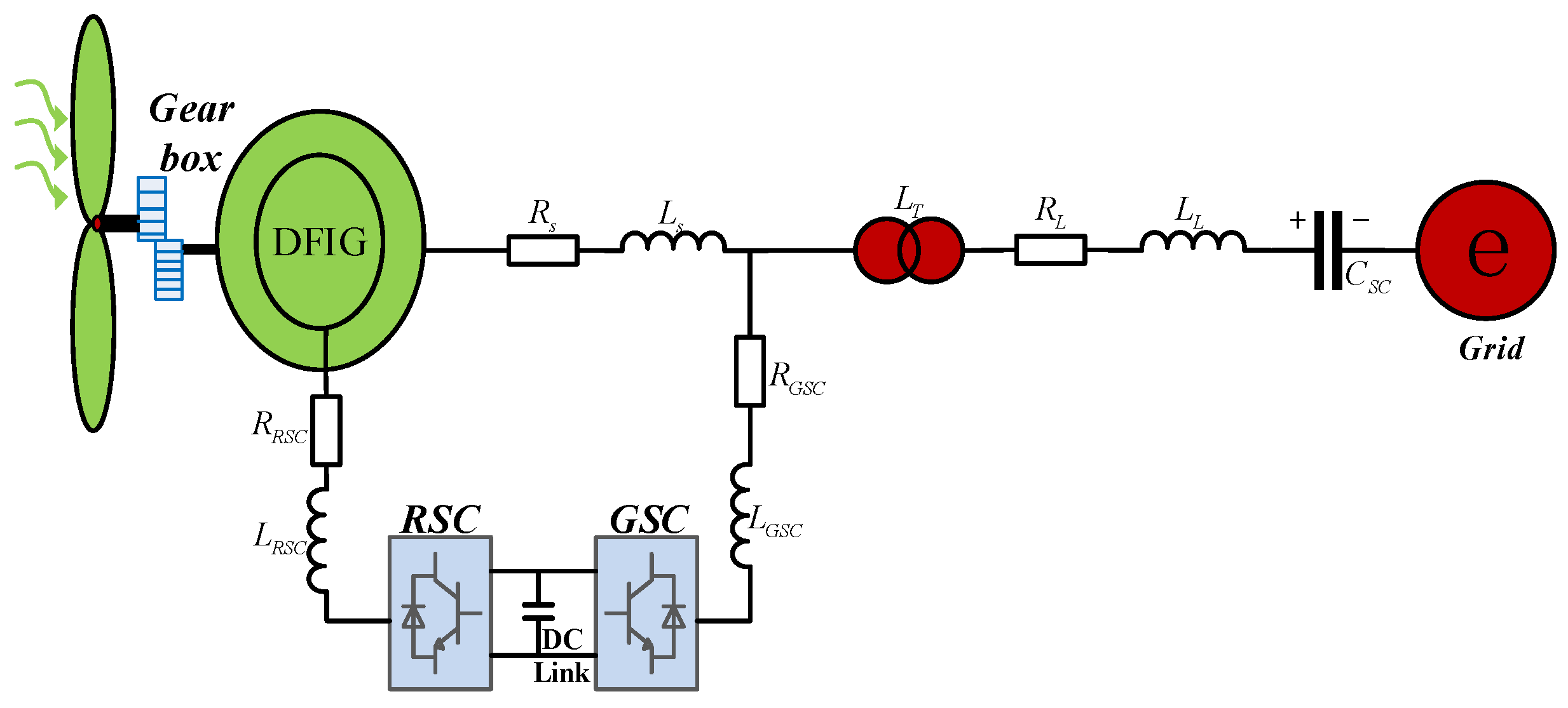
2.1. Series-Compensated DFIG-Based Wind Farm Grid-Connected System Modeling
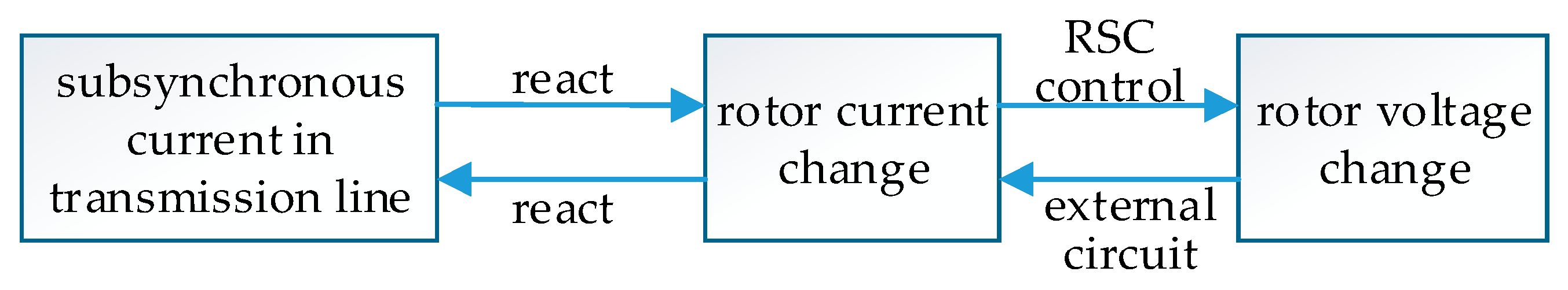
The schematic of a series-compensated DFIG-based wind farm grid-connected system is shown in Figure 1. A 100 MW wind farm is composed of 50 DFIGs (2 MW per unit). It has been proved that the aggregated DFIG of a wind farm can be adopted in sub-synchronous oscillation study [5,10]. The equivalent DFIG is connected to an infinite grid through a transformer and series-compensated transmission line. DFIG stator is directly connected to grid and the rotor is connected through back-to-back converter. The system consists of a wind turbine, shafting, DFIG, RSC, GSC and series-compensated transmission line. In Figure 1, R R S C , L R S C , R G S C , L G S C are the link resistances and inductances of RSC and GSC. R s , L s are stator resistance and inductance. L T represents the equivalent inductance of the step-up transformer. R L , L L are the resistance and inductance of the series-compensated transmission line. The series-compensated capacitor is denoted as C S C .
Wind turbine can convert wind energy into mechanical energy, and operate under different regions along with different wind speeds. According to aerodynamics theory, the captured mechanical power can be expressed as [17]:
P t = 1 2 ρ π R 2 v 3 C p ( λ t , β t )
where ρ is air density, R is blade radius of wind turbine, v is wind speed, C p ( λ t , β t ) is power coefficient and represents the transfer capacity of the wind turbine from wind energy to mechanical energy. In practice, C p ( λ t , β t ) is normally chosen from 0.25 to 0.45, and can be adjusted via tip speed ratio λ t and pitch angle β t to maximize wind energy efficiency. For a certain wind turbine, C p ( λ t , β t ) can be represented as:
{ C p ( λ t , β t ) = 0.5176 ( 116 λ i 0.4 β t 5 ) e 21 / λ i + 0.0068 λ t 1 λ i = 1 λ t + 0.08 β t 0.035 β t 3 + 1
λ t = R ω t v
where ω t is wind turbine angular speed. Pitch angle β t is set as 0 to achieve maximum power point tracking (MPPT) under the optimal tip speed ratio λ t o p t when wind speed is lower than the rated value, whereas β t should be adjusted to output rated power when wind speed is above the rated speed.
The main function of shafting is to transfer mechanical energy to a generator for electric energy conversion. According to different modeling methods, the shafting model includes a one-mass model, two-mass model and three-mass model. The two-mass model is enough for studying sub-synchronous oscillation. Wind turbine and low-speed shaft are equivalent to a mass, and gear box and high-speed shaft form another mass, then the dynamic equation of the two-mass model is:
{ ω ˙ t = 1 2 H t ( T t K s θ s D t ω t ) ω ˙ r = 1 2 H g ( K s θ s T e D g ω r ) θ ˙ s = 2 π f 1 ( ω t ω r )
where H t , H g are inertia time constants, T t is mechanical torque of wind turbine, K s is the stiffness coefficient of shafting, ω r is angular speed of DFIG rotor, θ s is angular displacement between wind turbine and DFIG rotor, D t , D g are damping coefficients, f 1 is grid frequency.
DFIG dynamics can be represented by stator current and rotor current under dq two-phase synchronous rotating coordinate frame [20,29]:
{ i ˙ r d = L m L o ( u s d + R s i s d L s i s q ω r ) L s L o R r r i r d + i r q ω 1 L r r L s L o i r q ω r + L s L o u r d i ˙ r q = L m L o ( u s q + R s i s q + L s i s d ω r ) L s L o R r r i r q i r d ω 1 + L r r L s L o i r d ω r + L s L o u r q i ˙ s d = L m L o ( i r d R r r + L r r i r q ω r ) + L r r L o u s d L r r L o R s i s d + i s q ω 1 + L m 2 L o i s q ω r L m L o u r d i ˙ s q = L m L o ( i r q R r r L r r i r d ω r ) + L r r L o u s q L r r L o R s i s q i s d ω 1 L m 2 L o i s d ω r L m L o u r q
where, R r r = R r + R R S C , L r r = L r + L R S C , i s d , i s q , i r d , i r q , u s d , u s q , u r d , u r q are currents and voltages of stator and rotor, L s , L r , L m are stator inductance, rotor inductance and mutual inductance, L o = 1 L r r L s L m 2 , ω 1 is grid angular frequency.
GSC is a factually voltage type PWM rectifier which is relatively independent with RSC. Wind speed variation can lead to slip power fluctuation, and then the exciting power will also fluctuate accordingly. Thus, RSC can be regarded as a nonlinear load for GSC. The DC link voltage will produce a ripple when this load is changed. Therefore, GSC control is a key part of the whole control system to maintain DC link voltage. GSC and DC link dynamics can be described as:
{ i ˙ g d = ω 1 i g q R G S C L G S C i g d u s d L G S C + u g d L G S C i ˙ g q = ω 1 i g d R G S C L G S C i g q u s q L G S C + u g q L G S C
u ˙ d c = 1 C d c ( i d c G S C i d c R S C )
where u g d , u g q , i g d , i g q are voltages and currents of GSC loop, u d c , C d c are DC link voltage and capacitor, and i d c G S C , i d c R S C are currents flowing through both sides of the capacitor.
The series-compensated transmission line is mainly composed of the transformer, electric transmission line, series-compensated capacitor and infinite grid. The internal resistance of the transformer and electric transmission line can be equivalent to the RL line if neglecting the influence of transformer saturation and distributed capacitance. Then, the dynamic equations of series-compensated transmission line under the dq reference frame are:
{ i ˙ l d = R L L L i l d + ω 1 i l q + 1 L L ( V t d u s c d E d ) i ˙ l q = R L L L i l q ω 1 i l d + 1 L L ( V t q u s c q E q ) u ˙ s c d = ω 1 u s c q + 1 C S C i l d u ˙ s c q = ω 1 u s c d + 1 C S C i l q
where, i l d , i l q are line currents, u s c d , u s c q are the voltage of the series-compensated capacitor, V t d , V t q are the high-voltage side voltages of the transformer. E d , E q are grid voltages.
As above, Formulas (4) to (8) form the mathematical model of the series-compensated, DFIG-based wind power system. The dual control objectives are power regulation and SSCI mitigation. SSCI mechanism analysis will then be carried out for conceiving the control scheme.

2.2. SSCI Analysis

When sub-synchronous disturbance current (with resonant angular frequency ω e r ) appears in the series-compensated transmission line, it will flow into DFIG’s stator winding. Sub-synchronous current of stator winding and transmission line is the same when neglecting the influence of GSC. It is supposed that the sub-synchronous disturbance current is symmetric, then the three-phase stator current of DFIG can be represented as:
{ i s a = 2 I s sin ( ω 1 t + ϕ i s ) + 2 I e r sin ( ω e r t + ϕ i e r ) i s b = 2 I s sin ( ω 1 t + ϕ i s 2 π / 3 ) + 2 I e r sin ( ω e r t + ϕ i e r 2 π / 3 ) i s c = 2 I s sin ( ω 1 t + ϕ i s + 2 π / 3 ) + 2 I e r sin ( ω e r t + ϕ i e r + 2 π / 3 )
where I s , I e r , ϕ i s , ϕ i e r are the effective value and initial phase of stator fundamental current and sub-synchronous current, ω 1 = 2 π f 1 , ω e r = 2 π f e r are synchronous and sub-synchronous angular frequency.
Under dq reference frame, Formula (9) is transferred into:
{ i s d = 2 I s sin ( ϕ i θ s ϕ i s ) 2 I e r sin ( ( ω 1 ω e r ) t + ϕ i θ s ϕ i e r ) = i s d 0 + i s d s u b i s q = 2 I s cos ( ϕ i θ s ϕ i s ) 2 I e r cos ( ( ω 1 ω e r ) t + ϕ i θ s ϕ i e r ) = i s q 0 + i s q s u b
where ϕ i θ s is the initial angle between the stator current axis a and axis d, i s d 0 , i s q 0 , i s d s u b , i s d s u b are the direct components and sub-synchronous components under dq frame.
The stator sub-synchronous current can induce a current in rotor winding with angular frequency ω e r ω r , that is:
{ i r d = 2 I r sin ( ϕ i θ r ϕ i r ) 2 I n sin ( ( ω 1 ω e r ) t + ϕ i θ r ϕ i n ) = i r d 0 + i r d s u b i r q = 2 I r cos ( ϕ i θ r ϕ i r ) 2 I n cos ( ( ω 1 ω e r ) t + ϕ i θ r ϕ i n ) = i r q 0 + i r q s u b
where I r , I n , ϕ i r , ϕ i n are the effective value and initial phase of rotor fundamental current and sub-synchronous current, ϕ i θ r is the initial angle between the rotor current axis a and axis d, i r d 0 , i r q 0 , i r d s u b , i r q s u b are the direct components and sub-synchronous components under the dq frame.
The rotor voltage will be changed and contain sub-synchronous component when sub-synchronous current (angular frequency ω e r ω r ) appeared in rotor winding. The sub-synchronous component of rotor voltage reacts upon rotor winding and induces the change in rotor current, and then causes variations in stator current. The new induced sub-synchronous current will excite the original one reciprocally, which will result in sub-synchronous oscillation.
It can be seen that SSCI can be effectively suppressed as long as the rotor current is controlled to follow the prescribed values. The schematic diagram of the generation process of SSCI is shown as Figure 2.

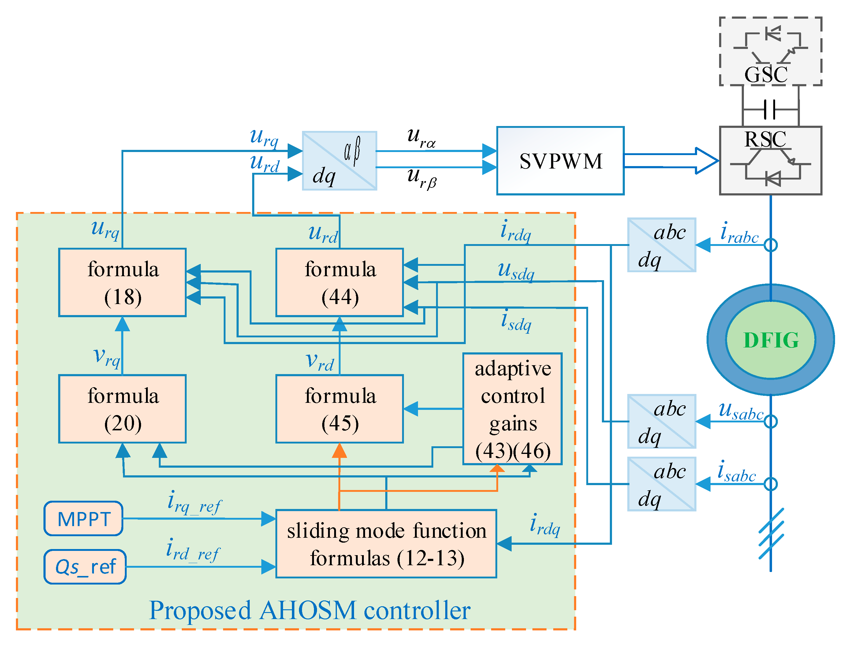
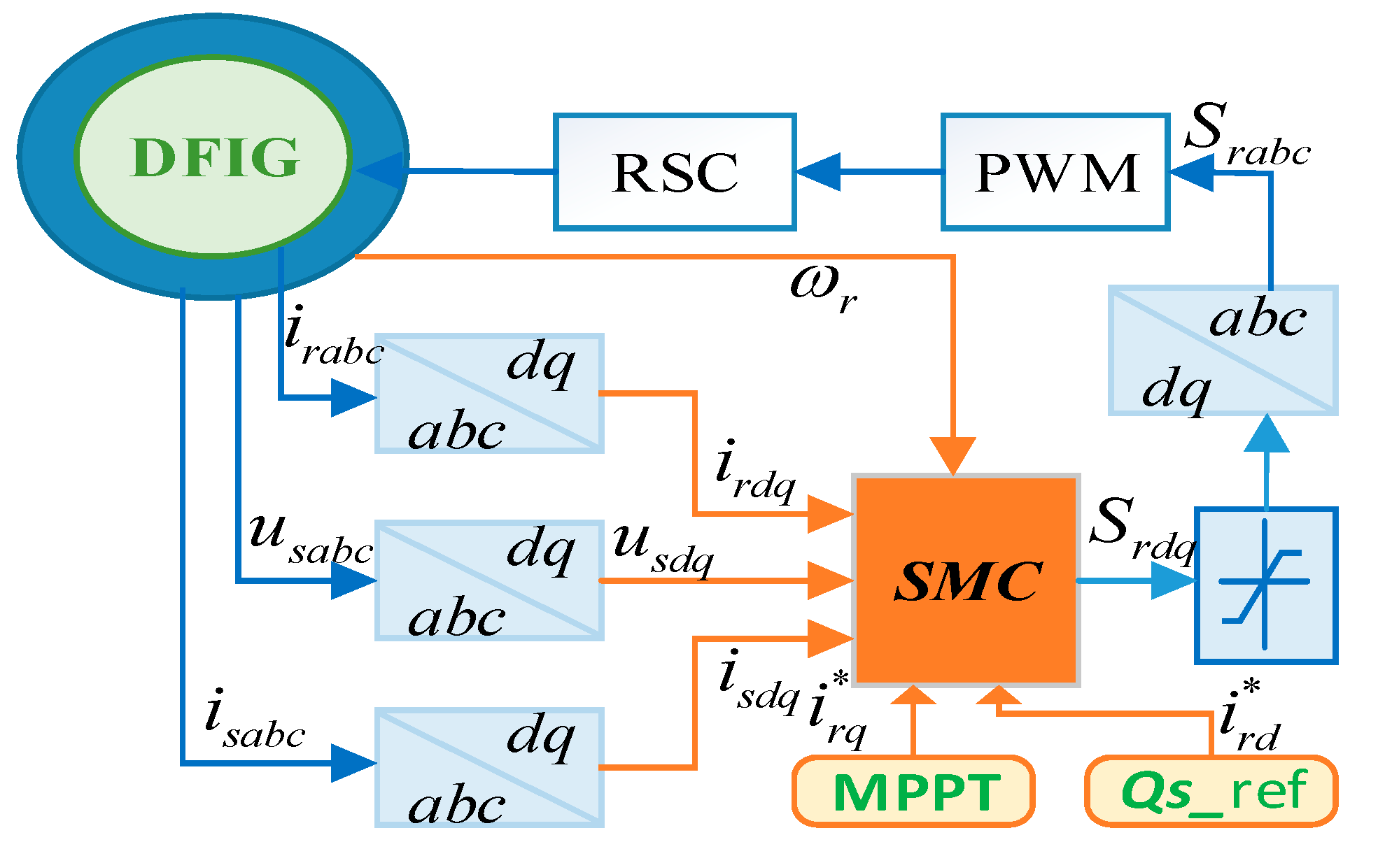
3. AHOSM Control Design

The state equations of series-compensated DFIG-based wind power system are shown in Formulas (4) to (8). State variables are x = [ i r d   i r q   u d c   i s d   i s q     i g d   i g q   i L d   i L q   u s c d   u s c q   ω T   ω r   θ s ] T , control variables are u = [ S r d   S r q ] T , and output equations are chosen as y = [ i r d i r d *   i r q i r q * ] T . The control objectives are power regulation and SSCI mitigation under the unknown upper bounds of the uncertainty derivative. Detailed design processes of AHOSM control laws are presented in this section.
Define sliding mode functions as:
s i r q = ( i r q i r q * ) + c i r q ( i r q i r q * ) d t
s i r d = ( i r d i r d * ) + c i r d ( i r d i r d * ) d t
where i r q * , i r d * are reference values of the rotor current in dq frame, and c i r q , c i r d are positive weight coefficients of integral sliding mode surfaces.
The power control for DFIG is under the stator flux-oriented method, then the stator active power and reactive power can be respectively represented as:
{ P s = 3 L m 2 L s U s i r q Q s = 3 U s 2 L s ω 1 ( U s ω 1 L m i r d )
Then, i r q * , i r d * can be calculated as:
{ i r q = 2 L s P s 3 L m U s i r d = U s ω 1 L m 2 L s Q s 3 L m U s
Here, P s can be inferred via MPPT, and Q s is obtained according to grid demand.
To calculate the time derivatives of sliding mode variables
s ˙ i r q = ( i ˙ r q i ˙ r q * ) + c i r q ( i r q i r q * ) = L m L o ( u s q + R s i s q + L s i s d ω r ) + ( c i r q L s L o R r r ) i r q i r d ω 1 + L r r L s L o i r d ω r i ˙ r q * c i r q i r q * f r q + L s L o g r q u r q + d r q
s ˙ i r d = ( i ˙ r d i ˙ r d * ) + c i r d ( i r d i r d * ) = L m L o ( u s d + R s i s d L s i s q ω r ) + ( c i r d L s L o R r r ) i r d + i r q ω 1 L r r L s L o i r q ω r i ˙ r d * c i r d i r d * f r d + L s L o g r d u r d + d r d
where d r q , d r d are uncertainties including parameter perturbation and external disturbance. d r q and d r d satisfy | d ˙ r q | D r q , | d ˙ r d | D r d . D r q and D r d are unknown.
Once sliding mode functions are defined, then the sliding mode control law can be constructed. The design procedure and stability proof for (16) is presented here in detail, and it is similar for s i r d .
To carry out auxiliary control v r q :
u r q = g r q 1 ( v r q f r q )
Then
s ˙ i r q = v r q + d r q
For Formula (19), control law v r q can be designed by the second-order sliding mode super-twisting algorithm [30]:
{ v r q = α r q | s i r q | s i g n ( s i r q ) + σ r q σ ˙ r q = β r q s i g n ( s i r q )
where α r q , β r q are control gains.
When D r q is known in advance, the control parameters can be chosen as α r q = 1.5 D r q , β r q = 1.1 D r q to guarantee finite time stabilization and establishment of second-order sliding mode with respect to s i r q [22,24]. However, the uncertainty derivative in the series-compensated, DFIG-based system is hard know beforehand. Thus, the adaptive control gains should be conceived. The construction of adaptive control gains and stability proof are presented next in detail.
Define variable s 2 , then Formula (19) is converted as:
{ s ˙ i r q = α r q | s i r q | s i g n ( s i r q ) + s 2 s ˙ 2 = β r q s i g n ( s i r q ) + d ˙ r q
To choose vector ξ T = [ | s i r q | s i g n ( s i r q ) , s 2 ] , and according to d | s i r q | d t = s ˙ i r q s i g n ( s i r q ) , then:
ξ ˙ 1 = 1 2 | s i r q | ( α r q | s i r q | s i g n ( s i r q ) + s 2 )
ξ ˙ 2 = β r q s i g n ( s i r q ) + d ˙ r q
Define d ˙ ˜ r q = | s i r q | d ˙ r q , A = [ α r q 2 1 2 β r q 0 ] , B = [ 0 1 ] T , C = [ 1 0 ] , and combine Formulas (22) and (23), then:
ξ ˙   = 1 | s i r q | ( A ξ + B d ˙ ˜ r q )
Considering Lyapunov function:
V ( ξ , α r q , β r q ) = V 0 ( ξ ) + 1 2 k q 1 ( α r q α r q * ) 2 + 1 2 k q 2 ( β r q β r q * ) 2
where α r q * , β r q * are positive constants, V 0 ( ξ ) = ξ T P ξ , P = [ μ q 2 + 4 η q 2 μ q 2 μ q 2 1 ] , k q 1 , k q 2 , μ q , η q are positive constants. It is noticed that P is positive definite matrix. Then:
V ˙ 0 ( ξ ) = 2 ξ ˙ T P ξ = 1 | s i r q | ( 2 ξ T A T + 2 d ˙ ˜ r q B T ) P ξ 1 | s i r q | ( 2 ξ T A T P ξ + 2 d ˙ ˜ r q B T P ξ + D r q 2 | | s i r q | | d ˙ ˜ r q 2 = 1 | s i r q | ( 2 ξ T A T P ξ + 2 d ˙ ˜ r q B T P ξ + D r q 2 ξ T C T C ξ d ˙ ˜ r q 2 ) 1 | s i r q | ( 2 ξ T A T P ξ + D r q 2 ξ T C T C ξ + ξ T P B B T P ξ ) = 1 | s i r q | ξ T ( A T P + P A + D r q 2 C T C + P B B T P ) ξ
Define Q = ( A T P + P A + D r q 2 C T C + P B B T P ) , then Formula (26) is rewritten as:
V ˙ 0 ( ξ ) 1 | s i r q | ξ T Q ξ
Substituting A, B, C and P into Formula (27), we get:
Q = [ 2 α r q η q + α r q μ q 2 2 β r q μ q μ q 2 4 D r q 2 η q μ q 2 4 α r q μ q 4 + β r q + μ q 2 η q μ q 2 4 α r q μ q 4 + β r q + μ q 2 μ q 2 1 ]
For guaranteeing a positive definite of P , to define:
β r q = η q + μ q 2 4 + μ q α r q 4
Substituting Formula (29) into Formula (28):
Q 1 4 μ q I [ 2 α r q η q + α r q μ q 2 2 β r q μ q μ q 3 4 D r q 2 μ q 2 4 μ q 4 μ q 2 μ q 2 μ q 4 1 ]
According to schur complement theorem, the conditions that Q is the positive definite and the minimum eigenvalue λ min > 1 4 μ q satisfy:
{ α r q > μ q 2 4 + ( α r q η q + μ q 3 4 + D r q 2 + μ q 2 4 + μ q 4 ) ( μ q 4 1 ) ( 2 η q + μ q 2 4 ) ( μ q 4 1 ) μ q > 4
From Formula (27):
V ˙ 0 ( ξ ) 1 | s i r q | ξ T Q ξ μ q 4 | ξ 1 | ξ T ξ = μ q 4 | ξ 1 | ξ 2 = μ q ξ 4 | ξ 1 | ξ
According to ξ 2 2 = ξ 1 2 + ξ 2 2 = | s i r q | + ξ 2 2
ξ 2 | ξ 1 |
Then, Equation (32) can be rewritten as:
V ˙ 0 ( ξ ) μ q 4 ξ 2
According to positive definite quadratic function V 0 ( ξ ) = ξ T P ξ :
λ m i n ( P ) ξ 2 2 V 0 ( ξ ) = ξ T P ξ λ m a x ( P ) ξ 2 2
( V 0 ( ξ ) λ m a x ( P ) ) 1 2 ξ 2
From Formulas (35) and (36),
V ˙ 0 ( ξ ) - r q V 0 1 2 ( ξ )
where r q = μ q 4 λ m a x 1 2 ( P ) . To deduce the time derivative of V ( ξ , α r q , β r q ) :
V ˙ ( ξ , α r q , β r q ) = r q V 0 1 2 ( ξ ) + 1 k q 1 ( α r q α r q * ) α ˙ r q + 1 k q 2 ( β r q β r q * ) β ˙ r q = r q V 0 1 2 ( ξ ) τ q 1 2 k q 1 | α r q α r q * | τ q 2 2 k q 2 | β r q β r q * | + 1 k q 1 ( α r q α r q * ) α ˙ r q + 1 k q 2 ( β r q β r q * ) β ˙ r q + τ q 1 2 k q 1 | α r q α r q * | + τ q 2 2 k q 2 | β r q β r q * | min ( r q , τ q 1 , τ q 2 ) ( V 0 ( ξ ) + 1 2 k q 1 ( α r q α r q * ) 2 + 1 2 k q 2 ( β r q β r q * ) 2 ) 1 2 + 1 k q 1 ( α r q α r q * ) α ˙ r q + 1 k q 2 ( β r q β r q * ) β ˙ r q + τ q 1 2 k q 1 | α r q α r q * | + τ q 2 2 k q 2 | β r q β r q * |
It is supposed that α r q β r q are bounded. Then, there exist α r q * β r q * , satisfying α r q α r q * < 0 , β r q β r q * < 0 . Formula (38) can be written as
V ˙ ( ξ , α r q , β r q ) min ( r q , τ q 1 , τ q 2 ) V 1 2 + ζ
where ζ = | α r q α r q * | ( 1 k q 1 α ˙ r q τ q 1 2 k q 1 ) | β r q β r q * | ( 1 k q 2 β ˙ r q τ q 2 2 k q 2 ) .
In order to guarantee finite time stability, ζ is set as 0. Then:
α ˙ r q = τ q 1 k q 1 2
β ˙ r q = τ q 2 k q 2 2
To compel Formulas (41) and (29) to be the same by choosing μ q = 4 τ q 2 τ q 1 k q 2 k q 1 . Then, Formula (39) can be written as:
V ˙ ( ξ , α r q , β r q ) min ( r q , τ q 1 , τ q 2 ) V 1 2
Thus, V ( ξ , α r q , β r q ) and V 0 ( ξ ) can both converge to zero in finite time, and then s i r q = 0 , s ˙ i r q = 0 are satisfied in finite time.
It should be noted that the assumption about the upper bound of α r q β r q is true, which can be deduced from Formula (41). When s i r q = 0 , s ˙ i r q = 0 are established, α r q will not increase again, and, according to Formula (29), β r q is also bounded.
Therefore, the adaptive law for control gains can be summarized as:
{ α ˙ r q = { τ q 1 k q 1 2 ,           s r q 0 0           s r q     = 0 β r q = η q + μ q 2 4 + μ q α r q 4
Under the control laws (18), (20) and adaptive control gains (43), the second-order sliding mode with respect to s i r q can be established in finite time. i r q can track the prescribed i r q * .
Similarly, the control law and adaptive control gains for Formula (17) can be designed as:
u r d = g r d 1 ( v r d f r d )
{ v r d = α r d | s i r d | s i g n ( s i r d ) + σ r d σ ˙ r d = β r d s i g n ( s i r d )
{ α ˙ r d = { τ d 1 k d 1 2 ,           s r d 0 0           s r d     = 0 β r d = η d + μ d 2 4 + μ d α r d 4
where u d > 4 , η d , k d 1 , τ d 1 are positive constants. Then, i r d can follow the dynamics of i r d * .
The total relative degrees are 2, while the number of system states is 14. It is demanded that the inner dynamics of GSC and the transmission line should be asymptotically and marginally stable. In fact, the stability requirements of the system state are satisfied, and the stability analysis of these remaining dynamics can be referred to [17,18,19].
According to the design procedure above, the proposed control scheme can be described as in Figure 3. Space vector PWM (SVPWM) is employed to achieve a constant switching frequency.

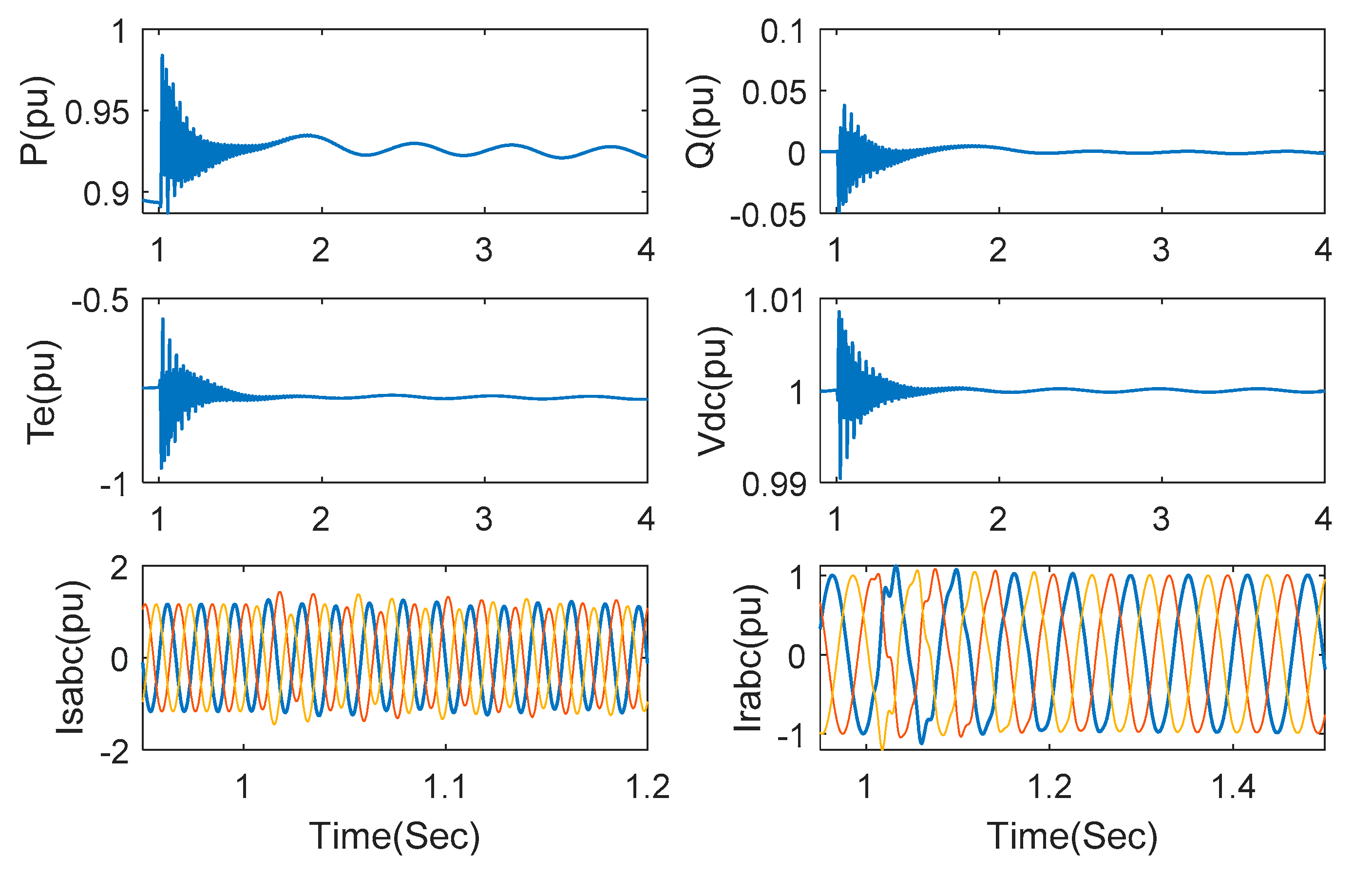
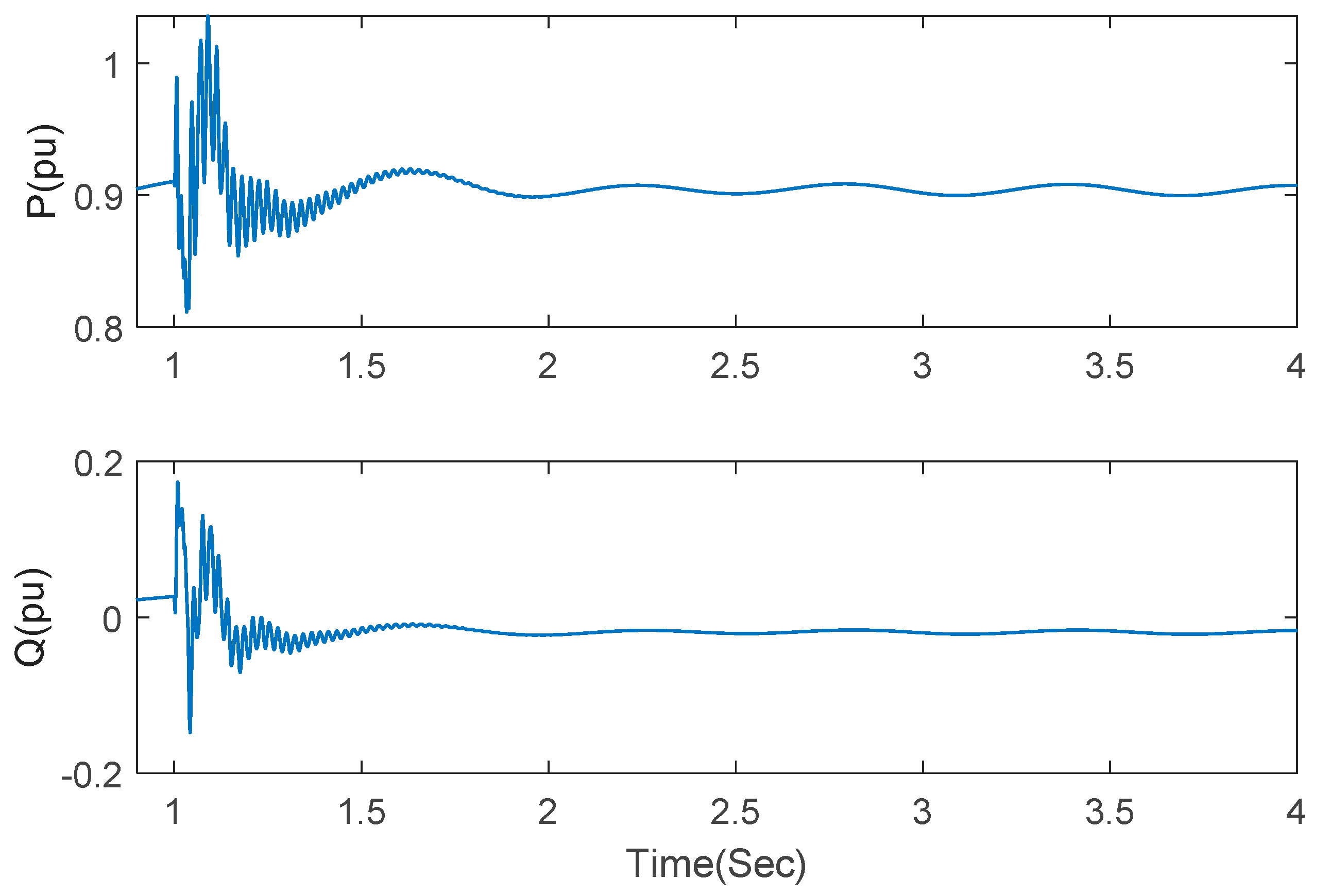
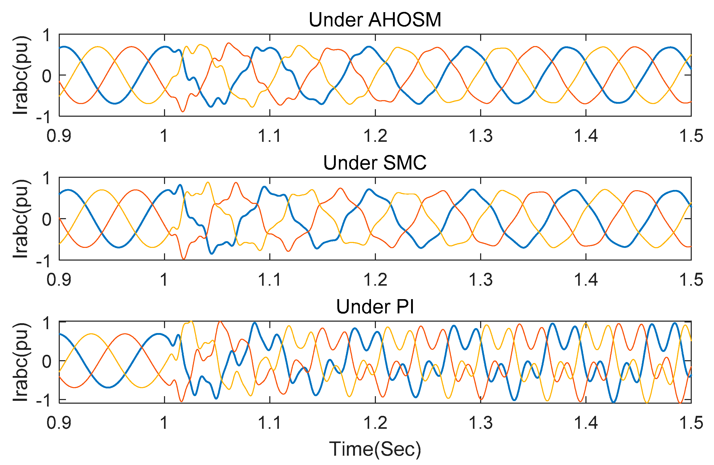
4. Time-Domain Simulation

It is hard to conduct experimental verification on large-scale, grid-connected wind farms due to a variety of practical constraints, as SSCI damping is too strong for small sets and SSCI is not easy to observe. Therefore, time-domain simulation is always the main measure to verify a control strategy for SSCI mitigation. In this paper, a grid-connected 100 MW wind farm is adopted as the study object to verify the effectiveness of the proposed control scheme under the MATLAB platform. PI control [10] and conventional first-order sliding mode control (SMC) [29] schemes are also executed to compare control performances. The model parameters are listed in Table 1. Relative adaptive parameters of the proposed AHOSM control method are chosen as μ q = 6.7 , η q = 0.026 , k q 1 = 3.2 , τ q 1 = 0.31 , μ d = 6.2 , η d = 0.03 , k d 1 = 2.1 , τ d 1 = 0.18 .
The classical double closed-loop PI control scheme and conventional first-order SMC scheme for comparison are shown in Figure 4 and Figure 5, respectively. The control parameters for PI controllers are set as K p = 0.1 , K Q = 0.83 , K i q = 1.2 , K i d = 5 , T p = 0.05 , T i q = 0.005 , T i d = 0.0025 which are mainly determined by the cut-and-trial method.
Conventional first-order SMC laws are represented as:
S r q = 2 L s u d c ( i r d ω 1 ( L m 2 L r r L s ) L m ( i s q R s u s q + L s i s d ω r ) + L s i r q R r r L r r L s i r d ω r   i ˙ r q * ( L m 2 L r r L s ) ρ i r q s i g n ( σ i r q ) ( L r r L s L m 2 )
S r d = 2 L s u d c ( i r q ω 1 ( L m 2 L r r L s ) + L m ( i s d R s + u s d + L s i s q ω r ) + L s i r d R r r + L r r L s i r q ω r   i ˙ r d * ( L m 2 L r r L s ) ρ i r d s i g n ( σ i r d ) ( L r r L s L m 2 )
where ρ i r q = 8.5 * 10 5 , ρ i r d = 2.3 * 10 6 .

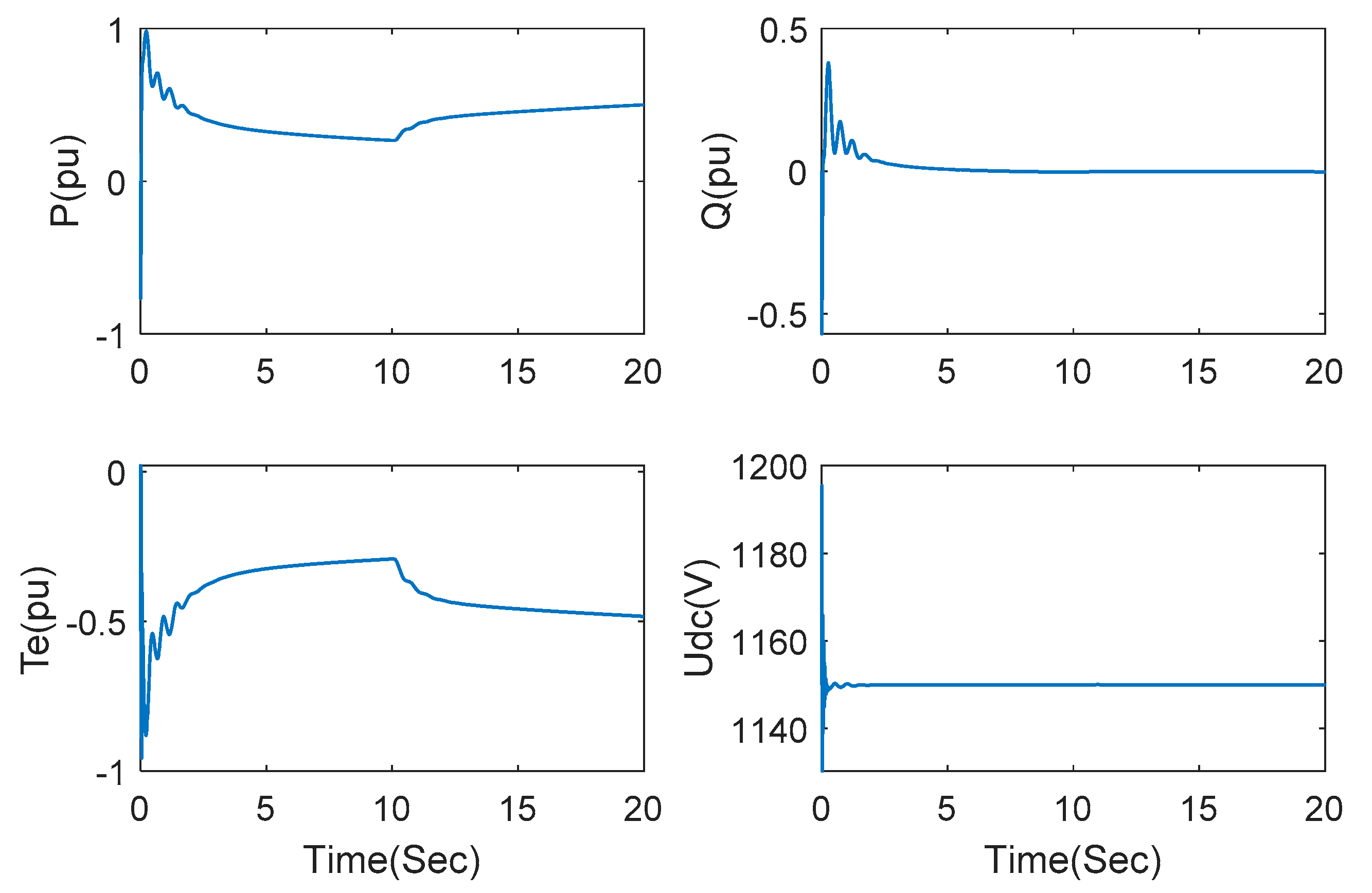
4.1. Control Performance Demonstration

In order to verify steady-state performance under the proposed AHOSM strategy, the wind speed of the wind farm is set as 7 m/s and increased to 9 m/s at 10 s when the series-compensated capacitor is not switched. The dynamic responses of active power, reactive power, electromagnetic torque and DC link voltage are demonstrated in Figure 6. Active power and electromagnetic torque can rapidly track wind speed variation, whereas reactive power and DC link voltage are hardly affected by wind speed, which means the decoupling control of active and reactive power is achieved.
Next, let us evaluate control performance under different series-compensated levels. Under the wind speed of 7 m/s, a series compensation of 40% is added at t = 1 s. The responses of active power, reactive power, electromagnetic torque, DC link voltage, stator current and rotor current are shown in Figure 7. Though SSCI occurs when the series-compensated capacitor is switched on, it is rapidly suppressed after 1.5 s. There is also oscillation observed in DC link voltage due to the influence of power fluctuation in converters, however, the oscillation can be rapidly suppressed, which indicates the validity of the proposed strategy for the voltage surge in DC link voltage. Stator current and rotor current are also shown in Figure 7 with a short transient time and small overshoot.
When wind speed is kept at 7 m/s and series compensation is increased to 75%, the responses of the relevant system variables are observed in Figure 8. Though the transient time is a little increased, SSCI can normally be suppressed.
The responses are demonstrated as Figure 9 when wind speed is increased to 15 m/s and the series-compensated level is set as 75%. Compared with Figure 8, it is observed that system damping is enhanced after the wind speed becomes bigger. SSCI can be removed after 1.8 s when the wind speed is 15 m/s.
The internal parameters of DFIG can be changed attributed to current variation and generator heating in a DFIG-based wind farm. The control performance can be severely influenced without proper control strategy. In order to evaluate robustness with regard to internal parameter perturbation, stator inductance Ls and RSC link impedance RRSC are both set to change with combined sine signals within their ± 50 % nominal values. The series compensation and wind speed are still fixed as 75% and 15 m/s, respectively. Compared with Figure 9, the responses, shown in Figure 10, have barely changed, which means good robustness for the internal parameter perturbation.
In practice, internal parameter perturbations and various external disturbances exist in a series-compensated system. In order to verify robustness for uncertainties, lumped uncertainties d r d and d r q in Formulas (16) and (17) are expressed as [34]:
{ d r d = 25 % f r d + 25 % g r d + 2 sin ( ω t ) d r q = 25 % f r q + 25 % g r q + 2 sin ( ω t )
Under the lumped uncertainties, the responses of active power, reactive power, electromagnetic torque, DC link voltage, stator current and rotor current are shown in Figure 11. These results verified the effectiveness for an uncertain wind power system.
In order to verify the fault ride-through capability of the proposed scheme, a symmetric (three-phase short circuit) fault and asymmetric (single line to ground) fault were respectively initiated at a high-voltage side of transformer at t = 1 s and cleared after 20 ms. The series-compensated system is operated under series compensation 75% and wind speed 13 m/s. The responses of active power and reactive power are shown as Figure 12 and Figure 13. SSCI can be mitigated after fault is cleared under the two fault conditions.

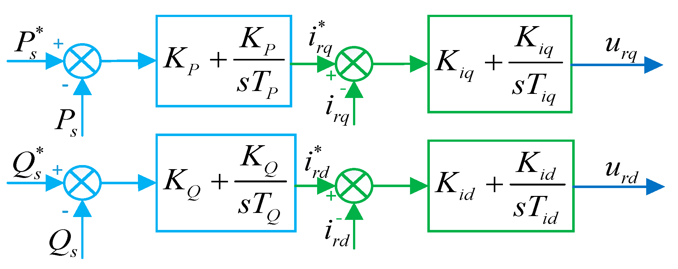
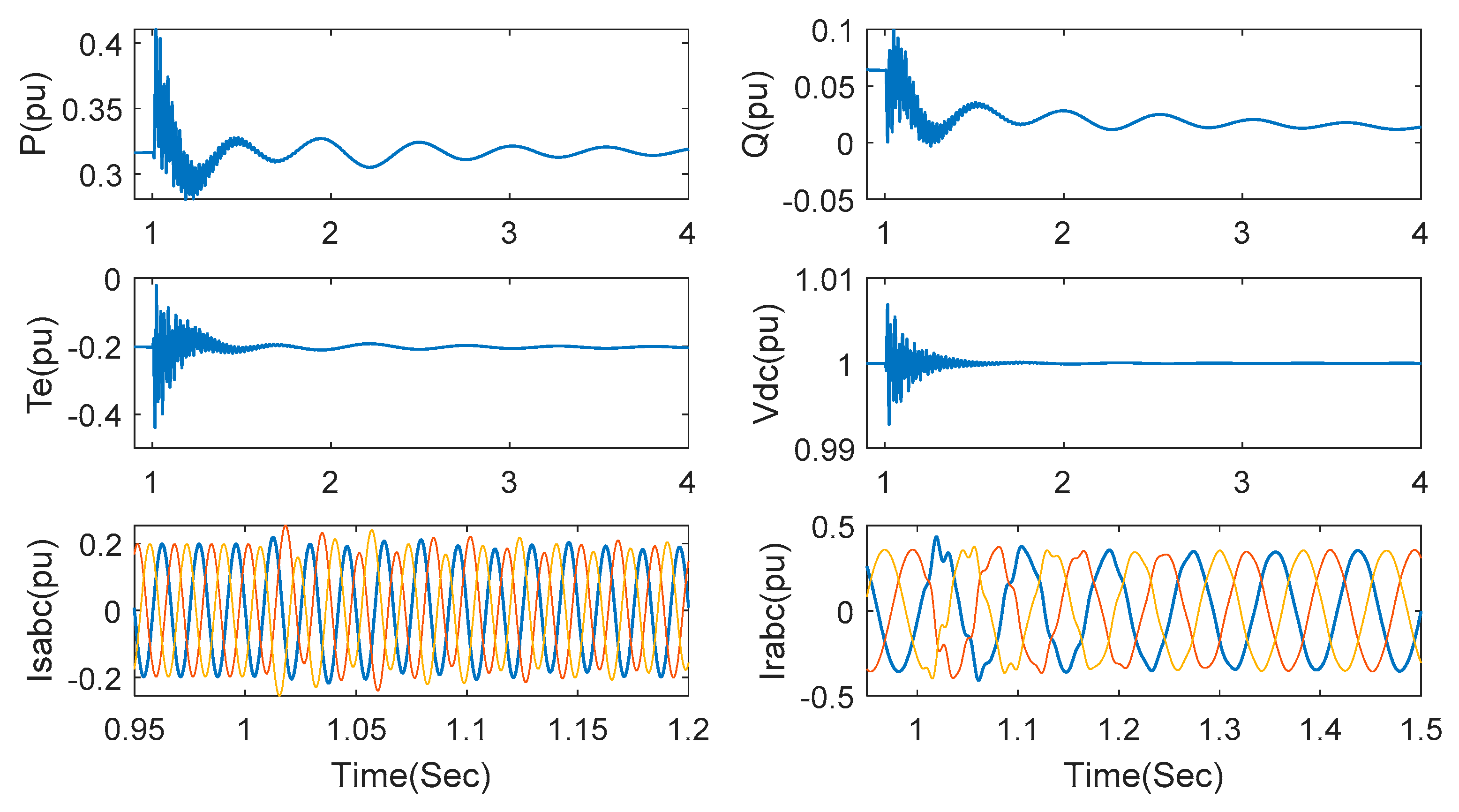
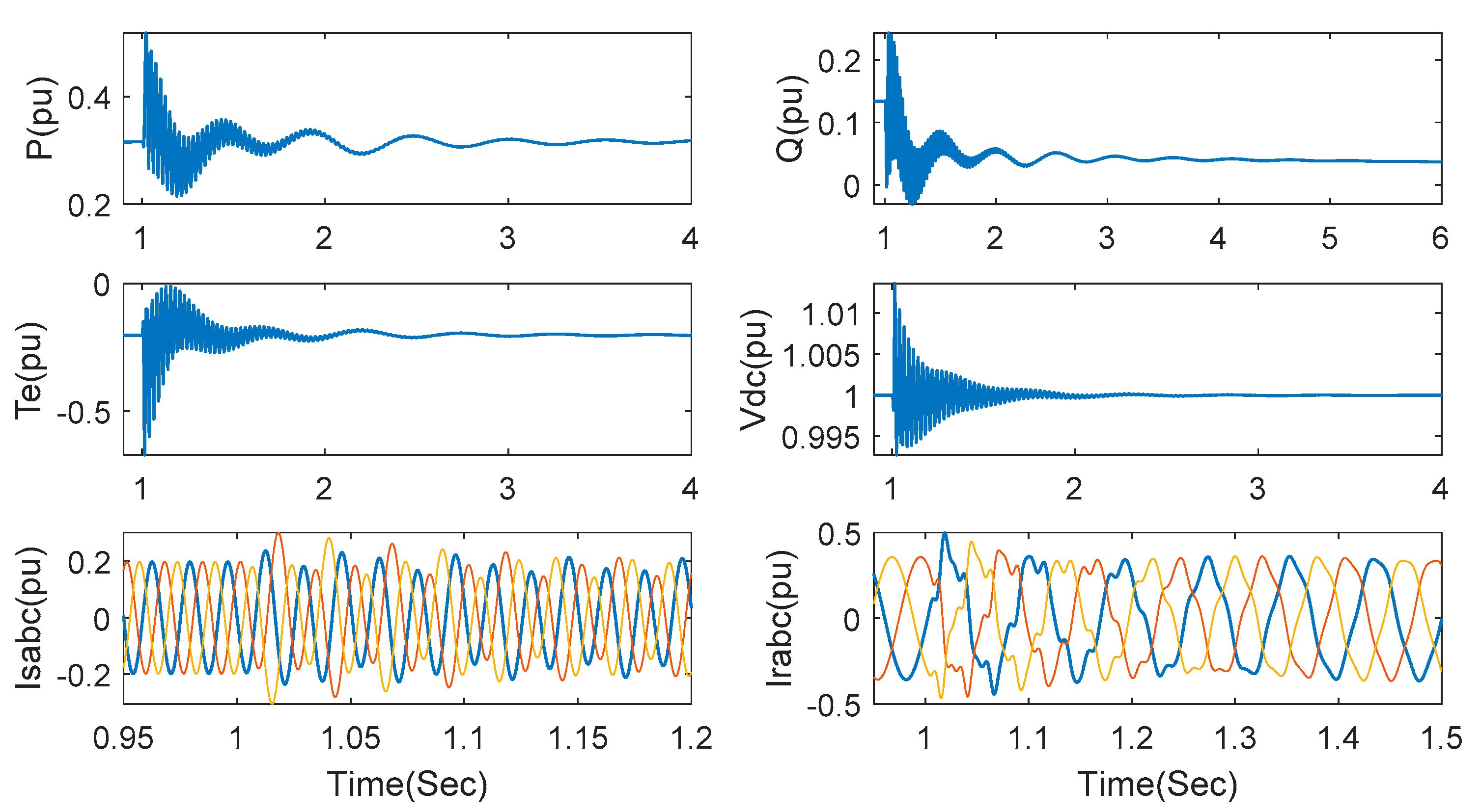
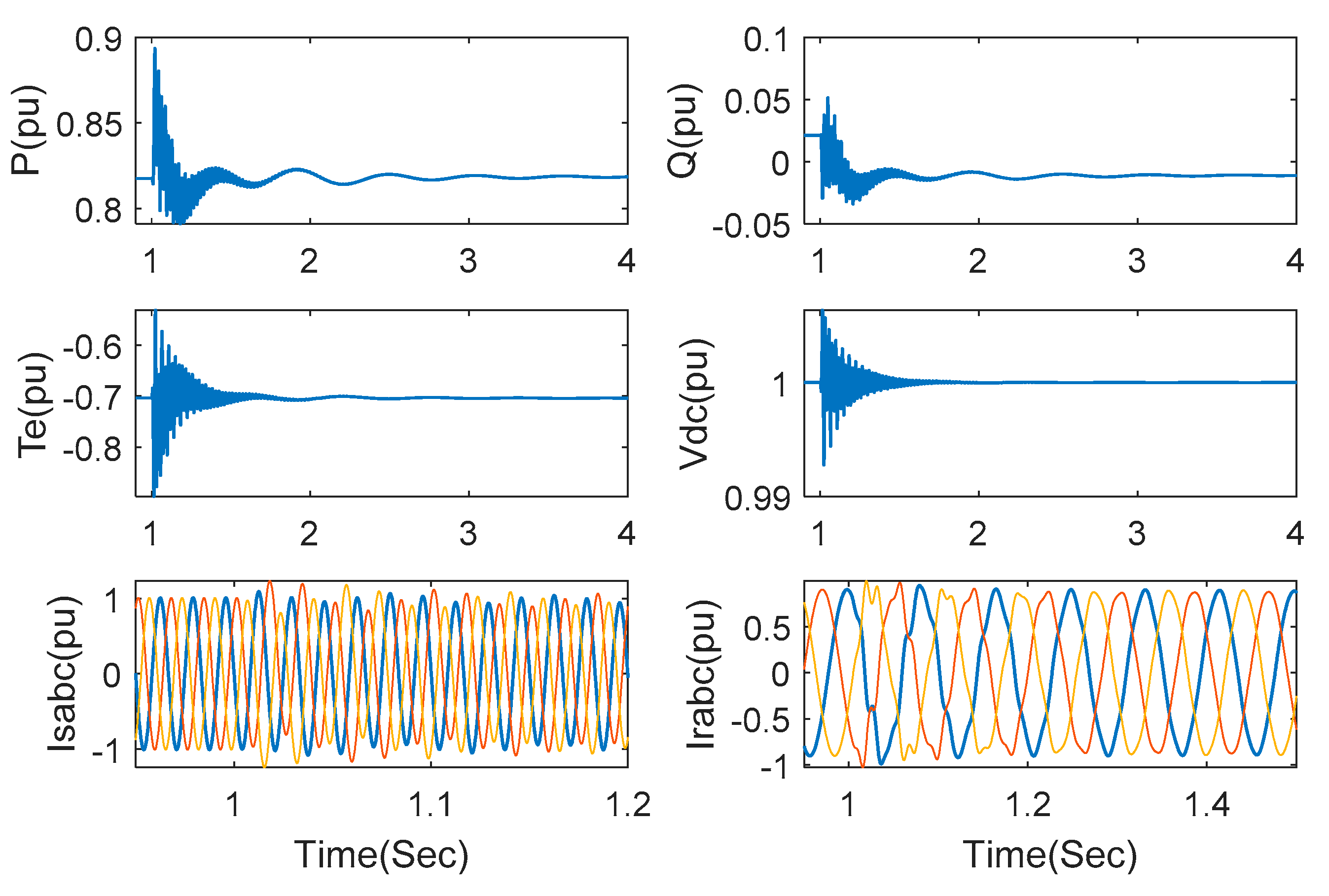
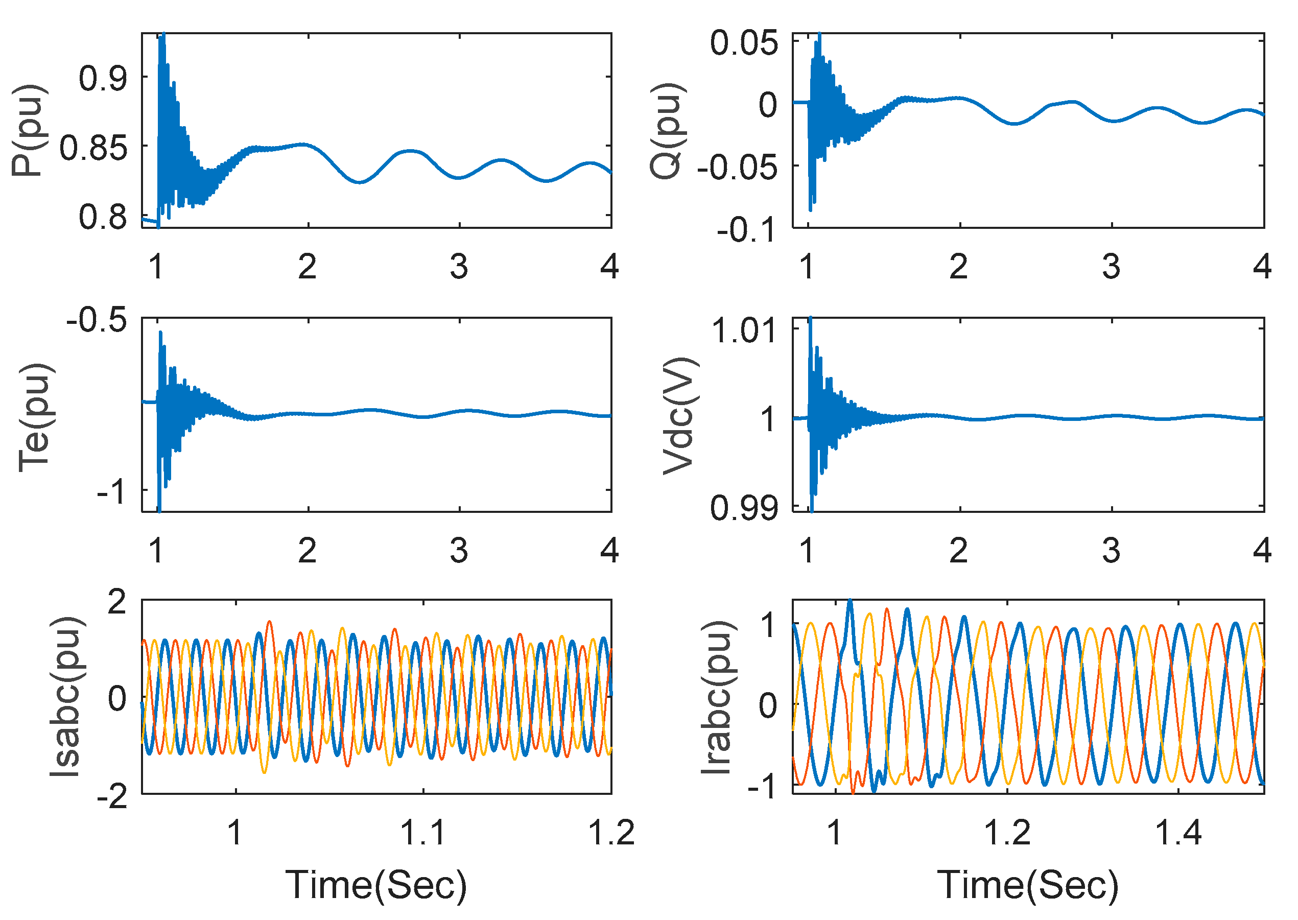
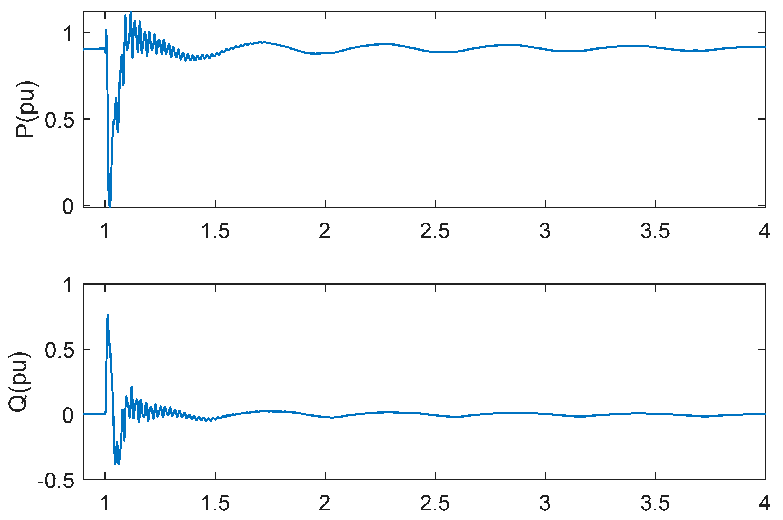
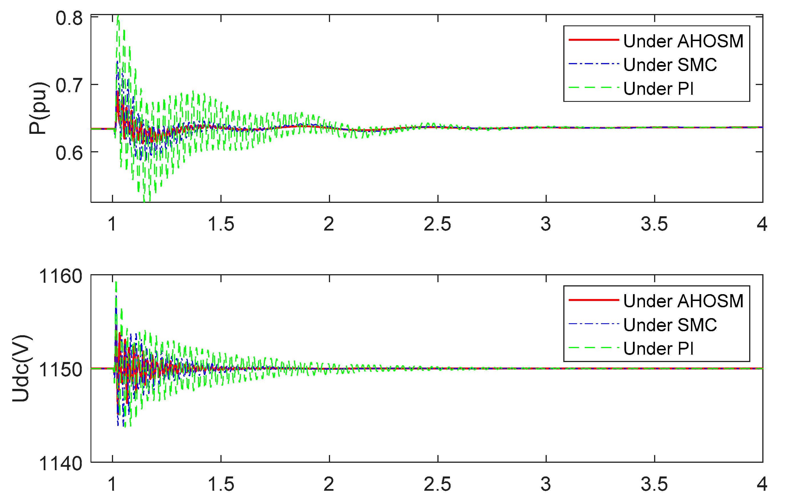
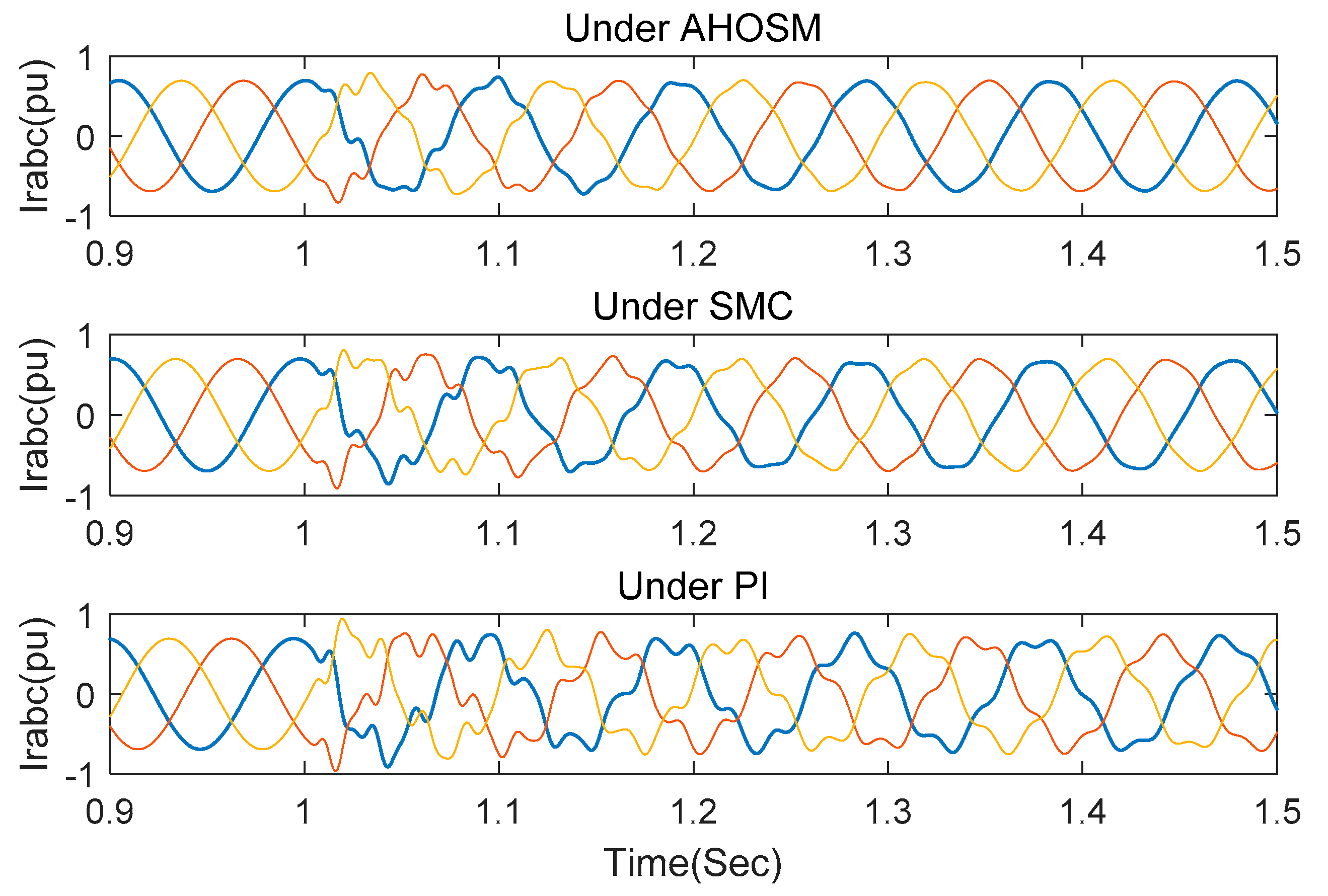
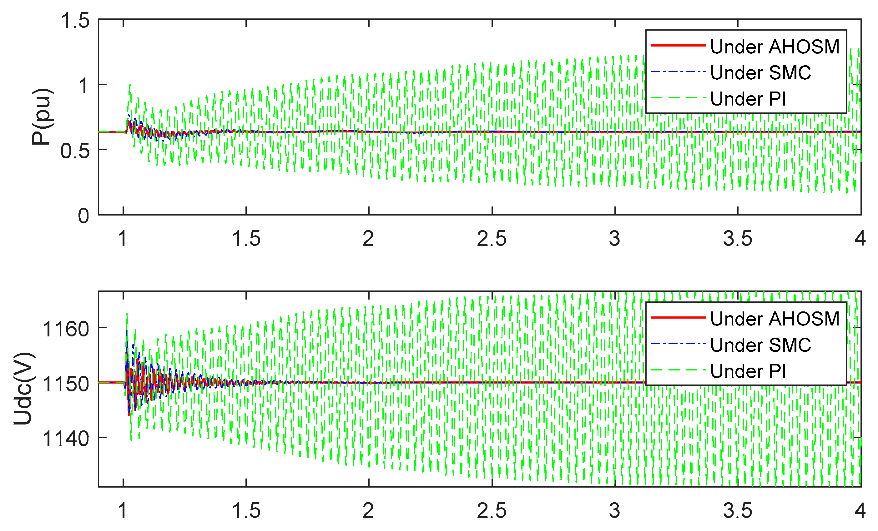
4.2. Comparison with PI and SMC Method

In this section, simulations under PI and SMC method are also executed to compare control-damping performance. Wind speed is set as 11 m/s, and series-compensated level is 30%. Stator inductance Ls and RSC link impedance RRSC still change within their ± 50 % nominal values. Figure 14 are the response curves of active power and DC link voltage. It is indicated that oscillation can be suppressed under the three control schemes. Transient time and overshoot are the smallest under the proposed AHOSM method, which is followed by the SMC and PI methods. The regulating processes of rotor currents are shown in Figure 15, demonstrating the shortest regulating time under the proposed method.
When the series-compensated level is increased to 70%, the responses have already diverged under PI method, as shown in Figure 16 and Figure 17. Oscillation can be effectively mitigated under SMC and proposed AHOSM methods. The suppression effect of the proposed method is relatively better, and the most important thing is that there is no need to know the upper bound of uncertainty derivative. Control gains in the proposed AHOSM control can change according to system uncertainties, and the adaptive process of the control parameters are shown in Figure 18.
For evaluating the control performance, two indices have been defined as follows:
R M S e i = 1 n s k = 1 n s e i 2 ,   R M S u i = 1 n s k = 1 n s u i 2
where n s , e i , u i are the number of samples, root mean square (RMS) of tracking errors and control quantities.
When the studied system works with a series-compensated level of 70% and a wind speed of 11 m/s, the RMS for tracking errors and control quantities are shown in Table 2, which exhibit the superiority of the proposed AHOSM method.

5. Conclusions

In this paper, a new SSCI mitigation scheme for an uncertain, nonlinear, series-compensated, DFIG-based wind-power system is proposed based on the AHOSM method. The prescribed rotor current dynamics are tracked according to MPPT and reactive power demand, and problematic rotor dynamics are suppressed by collapsing them into algebraic equations. The control scheme is achieved based on feedback control and second-order sliding mode control. Adaptive super-twisting control gains removed the need for an upper bound of the uncertainty derivative. The decoupling control of power is also completed well. Simulations under different conditions, and comparisons with PI and SMC schemes, verify its effectiveness and superiority. Future work will focus on the physical verification of the proposed control scheme.

Author Contributions

Conceptualization, Y.H.; Funding acquisition, Y.H.; Methodology, Y.H.; Software, S.L.; Validation, S.L. and C.D.; Writing—original draft, Y.H.; Writing—review and editing, S.L. and C.D. All authors have read and agreed to the published version of the manuscript.

Funding

This research was funded by National Natural Science Foundation of China under Grant number 61803230; A Project of Shandong Province Higher Educational Science and Technology Program under Grant number J18KA330 and University outstanding youth innovation team development plan of Shandong Province under Grant number 2019KJN023.

Conflicts of Interest

The authors declare no conflict of interest.

References

  1. Bounar, N.; Labdai, S.; Boulkroune, A. PSO–GSA based fuzzy sliding mode controller for DFIG-based wind turbine. ISA Trans. 2019, 85, 177–188. [Google Scholar] [CrossRef] [PubMed]
  2. Du, W.; Fu, Q.; Wang, H. Power System Small-Signal Angular Stability Affected by Virtual Synchronous Generators. IEEE Trans. Power Syst. 2019, 34, 3209–3219. [Google Scholar] [CrossRef]
  3. Chernet, S.; Beza, M.B.; Bongiorno, M. Investigation of subsynchronous control interaction in DFIG-based wind farms connected to a series compensated transmission line. Int. J. Electr. Power Energy Syst. 2019, 105, 765–774. [Google Scholar] [CrossRef]
  4. Zhang, X.; Xie, X.; Shair, J.; Liu, H.; Li, Y.; Li, Y. A Grid-Side Subsynchronous Damping Controller to Mitigate Unstable SSCI and Its Hardware-in-the-loop Tests. IEEE Trans. Sustain. Energy 2019, 11, 1548–1558. [Google Scholar] [CrossRef]
  5. Ghafouri, M.; Karaagac, U.; Karimi, H.; Mahseredjian, J. Robust subsynchronous interaction damping controller for DFIG-based wind farms. J. Mod. Power Syst. Clean Energy 2019, 7, 1663–1674. [Google Scholar] [CrossRef] [Green Version]
  6. Xie, X.; Zhang, X.; Liu, H.; Liu, H.; Li, Y.; Zhang, C. Characteristic Analysis of Subsynchronous Resonance in Practical Wind Farms Connected to Series-Compensated Transmissions. IEEE Trans. Energy Convers. 2017, 32, 1117–1126. [Google Scholar] [CrossRef]
  7. Revel, G.; Alonso, D.M. Subsynchronous interactions in power networks with multiple DFIG-based wind farms. Electr. Power Syst. Res. 2018, 165, 179–190. [Google Scholar] [CrossRef]
  8. Fan, L.; Zhu, C.; Miao, Z.; Hu, M. Modal Analysis of a DFIG-Based Wind Farm Interfaced With a Series Compensated Network. IEEE Trans. Energy Convers. 2011, 26, 1010–1020. [Google Scholar] [CrossRef]
  9. He, C.; Sun, D.; Song, L.; Ma, L. Analysis of Subsynchronous Resonance Characteristics and Influence Factors in a Series Compensated Transmission System. Energies 2019, 12, 3282. [Google Scholar] [CrossRef] [Green Version]
  10. Fan, L.; Miao, Z. Mitigating SSR Using DFIG-Based Wind Generation. IEEE Trans. Sustain. Energy 2012, 3, 349–358. [Google Scholar] [CrossRef]
  11. Li, Y.; Fan, L.; Miao, Z. Replicating Real-World Wind Farm SSR Events. IEEE Trans. Power Deliv. 2020, 35, 339–348. [Google Scholar] [CrossRef]
  12. Ghaffarzadeh, H.; Mehrizi-Sani, A. Mitigation of Subsynchronous Resonance Induced by a Type III Wind System. IEEE Trans. Sustain. Energy 2019, 11, 1717–1727. [Google Scholar] [CrossRef]
  13. Yao, J.; Wang, X.; Li, J.; Liu, R.; Zhang, H. Sub-Synchronous Resonance Damping Control for Series-Compensated DFIG-Based Wind Farm with Improved Particle Swarm Optimization Algorithm. IEEE Trans. Energy Convers. 2019, 34, 849–859. [Google Scholar] [CrossRef]
  14. Ghafouri, M.; Karaagac, U.; Karimi, H.; Jensen, S.; Mahseredjian, J.; Faried, S.O. An LQR Controller for Damping of Subsynchronous Interaction in DFIG-Based Wind Farms. IEEE Trans. Power Syst. 2017, 32, 1. [Google Scholar] [CrossRef]
  15. Yang, J.-W.; Sun, X.-F.; Chen, F.-H.; Liao, K.; He, Z.-Y. Subsynchronous resonance suppression strategy for doubly fed induction generators based on phase-shift average of rotor current. Int. Trans. Electr. Energy Syst. 2019, 29, e2831. [Google Scholar] [CrossRef]
  16. Chen, A.; Xie, D.; Zhang, D.; Gu, C.; Wang, K. PI Parameter Tuning of Converters for Sub-Synchronous Interactions Existing in Grid-Connected DFIG Wind Turbines. IEEE Trans. Power Electron. 2018, 34, 6345–6355. [Google Scholar] [CrossRef]
  17. Chowdhury, A.; Mahmud, A.; Shen, W.; Pota, H.R. Nonlinear Controller Design for Series-Compensated DFIG-Based Wind Farms to Mitigate Subsynchronous Control Interaction. IEEE Trans. Energy Convers. 2017, 32, 707–719. [Google Scholar] [CrossRef]
  18. Chowdhury, M.A.; Shafiullah, G. SSR Mitigation of Series-Compensated DFIG Wind Farms by a Nonlinear Damping Controller Using Partial Feedback Linearization. IEEE Trans. Power Syst. 2017, 33, 2528–2538. [Google Scholar] [CrossRef]
  19. Li, P.; Wang, J.; Wu, F.; Li, H. Nonlinear controller based on state feedback linearization for series-compensated DFIG-based wind power plants to mitigate sub-synchronous control interaction. Int. Trans. Electr. Energy Syst. 2018, 29, e2682. [Google Scholar] [CrossRef] [Green Version]
  20. Wang, Y.; Wu, Q.; Yang, R.; Tao, G.; Liu, Z. H∞ current damping control of DFIG based wind farm for sub-synchronous control interaction mitigation. Int. J. Electr. Power Energy Syst. 2018, 98, 509–519. [Google Scholar] [CrossRef]
  21. Xu, Y.; Zhao, S. Mitigation of Subsynchronous Resonance in Series-Compensated DFIG Wind Farm Using Active Disturbance Rejection Control. IEEE Access 2019, 7, 68812–68822. [Google Scholar] [CrossRef]
  22. Ding, S.; Park, J.H.; Chen, C.-C. Second-order sliding mode controller design with output constraint. Automatica 2020, 112, 108704. [Google Scholar] [CrossRef]
  23. Vidal, P.V.N.M.; Nunes, E.V.L.; Hsu, L. Output-Feedback Multivariable Global Variable Gain Super-Twisting Algorithm. IEEE Trans. Autom. Control. 2016, 62, 2999–3005. [Google Scholar] [CrossRef]
  24. Liu, Y.; Wang, Z.; Xiong, L.; Wang, J.; Jiang, X.; Bai, G.; Li, R.; Liu, S. DFIG wind turbine sliding mode control with exponential reaching law under variable wind speed. Int. J. Electr. Power Energy Syst. 2018, 96, 253–260. [Google Scholar] [CrossRef]
  25. Han, Y.; Ma, R. Adaptive-Gain Second-Order Sliding Mode Direct Power Control for Wind-Turbine-Driven DFIG under Balanced and Unbalanced Grid Voltage. Energies 2019, 12, 3886. [Google Scholar] [CrossRef] [Green Version]
  26. Merabet, A.; Eshaft, H.; Tanvir, A.A. Power-current controller based sliding mode control for DFIG-wind energy conversion system. IET Renew. Power Gener. 2018, 12, 1155–1163. [Google Scholar] [CrossRef]
  27. Li, P.; Xiong, L.; Wu, F.; Ma, M.; Wang, J. Sliding mode controller based on feedback linearization for damping of sub-synchronous control interaction in DFIG-based wind power plants. Int. J. Electr. Power Energy Syst. 2019, 107, 239–250. [Google Scholar] [CrossRef]
  28. Li, P.; Wang, J.; Xiong, L.; Ma, M. Robust Nonlinear Controller Design for Damping of Sub-Synchronous Control Interaction in DFIG-Based Wind Farms. IEEE Access 2019, 7, 16626–16637. [Google Scholar] [CrossRef]
  29. Karunanayake, C.; Ravishankar, J.; Dong, Z.Y. Nonlinear SSR Damping Controller for DFIG Based Wind Generators Interfaced to Series Compensated Transmission Systems. IEEE Trans. Power Syst. 2020, 35, 1156–1165. [Google Scholar] [CrossRef]
  30. Utkin, V. Discussion Aspects of High-Order Sliding Mode Control. IEEE Trans. Autom. Control. 2015, 61, 829–833. [Google Scholar] [CrossRef]
  31. Levant, A.; Shustin, B. Quasi-Continuous MIMO Sliding-Mode Control. IEEE Trans. Autom. Control. 2018, 63, 3068–3074. [Google Scholar] [CrossRef]
  32. Sadeghi, R.; Madani, S.M.; Ataei, M.; Kashkooli, M.R.A.; Ademi, S. Super-Twisting Sliding Mode Direct Power Control of a Brushless Doubly Fed Induction Generator. IEEE Trans. Ind. Electron. 2018, 65, 9147–9156. [Google Scholar] [CrossRef]
  33. Zhao, Y.; Huang, P.; Zhang, F.; Meng, Z. Contact Dynamics and Control for Tethered Space Net Robot. IEEE Trans. Aerosp. Electron. Syst. 2018, 55, 918–929. [Google Scholar] [CrossRef]
  34. Sami, I.; Ullah, S.; Ali, Z.; Ullah, N.; Ro, J.-S. A Super Twisting Fractional Order Terminal Sliding Mode Control for DFIG-Based Wind Energy Conversion System. Energies 2020, 13, 2158. [Google Scholar] [CrossRef]
Figure 1. Series-compensated DFIG-based wind farm grid-connected system.
Energies 13 05421 g001
Figure 2. Schematic diagram of the generation process of sub-synchronous control interaction (SSCI).
Energies 13 05421 g002
Figure 3. Control structure of the proposed adaptive higher-order sliding model (AHOSM) control scheme.
Energies 13 05421 g003
Figure 4. Control structure of PI scheme.
Energies 13 05421 g004
Figure 5. Conventional first-order sliding mode control (SMC) scheme.
Energies 13 05421 g005
Figure 6. Responses of active power, reactive power, electromagnetic torque, DC link voltage with no series-compensated capacitors.
Energies 13 05421 g006
Figure 7. Responses under the proposed method with series compensation 35% and wind speed 7 m/s.
Energies 13 05421 g007
Figure 8. Responses under the proposed method with series compensation 75% and wind speed 7 m/s.
Energies 13 05421 g008
Figure 9. Responses under the proposed method with series compensation 75% and wind speed 15 m/s.
Energies 13 05421 g009
Figure 10. Responses under the proposed method with internal parameter perturbation (series compensation 75% and wind speed 15 m/s).
Energies 13 05421 g010
Figure 11. Responses under the proposed method with lumped uncertainties (series compensation 75% and wind speed 15 m/s).
Energies 13 05421 g011
Figure 12. Responses of active power and reactive power under three-phase short circuit fault in series-compensated wind farm.
Energies 13 05421 g012
Figure 13. Responses of active power and reactive power under asymmetric fault in series-compensated wind farm.
Energies 13 05421 g013
Figure 14. Responses of active power and DC link voltage under three control methods with series-compensated level 30% and wind speed 11 m/s.
Energies 13 05421 g014
Figure 15. Responses of current rotor under three control methods with series-compensated level 30% and wind speed 11 m/s.
Energies 13 05421 g015
Figure 16. Responses of active power and DC link voltage under three control methods with series-compensated level 70% and wind speed 11 m/s.
Energies 13 05421 g016
Figure 17. Responses of rotor under three control methods with series-compensated level 70% and wind speed 11 m/s.
Energies 13 05421 g017
Figure 18. Adaptive control gains.
Energies 13 05421 g018
Table 1. Parameters of series-compensated DFIG-based wind farm.
QuantityValue
Nominal power (MW)100
Rater voltage (V)690
Rs (pu)0.0084
Ls (pu)0.167
HT (pu)2.5
HG (pu)0.5
Ks (pu)0.15
RRSC (pu)0.0083
LRSC (pu)0.1323
RGSC (pu)0.0015
LGSC (pu)0.151
DC link capacitance (mF)10
Nominal DC link voltage (V)1150
RL (pu)0.02
LL (pu)0.0016
CSC(at 45% compensation) (uF)42.61
Table 2. RMS for tracking errors and control quantities.
RMSurqRMSurdRMSeirqRMSeird
PI0.98570.91720.06720.0712
SMC0.77190.71830.05330.0602
AHOSM0.53160.50290.03710.0392
Publisher’s Note: MDPI stays neutral with regard to jurisdictional claims in published maps and institutional affiliations.

