Abstract
In this paper, we propose a novel study concerning the future use of a zero-airgap induction motor in applications related to transmission oil pumps. The name of the machine comes from the fact that the rotor touches the stator as it spins. The use of such an eccentric motor provides the possibility to remove the mechanical part that is typically found in the transmission oil pump, increasing its efficiency in this way. We focused on determining the optimum variant of a zero-airgap small power induction motor from the point of view of the electrical and mechanical performance. As such, 18 topologies of induction motors with various numbers of pole pairs and rotor bars were designed and numerically analyzed. For the best variant from each category, different eccentricities were considered to evaluate this effect over the performances of the motors. For the best candidate, various analyses were performed in order to demonstrate the validity of this solution for the proposed application. Elements regarding the thermal analysis of this structure are also presented here.
1. Introduction
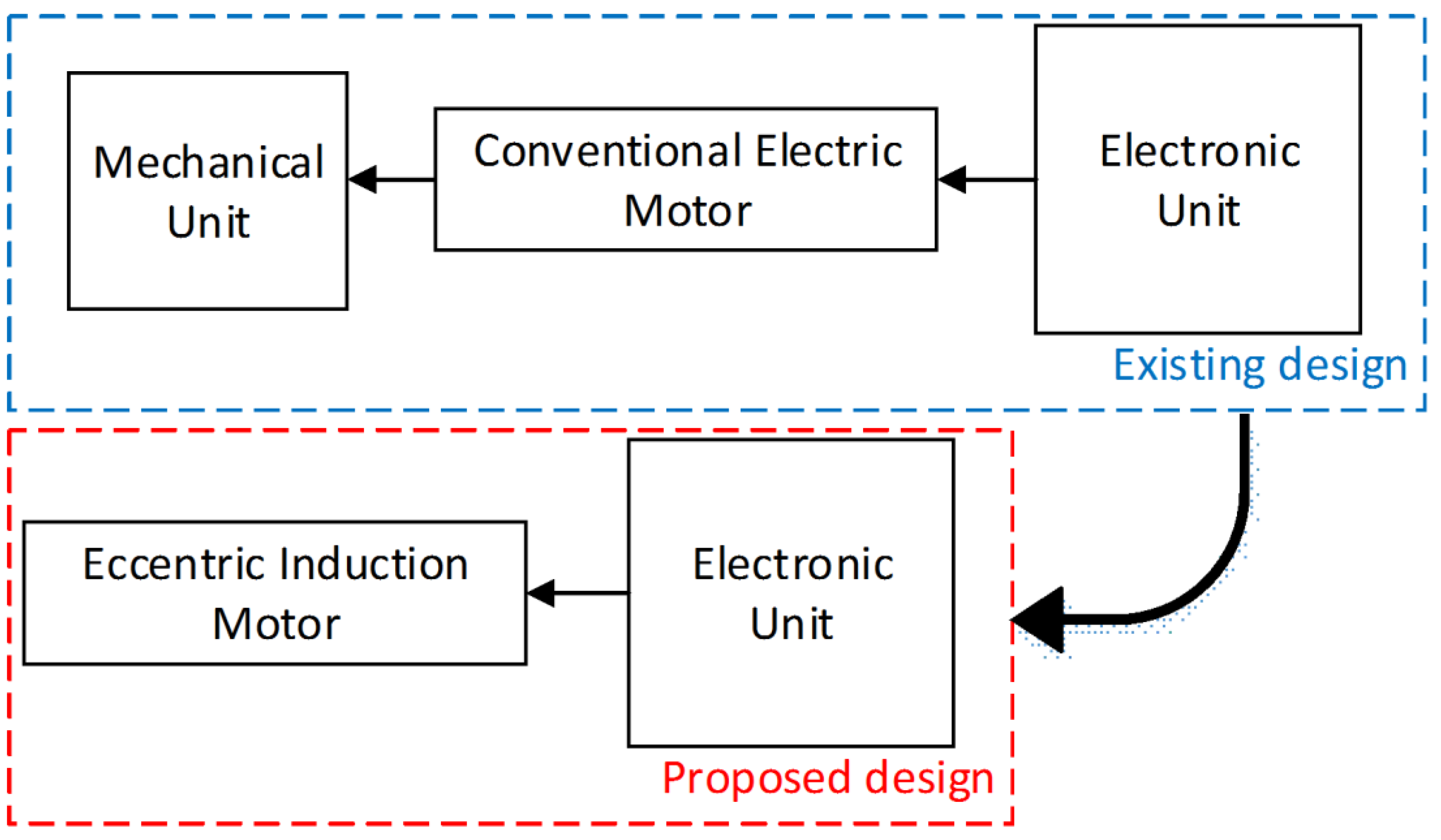
The fast development of hybrid electrical vehicles in parallel configuration, for the comfort of passengers, results in a complex and comprehensive electro-mechanical-hydraulic system for the gearbox. Therefore, all modern gearboxes are equipped with electric pumps [1,2,3]. There are four types of pumping mechanisms used for transmission oil pumps: sliding vane, side channel, screw(s) mechanisms, and several versions of the toothed ring mechanisms. Due to its better performance, the latter of these is the most commonly used oil pump. However, such pumps require the usage of a supplementary mechanism in order to obtain the eccentric movement specific to such pumps. In order to simplify the pump complexity, in this paper, we investigate the idea of an eccentric electric motor that could directly drive the pump, with positive effects toward the price, size, weight, and reliability of the assembly, as presented in Figure 1.

Figure 1.
Block diagram of the transmission oil pump driving system.
Until now, the majority of studies focused on the oil pump as a whole system [1,2,4]. The first mass-produced electric pumps for automotive applications, especially for oil transmission and fuel pumps, were driven ubiquitously by DC motors, with and without permanent magnets [3,5]. However, the conventional DC motors are less used due to their brushed system. In [6,7], a permanent magnet motor (PMSM) for such a transmission oil pump was presented. In [8], the authors designed and compared, in terms of the performance and cost, two PMSMs with different topologies used for oil pumps.
An induction machine with an eccentric rotor is studied here. The majority of the studies in this research area deal with eccentricity as a fault of the machine. An analytical approach to evaluate the performance of a three-phase induction motor (IM) under mixed eccentric conditions is presented in [9]. An evaluation of the negative influence of the eccentricity is given in [10]. A control scheme to reduce the effects of eccentricity in a three phase IM is proposed in [11]. An analytical model for a cage IM with a static eccentric rotor is presented in [12].
In [13], a special case was presented where a new category of electric motors were able to generate high torque with reduced volume, i.e., high torque density. This topology is in fact an airgap-less electrical motor as the rotor touches the stator, hence its name, zero-airgap machine. The zero-airgap motor is the extreme case of that with an eccentric rotor. In [14], the same machine was built as a proof-of-concept. The mechanical solution for these structures is detailed in [15].
The aim of this paper was to investigate the electrical (current, efficiency, power factor, etc.) and mechanical (torque value and ripple) performances of different topologies with a small power zero-airgap induction motor (ZAIM) suitable for a transmission oil pump. As stated before, the concept of the airgap-less electric motor was already validated experimentally; however, the novelty of this study resides in the idea to use an eccentric induction motor for such an application.
In Section 2, several conventional IM topologies are designed and numerically analyzed to evaluate their mechanical performances. Then, different eccentricities are applied to the best models. The design procedure of ZAIM is based on that of the conventional IM, but one must consider that the increase in the eccentricity leads to an increase in the current. Thus, the starting values for the current density must be taken accordingly [16], as will be shown. For accurate comparison, all the obtained results for each eccentric topology are compared by means of the finite element method with the non-eccentric type in Section 3. Conclusions regarding the presented results show the feasibility of the proposed innovative solution.
2. Design of IM for the Transmission Oil Pump
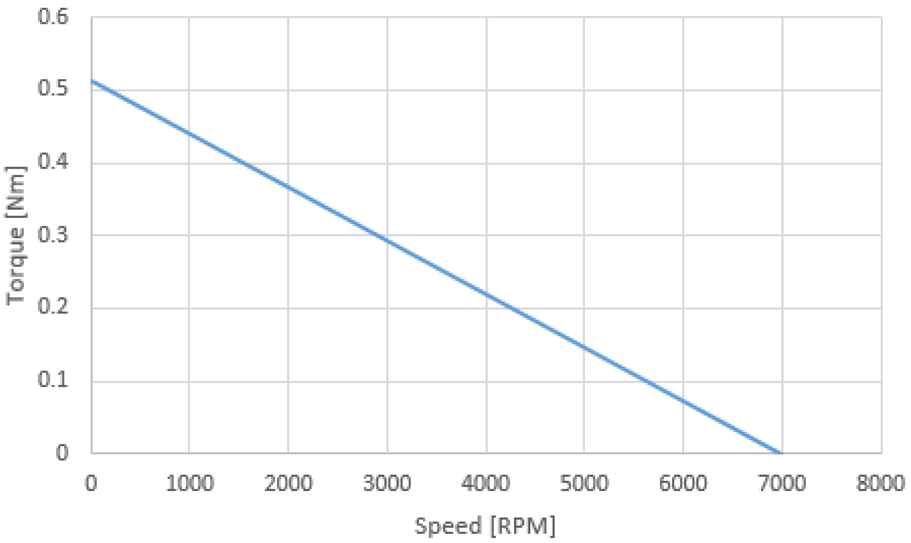
The starting point of this study is the torque vs. speed characteristic of an equivalent DC motor used in an oil pump as shown in Figure 2. The main data of this motor are PN = 100 W, UN = 12 V, IN = 12.8 A, nN = 3000 rpm, outer diameter 103 mm, and axial length 40 mm.
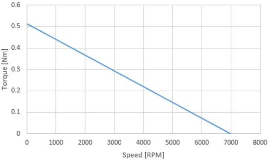
Figure 2.
Torque vs. speed characteristic of a DC motor used in pump applications.
The main shortcomings of the traditional candidate for this application (the permanent magnet DC machines) makes them less viable for this application as such an application implies the existence of relatively high temperatures; therefore, the use of permanent magnets would not be recommended.
Due to the robustness, reliability, and high-power density, the IM was chosen to evaluate the working performances in automotive applications, like volumetric transmission oil pumps. Thus, we investigated a topology with a classical squirrel cage rotor.
The eccentricity is defined here as the displacement of the rotor axis with respect to the stator axis. Figure 3 shows the structure of a ZAIM both in 3D perspective and as a cross section of the iron core.
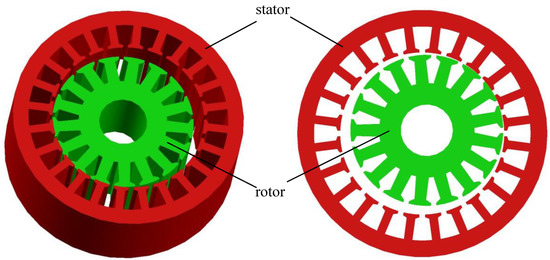
Figure 3.
Three-dimensional view and cross section of a zero-airgap induction motor (ZAIM) iron core.
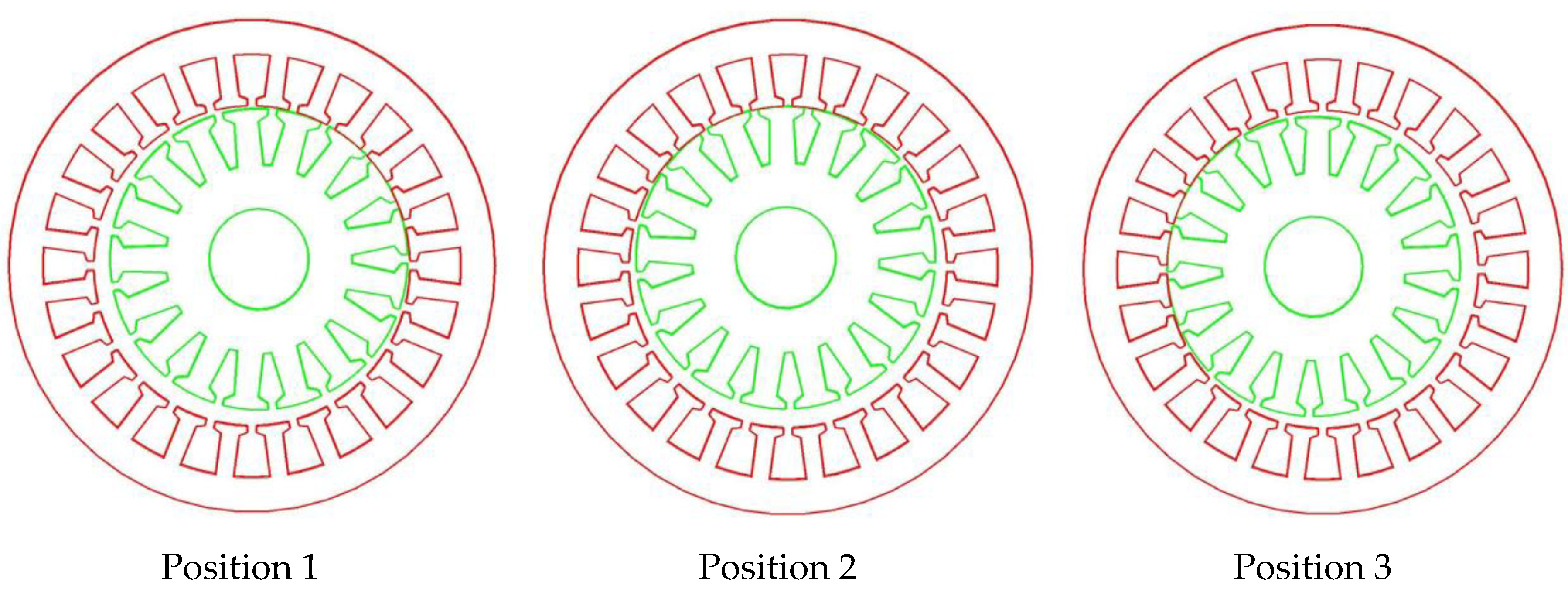
The rotation of an eccentric motor is similar to that of a hydraulic motor [14]. As shown in Figure 3, the rotor touches the stator at only one point, in the cross section. Therefore, in this case, the rotor performs two types of rotations: around its own axis and around the axis of the stator. Three successive positions, considering the clockwise rotation of the rotor, as shown in Figure 4, illustrate the operating principle of ZAIM.
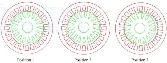
Figure 4.
Sequence of shots showing a continuous rotor movement.
The operating principle of ZAIM is essentially the same as that of a conventional IM [16]. The ZAIM considered for this application is immersed in automatic transmission fluid (ATF—type DEX3). The rotation movement of the rotor inside the stator is pure rolling without mechanical slip [14] under very good lubrication. The maximum value of the coefficient of rolling friction in this case is 0.002 [17].
Based on this concept, several variants of conventional induction machines (IMs) that can satisfy these requirements were designed. As the torque behavior shown in Figure 2 is not specific for an IM, all these models are overdesigned to ensure that the operation envelope will fully cover the requirements in absolute values. As such, if the characteristic shown in Figure 2 is strictly desired, then the control system should derate the motor(s) accordingly.
The main imposed data in the design procedure of the IM are given in Table 1.

Table 1.
Imposed data in the design procedure of the induction machines (IMs).
The maximum rms voltage is obtained from the DC bus using “H” bridge inverters. However, this value of the supply voltage should be applied when the machine operates at the rated speed and over. At lower speeds, one must reduce the AC voltage in order to maintain (in an ideal case) a U/f ratio constant; although, due the small size of the machine, this behavior would be quite nonlinear. As such, at 1500 rpm, the supply voltage will be around 5 V rms, which sets the base data of the project for initial sizing purposes only.
The IMs were designed starting from indicative values of the power factor and efficiency for this range of power and number of pole pairs. As mentioned above, in order to overdesign the IMs, relatively low values for power factor and efficiency (0.65) were considered at the start of the design procedure. The precise value of the current was obtained from the numerical analysis based on finite element method (FEM) and, consequently, the value of the current density.
In Table 2, the active materials used for the IM are presented.
Table 2.
Active materials used for IM and their characteristics.
The magnetization curve for the magnetic material used for the IM iron core is presented in Figure 5.
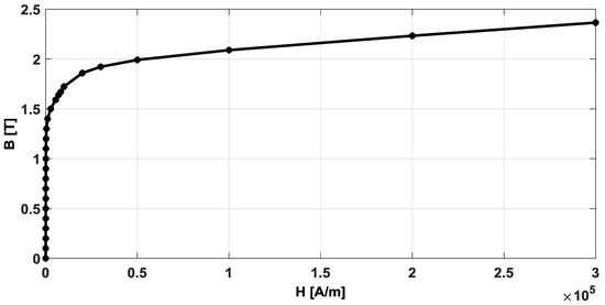
Figure 5.
Magnetization curve for M270-35A.
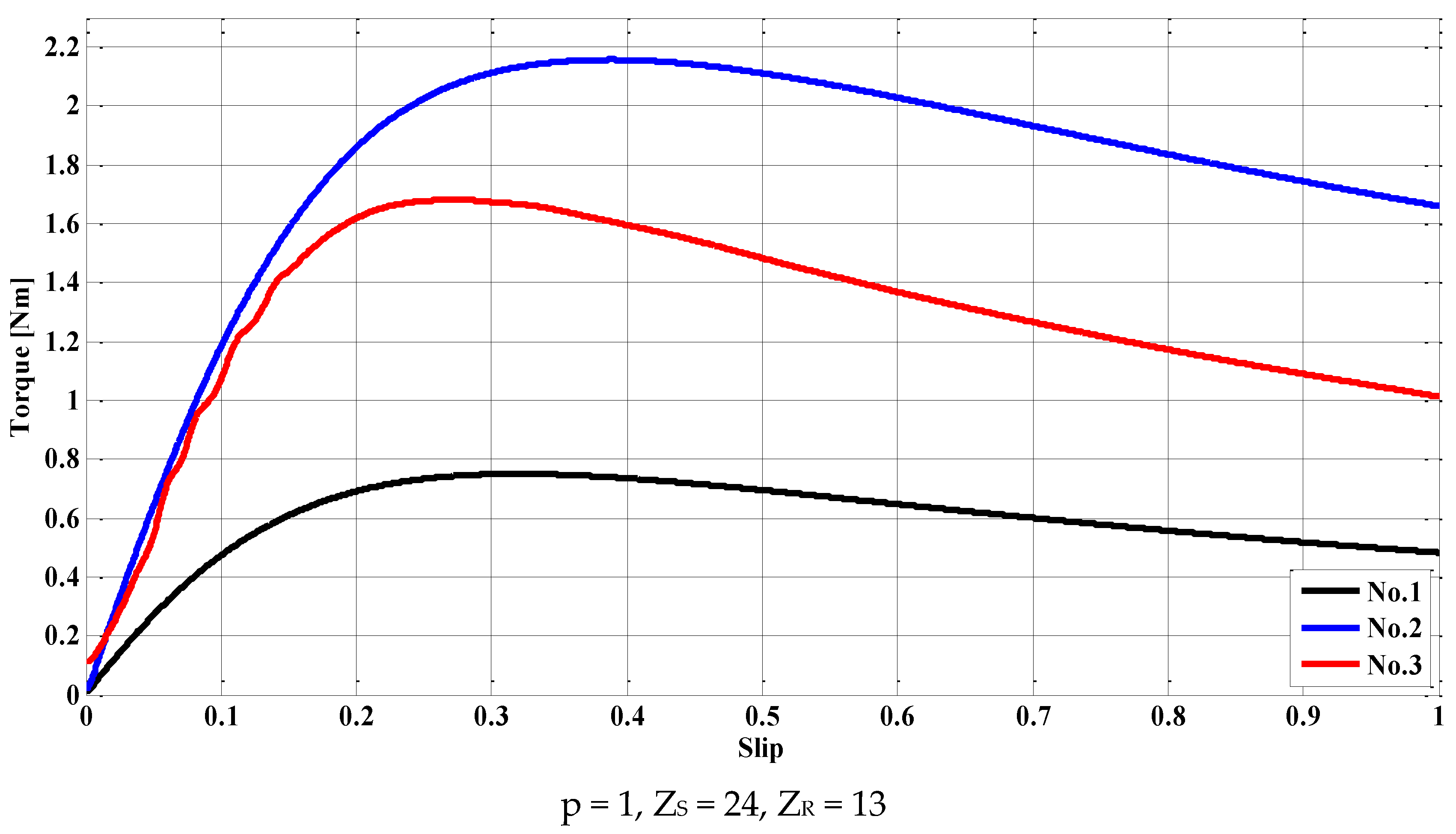
We found analytically that the optimum pole configuration was 2p = 4; however, to cover a larger design space exploration, 1, 2, and 3 pole pairs p were considered. As the diameter of such a small power machine imposed by this application is below 100 mm, the number of stator slots, ZS, should be below 30 for technological reasons, otherwise the stator tooth would be too narrow. Hence, for p = 1, the q number (number of slots per pole and phase) is 4, and, for p = 2, we have q = 2. Both topologies have 24 stator slots. For p = 3, technological limitations will provide q = 1, and, consequently, the stator will have only 18 slots.
The choice of the number of rotor bars, ZR, is at the liberty of the designer, as there are very few recommendations for this particular number of stator slots. First, the IM with p = 2 was designed. After the design process, three models, with 13, 14, and 17 numbers of rotor bars, were considered for numerical computation due to the obtained results. The IM with 16 rotor bars revealed an exaggerated ripple torque; therefore, it was not considered for further analysis. For this reason, the structures with p = 1 and 3 have 13 rotor bars. In addition to these models, an IM with p = 3 with 26 rotor bars was designed.
Six initial topologies of IM were designed using the conventional design procedure for the IM, under the constraints imposed by the application, according to [16], three for p = 2, two for p = 3, and one for p = 1. Successively, for each topology, the inner diameter (ID) was first decreased and then increased. Consequently, the outer diameter (OD) was modified, while the diameter of the shaft (DS), was kept constant for the same variant of each machine. In order to have the same number of turns, Nt, the active length (L) of the machines was modified accordingly.
In Table 3 the most important parameters (p, Nt, ID, OD, DS, L, masses of the iron core MFe, stator copper MCu, and rotor aluminum MAl and total mass Mt) of the best 18 obtained topologies are presented. The masses of each active part were totaled in order to make a fair comparison between the analyzed structures from the point of view of power density. The initial value of the air gap, g, was the same for all the designed IMs. The value of the eccentricity e was the same, 0 in all cases. For each structure, the fill factor had the same value, 0.4, regardless of the number of slots.
Table 3.
Parameters of the initially designed IMs (e = 0).
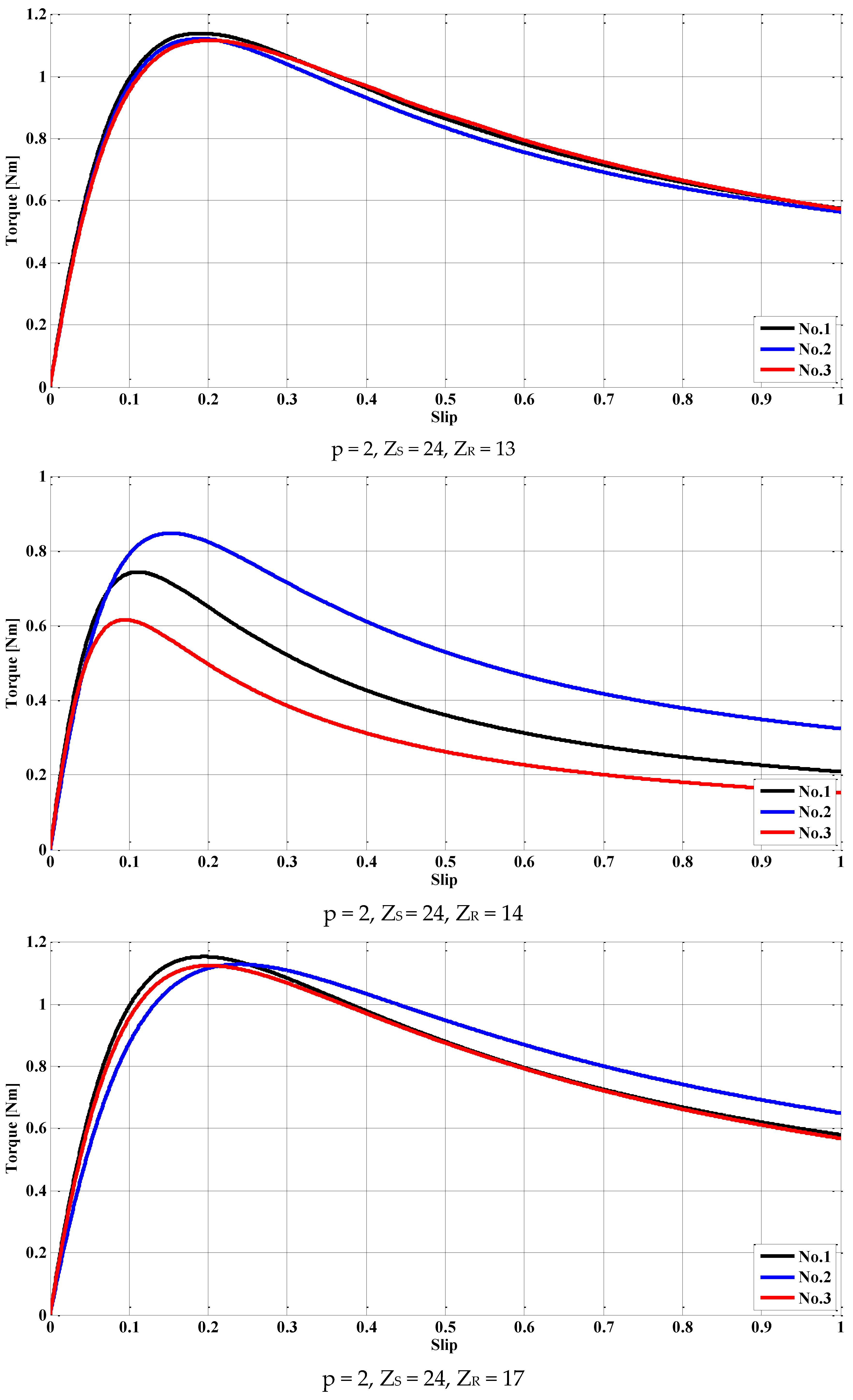
For all 18 models, the mechanical characteristics of torque vs. slip M = f(s) were obtained from FEM-based numerical computations using Flux 2D in a steady-state regime for frequencies corresponding to a synchronous speed of 3000 rpm, a function of number of pole pairs (as this speed corresponds to the maximum power of the IM). The characteristics for the best result of each combination (number of pole pairs, stator slots, and rotor bars) are presented in Figure 6. They have a twofold purpose: to demonstrate that the desired torque of the machine can be obtained and to choose the best variant from the point of view of the maximum developed torque.
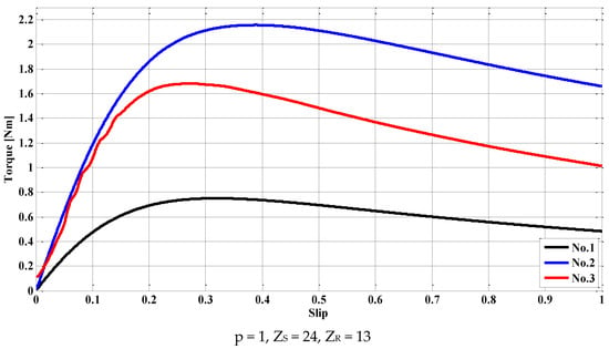
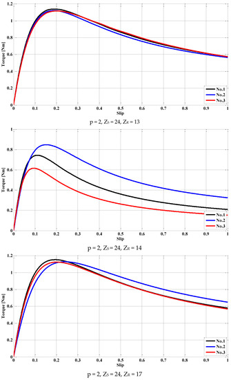
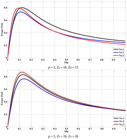
Figure 6.
Mechanical characteristics torque vs. slip of the IMs for ns = 3000 rpm.
3. Numerical Analysis of ZAIM
Based on the previous simulations, the best variant for each topology was adopted. For these conventional IMs, we applied different eccentricities. These values of 0.5, 1, and 1.5 mm corresponded to maximum values of air-gaps of 1, 2, and 3, respectively (the outer rotor diameter was decreased accordingly). In this way, an eccentric IM was obtained, which is denominated as a zero air-gap induction machine (ZAIM) due to the fact that the rotor touches the stator at one point.
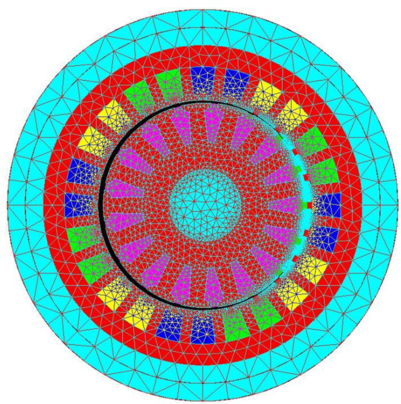
The characteristics of the IMs were computed in Flux 2D in a steady-state regime. As the numerical analysis software Flux 2D does not allow the superposition of two points, the minimum airgap between the stator and rotor was 0.01 mm. The following information regarding the mesh was extracted from the software: the number of excellent quality elements: 94.36%, the number of good quality elements: 4.53%, the number of average quality elements: 1.09%, the number of poor quality elements: 0.01%, the number of nodes: 24,373, the number of line elements: 3153, the number of surface elements: 12,154, and mesh order: second order. These values of the mesh assure good accuracy of the results. The meshed model of one of the analyzed ZAIMs is presented in Figure 7.
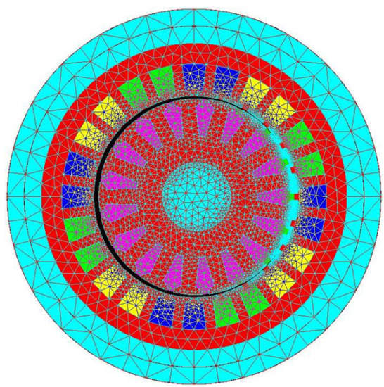
Figure 7.
Mesh of an analyzed ZAIM.
The numerical analysis presented below was performed at a frequency of 50 Hz and a speed of the rotor of 1425 rpm (slip of 0.04) to prove that the ZAIM can reach the corresponding operating point from Figure 2.
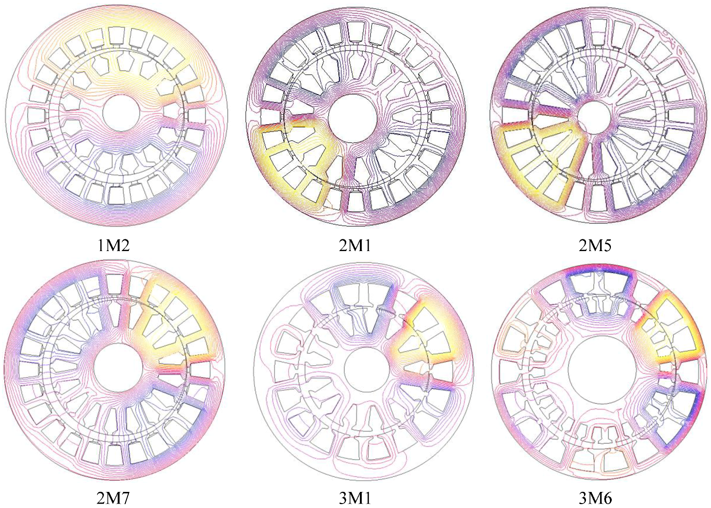
In the first step of the analysis, the flux density map and flux lines map were obtained to evaluate the saturation of the stator and rotor core and to obtain the flux lines route. Figure 8 shows the distribution of the flux density in the iron core of the ZAIMs with maximum eccentricity, 1.5 mm. The maximum value of the magnetic flux density was set at 2 T for all structures. In Figure 9, the flux lines in the iron core of the ZAIMs with maximum eccentricity are presented.
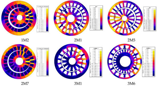
Figure 8.
Flux density in the iron core of the ZAIMs with e = 1.5 mm.

Figure 9.
Flux lines in the iron core of the ZAIMs with e = 1.5 mm.
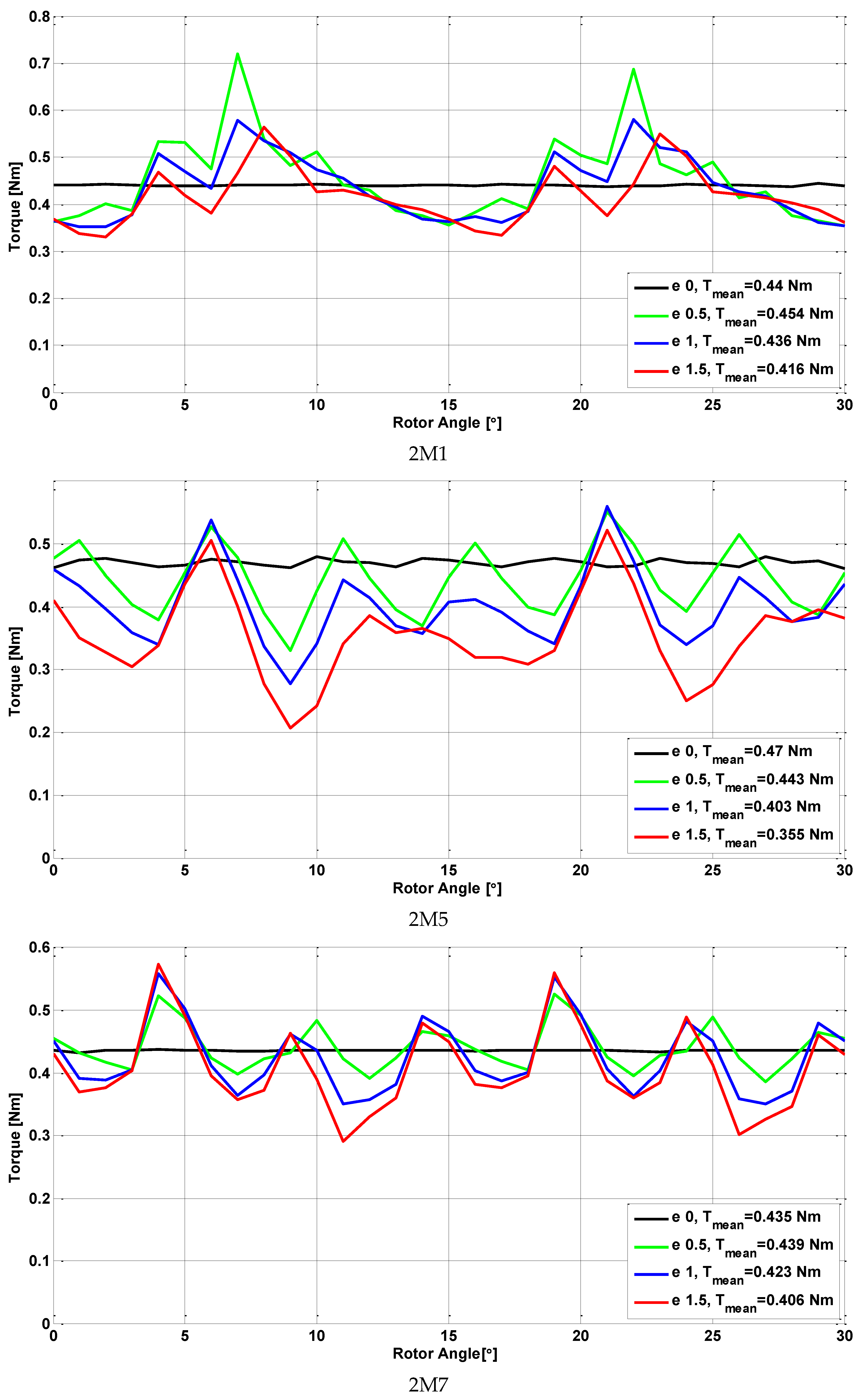
In the second step of the analysis, the torque vs. the position of the rotor for different values of the eccentricity were obtained as shown in Figure 10.
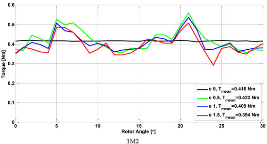
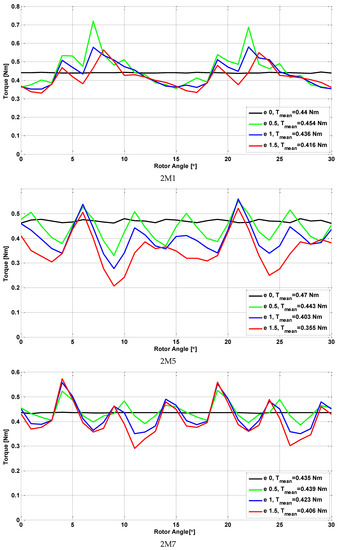
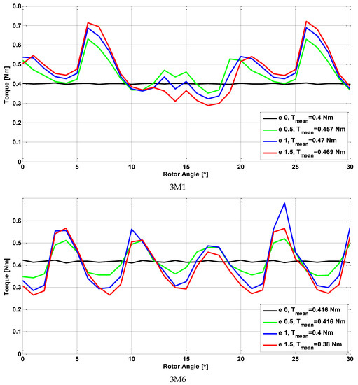
Figure 10.
Torque vs. position for all the considered ZAIMs.
The torque due to the friction that arises between the stator and the rotor can be obtained by computing the normal force between the two armatures. Given the dimensions of the ZAIM, the maximum values were 0.0011 N∙m at 1425 rpm and 0.005 N∙m at 3000 rpm; therefore, these very small values did not influence the developed torque of the ZAIM.
Via numerical analysis, we calculated, and summarized in Table 4, the mean value of the torque Tmean, the torque ripple values Tripple, the rms value of the stator current IN, the stator current density JS, the efficiency η, and the power factor cos φ for the best variant for each topology.
Table 4.
Parameters of the best model for each topology for various values of the eccentricity.
As the data show, the 3M1 model exhibited a greater torque at the considered eccentricities than the original IM. However, all the other output values were considerably poorer with the increase of the eccentricity. The best model from the point of view of the rated torque and torque ripples, rated current density, efficiency, and power factor appears to be 2M7, with e = 0.5 mm.
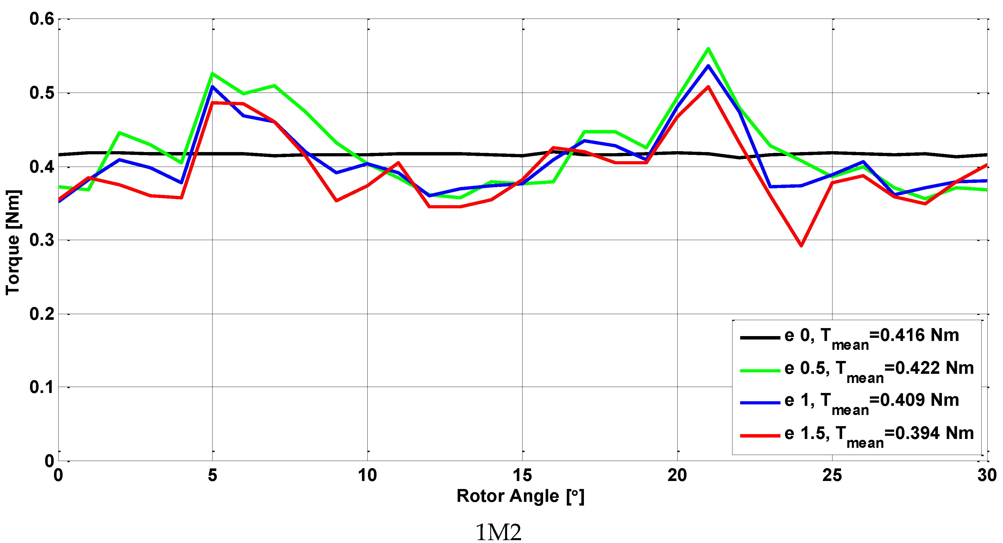
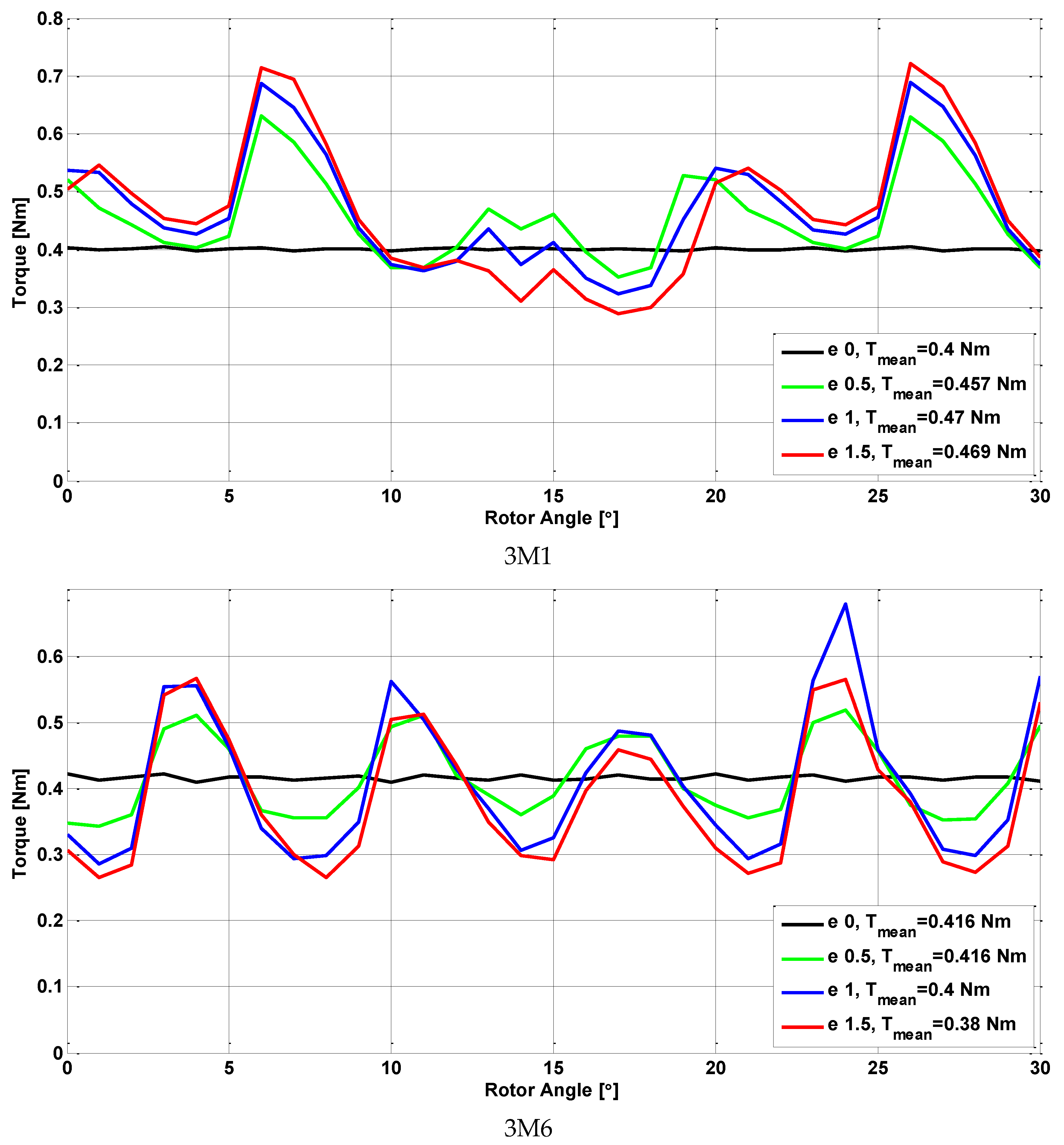
To obtain a more sensitive analysis of the influence of the eccentricity on the performance of the ZAIM, for the best topology of 2M7, we considered a more discrete step of the eccentricity. The results are presented in Figure 11.
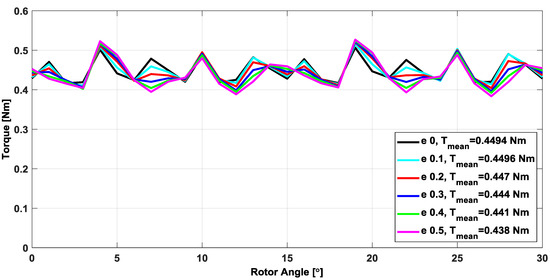
Figure 11.
Torques vs. position for the best variant of ZAIM.
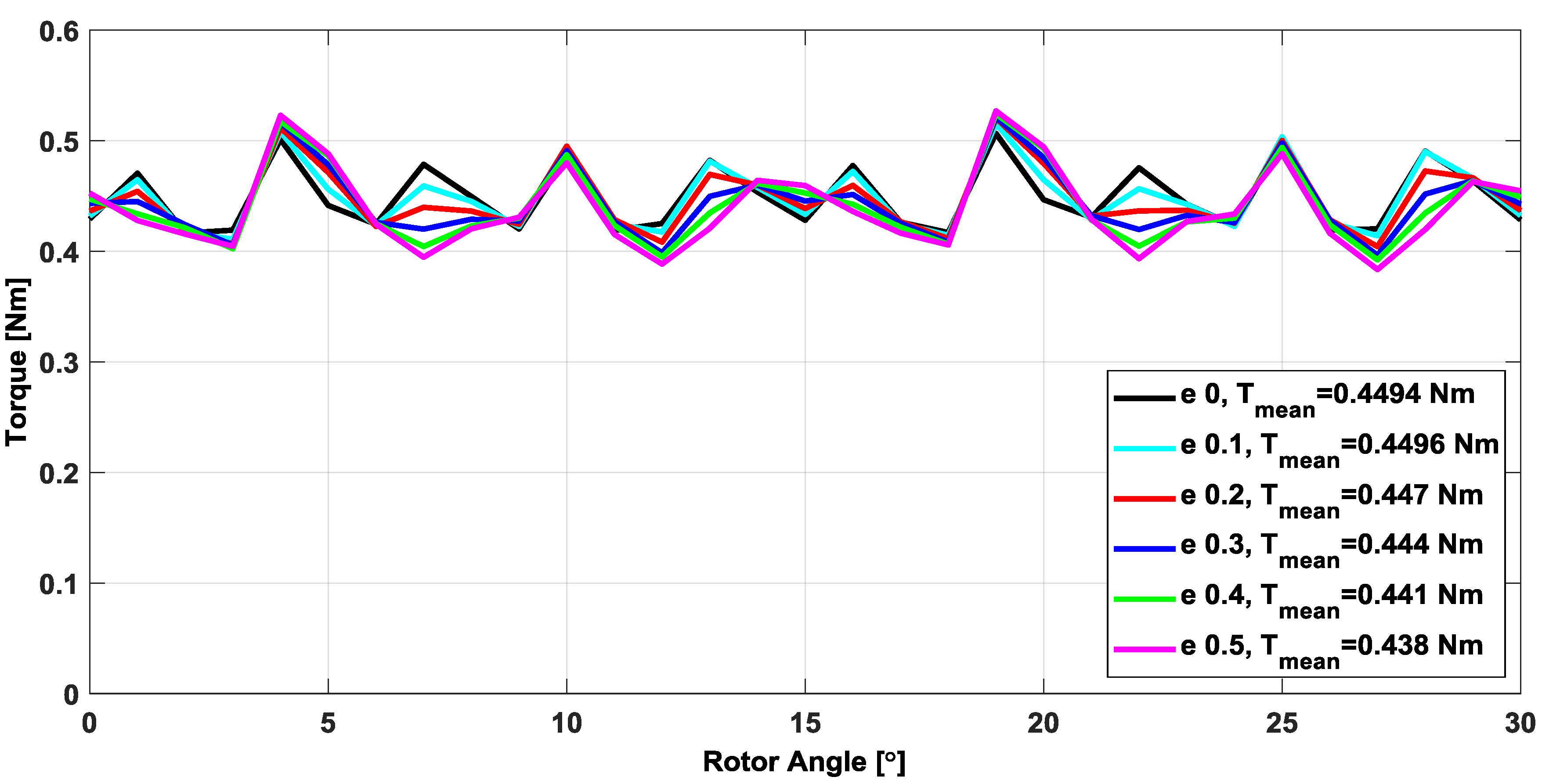
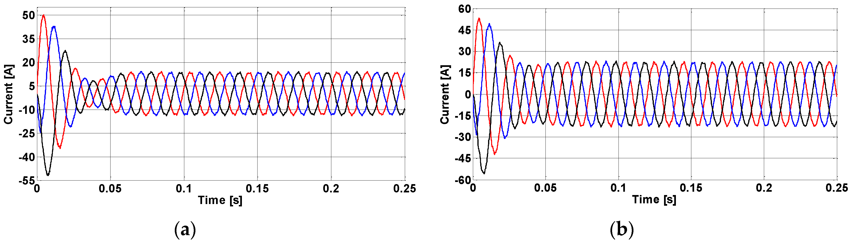
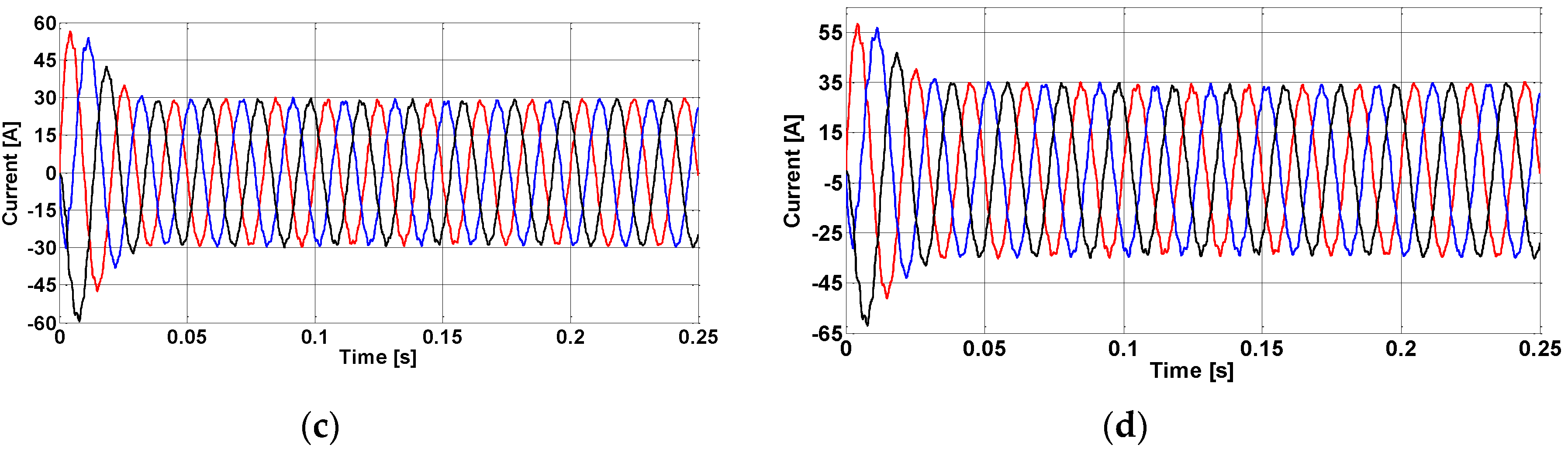
This structure was analyzed in the transient regime, using coupled circuit and supply both from the voltage and current source. Similar results are obtained in both cases. The step of the simulation was 1.17 × 10⁻⁴ s, corresponding to a step of the rotor of 1 degree. The variation of the torque and the currents, respectively, vs. time in the starting process of the ZAIM for different values of the eccentricity are presented in Figure 12 and Figure 13, respectively. The obtained results are in good accordance with those obtained in the steady-state regime. The variation of the torque vs. the eccentricity is presented in Figure 14.
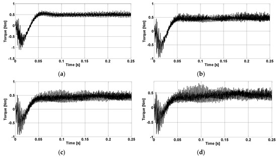
Figure 12.
Variation of the torque vs. time in the starting process of the ZAIM for different values of the eccentricity: (a) e = 0 mm; (b) e = 0.5 mm; (c) e = 1 mm; (d) e = 1.5 mm.

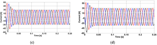
Figure 13.
Variation of the currents on the three phases vs. time in the starting process of the ZAIM for different values of the eccentricity: (a) e = 0 mm; (b) e = 0.5 mm; (c) e = 1 mm; (d) e = 1.5 mm.
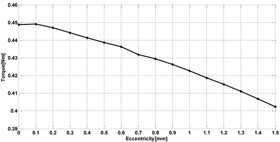
Figure 14.
Torque vs. eccentricity for the best variant of ZAIM.
The obtained results show that the values of the torque vary very little with the increase in the eccentricity. However, the toque ripples are higher and the power factor decreases with the increase in the eccentricity. For a small power machine, a low power factor could be compensated by the lack of mechanical unit if an eccentric motor is used.
An important aspect in the operation of the ZAIM is the thermal one. As both the analytic and numerical thermal analysis are complex, the most important parameter in this matter is the stator current density JS. As mentioned in Section 2, after the numerical analysis, its exact values are obtained, as shown in Table 4. These show that, for the conventional IM, the values of the current density are even below the values used for the conventional IMs with natural cooling, but even with the increase in the eccentricity they do not exceed the prescriptions for a machine immersed in ATF [16]. In these conditions, relatively normal values of temperature should be expected.
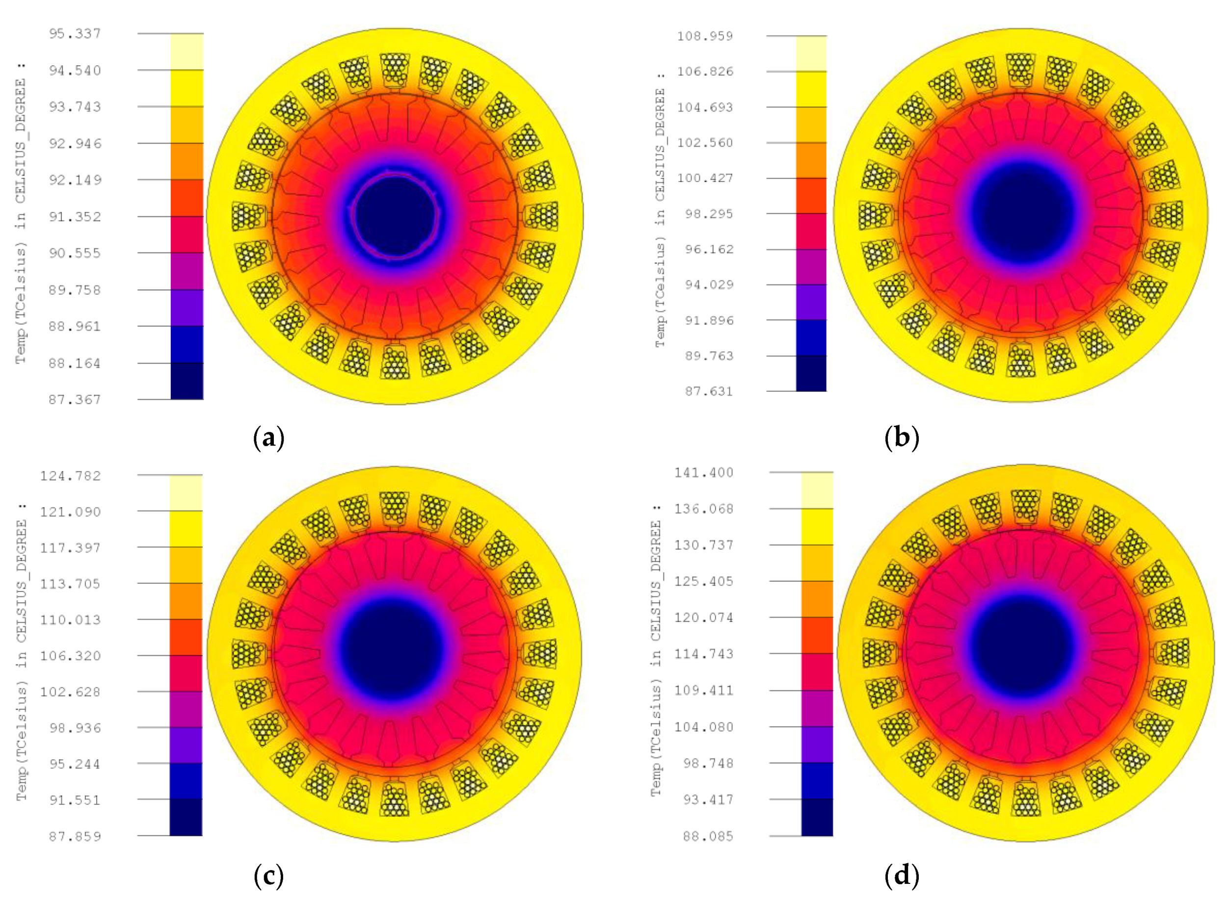
In order to obtain an evaluation of the thermal phenomena that occur both in the conventional IM and in the eccentric IMs, we performed a thermal analysis in the steady-state regime. This analysis offers only a general image of the thermal stresses that occur as it is performed in the most severe conditions possible. The motor was considered to operate in the steady-state regime at the rated current, which is not the actual operating regime of the IM, but corresponds to the maximum thermal stress, as shown in Figure 2. The heat transfer coefficient of oil was considered also at its lowest value, 50 W/m2∙K, in order to obtain the maximum values of temperature that could appear. The results are presented in Figure 15.

Figure 15.
Thermal analysis of the ZAIM in the steady state regime for different values of the eccentricity: (a) e = 0 mm; (b) e = 0.5 mm; (c) e = 1 mm; (d) e = 1.5 mm.
4. Conclusions
In this paper, we analyzed the use of a small power eccentric induction machine for the driving of a transmission oil pump. We designed and analyzed 18 topologies of IMs, with different numbers of poles pairs, stator slots, rotor bars, and geometrical dimensions. For the best model of IM with the same number of pole pairs and rotor bars, different values of eccentricities were considered. The numerical analysis was focused on obtaining the variation of the torque vs. position and the flux density map in the iron core of the machines. The results are given both in graphical form and in tables. In most cases, the mean value of the torque of the ZAIM decreased very little with the eccentricity. For all the topologies, the current and the torque ripples increased with the eccentricity. The efficiency and the power factor decreased with the eccentricity in all cases, strongly for greater eccentricities. However, when analyzing all these results, it must be considered that the ZAIM to be used for this application had a small rated power, and the dynamic behavior of the motor strongly depended on the existing hydraulic load. The thermal analysis performed in extreme conditions showed the acceptable temperatures for a machine without permanent magnets.
This comparison is the first step in the evaluation of using an eccentric induction machine for the driving of a transmission oil pump.
Author Contributions
Conceptualization, C.G.C., N.H., J.H., D.-C.P.; Resources, N.H., J.H.; Investigation, N.-F.J., R.A.I., D.-C.P.; supervision, C.G.C., D.-C.P., Writing—review and editing, D.-C.P., N.-F.J. All authors have read and agreed to the published version of the manuscript.
Funding
This research was funded by the Schaeffler Group USA, Inc LuK Transmission System LLC, and Ohio State University. This research was partially funded by a grant of the Romanian Ministry of Research and Innovation, CCCDI-UEFISCDI, project number PN-III-P1-1.2-PCCDI-2017-0776/No. 36 PCCDI/15.03.2018, within PNCDI III.
Conflicts of Interest
The authors declare no conflict of interest.
References
- Zhang, Q.; Li, M.; Cai, G. Research on the oil supply system of a vehicles integrated transmission based on LabView. In Proceedings of the 3rd Information Technology, Networking, Electronic and Automation Control Conference (ITNEC), Chengdu, China, 15–17 March 2019. [Google Scholar]
- Wi, J.; Kim, H.; Yoo, J.; Son, H.; Kim, H.; Kim, B. Energy Consumption of parallel type hybrid electric vehicles with continuously variable transmission using electric oil pump. In Proceedings of the Thirteenth International Conference on Ecological Vehicles and Renewable Energies (EVER), Monte-Carlo, Monaco, 10–12 April 2018. [Google Scholar]
- Kim, Y.; Lee, J.; Jo, C.; Kim, Y.; Song, M.; Kim, J.; Kim, H. Development and control of an electric oil pump for transmission-based hybrid electric vehicles. IEEE Trans. Veh. Technol. 2011, 60, 1981–1990. [Google Scholar] [CrossRef]
- Zhang, W.; Wang, B.; Zhang, Y.; Peng, L.; Liu, M.; Lv, Y. Research on modelling and simulation of a new variable displacement oil pump. J. Eng. 2019, 2019, 350–354. [Google Scholar] [CrossRef]
- Kuang, M.; Zhu, J. High-efficiency control strategy of Aeronautical fuel pump motor. In Proceedings of the Chinese Automation Congress, Changsha, China, 7–8 November 2013. [Google Scholar]
- Liu, Y.; Zhou, Y.; Wang, J.; Qu, D.; Zhang, F. Hydraulic system control for a hybrid continuously variable transmission based on an electric oil pump. IEEE Trans. Veh. Technol. 2018, 67, 10398–10410. [Google Scholar] [CrossRef]
- Liu, Y.; Zhou, Y.; Qu, D.; Zhang, F.; Bao, X. Electric oil pump design of hybrid continuously variable transmission. IET Electr. Power Appl. 2019, 13, 1089–1096. [Google Scholar] [CrossRef]
- Pop, A.C.; Gyselinck, J.J.C.; Pinto, D.E.; Vintiloiu, I. Optimization of Low-Power Brushless PM-Machines for Automotive Applications with Focus on High-Volume Mass Production. IEEE Trans. Ind. Electron. 2017, 64, 9767–9775. [Google Scholar] [CrossRef]
- Nandi, S.; Bharadwaj, R.M.; Toliyat, H.A. Performance analysis of a three-phase induction motor under mixed eccentricity condition. IEEE Trans. Energy Convers. 2002, 17, 392–399. [Google Scholar] [CrossRef]
- Ghoggal, A.; Hamida, A.H. Transient and steady-state modelling of healthy and eccentric induction motors considering the main and third harmonic saturation factors. IET Electr. Power Appl. 2019, 13, 901–913. [Google Scholar] [CrossRef]
- Bindu, G.R.; Basheer, J. A Novel Control Scheme to Mitigate Unbalanced Magnetic Pull due to Eccentric Rotor in Three Phase Induction Motors. In Proceedings of the International Symposium on Power Electronics, Electrical Drives, Automation and Motion (SPEEDAM), Amalfi, Italy, 20–22 June 2018. [Google Scholar]
- Smith, A.C.; Dorrell, D.G. Calculation of unbalanced magnetic pull in small cage induction motors with skewed rotors and dynamic rotor eccentricity, Part 1: Analytical model. IEEE Trans. Energy Convers. 1996, 143, 483–488. [Google Scholar]
- Alibeik, M.; Nezamuddin, O.; Rubin, M.; Wheeler, N.; Silvestri, S.; dos Santos, E. Airgap-less Electric Motor: A Solution for High-Torque Low-Speed Applications. In Proceedings of the IEEE International Electric Machines and Drives Conference (IEMDC), Miami, FL, USA, 21–24 May 2017. [Google Scholar]
- Alibeik, M.; Nezamuddin, O.; Rubin, M.; Wheeler, N.; Silvestri, S.; dos Santos, E. Airgapless Electric Motors with an External Rotor. IEEE Trans. Ind. Electron. 2018, 65, 6923–6935. [Google Scholar] [CrossRef]
- Lacour, G. Motor with Eccentric Rotor. U.S. Patent No. 2011/0121669 A1, 26 May 2011. [Google Scholar]
- Boldea, I.; Nasar, S.A. The Induction Machines Design Handbook, 2nd ed.; CRC Press: Boca Raton, FL, USA, 2009. [Google Scholar]
- Knight, R.D. Physics for Scientists and Engineers: A Strategic Approach with Modern Physics; Pearson: New York, NY, USA, 2016. [Google Scholar]


© 2020 by the authors. Licensee MDPI, Basel, Switzerland. This article is an open access article distributed under the terms and conditions of the Creative Commons Attribution (CC BY) license (http://creativecommons.org/licenses/by/4.0/).