Abstract
CubeSats and small satellite solutions are increasing in popularity as they enable a fast, cheap, and agile way for satellite applications. An essential component of nearly every satellite is the energy storage device, which is practically equal to a battery. Consequently, an overview of past, present, and future battery technologies for CubeSats is presented. CubeSats use typically commercial off-the-shelf (COTS) batteries. They are not primarily dedicated to space, so their suitability to the space environment needs to be evaluated. Batteries are also considered as potentially dangerous goods. Thus, there are guidelines and standards that specify safety criteria and tests for the batteries in order to be allowed for transportation and launch. Furthermore, the character of satellites’ missions determines their demand on batteries in terms of current rates, depth-of-discharge, and lifetime. Thus, these expectations are discussed. A market survey was also carried out to identify currently available commercial battery solutions and their parameters. This work summarizes the status, requirements, and the market situation of batteries for CubeSats.
Keywords:
battery; battery pack; CubeSat; electrical power supply; lithium-ion; market; qualification; requirement; satellite; standard 1. Introduction
The NewSpace trend promotes the commercialization of space and favors faster and cheaper solutions. This has resulted in an increasingly popular branch of satellites which tend to be smaller. The recognized categories of ‘light’ satellite solutions, according to their weight, are pico-satellites: <1 kg, nano-satellites: 1–10 kg and micro-satellites: 10–100 kg. A special category is CubeSats. The CubeSats are composed of standardized 10 × 10 × 10 cm cubes, where one cube is described as 1U [1]. A satellite can be constructed from several of such cubes to reach typically a 1–16U spacecraft. Thus, the CubeSats are considered to be nano- or, in their lower range, micro-satellites, which are going to be referred to in this manuscript as small satellite solutions, as often used in the industry sphere [2,3]. The CubeSat platform has two great advantages which directly impact the cost. Firstly, the fixed size and shape allow for launcher requirement standardization. Secondly, the developed CubeSat components fit exactly to the structure and this combatability opens them up to the wider market [4]. Another aspect of the NewSpace and CubeSat approach that brings the cost down is the utilization of so-called commercial off-the-shelf (COTS) components. This practically means that, instead of using space dedicated expensive components, ordinary components for terrestrial applications are used, after they qualify for the space environment. So far, over 1200 CubeSats/nano-satellites have been launched [5] and the number of launches is projected to be around 300 in 2020, with a growing trend every year [6]. Moreover, a distinguishing feature of the CubeSat scene is that not only large nations are constructing and operating the satellites, but now it is also feasible and done by small nations, companies, and even public institutions, such as universities, where these activities are carried out by students [7]. In order to ensure global coverage for services, satellites are deployed in groups, forming constellations. Moreover, 26 constellations were identified by A. Camps [8] and summarized in terms of their size, form factor of satellites, and mission type. An example of existing CubeSat and Small Satellite missions is provided in Table 1.

Table 1.
List of a few well-known CubeSat missions and small satellite projects, adapted from [9], licensed under CC BY 4.0.
In order to accomplish its mission, every satellite needs an electrical power supply to feed the rest of the satellite bus and a payload. The power flow is controlled by an electronic power system (EPS) which coordinates the flow between generation and storage units and the payload. Typically, in the CubeSats, solar panels take the role of power generation and secondary batteries serve as energy storage. Even though some exceptions can be found, such as nano-satellites without solar panels, running only on primary batteries, or even one nano-satellite without any battery, they are very marginal cases [10]. The task of the battery is to provide power when the production from solar panels is not sufficient to cover the consumption. This is especially the case when a satellite passes through an eclipse and there is no light reaching the solar panels. If the battery is not able to fulfill this requirement, it can lead to an interruption of the mission, or even to a loss of the spacecraft. Thus, the battery is a very important component in satellites and it is necessary to ensure its reliable operation in the space with a sufficiently long lifetime.
This review provides an overview of battery technology used in CubeSats, its requirements and market status.
2. Battery Types for Small Satellites
The selection of batteries for satellites is driven by multiple factors, such as, but not limited to, peak power requirements, the worst-case orbit energy requirement, operating temperature, and mission life [11]. At first, a suitable cell type is selected according to these requirements. Then, the combinations of the cells are used to form a battery pack, which must fulfill all the target criteria.
2.1. Primary Batteries
Primary (non-rechargeable) batteries are used in cases when they are necessary only for one-time short use, e.g., during launch or shortly after launch, or for extended periods of very small power consumption. Their advantages compared to secondary batteries are typically higher volumetric and gravimetric energy density or power density and wider operating temperature range. A high gravimetric power density can be offered for example by Ag-Zn cells with 1100 W/kg, but due to their fast capacity loss (60%/year), they are suitable only for very early use. Other candidates can be Li-SO2 cells with 680 W/kg and a wide temperature range between −40 and 70 °C, though with a smaller energy density (238 Wh/kg, 375 Wh/l). The high energy density can be provided by Li-BCx and Li-CFx systems with 414 Wh/kg, 930 Wh/l and 614 Wh/kg, or 1050 Wh/l, but their limitation is a low specific power of 150 W/kg and 15 W/kg, respectively. Thus, Lithium-based batteries have become the preferred choice [10,11].
2.2. Secondary Batteries
Secondary batteries are much more used than the primary batteries in CubeSats, as most of the missions have an orbital character and the cumulative energy demand over a satellite’s lifetime is much higher than the primary batteries can deliver. A survey made by J. Bouwmeester in 2010, illustrated in Figure 1a, shows the representation of the secondary battery chemistries used in nano-satellites: 66% Lithium-ion (Li-ion), 16% Nickel-Cadmium (Ni-Cd), 12% Lithium-polymer (Li-pol), 4% Lithium-Chloride (Li-Cl), and 2% none [10]. Since then, Nickel-metal hydride (Ni-MH) batteries were used also in the Horyu-4 satellite, manufactured in 2013–2014. Otherwise, the selection is completely ruled by Lithium-based batteries due to their significantly higher (2–3×) energy and power densities than for Ni-Cd and Ni-MH systems [12,13,14].
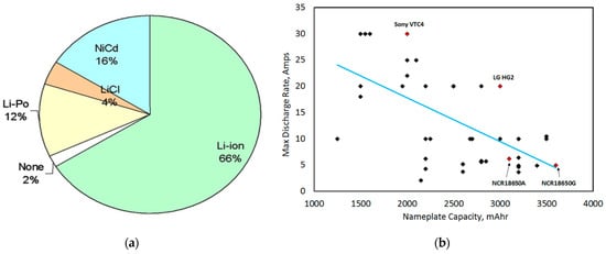
Figure 1.
(a) Battery types used in pico- and nano-satellites until 2010 according to [10]. Reprinted from Acta Astronautica, Vol. 67, J. Bouwmeester, J. Guo, Survey of worldwide pico- and nanosatellite missions, distributions and subsystem technology, pp. 854–862, Copyright (2010), with permission from Elsevier; (b) Summary of maximum discharge rate capabilities versus nameplate capacity of some representative COTS 18650 Li-ion cells. Types of COTS battery cells [15]. Reprinted from Proceedings of the IEEE, Vol. 106, K.B. Chin et al., Energy Storage Technologies for Small Satellite Applications, pp. 419–428, Copyright (2018), with permission from IEEE.
Cylindrical 18650 (18 mm diameter and 65 mm height) COTS cells are widely used for CubeSats, due to their suitable size and generally good tolerance for the space environment. Li-ion battery family covers multiple chemistries, in this case, their anode is typically graphite or other carbon-based materials. The cells and their characteristics differ based on the cathode materials, which are qualitatively summarized in Table 2. Chin et al. summarized in [15] representative 18650 COTS cells according to their maximum discharge rate capability and nominal capacity, as presented in Figure 1b. The performance of the cells can be considered bound by three specific cells: Sony VTC4, LG HG2, and Panasonic NCR18650G.
Table 2.
Overview of the commercially available 18,650 Li-ion cell chemistries and their qualitative characteristics [15]. Reprinted from Proceedings of the IEEE, Vol. 106, K.B. Chin et al., Energy Storage Technologies for Small Satellite Applications, pp. 419–428, Copyright (2018), with permission from IEEE.
Li-pol cells are traditionally having a pouch format. This provides them the benefit of flexible size, slim profile, and generally reduced weight. However, due to the mechanical attributes, they might be prone to damage in the space environment (vacuum) if not carefully constructed. A bulging problem of pouch cells was solved by potting them with polyurethane and epoxy resin to avoid swelling in vacuum [16]. The characterization of commercial Li-pol cells from two manufacturers was performed in [14], whereby the cells from one manufacturer lost significant capacity in vacuum while the cells from the other manufacturer withstood the stress without any problems.
Prismatic cells with suitable size for CubeSats are available too [17]. Besides terrestrial dedicated batteries, the space dedicated batteries of smaller formats can be found, e.g., supplied by SAFT [18].
Several trends were identified for improving batteries for nano-satellites. The capacity of 18,650 cells is incrementally improving, the cells with the maximum capacity reaching 3500–3600 mAh are currently available on the market [19]. Considering an approximate cell weight of 50 g and an average voltage of 3.6 V, the current solutions offer an energy density of 252 Wh/kg and 762 Wh/l.
One of the challenges for space applications is the low-temperature operation. On the orbit, the spacecraft surface experiences extreme temperature fluctuations, which can reach up to ±100 °C [20]. In the case of a low thermal mass and low heat generation, the batteries can be exposed to subzero temperatures. A low temperature is also expected at satellites dedicated to exploratory missions in deep space. In these cases of subzero temperatures, a reduction of useable capacity during discharging and rapid degradation of the cells during charging are expected. General limits for Li-ion batteries, often stated in datasheets, are charging down to 0 °C, discharging to −20 °C. Gave et al. introduced cells, being able to discharge at −40 °C with 100 Wh/kg and repetitive charging at −20 °C [21]. Farmakis et al. demonstrated cells being able to cycle at −40 °C with 140 Wh/kg [22]. Chin et al. accommodated an alternative approach when at first a classical Li-ion cell was enhanced with a developed low-temperature electrolyte, which ensured 71% capacity retention at −40 °C [23]. Especially, they introduced super-capacitors to form a hybrid energy system. At low temperatures, the Li-ion batteries’ internal resistance is rapidly increased, causing a major voltage drop that limits the discharge by reaching the battery minimum voltage very quickly. The super-capacitors have lower resistance than Li-ion batteries and they are suitable for high currents. Thus, in a hybrid system, the super-capacitors significantly reduce the voltage drop when high currents are drawn, especially at low temperatures, and thereby the system’s performance is highly improved. The dependence of the resistance on the temperature according to the mentioned technology is presented in Figure 2.
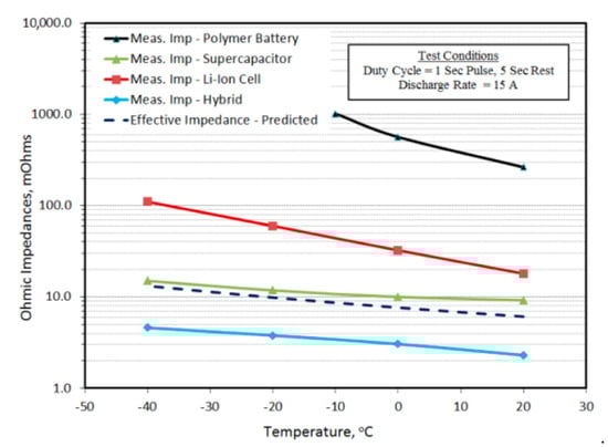
Figure 2.
Summary of ohmic resistance of all energy storage systems from ground testing [23]. Reprinted from Proceedings of the AIAA/USU Conference on Small Satellites, K.B. Chin et al., Li-ion battery and super-capacitor Hybrid energy system for low-temperature SmallSat applications Conference on Small Satellites, with permission from the authors.
Another technology, which combines capacitors and Li-ion batteries are Li-ion capacitors. They are hybrid energy-storage devices, that combine ions sorption by capacitor type electrode and Li-ion insertion and intercalation by a Li-ion battery type electrode [24]. Li-ion capacitors have significantly lower energy density than Li-ion batteries. However, they can operate over a wider temperature window, they have higher power capability (larger C-rates), and much longer lifetime. Akio and Shuhei [25] tested a Li-ion capacitor system in a satellite. The Li-ion capacitor cell specifications were 303 g weight, 125 × 165 × 15 mm size, pouch format, 1.171 Ah capacity, and 11.8 Wh/kg energy density. They identified that if the battery capacity is utilized only to 10% and less, Li-ion capacitors can be a competitive solution for the energy storage system.
Great attention is given also to the development of Lithium-Sulfur (Li-S) batteries. Li-S batteries have a theoretical gravimetric energy density six times higher than Li-ion batteries, which could potentially lead to smaller and especially lighter battery systems, which translates in the space industry to be significantly cheaper. At this moment, the technology is not commercially ready. The practically obtained energy density needs to be improved to be the preferred option for Li-ion batteries. Moreover, Li-S batteries suffer from fast degradation, high self-discharge at high state-of-charge levels, and limitations in power capability that needs to be addressed [26,27,28].
The solid-state battery technology represents another direction of the development. The promises of this technology are significantly improved energy densities, longer life, and enhanced safety. Moreover, solid-state technology could be further applied to Li-S batteries to take advantage of both their strong sides [29,30].
A concept of how to revolutionize the use of batteries in satellites, was presented by Lyman et al. [31]. A classical battery pack could be at least partially replaced by a structural energy storage. In this case, the battery is integrated into body parts of a satellite and by that utilizing some of the ‘dead weight’ for storing the energy.
3. Battery Suitability and Safety
The term ‘battery‘ is commonly used not-uniquely for a single cell and for a battery pack (multiple cells connected in series, parallel, or a combination of both). To keep a clear distinction between these two system levels, the following section uses the terms (battery) ‘cell’ and (battery) ‘pack’ to point out the clear difference at what level the tests are required. The cell level testing is typically focused on the electrochemical performance, lifetime, safety, and mechanical structure of a cell. A battery pack consists of a certain number of battery cells, it has typically a printed circuit board (PCB) with electronics, providing basic functionalities (e.g., electrical connection routing, safety, balancing, control etc.) and a mechanical structure that keeps it together. Thus, the battery pack level is more complex and it includes requirements also in terms of electronics to be used in space.
3.1. Suitability for Space Environment
COTS battery cells are the most popular to be used in CubeSats. However, they are not primarily dedicated to the space environment. Thus, tests, proving their suitability, must be conducted before the cells can be used in spacecrafts.
Radiation, vacuum, temperature, and vibrations can be considered as main factors of the space environment that can affect the batteries.
3.1.1. Space Radiation
The space environment contains energetic particles, such as electrons and ions, with energies in the range of MeV or higher [32]. These particles can cause damage to a spacecraft in terms of [33]:
- Total ionizing dose (TID): over time, it’s cumulative impact leads to a component degradation.
- Displacements damage dose (DDD): atoms can be knocked out of their original location.
- Single events effects (SEEs): causing upsets/latchups/transients in electronics.
- Deep dielectric charging: penetration of dielectrics by an energetic electron leading to a discharge, which damages circuits and materials.
Typically, shielding is used to reduce components exposure to this radiation. However, the shielding at CubeSats is very limited due to their size and weight restrictions [34]. Electronics COTS components were tested in [35] and it was shown that some of them were able to survive up to 20–30 krad. The amount of radiation effect in terms of TID, DDD, and SEE on small satellites was studied by Samwel et al. [36] for maximum and minimum solar activity. They considered a 3 years mission with polar sun-synchronous orbit at 800 km altitude and 98.5° inclination. In that condition, the total TID exposure without any shielding would be 3.73 Mrad, and with 1.5 mm aluminum shielding only 33.1 krad, during maximum solar activity. The amount of expected TID per year at reference orbits is illustrated in Figure 3.
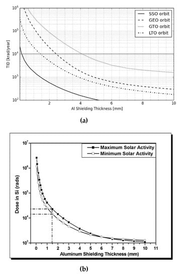
Figure 3.
(a) Total Ionizing Dose for four reference orbits in relation to thicknes of aluminum shielding [34]. Reprinted from Acta Astronautica, Vol. 131, D. Selčan et al., Nanosatellites in LEO and beyond: Advanced Radiation protection techniques for COTS-based spacecraft, pp. 131–144, Copyright (2016), with permission from Elsevier; (b) Total ionizing dose-depth curves for Si as the target material for a 3-year mission length during maximum and minimum solar activity for polar sun-synchronous orbit at 800 km altitude and 98.5° inclination [36]. Reprinted from Advances in Space Research, Vol. 64, S.W. Samwel et al., Space radiation impact on smallsats during maximum and minimum solar activity, pp. 239–251, Copyright (2019), with permission from Elsevier.
Related to Li-ion battery cells, the effect of neutron and gamma radiation on LiCoO2 cathode material was studied by Qiu et al. [37]. They identified an increasing grain size of the cathode material due to the irradiation. An 8.4% capacity loss was measured after 2.774 Mrad gamma irradiation; however, the radiation-induced electrolyte decomposition could be a contributing factor, which was not eliminated. Tan et al. [38] studied the effect of gamma radiation on the Li-ion battery electrolyte. The electrolyte kept its original color after 100 krad exposure, but after 700 krad and 2.7 Mrad it changed its color due to its decomposition. Another study, this time on both a cathode (LiFePO4) and electrolyte, was carried out by Tan’s group [39]. They revealed that both components contribute to the capacity loss after heavy radiation (26.7% loss at 9.8 Mrad of the irradiated cathode, 11.2% loss at 5.7 Mrad of the irradiated electrolyte), as shown in Figure 4c. However, regarding the cell’s resistance, the electrolyte shows high sensitivity and it increases gradually (Figure 4b), while at the cathode, a significant increase was detected only after 9.8 Mrad radiation, as presented in Figure 4a. Cells from five various manufactures were studied at radiation doses up to 25 Mrad [40,41]. Visible performance variances between radiated cells and control cells started from 1 to 3 Mrad. Thus, the lifetime of Li-ion battery cells is negatively affected by the radiation. However, the expected levels of TID for batteries in CubeSats at LEO are in the range of 10–30 krad [42]. In that case, using linear interpolation based on the previous studies, it can be expected that the radiation will contribute maximally only to 0.1% of capacity loss. Hence, it is considered generally negligible [11]. Nevertheless, the ESA Li-ion battery testing handbook [43] recommends performing radiation test for cell qualification. The total dose irradiation test [44] is still very relevant for battery packs since electronic parts are sensitive to the radiation [45].
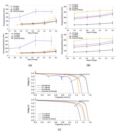
Figure 4.
Changes in cell resistance during charge (top) and discharge (bottom) as a function of (a) irradiation dose to the LiFePO4 cathode, and (b) irradiation dose to the electrolyte. (c) Discharge curve examples of batteries fabricated with irradiated cathode only (top) and irradiated electrolyte only (bottom) [39]. Reprinted from Journal of Power Sources, Vol. 318, C. Tan et al., Radiation effects on the electrode and electrolyte of a lithium-ion battery, pp. 242–250, Copyright (2016), with permission from Elsevier.
3.1.2. Vacuum
There are two aspects regarding batteries and vacuum. The first is related to the outgassing. Batteries, as any component going to the space vacuum environment and not being considered as ‘low-outgassing’, have to go through the process of a thermal bakeout (thermal vacuum) to trigger any possible sublimation or evaporation during the ground test. This is done in order to prevent outgassing material to contaminate sensitive components and by that to jeopardize the mission [46]. The test specifications are generally provided by the launch provider [1]. The specific test procedure can be found for example in the ESA standard ECSS-Q-ST-70-02C [47], where it is expected for the component to stay for 24 h at a pressure of 10−3 Pa (~7.5·10−6 torr, 10−5 mbar, 1.45·10−7 psi) and elevated temperature. The temperature is specified in the standard to be 125°C. However, for the battery cells, it has to be lower to not compromise their functionality.
The second aspect is focused directly on the functionality of batteries in vacuum. The cells can experience electrolyte leakage or swelling, in the case of pouch cells, just by being exposed to the vacuum [48]. A ‘leak’ test is then performed to assess the battery suitability. ECSS-E-HB-20-02A [43] specifies the leak test procedure followingly: The battery cells shall be outgassed first, then they are exposed to a vacuum of 10−6 mbar (~10−4 Pa, 7.5·10−7 torr, 1.45·10−8 psi). Then, a mass spectrometer or a pH paper shall be used to detect any possible leak. In JSC 66548 [48], the leak test is defined as a 6 h stay at 10−5 torr (~1.3·10−3 Pa, 1.3·10−5 mbar, 1.9·10−7 psi) for EVA environment, or 8–10 psi (~5.5−6.9·104 Pa, 414–517 torr, 552–690 mbar) for Li-ion polymer/pouch cells instead. There shall be (1) a visual inspection for any leaks and bulges, (2) weight check, with a change less than 0.1% in order to pass, (3) OCV check, with a change less than 0.1% in order to pass, and (4) capacity check, with a change less than 5%. Several 18650 COTS cells were evaluated in [49]. The mass change after the thermal vacuum was typically around ±0.005 g. One sample lost weight over 0.02 g and it was considered as having a not sufficiently robust seal. The cycling capability in vacuum shall be also assessed. Ten charging-discharging cycles at a pressure of 10−7 torr (~1.3·10−5 Pa, 1.3·10−7 mbar, 1.9·10−9 psi) were performed for two types of Li-pol cells in [14]. For one battery cell type, the discharge capacity in the vacuum was within 1% of the capacity value in the standard pressure, while the other battery cell type experienced 10% capacity reduction after the first cycle in the vacuum and after the second cycle, one cell even failed. Eleven cycles at room temperature and pressure about 10−3 Pa (~7.5·10−6 torr, 10−5 mbar, 1.45·10−7 psi) were considered in the testbed developed for evaluating COTS Li-ion batteries for nano-satellites in [50].
3.1.3. Temperature
According to ECSS-E-ST-10-03C [51], additioned by [52] for CubeSats, all space segment equipment shall be tested in vacuum for extreme temperatures (i.e., hot and cold case) and temperature rate of change. Eight thermal cycles shall be performed between maximum and minimum temperature limits. The temperature limit is considered as a qualification temperature value, which is the acceptance temperature extended by 5 °C towards harsher conditions. The vacuum test can be combined with the ambient test to reach the target number of cycles, but at least one thermal cycle has to be carried out in the vacuum.
3.1.4. Vibration and Shocks
Batteries are exposed to vibrations during the satellite launch which can impose a risk of internal short hazards in cells or mechanical damages in the battery packs. The specifics of the vibration test are determined typically by the launch provider (i.e., launcher/mission specific) [1]. NASA determines the vibration test as one minute vibrations with characteristics shown in Table 3 in each axis. The batteries shall then be evaluated with pass/fail criteria being 0.1% change in OCV and mass before and after the test, and 5% change in capacity [48].
Table 3.
Vibration test specifications according to JSC 66548 [48].
3.2. Safety Requirements and Flight Acceptance
Li-ion batteries are considered, by the UN, to be dangerous goods of class 9 [53]. They are electrochemical devices, which store a considerable large portion of energy and by its rapid release, often due to abuse or damage, they produce a large amount of heat. When the heat is not sufficiently dissipated, the battery temperature increases. When a temperature threshold is reached, the so-called ‘thermal runaway’ takes place. Thermal runaway is a heat-generating exothermic reaction, which propels itself and often ends in cell’s venting, rupture, explosion, or fire [54]. Therefore, safety regulations are imposed on Li-ion batteries to ensure their safety.
3.2.1. On-ground Handling and Transportation
As the first regulatory area, it can be considered on ground handling and transportation. Various standards are dealing with Li-ion batteries (e.g., UL 1642, UN 38.3, IEC 62281) and they were recently summarized by Carré and Ruiz [55]. They identified that even though, the type of tests are shared in some degree across the standards, their test procedures are not harmonized, asking for a different number of samples, test values, and limits, and to be performed at different levels (a single cell/ a battery pack/ a spacecraft). Thus, the situation is rather complex. The list of tests required according to the standards, as summarized in [55], is shown in Table 4.
Table 4.
Required safety tests per standard as summarized in [55].
3.2.2. Qualification and Flight Acceptance
The second regulatory area is flight acceptance. The battery pack, as a part of a spacecraft, in order to be deployed in space, needs to be compliant with launch and deployment providers. Each of them might have their specific requirements. One crucial factor is that if humans are involved in the process (e.g., crewed launch rocket, deployment from ISS), then the requirements are more strict. Generally, it is a good practice to follow standards and guidelines provided by space facilitating institutions, as provided for example in JSC 66548 [48], JSC 20793 [56] by NASA, or in ECSS-E-HB-20-02A by ESA [43]. Considering the before mentioned documents and cell selection methodology presented by ABSL [49], the battery cell/pack acceptance process can be illustrated as in Figure 5.

Figure 5.
Process for flight accepted battery cells/packs.
At the beginning of the process, the requirements for the battery pack have to be assessed. That incorporates typically considerations from launch/deployment providers, market demands, spacecraft design, and mission design. It can result in a need for specific dimensions, weight, energy storage capability, power capability, lifetime, safety, and monitoring features. Thus, the battery pack requirements impose some requirements and expectations on battery cells, which shall be used in it. Currently, on the market, there are many battery cell products from various manufacturers which can be potentially used in CubeSats. The first step, according to [49], is to define specific criteria and then evaluate the market available cells against them “on paper”. Then, moving to the engineering test phase, a few best candidates are selected for the early test campaign, which shall assess their compliance in the space critical areas (e.g., vacuum, vibration). The engineering test phase is further used for evaluating the cells’ performance, lifetime, and safety in order to select the most promising candidates and to assess their suitability in close detail. In this phase, the battery pack functionalities and design are tested as well and adjustments can be done. The cells and packs used in engineering testing are considered unclassified and they do not have to have a quality assurance [48]. The expected tests to be performed on COTS Li-ion batteries according to NASA [48] is illustrated in Figure 6.
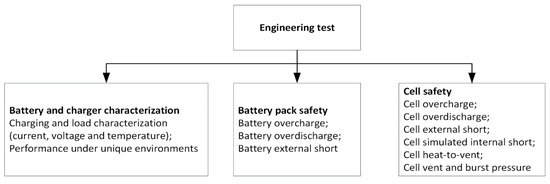
Figure 6.
The minimum number of tests to be performed on COTS Li-ion batteries for engineering evaluation according to and recreated from [48].
The qualification test is carried out on battery cells and packs, which are identical to ones, which will be used in the spacecraft. It is the most comprehensive testing that needs to be carefully documented and which certifies if the used technology is acceptable for flight. They are exposed to higher stress than the flight batteries and even abused (e.g., short circuit, overcharge), so they are not expected to be used for the flight.
Manufacturing differences can exist in battery cells between different lots and batches. Thus, to ensure the quality of the critical performance and safety, a lot acceptance test (LAT) is required. A defined sample needs to be selected from every new lot and undergo LAT. Generally, the LAT is less comprehensive than the qualification test, but it is also a destructive test. The LAT is performed typically only at the cell level. The detailed documentation is expected as well.
The flight acceptance test (FAT) is performed on all the flight batteries (cells and packs), without any exception and they cannot be further modified or compromised in any manner. FAT is used to ensure safety and avoid a risk of any detectable manufacturing defect. Due to the character of the FAT, it is not a destructive test and its detail documentation is needed.
The overview of the recommended tests according to [43] is presented in Table 5. However, not all the tests are described there in detail, for example, it is not explained what it is expected under ‘balancing system test’ for qualification and FAT at the battery cell level.
Table 5.
Applicability of the tests on Li-ion battery cells/packs [43]. Reprinted and edited Table 6-1 of ECSS-E-HB-20-02A “Space engineering—Li-ion battery testing handbook”, reproduced with permission of ESA.
3.2.3. Passivation
The last important consideration in satellite battery life is passivation, in order not to pollute space and not to create more debris. The satellites on the Earth orbit are required to be responsibly disposed. That means typically a controlled re-entry to the atmosphere or transfer to a disposal orbit. If the re-entry is not planned or it is prevented, then the satellite has to be passivated [57]. After the end of the mission, the satellite is expected to stay up to 25 years in the disposal phase [58]. During this time, any battery catastrophic event leading to the debris has to be avoided, which means avoiding the conditions leading to it. Thus, the passivated battery shall not be further cycled and it shall avoid the thermal runaway. Every cell has an onset point when the self-heating reaction starts. If this heat is not properly dissipated, it will lead to reaching the thermal runaway threshold. The illustration of the (self)heating process is shown in Figure 7a. The specific value of the onset and the thermal runaway thresholds were identified as being dependent on the remaining energy in the cell (cell’s state-of-charge), illustrated in Figure 7b. Consequently, according to investigations done by European Space Agency (ESA), Airbus Defence and Space, Saft, ABSL EnerSys, and CEA, it is recommended to passivate the battery by (1) discharging as much as possible (even over-discharge down to 0 V), (2) isolating the battery from the solar arrays to prevent any charging, and (3) maintaining the battery temperature below the relevant safety thresholds [42,43,44,45,46,47,48,49,50,51,52,53,54,55,56,57,58]. Regarding the battery temperature, the worst-case scenarios during the disposal phase shall be evaluated, as they can reach extreme values, illustrated in Figure 7c, and mitigated if needed (e.g., by satellite spinning) [42].
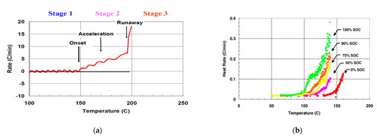
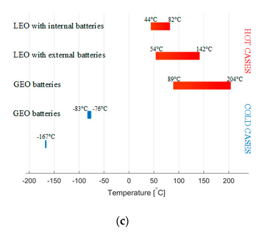
Figure 7.
(a) Cell self-heating rate during forced thermal ramp test (from Ref. [59]).; (b) Accelerating rate calorimetry measurements performed for Sony cells from 0 to 100% SOC [60]. Reprinted from Journal of Power Sources, Vol. 128, E.P. Roth and D.H. Doughty, Thermal abuse performance of high-power 18650 Li-ion cells, pp. 308–318, Copyright (2014), with permission from Elsevier; (c) Temperature range for battery—the worst-case scenarios, adapted from [42].
4. Mission Requirements on Batteries
Mission requirements on batteries are to a large degree determined by the satellite application and its space placement, which are partially mutually coupled. For instance, satellites dedicated to taking detailed and high-resolution pictures of Earth’s surface would be in very close proximity to Earth, typically in the low Earth orbit (LEO). The satellites dedicated to a large surface coverage (e.g., for TV broadcasting and telecommunication) would be placed commonly in geostationary Earth orbit (GEO). The satellite placement can be then divided into LEO, medium Earth orbit (MEO), GEO, and deep space [61]. A large database of CubeSats and nano-satellites can be found in [5]. Orbits of launched nano-satellites are visualized in Figure 8 and it shows that so far nearly all the nano-satellites were dedicated to LEO, except MarCO CubeSats [62], which were deployed in deep space to flyby Mars, and TDO CubeSats intended for geostationary transfer orbit (GTO). The database contains also announced and planned CubeSat missions, besides mainly LEO, missions are targeting MEO, GEO, and various deep-space destinations. The specific placement determines the environmental conditions relevant to batteries, such as periodicity, charging from Sun availability, external temperature factors, and radiation. The requirements in terms of ‘classical’ satellites were summarized by Borthomieu [61] and are shown in Table 6.
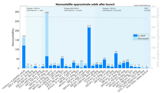
Figure 8.
Launched CubeSats and nano-satellites according to orbits (from Ref. [5]).
Table 6.
The battery requirements for classical satellites according to Borthomieu [61].
Requirements for batteries in CubeSats are similar as for the ‘classical’ satellites, due to the same characteristics of orbits, but they vary in specifics due to the characteristics of CubeSat platform. CubeSats offer a more agile platform with a shorter development cycle. Thus, the speed of development and the cost is prioritized above very high reliability and long lifetime [63]. Consequently, the expected lifetime for batteries in CubeSats is rather less than for larger satellites. According to ESA, the expectations for In-Orbit Demonstration (IOD) missions in LEO are: “low cost and short schedule (typically <1 MEuro and <2 years to flight readiness), short operational lifetime (typically <1 year in low altitude LEO)” [64]. Regular missions in LEO are generally expected to be under five years [10]. The GEO lifetime is expected to be ~5–7 years [63]. Lifetime tests are recommended to determine the technology limitations and required battery sizing. General guidelines for them can be found in the ESA handbook [43]. The tests are divided into calendar and cycling. They can be performed in real-time, or accelerated conditions are used to speed up the process. Specific mission conditions can be incorporated in the tests to get closer to the conditions, which the batteries will experience. However, based on the character of the orbit, generic expectations were formulated for LEO and GEO. A generic real-time LEO orbit lasts 90 min when the battery is charging for 60 min (sunlight) and discharging for 30 min (eclipse). A generic real-time GEO orbit consists of a solstice period and 45 eclipses. The battery is mainly discharged only during the eclipse periods. Thus, cycle-wise, only 45 cycles per season can be considered. The eclipses do not have the same time length, but they vary from the shortest of 21 min to the longest of 72 min. The longest eclipse represent also the deepest discharge that the battery will experience and it is often designed to be 60–80% cycle DOD. The wide study was performed on COTS Li-ion cells lifetime for LEO and GEO missions by ABSL [49,65,66]. It was shown that the battery lifetime depends on many factors and it varies for different cells. Thus, to achieve the target mission life, it is necessary to consider general factors such as cycle DOD, maximum charging voltage, temperature, current rate, and storage SOC. Moreover, an issue with the extrapolation of test results was mentioned, which can lead to predicted values that are wrong. Besides extensive experimental testing, the battery lifetime can also be evaluated through a detailed model, which captures sufficiently their internal mechanisms. Such study, applying a first principles based mathematical model was carried out by Lee et al. [67], where they studied the influence of different cycle DODs in a LEO orbit on battery current, voltage, and lifetime, in a form of end of discharge voltage, as illustrated in Figure 9.
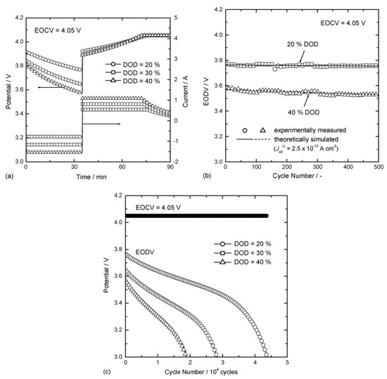
Figure 9.
(a) Potential (voltage) and current profiles simulated for the first LEO cycle; (b) the measured and (c) simulated end-of-discharge voltage (EODV) as a function of cycle number [67]. Reprinted from Journal of Power Sources, Vol. 162, J.-W. Lee et al., Simulation of charge–discharge cycling of lithium-ion batteries under low-earth-orbit conditions, pp. 1395–1400, Copyright (2006), with permission from Elsevier.
For longer missions, the battery lifetime is the most limiting factor. In that case, it bounds the allowable cycle DOD. The cycle DOD per orbit further determines the average charging/discharging current. According to these considerations, the average power, and by that the average current demanded from a single battery cell, is rather low, as shown in Table 6. Typically, the consumption is in a range of Watts for small CubeSats with only body-mounted solar panels. Approximately, it is 2 W power generation per 1 U side covered by solar panels [68]. However, it is necessary to consider that not all solar panels face Sun at the same time. A bus available power can be then roughly linked to CubeSat’s mass (respective size), as shown in Figure 10 [10]. CubeSat power budget can be designed as negative, e.g., 1 U YUsend-1, where average power consumption was 2.2–2.8 W, but the maximum power generation was 2 W. In that case, the satellite had to spend a few orbits in safe mode with average power consumption 1.3 W, in order to recharge the batteries. However, it is more common to design CubeSats with a positive power budget with an average power generation being higher than an average power consumption (e.g., 1.5U DICE with ~1.4 W average power consumption and ~1.7 W average power generation) [69]. CubeSats can be equipped with deployable solar panels and then the expected power consumption can be considerably higher. Larger CubeSats can have power consumption reaching 100 W [12,70]. However, the average power consumption does not determine the required peak power consumption. There can be a payload, or a propulsion system, which needs to draw a large amount of power only for a very limited time (e.g., up to 30 W only for a CubeSat propulsion [71]). In that case, the satellite’s power system still needs to provide a sufficient amount of power, that might require high power from the batteries.
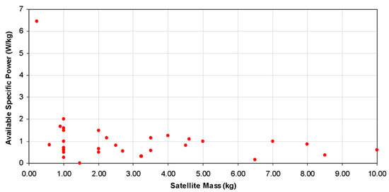
Figure 10.
Available bus power with respect to satellite mass until 2010 according to [10]. Reprinted from Acta Astronautica, Vol. 67, J. Bouwmeester, J. Guo, Survey of worldwide pico- and nanosatellite missions, distributions and subsystem technology, pp. 854–862, Copyright (2010), with permission from Elsevier.
A critical factor for batteries is temperature. The rate of chemical reactions is growing exponentially with temperature, resulting in a fast degradation at high temperatures. Moreover, charging with a too high current at low temperatures also results in rapid degradation due to Lithium plating [72]. The temperature on the spacecraft surface varies significantly and rapidly, and in extreme cases, it can reach over 100 °C or below −100 °C [73]. An example of temperature variations is shown in Figure 11 for the surface and the EPS of GOMX-4 CubeSats at LEO during one day. While the batteries in ‘classical’ satellites experience fairly constant temperature over the year [74], the temperature of batteries in CubeSats is fluctuating noticeably due to the reduced thermal mass of the spacecraft. The battery temperature operating range is determined by its specific composition and the selection of the battery technology then sets the required conditions, which have to be maintained at the spacecraft. The battery temperature is one criterium of spacecraft and mission design. The thermal balance drives the temperature evolution. Externally, the heat is received from external sources (direct sunlight, reflected sunlight, etc) and it is removed by the spacecraft emission. Internally, the payload can be controlled to adjust the generated heat and battery heaters are used when the temperature is too low [20].
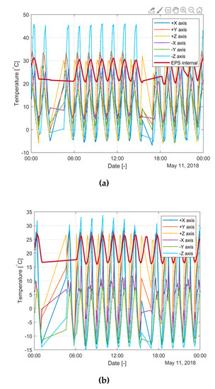
Figure 11.
External temperature distribution from fine sun sensors during no payload operational mode and internal temperature at EPS for (a) GOMX-4A and (b) GOMX-4B [75].
5. Market Status
By screening the market, commercially available battery pack solutions for CubeSats were identified. Prototype solutions developed by universities or (research) institutions, which are not available on the market are not considered. The search for battery manufacturers/suppliers was performed in three web-based databases [5,76,77]. Only publicly available material was considered, which was found often incomplete. However, manufacturers might have additional information available on request about their products. In order to stay neutral and avoid a possible conflict of interest or product advertisement, the specific manufacturer names and the product names were omitted. There were found to be 18 different manufactures and 25 different products (not considering subtypes), as summarized in Table 7.
Table 7.
The battery products available at the market for CubeSats.
By analyzing the market, two types of products containing battery cells were identified. These are the electrical power supply (EPS) and the battery pack (BP). Their market representation is illustrated in Figure 12a. The EPS is a unit that routes and control electrical energy flow in a satellite. It receives the energy from solar panels, it supplies the load, and it exchanges energy with batteries. Thus, the EPS has various converters and it provides electrical buses at various voltage levels (e.g., 3.3 V, 5 V, raw battery voltage, etc.). Some EPSs have integrated battery cells and consequently, they do not necessarily require extra BPs. BPs contain battery cells and some electronic circuitry for proper handling of the cells. From the market survey, it is visible that there are two approaches regarding the battery management system (BMS) (e.g., safety, monitoring and control). In the first approach, a BP is as simple as possible and it dedicates any sophisticated functionality to the EPS, including safety features. In the second approach, a BP is more complex and more self-sufficient unit, integrating most of the BMS functionalities. It is quite common to have protection implemented in the BP, such as over-current (OC), over-voltage (OV), and under-voltage (UV) protection. The OC takes the role of short-circuit (SC) protection as well. Furthermore, some products consider over- or under-temperature protection. It is also not rare that an EPS/BP has heaters, typically to keep the cells above 0 °C, though not all of them. Regarding the cell balancing, it seems that it is not yet so spread among the products. That might be feasible for CubeSats, considering a relative low number of used cells, the possibility of prior matching, and not so long missions.
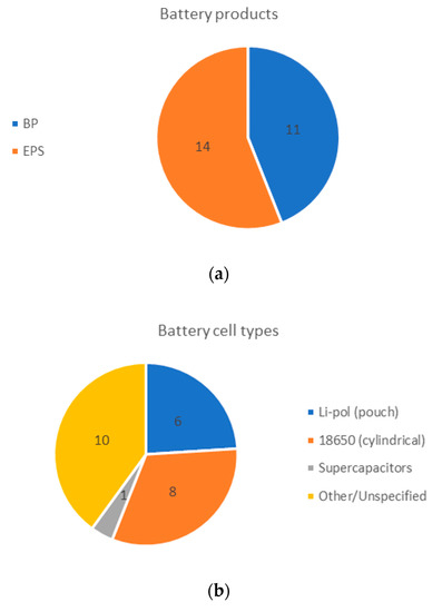
Figure 12.
(a) Distribution of battery products solutions on the market: EPS vs. BP; (b) Types of COTS battery cells (and supercapacitors) available on the market.
A very important parameter is the self-consumption of the system. The critical phase of the CubeSat deployment is detumbling, where extra energy is needed to power up the system and to deploy for example antennas or solar panels and to stabilize the position. At this stage, energy from solar panels might be not available and the batteries have to cover the consumption. If during the transportation, waiting for launch, during launch, waiting for deployment, and deployment, the batteries got too discharged, they might not be able to support the detumbling or they can get also over-discharged and get damaged. Thus, the system is typically equipped with a kill switch, which prevents powering up the extensive circuitry to reduce EPS/BP consumption before the CubeSat deployment. The self-consumption further plays a role during the mission, when it influences a power budget and it has to be accounted for. In Table 7, it is shown that EPS consumption typically ranges between 15 and 160 mW. The self-consumption of only BPs is rather less. It is often divided into two modes: active/operating and non-active/non-operating/quiescent. During the active mode, the self-consumption ranges at 4–20 mA, at a cell voltage of 3.7 V resulting in 14.8–74 mW. During the non-active mode, it is in a range of 3–15 µA, at a cell voltage of 3.7 V resulting in 11.1–55.5 µW.
Both Li-pol pouch cells and 18650 Li-ion cylindrical cells are commonly used, the identified representation is shown in Figure 12b. The Li-pol cells have a capacity of 1.5 Ah. The Li-ion cells are ranging from 2.6 Ah to 3.15 Ah. Based on the EPS/BP size, weight, and energy, the volumetric and gravimetric energy density was computed and it is presented in Table 7 per product. The sorted and visualized independent volumetric/gravimetric energy density is shown in Figure 13a, the coupled volumetric and gravimetric energy density is shown in Figure 13b. The volumetric energy density ranges between 58 and 254 Wh/l for EPSs and 116–343 Wh/l for BPs. The gravimetric energy density is in the range of 41–157 Wh/kg and 94–333 Wh/kg for EPSs and BPs, respectively. Generally, BPs have higher energy density than EPSs; however, there are some EPSs that outperforms other BPs. One type of a BP (2 sub types) has a significantly higher energy density than others, as shown in Figure 13b. It uses an ordinary 1.5 Ah Li-pol cell. The high energy density is reached here by minimalistic mechanical and electronic structure. This BP has only an OC protection and it does not have heaters.
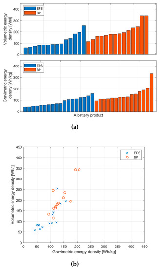
Figure 13.
(a) Distribution of battery products solutions on the market: EPS vs. BP; (b) Types of COTS battery cells (and supercapacitors) available on the market.
The publicly available pricing of the components ranging between 2335 and 7500 Euro for an EPS and 3000–40,000 for a BP, as shown in Table 7. When it is related to an energy unit, it is 58–400 Euro/Wh for an EPS and 65–284 Euro/Wh for a BP. That is approximately by three orders more than a considered automotive price for a pack with 187 Euro/kWh [78]. With further growth of the CubeSat market and increasing production volumes, it can be expected that the price will be decreasing, as it happens in automotive.
6. Conclusions
CubeSats are a growing space industry segment and the batteries are an essential part of every satellite. Unsurprisingly, the Li-ion is the battery chemistry of choice nowadays in the aforementioned applications. In the future, Li-S or solid-state batteries are the prospective technologies. With the consideration of availability and price, COTS battery cells are especially used. However, since they are not dedicated primarily to space applications, their suitability for the space environment has to be assessed. Regarding handling, transportation, and launch, there are many standards posing safety requirements on the batteries. Thus, qualification and flight acceptance tests have to be performed on the batteries for a CubeSat to be allowed to reach the space through the whole logistic chain. Unfortunately, the standards are not unified, which causes a significant test burden on battery manufactures since every launch/deployment provider can have different requirements.
The batteries have to also support the mission throughout their whole life. IOD missions last often less than one year. The regular missions at LEO are expected to take 3–5 years, which can be translated to 16,500–27,500 partial cycles. For batteries to be able to deliver such a high amount of cycles, typically reduced cycle DODs of 10–40% are used. Real-time and accelerated lifetime testing is used to validate an expected battery lifetime.
The market survey of CubeSat battery manufacturers was carried out. Sixteen various manufactures were identified. Battery cells are used in an EPS or in a dedicated battery pack. The most commonly used technologies are Li-pol pouch cells with 1.5 Ah and 18650 cylindrical Li-ion cells, ranging from 2.6–3.15 Ah. There is very high variability in the products regarding their energy density, functionalities, and provided information.
Author Contributions
Conceptualization, V.K. and D.-I.S.; methodology, V.K.; resources, V.K.; data curation, V.K.; writing—original draft preparation, V.K.; writing—review and editing, L.K.V. and D.-I.S.; visualization, V.K.; supervision, D.-I.S.; project administration, V.K, L.K.V. and D.-I.S.; funding acquisition, V.K., L.K.V. and D.-I.S. All authors have read and agreed to the published version of the manuscript.
Funding
This research was funded by Innovation Fund Denmark, grant number 8054-00027B.
Conflicts of Interest
The funders had no role in the design of the study; in the collection, analyses, or interpretation of data; in the writing of the manuscript, or in the decision to publish the results. Some of the authors are employees of GomSpace A/S. The views expressed herein are those of the authors; they do not necessarily reflect the views of GomSpace A/S.
References
- CDS. CubeSat Design Specification. California Polytechnic State University, 2015. Available online: https://www.cubesat.org/s/cds_rev13_final2.pdf (accessed on 29 June 2020).
- GomSpace. Available online: https://gomspace.com/ (accessed on 27 May 2020).
- ISIS. Available online: https://www.isispace.nl/ (accessed on 27 May 2020).
- Woellert, K.; Ehrenfreund, P.; Ricco, A.J.; Hertzfeld, H. Cubesats: Cost-Effective Science and Technology Platforms for Emerging and Developing Nations. Adv. Space Res. 2011, 47, 663–684. [Google Scholar] [CrossRef]
- Kulu, E. Nanosats Database. Available online: https://www.nanosats.eu/ (accessed on 16 June 2020).
- DelPozzo, S.; Williams, C. Nano/Microsatellite Market Forecast, 10th ed.; SpaceWorks Enterprises: Washington, DC, USA, 2020. [Google Scholar]
- Villela, T.; Costa, C.A.; Brandão, A.M.; Bueno, F.T.; Leonardi, R. Towards the Thousandth CubeSat: A Statistical Overview. Int. J. Aerosp. Eng. 2019, 2019, 1–13. [Google Scholar] [CrossRef]
- Camps, A. Nanosatellites and Applications to Commercial and Scientific Missions. In Ionospheric and Atmospheric Threats for GNSS and Satellite Telecommunications; IntechOpen: London, UK, 2019; Volume i, p. 13. [Google Scholar] [CrossRef]
- Saeed, N.; Elzanaty, A.; Almorad, H.; Dahrouj, H.; Al-Naffouri, T.Y.; Alouini, M.-S. CubeSat Communications: Recent Advances and Future Challenges. IEEE Commun. Surv. Tutor. 2020, 1–24. [Google Scholar] [CrossRef]
- Bouwmeester, J.; Guo, J. Survey of Worldwide Pico- and Nanosatellite Missions, Distributions and Subsystem Technology. Acta Astronaut. 2010, 67, 854–862. [Google Scholar] [CrossRef]
- Rao, G.M.; Pandipati, R.C. Satellites: Batteries. In Encyclopedia of Electrochemical Power Sources; Elseiver: Amsterdam, The Netherlands, 2009; pp. 323–337. [Google Scholar]
- Kopacz, J.R.; Herschitz, R.; Roney, J. Small Satellites an Overview and Assessment. Acta Astronaut. 2020, 170, 93–105. [Google Scholar] [CrossRef]
- Pearson, C.; Thwaite, C.; Russel, N. The Use of Small Cell Lithium-Ion Batteries for Small Satellite Applications. In Proceedings of the 18th Annual AIAA/USU Conference on Small Satellites, Logan, UT, USA, 9–12 August 2004; pp. 1–11. [Google Scholar]
- Navarathinam, N.; Lee, R.; Chesser, H. Characterization of Lithium-Polymer Batteries for CubeSat Applications. Acta Astronaut. 2011, 68, 1752–1760. [Google Scholar] [CrossRef]
- Chin, K.B.; Brandon, E.J.; Bugga, R.V.; Smart, M.C.; Jones, S.C.; Krause, F.C.; West, W.C.; Bolotin, G.G. Energy Storage Technologies for Small Satellite Applications. Proc. IEEE 2018, 106, 419–428. [Google Scholar] [CrossRef]
- Uno, M.; Ogawa, K.; Takeda, Y.; Sone, Y.; Tanaka, K.; Mita, M.; Saito, H. Development and On-Orbit Operation of Lithium-Ion Pouch Battery for Small Scientific Satellite “REIMEI”. J. Power Sources 2011, 196, 8755–8763. [Google Scholar] [CrossRef]
- Vanessa, A.; Jacky, C.; Hyvert, J.; Aurelie, G.; Paul, P.J.; Stephane, R.; Yannick, B. MP XLR Battery Range for Constellation. In Proceedings of the 2019 European Space Power Conference (ESPC), Juan-les-Pins, Côte d’Azur, France, 30 September–4 October 2019; pp. 1–8. [Google Scholar] [CrossRef]
- Jacky, C.; Stephane, R.; Yannick, B. VES16 Battery Range: Every Space Application Has a VES16 Solution. In Proceedings of the 2019 European Space Power Conference (ESPC), Juan-les-Pins, Côte d’Azur, France, 30 September–4 October 2019. [Google Scholar]
- 18650batterystore. Available online: https://www.18650batterystore.com/ (accessed on 29 May 2020).
- Poghosyan, A.; Golkar, A. CubeSat Evolution: Analyzing CubeSat Capabilities for Conducting Science Missions. Prog. Aerosp. Sci. 2017, 88, 59–83. [Google Scholar] [CrossRef]
- Gave, G.; Borthomieu, Y.; Lagattu, B.; Planchat, J.-P. Evaluation of a Low Temperature Li-Ion Cell for Space. Acta Astronaut. 2004, 54, 559–563. [Google Scholar] [CrossRef]
- Farmakis, F.; Georgoulas, N.; Karafyllidis, I.; Amoiridis, I.; Elmasides, C.; Balomenou, S.; Tsiplakides, D.; Nestoridi, M. High Specific Energy Lithium Cells for Space Exploration. E3S Web Conf. 2017, 16, 08003. [Google Scholar] [CrossRef]
- Chin, K.B.; Smart, M.C.; Brandon, E.J.; Bolotin, G.S.; Palmer, N.K.; Katz, S.; Flynn, J.A. Li-Ion Battery and Super-Capacitor Hybrid Energy System for Low Temperature SmallSat Applications Conference on Small Satellites. In Proceedings of the Proceedings of the 28th AIAA/USU Conference on Small Satellites, Logan, UT, USA, 4–7 August 2014; pp. 1–7. [Google Scholar]
- Luo, J.; Zhang, W.; Yuan, H.; Jin, C.; Zhang, L.; Huang, H.; Liang, C.; Xia, Y.; Zhang, J.; Gan, Y.; et al. Pillared Structure Design of MXene with Ultralarge Interlayer Spacing for High-Performance Lithium-Ion Capacitors. ACS Nano 2017, 11, 2459–2469. [Google Scholar] [CrossRef] [PubMed]
- Akio, K.; Shuhei, O. In-Orbit Demonstration and Preliminary Study on the Applicability of Lithium-Ion Capacitor to Spacecrafts. In Proceedings of the 2019 European Space Power Conference (ESPC), Juan-les-Pins, Côte d’Azur, France, 30 September–4 October 2019. [Google Scholar]
- Nestoridi, M.; Barde, H. Beyond Lithium-Ion: Lithium-Sulphur Batteries for Space? E3S Web Conf. 2017, 16, 08005. [Google Scholar] [CrossRef]
- Samaniego, B.; Carla, E.; O’Neill, L.; Nestoridi, M. High Specific Energy Lithium Sulfur Cell for Space Application. E3S Web Conf. 2017, 16, 08006. [Google Scholar] [CrossRef]
- Mourembles, D.; Buergler, B.; Gajewski, L.; Cooke, A.; Barchasz, C. Li-S Cells for Space Applications (LISSA). In Proceedings of the 2019 European Space Power Conference (ESPC), Juan-les-Pins, Côte d’Azur, France, 30 September–4 October 2019; pp. 1–5. [Google Scholar] [CrossRef]
- Borthomieu, Y.; Biensan, P.; Nechev, K.; Peres, J.-P. Next Generation of Space Battery Using Solid State Batteries (SSB). In Proceedings of the 2019 European Space Power Conference (ESPC), Juan-les-Pins, Côte d’Azur, France, 30 September–4 October 2019. [Google Scholar]
- Beutl, A.; Zhang, N.; Jahn, M.; Nestoridi, M. All-Solid State Batteries for Space Exploration. In Proceedings of the 2019 European Space Power Conference (ESPC), Juan-les-Pins, Côte d’Azur, France, 30 September–4 October 2019; pp. 1–8. [Google Scholar] [CrossRef]
- Lyman, P.; Olson, J.; Feaver, T. Application of Emerging Structural Energy Storage Technology to Small Satellite Systems. In Proceedings of the Proceedings of the 18th Annual AIAA/USU Conference on Small Satellites, Logan, UT, USA, 9–12 August 2004. [Google Scholar]
- ESA-ESTEC. Space Engineering: Space Environment (ECSS-E-ST-10-04C). ESA Reuqirements and Standards Division, 2008; p. 198. Available online: https://ecss.nl/standard/ecss-e-st-10-04c-space-environment (accessed on 29 June 2020).
- Barth, J.L. Space and Atmospheric Environments: From Low Earth Orbits to Deep Space. In Protection of Materials and Structures from Space Environment; Kluwer Academic Publishers: Dordrecht, The Netherlands, 2003; pp. 7–29. [Google Scholar] [CrossRef]
- Selčan, D.; Kirbiš, G.; Kramberger, I. Nanosatellites in LEO and beyond: Advanced Radiation Protection Techniques for COTS-Based Spacecraft. Acta Astronaut. 2017, 131, 131–144. [Google Scholar] [CrossRef]
- Sinclair, D.; Dyer, J. Radiation Effects and COTS Parts in SmallSats. In Proceedings of the 27th Annual AIAA/USU Conference on Small Satellites, Logan, UT, USA, 12–15 August 2013. [Google Scholar]
- Samwel, S.W.; El-Aziz, E.A.; Garrett, H.B.; Hady, A.A.; Ibrahim, M.; Amin, M.Y. Space Radiation Impact on Smallsats during Maximum and Minimum Solar Activity. Adv. Space Res. 2019, 64, 239–251. [Google Scholar] [CrossRef]
- Qiu, J.; He, D.; Sun, M.; Li, S.; Wen, C.; Hattrick-Simpers, J.; Zheng, Y.F.; Cao, L. Effects of Neutron and Gamma Radiation on Lithium-Ion Batteries. Nucl. Instrum. Methods Phys. Res. Sect. B 2015, 345, 27–32. [Google Scholar] [CrossRef]
- Tan, C.; Leung, K.Y.; Liu, D.X.; Canova, M.; Downing, R.G.; Co, A.C.; Cao, L.R. Gamma Radiation Effects on Li-Ion Battery Electrolyte in Neutron Depth Profiling for Lithium Quantification. J. Radioanal. Nucl. Chem. 2015, 305, 675–680. [Google Scholar] [CrossRef]
- Tan, C.; Lyons, D.J.; Pan, K.; Leung, K.Y.; Chuirazzi, W.C.; Canova, M.; Co, A.C.; Cao, L.R. Radiation Effects on the Electrode and Electrolyte of a Lithium-Ion Battery. J. Power Sources 2016, 318, 242–250. [Google Scholar] [CrossRef]
- Ratnakumar, B.V.; Smart, M.C.; Whitcanack, L.D.; Davies, E.D.; Chin, K.B.; Deligiannis, F.; Surampudi, S. Behavior of Li-Ion Cells in High-Intensity Radiation Environments. J. Electrochem. Soc. 2004, 151, A652. [Google Scholar] [CrossRef]
- Ratnakumar, B.V.; Smart, M.C.; Whitcanack, L.D.; Davies, E.D.; Chin, K.B.; Deligiannis, F.; Surampudi, S. Behavior of Li-Ion Cells in High-Intensity Radiation Environments: II. Sony/AEA/ComDEV Cells. J. Electrochem. Soc. 2005, 152, A357. [Google Scholar] [CrossRef]
- Bausier, F.; Nestoridi, M.; Samaniego, B.; Simola, J.; Wolahan, A.; Austin, J.; Soares, T. Spacecraft Electrical Passivation: From Study to Reality. E3S Web Conf. 2017, 16, 13002. [Google Scholar] [CrossRef]
- ESA-ESTEC. Space Engineering Li-Ion Battery Testing Handbook (ECSS-E-HB-20-02A); ESA Reuqirements and Standards Division: Noordwijk, The Netherlands, 2015; pp. 1–31. [Google Scholar]
- European Space Components Coordination. Total Dose Steady-State Irradiation Test Method Escc Basic Specification No. 22900. Available online: http://escies.org/escc-specs/published/22900.pdf (accessed on 27 May 2020).
- ESA-ESTEC. Space Product Assurance Radiation Hardness Assurance–EEE Components (ECSS-Q-ST-60-15C). 2012. Available online: https://ecss.nl/standard/ecss-q-st-60-15c-radiation-hardness-assurance-eee-components-1-october-2012/ (accessed on 27 May 2020).
- Initiative, N.C.L. CubeSat 101: Basic Concepts and Processes for First-Time CubeSat Developers. NASA 2017, 2017, 96. [Google Scholar]
- ESA-ESTEC. Space Product Assurance Thermal Vacuum Outgassing Test for the Screening of Space Materials (ECSS-Q-ST-70-02C). 2008. Available online: https://ecss.nl/standard/ecss-q-st-70-02c-thermal-vacuum-outgassing-test-for-the-screening-of-space-materials/ (accessed on 27 May 2020).
- Jeevarajan, J. Requirements for Flight Certification and Acceptance of Commercial off the Shelf (Cots) Lithium-Ion (Li-Ion) Batteries (JSC 66548); Engineering Directorate Energy, Systems Division, NASA: Washington, DC, USA, 2013; pp. 1–24.
- Clarke, A.; Buckle, R. Identification of COTS Cells to Meet Space Market Segment Requirements. In Proceedings of the 2019 European Space Power Conference (ESPC), Juan-les-Pins, Côte d’Azur, France, 30 September–4 October 2019; pp. 1–4. [Google Scholar] [CrossRef]
- Motohata, T.; Shimizu, T.; Masui, H.; Cho, M. Development of a Testing Standard of COTS Lithium-Ion Batteries for Nano-Satellite. In Proceedings of the 65th International Astronautical Congress (IAC), Toronto, Canada, 29 September–3 October 2014. [Google Scholar]
- ESA Reuqirements and Standards Division. Space Engineering: Testing (ECSS-E-ST-10-03C). Available online: https://ecss.nl/standard/ecss-e-st-10-03c-testing/ (accessed on 27 May 2020).
- ESA/ESTEC. Tailoring of ECSS Engineering Standards for In-Orbit Demonstration CubeSat Projects. 2013. Available online: https://copernicus-masters.com/wp-content/uploads/2017/03/IOD_CubeSat_ECSS_Eng_Tailoring_Iss1_Rev3.pdf (accessed on 27 May 2020).
- United Nations. Recommendations on the Transport of Dangerous Goods, Manual of Tests and Criteria ST/SG/AC.10/11/Rev.5. Available online: http://www.unece.org/index.php?id=41869 (accessed on 27 May 2020).
- Bandhauer, T.M.; Garimella, S.; Fuller, T.F. A Critical Review of Thermal Issues in Lithium-Ion Batteries. J. Electrochem. Soc. 2011, 158, R1. [Google Scholar] [CrossRef]
- Carré, A.; Ruiz, R.A. Overview of Current Safety Requirements for the On-Ground Handling and Transportation of Li-Ion Cells and Batteries for Space Applications. In Proceedings of the 2019 European Space Power Conference (ESPC), Juan-les-Pins, Côte d’Azur, France, 30 September–4 October 2019. [Google Scholar]
- Engineering Directorate Energy Systems Division, NASA. Crewed Space Vehicle Battery Safety Requirements (JSC 20793 Rev D). Available online: https://standards.nasa.gov/standard/jsc/jsc-20793 (accessed on 27 May 2020).
- Space Systems—Space Debris Mitigation Requirements, ISO 24113. Available online: https://www.iso.org/standard/72383.html (accessed on 27 May 2020).
- Aouizerate, M.; Samaniego, B.; Bausier, F.; Nestoridi, M. Spacecraft Battery Passivation. In Proceedings of the 2019 European Space Power Conference (ESPC), Juan-les-Pins, Côte d’Azur, France, 30 September–4 October 2019. [Google Scholar]
- Doughty, D.H. Li-Ion Battery Abuse Tolerance Testing—An Overview. Available online: https://www.yumpu.com/en/document/view/3098930/li-ion-battery-abuse-tolerance-testing-an-overview (accessed on 27 May 2020).
- Roth, E.; Doughty, D. Thermal Abuse Performance of High-Power 18650 Li-Ion Cells. J. Power Sources 2004, 128, 308–318. [Google Scholar] [CrossRef]
- Borthomieu, Y. Satellite Lithium-Ion Batteries. In Lithium-Ion Batteries; Elsevier: Amsterdam, The Netherlands, 2014; pp. 311–344. [Google Scholar] [CrossRef]
- Krause, F.C.; Loveland, J.A.; Smart, M.C.; Brandon, E.J.; Bugga, R.V. Implementation of Commercial Li-Ion Cells on the MarCO Deep Space CubeSats. J. Power Sources 2020, 449, 227544. [Google Scholar] [CrossRef]
- Sweeting, M.N. Modern Small Satellites-Changing the Economics of Space. Proc. IEEE 2018, 106, 343–361. [Google Scholar] [CrossRef]
- ESA/ESTEC. Product and Quality Assurance Requirements for In-Orbit Demonstration CubeSat Projects. 2013. Available online: http://emits.sso.esa.int/emits-doc/ESTEC/AO8352_AD2_IOD_CubeSat_PQA_Reqts_Iss1_Rev1.pdf (accessed on 27 May 2020).
- Buckle, R.; Roberts, S. Review of Commercial Cells For Space Applications. E3S Web Conf. 2017, 16, 17006. [Google Scholar] [CrossRef]
- Buckle, R. Life Testing of COTS Cells for Optimum Battery Sizing. In Proceedings of the 2019 European Space Power Conference (ESPC), Juan-les-Pins, Côte d’Azur, France, 30 September–4 October 2019; pp. 1–7. [Google Scholar] [CrossRef]
- Lee, J.-W.; Anguchamy, Y.K.; Popov, B.N. Simulation of Charge-Discharge Cycling of Lithium-Ion Batteries under Low-Earth-Orbit Conditions. J. Power Sources 2006, 162, 1395–1400. [Google Scholar] [CrossRef]
- Notani, S.; Bhattacharya, S. Flexible Electrical Power System Controller Design and Battery Integration for 1U to 12U CubeSats. In Proceedings of the 2011 IEEE Energy Conversion Congress and Exposition, Phoenix, AZ, USA, 17–22 September 2011; pp. 3633–3640. [Google Scholar] [CrossRef]
- Bugryniec, P. CubeSat: The Need for More Power to Realise Telecommunications Overview of CubeSats Aims & Objectives. 2016. Available online: http://www.energystorage-cdt.ac.uk/outputs/cohort-2/Bugryniec+mini+project+report.pdf (accessed on 27 May 2020).
- Small Spacecraft Technology State of the Art. Available online: https://www.nasa.gov/sites/default/files/atoms/files/small_spacecraft_technology_state_of_the_art_2015_tagged.pdf (accessed on 27 May 2020).
- Gary, Q.; Boris, S.; Christophe, K.; Benoît, M. Attitude Control: A Key Factor during the Design of Low-Thrust Propulsion for CubeSats. Acta Astronaut. 2020, 176, 40–51. [Google Scholar] [CrossRef]
- Barré, A.; Deguilhem, B.; Grolleau, S.; Gérard, M.; Suard, F.; Riu, D. A Review on Lithium-Ion Battery Ageing Mechanisms and Estimations for Automotive Applications. J. Power Sources 2013, 241, 680–689. [Google Scholar] [CrossRef]
- Fortescue, P.; Swinerd, G.; Stark, J. Spacecraft Systems Engineering; Fortescue, P., Swinerd, G., Stark, J., Eds.; John Wiley & Sons, Ltd.: Chichester, UK, 2011. [Google Scholar] [CrossRef]
- Bard, F.; Carré, A.; Fernandez, P.; Nestoridi, M.; Alia, S.; Datta, A.; Durodola, O. In-Orbit Trend Analysis of Galileo Satellites for Power Sources Degradation Estimation. E3S Web Conf. 2017, 16, 13005. [Google Scholar] [CrossRef]
- Pérez, L.L.; Koch, P.; Walker, R. GOMX-4—The Twin European Mission for IOD Purposes. In Proceedings of the 32nd Annual AIAA/USU Conference on Small Satellites, Logan, UT, USA, 6–9 August 2018. [Google Scholar]
- Cubesat - Suppliers. Available online: https://www.cubesat.org/suppliers (accessed on 16 June 2020).
- Satsearch. The Global Marketplace for the Space. Available online: https://satsearch.co/products/categories/satellite/power/battery/products?page=1 (accessed on 16 June 2020).
- Nykvist, B.; Sprei, F.; Nilsson, M. Assessing the Progress toward Lower Priced Long Range Battery Electric Vehicles. Energy Policy 2019, 124, 144–155. [Google Scholar] [CrossRef]


© 2020 by the authors. Licensee MDPI, Basel, Switzerland. This article is an open access article distributed under the terms and conditions of the Creative Commons Attribution (CC BY) license (http://creativecommons.org/licenses/by/4.0/).