Abstract
This paper proposes a permanent magnet synchronous machine (PMSM) table-based torque control method considering a variable DC-link voltage that can be used in a low cost DSP. The current reference generation based on two-dimensional look-up table (2D-LUT) is widely used for PMSM drives used in industrial applications because of its torque control performance and operation stability. In general, a 2D-LUT is established based on the flux and torque to overcome the variation in DC-link voltage. However, this method requires a flux estimator for estimating the instantaneous flux, which is defined as a division of the operating speed used to obtain the flux data. Therefore, to obtain the operating flux, a variable division calculation or complex controller is used, which can be difficult to process through a low cost digital signal processor. In this paper, a novel look-up table-based control method that uses the newly established speed-torque 2D-LUT is proposed. This 2D-LUT inherently implements data on the d-/q-axis currents throughout the operating regions, not only the speed and torque, but also the DC-link voltage variation. The proposed method was verified through an experiment on the torque control a variation in the DC-link voltage.
1. Introduction
Permanent magnet synchronous machines (PMSM) have been adopted for improving efficiency of the mechanical drive in various industrial applications. In this area of applications, the PMSM drive was developed for low cost but robust control performance which is always the task to motor drive engineers. Presently, the cost of digital signal processor (DSP) is reducing due to technology improvements; however, the price of DSP is still one of the most expensive component in PMSM drive. Although the cost of fixed point DSP is much smaller than the cost of floating point DSP, complex and robust control algorithm cannot be easily adapted with fixed point DSP because it can only handle integer variable.
On the other hand, to achieve the robust torque control for PMSM drive, look-up table (LUT) based current control has been widely adopted to generate a current reference for precise torque generation corresponding to the torque reference. This LUT is established experimentally under extreme conditions in order to consider the inductance saturation or resistance variation, and thus the target drive has a steady torque generation against variations in the guaranteed operation range []. A general LUT-based PMSM drive uses a two-dimensional look-up Table (2D-LUT), speed-torque [,,], or flux-torque [,,,,] for reference. Figure 1 shows these control methods. A speed-torque 2D-LUT-based control method has a simple control algorithm. As shown in Figure 1a, it does not require any specific processes for 2D-LUT usage, and it is, therefore, comparatively convenient to adapt in a low cost PMSM drive. However, there is no way to reflect the DC-link voltage variation, and the 2D-LUT has to be made under the minimum voltage of DC-link for a stable operation against the variation in DC-link voltage. Due to this reason, the controllable power is reduced to a level that can occur at the minimum DC link voltage. To reflect this variation in the DC-link voltage, a torque control method using flux-torque table is generally applied on the PMSM drive as shown in Figure 1b. Although a flux estimator and a torque limiter are required, controllable power is enlarged due to the estimated flux automatically reflects the DC-link voltage variation. However, to implement this method in a low cost DSP, the flux estimator has a considerable processing burden because it requires a variable division calculation [,] or a controller with variable gain, which has been obtained from experiments conducted under various DC-link voltage conditions [,]. Other studies have reflected the variation in DC-link voltage, and the method in [,] uses a three-dimensional LUT (3D-LUT), which increases the number of LUT inputs for reflecting the DC-link voltage. However, these methods require excessive amounts of experimental data and allowable memory, as well as a complex interpolation method. To exclude methods using a flux estimator and 3D-LUT, a speed-torque 2D-LUT-based control method considering the variation in DC-link voltage is proposed in [,,,]. These studies indicate that if the ratio of the current to nominal value of the DC-link voltage is applied to the speed information, it can control the motor reflecting the variation in DC-link voltage despite the use of speed-torque 2D-LUT. However, these methods also require a variable division calculation to obtain the voltage ratio, and as a result, they cannot be easily implemented in a low cost DSP.
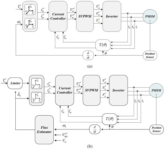
Figure 1.
Conventional torque control methods based on 2D-LUT: (a) speed-torque table-based control and (b) flux-torque table-based control.
In this paper, a simple torque control method for PMSM is proposed considering the variation in DC-link voltage, which can be easily adopted in a low cost DSP. The proposed method uses a speed-torque 2D-LUT for the generation of the d-/q-axis currents reference. However, a calculation process to obtain the DC-link voltage ratio is not needed, which is essential for reflecting the current DC-link voltage in [,,,]. The proposed control method was verified through an experiment under various DC-link voltage conditions.
This paper is organized as follows. In Section 2, the concept of the proposed method is given and how to establish the speed-torque table considering DC-link voltage variation are presented with the experimental set-up for verification. In Section 3, experiments are conducted to prove the proposed method. The conclusion of this paper is given in Section 4.
2. Proposed PMSM Torque Control Method Based on 2D-LUT
2.1. Composition of Proposed Control Method
First, a general model equation of the PMSM can be expressed as follows.
where are synchronous d-/q-axis voltages, respectively. are synchronous d-/q-axis currents, respectively. is phase resistance. are d-/q-axis inductances respectively. is angular speed. is permanent magnet flux. is motor torque. P is motor poles.
Under the steady-state operation, the back-EMF of the PMSM is described through (3) ignoring the relatively small stator resistance. If the flux weakening operation region is restricted under the linear modulation region, the maximum allowable back-EMF voltage can be described through (4).
where is the back-EMF magnitude of the PMSM. is the maximum allowable back-EMF voltage. is DC-link voltage. In general, the difference between (3) and (4) is inserted into the PI controller to calculate a suitable LUT input for a flux weakening operation. In the speed-torque 2D-LUT-based control method, the modified speed that reflects the current DC-link voltage is inserted into the LUT [,,,]. Figure 2 shows the proposed and conventional control block diagrams.
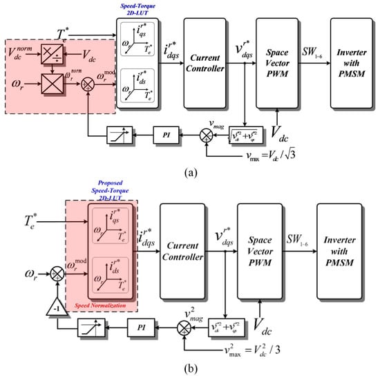
Figure 2.
Overall speed-torque 2D-LUT-based PMSM control block diagram: (a) conventional [,,,] and (b) proposed methods.
The proposed control method does not require a calculation block to apply the current DC-link voltage information to the speed, which differs from a conventional control method. Instead of this calculation block, the proposed method increases/decreases the speed information through the PI controller output from the difference between (3) and (4), and then modifies the LUT data composition to reflect the variation in the DC-link voltage.
Please note that the PI controller provides robustness to the uncertainty and variation in machine parameters such as the stator resistance and inductance; although the back-EMF voltage is affected by such variation in the parameters, the output of the PI controller mitigates the effect [,,]. To reduce the computational complexity, the squared values of (3) and (4) are inserted into the PI controller to remove the sqrt function. This reduces the processing burden for the DSP.
2.2. Establishment of Speed-Torque Look-Up Table for Reflection of DC-Link Voltage
As previously mentioned, since the torque control method based on the speed-torque table cannot reflect the variation in the DC-link voltage, the d-/q-axis currents data are obtained at the minimum DC-link voltage to prevent a voltage saturation. In this study, the nominal DC-link voltage of the proposed control method is the maximum allowable DC-link voltage. As explained in [], the d-/q-axis currents curves for the maximum torque per ampere (MTPA) and the maximum torque per voltage (MTPV) are the operation boundaries, which means the variation in DC-link voltage has no effect. Therefore, the proposed methods used to obtain the d-/q-axis currents data for the MTPA and MTPV are the same as in the conventional LUT method [,]. However, the d-/q-axis currents data for the flux weakening region must be modified because such data are affected by the variation in the DC-link voltage.
If the speed-torque 2D-LUT is established for the nominal DC-link voltage , the voltage restriction of proposed 2D-LUT can be described as follows:
To change d-/q- currents in DC-link voltage variation, the currents data for a certain speed should be defined as . If certain DC-link voltage is , is described as (6).
If the DC-link voltage is changed from to (, d-/q- axis currents should be changed for the fixed torque generation. In Figure 3, the changed d-/q- axis currents for the DC-link voltage variation is shown. When the restricted back-EMF voltage ellipse is changed with DC-link voltage as (4), changed d-/q-currents which expressed as the green line of Figure 3 can be obtained from a complicated calculation, which is the root of the fourth-order equation from (2) and (5) []. However, these d-/q-axis currents data for a varied DC-link voltage are stored in the LUT by the d-/q-axis currents of . In this case, modified speed according to changed is only required for reflection of current DC-link voltage. First, the ratio of the current DC-link voltage to the nominal DC-link voltage is herein. With this coefficient, the variation in is calculated using (7).
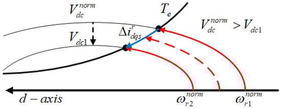
Figure 3.
d-/q-axis currents trajectory on DC-link voltage variation.
As described in (7), is simply proportional to the varied DC-link voltage. If is substituted into (5), the speed normalized by the DC-link voltage is easily obtained through (8).
As shown in Figure 3, the d-/q-axis currents set of must be moved to the current set of for a diminished DC-link voltage from to . To adapt this concept, the proposed controller described in Figure 2b regulates the speed input of 2D-LUT using a feedback controller, which reflects the current DC-link voltage. decreases more than the actual speed as the voltage increases. This is because the restricted voltage ellipse is expanded. On the other hand, increases more than the actual motor speed as the DC-link voltage decreases because the restricted voltage ellipse is diminished. To determine a proper , which is defined as a multiplication of and DC-link voltage ratio obtained from the feedback controller, which regulates the estimated back-EMF to the restricted voltage. Please note that this feedback controller reflects not only the current DC-link voltage but also the variation in motor parameters, as revealed from the estimated back-EMF. Therefore, this controller facilitates a stable control of the target PMSM.
To reflect the DC-link voltage variation by speed input, the speed-torque table using in the controller can reflect all possible DC-link voltage conditions. Unfortunately, the 2D-LUT made by conventional establishment method can not reflect this voltage variation. Figure 4 shows the difference between conventional and proposed speed-torque table. In conventional speed-torque 2D-LUT as shown in Figure 4a, each speed in 2D-LUT reflects only one point of DC-link voltage. Therefore, if we set the DC-link voltage as , the voltage limit ellipse of the maximum speed is defined under the condition that the DC-link voltage is . However, proposed 2D-LUT can reflect more shrunken voltage limit ellipse as shown in Figure 4b. In the first procedure to establish the proposed speed-torque table, the proposed method requires the d-/q-axis currents data obtained experimentally under the condition of the minimum DC-link voltage. Using this procedure, the d-/q-axis currents data located at the most shrunken voltage-limit ellipse can be obtained, as shown in the grey line of Figure 4. In the second procedure, to transform the d-/q-axis currents data for each speed at the minimum DC-link voltage into the current data for each speed at the nominal DC-link voltage, the assigned speed information has to be modified using this equation.
where is the speed of the minimum DC-link voltage.
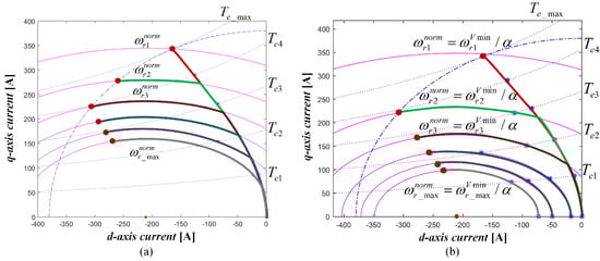
Figure 4.
Speed-torque 2D-LUT established using 6X6 memory map (a) Speed-torque 2D-LUT established under (b) Proposed speed-torque 2D-LUT configuration.
In this case, is the ratio of the minimum DC-link voltage to the nominal DC-link voltage. As the final procedure, the speed-torque 2D-LUT is constructed using the d-/q-axis currents sets of each modified speed. Please note that the maximum modified speed is consistently over the practical maximum speed because in (9) is consistently below 1. For instance, when the DC-link voltage is decreased from the nominal value, is increased, as shown in Figure 2b, owing to the voltage feedback controller, which reflects the decreased DC-link voltage. Because the d-/q-axis currents set for a higher speed is the d-/q-axis currents set for the decreased DC-link voltage, it can generate suitable d-/q-axis currents for variation in the DC-link voltage with the voltage feedback controller. Moreover, the d-/q-axis currents data implemented in the proposed speed-torque 2D-LUT are established experimentally under the condition of extreme temperature and the smallest allowable DC-link voltage, and the d-/q-axis currents data consider not only the DC-link voltage variation but also variations in the motor parameters such as the inductance or resistance. Therefore, the proposed 2D-LUT generates suitable d-/q-axis currents in accordance with the torque reference under all conditions within the allowable range of the DC-link voltage.
2.3. Experimental Setup
The parameters of the target motor used in this study are shown in Table 1. The rated power of the target motor is 80 kw. Because the center of the voltage limit ellipse is inside the current limit circle, the motor in theory can be controlled at an infinite speed. However, because of the durability and mechanical constraint of the system, the maximum speed of the target motor is 8000 rpm.

Table 1.
MOTOR PARAMETERS.
Figure 5 shows a picture and a diagram of the experimental setup. As shown in Figure 5a, target PMSM is controlled by the target inverter, and it is connected with IM load controlled by commercial load inverter. Load inverter controls load motor according to the speed command.
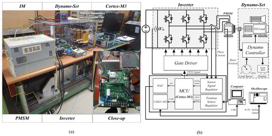
Figure 5.
Experimental setup (a) Picture of experimental setup (b) Composition of the experimental setup.
Target inverter is composed of 6-switch inverter and the controller as shown in Figure 5b. The micro control unit (MCU) of this controller is Cortex M3 from ARM corporation to verify the proposed control algorithm is effective in low cost motor drive system. The DC-link voltage is directly affected by the DC power supply output for testing under variable DC-link voltage condition.
3. Results and Discussion
The speed-torque 2D-LUT is created based on a DC-link voltage of 260 V, and the speed data should be modified into the speed data based on a DC-link voltage of 380 V using the method presented in Section 3, and stored into memory. Figure 6 shows the current map stored into memory.
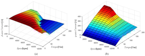
Figure 6.
Proposed d-/q-axis currents map: (a) d-axis and (b) q-axis.
Because the value of calculated by (7) is 0.6842, the current map data should be generated for a maximum motor speed of at least 11,693 rpm. In conclusion, the maximum motor speed for the stored current data should be higher than the actual maximum motor speed to compensate the current reference in case of a variation in the DC-link voltage by adjusting .
The proposed 2D-LUT, however, can perform the maximum power control with different DC-link voltages. Figure 7 shows the experimental result of maximum power control under minimum and maximum DC-link voltage and this experiment was conducted in room temperature. Figure 7a,b are waveforms under maximum (380 V) and minimum (260 V) DC-link voltage respectively, and it is shown that the output is varied according to the input voltage. Also, the motor speed is varied from rated speed to 8000 rpm by the load motor during the experiment.
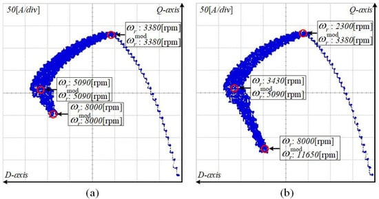
Figure 7.
d-/q-axis currents trajectory for maximum torque driving with different DC-link voltages: (a) DC-link voltage of 380 V and (b) DC-link voltage of 260 V.
As mentioned earlier, the proposed d-/q-axis currents map is obtained under the allowable maximum temperature for the stable performance in the circumstance variation. Since the resistance value increases/decreases as the temperature increases/decreases, the voltage limit ellipse is shrunk/extended according to the operating temperatures. Therefore, the proposed method automatically generates proper current map corresponding to 8000 rpm which is the maximum speed for varied voltage limit ellipse in any operating conditions.
As shown in Figure 7b, the value of is 11,650 rpm during the motor is rotating at 8000 rpm, which current map data are for the more extended voltage limit ellipse, while the value from the calculation is 11,693 rpm. This is because the voltage drop from the resistance is reduced resulting in voltage limit ellipse extension.
Meanwhile, Figure 7a shows that has the same value as the actual speed of the motor. The reason is as follows. Even if the converted gain value is applied to the map, the converted speed, should be smaller value than the speed of the map. Because, stored d-/q-axis currents data is under high temperature experiment for reflecting the largest ohmic voltage drop.
However, the proposed voltage controller controls less then the practical speed, increasing maximum power in flux-weakening region due to increasing DC-link voltage is restricted, even though practical controllable power is extended due to diminished ohmic voltage drop from room temperature. Although the limit is existed in the proposed control method, the difference is not significant because it is as much an error as an ohmic voltage drop caused from the temperature variation.
Figure 8 shows the d-/q-axis currents trajectories when the DC-link voltage is varied by 20 V from 380 V to 260 V, and 130 Nm of the torque reference is input at a constant motor speed of 3000 rpm.
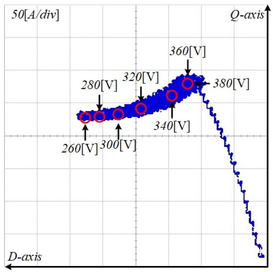
Figure 8.
d-/q-axis currents trajectory for constant torque control with variable DC-link voltage (DC-link voltage of 380 V to 260 V, constant motor speed of 3000 rpm, and torque reference of 130 [Nm]).
From 380 V to 340 V of the DC-link voltage, the current references are the same because the DC-link voltage is capable of achieving the maximum torque control from the MTPA curve. When the DC-link voltage is changed from 340 V to 260 V, the current references are changed into the references for a flux-weakening operation because the torque controller can no longer track the MTPA curve with a decreased DC-link voltage.
It has been shown that even if the DC-link voltage is changed during the operation, the proposed method achieves the maximum torque control according to the DC-link voltage variation when adjusting the current references along with the DC-link voltage.
Figure 9 shows the experimental results for constant torque control with a variable DC-link voltage.
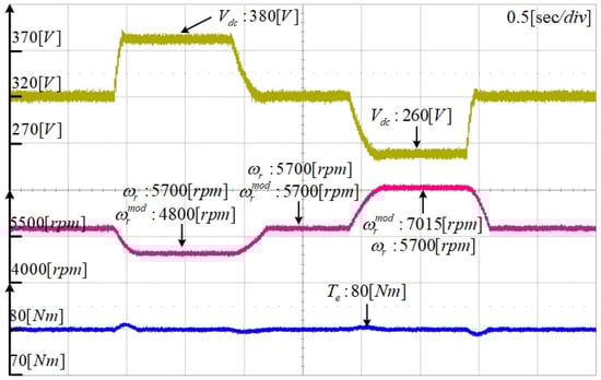
Figure 9.
Constant torque control using proposed method during DC-link voltage variation.
Using the proposed method, the speed of the motor is controlled at 4800 rpm, the torque is 80 [Nm], the DC-link voltage is 320 V, and is calculated as 5700 rpm.
When the DC-link voltage is changed to 380 V, the calculated speed is decreased to 4800 rpm to maintain the output torque. As a result, the output torque incurs a small fluctuation but remains almost unchanged.
When the DC-link voltage is returned to 320 V and then changed to 260 V, the calculated speed is increased to 7015 rpm to maintain the torque, which as before is also not severely changed.
In conclusion, if the DC-link voltage increases, gradually decreases and increases if the DC-link voltage decreases, resulting in almost the same output torque without an additional device or excessive memory capacity.
Figure 10 shows the experiment results of the maximum torque and power under various conditions of the DC-link voltage. An increase or decrease in the DC-link voltage is reflected by the feedback controller, which tunes the speed input of the 2D-LUT. As shown in the figure, the rated speed is increased in accordance with the increased DC-link voltage. For this reason, the maximum torque at the specific speed in the flux weakening region is increased even it does not use the flux-torque 2D-LUT to reflect the DC-link voltage. Therefore, the maximum power is also extended in accordance with increasing DC-link voltage.
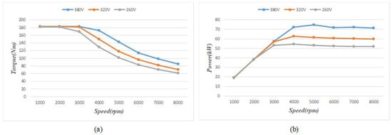
Figure 10.
Experiment results of (a) maximum torque and (b) power using the proposed method (380, 320, and 260 V).
These results prove that an appropriate torque control is achieved, not only at a DC-link voltage of 260 V but also at 320 V and 380 V by means of a general feedback control using a novel speed-torque 2D-LUT.
4. Conclusions
In this paper, a PMSM torque control method considering the DC-link voltage variation with a speed-torque 2D-LUT was proposed. Conventionally, d-/q-axis currents references from the flux-torque 2D-LUT have been used for reflecting the variation in DC-link voltage. However, this method requires a comparatively complex composition, such as a variable division, the establishment of an LUT, and verification of the current maps. In contrast, the proposed torque control method can be implemented in a low-cost microprocessor with only fixed-point arithmetic owing to its simple structure and easy calculation process. The proposed control method was verified experimentally that the controlled torque is sustained although the DC-link voltage varied, moreover, controllable power is expanded according to the increased DC-link voltage as same as the conventional complex algorithm for DC-link voltage variation.
Author Contributions
Conceptualization, J.-H.L.; formal analysis, visualization and writing—original draft preparation, J.-H.L.; experiment, D.-Y.K.; validation, D.-Y.K.; writing—review and editing, D.-Y.K. and J.-H.L. All authors have contributed to the manuscript. All authors have read and agreed to the published version of the manuscript.
Funding
This research received no external funding.
Acknowledgments
This research was supported by the National Research Foundation of Korea (Grant number: NRF-2018R1C1B6008895); and the Basic Science Research Program through the National Research Foundation of Korea (NRF), funded by the Ministry of Education (NRF-2016R1A6A1A03013567).
Conflicts of Interest
The authors declare no conflict of interest.
References
- Kim, S.; Seok, J.K. Maximum Voltage Utilization of IPMSMs Using Modulating Voltage Scalability for Automotive Applications. IEEE Trans. Power Electron. 2013, 28, 5639–5646. [Google Scholar] [CrossRef]
- Park, J.H.; Lee, J.H.; Lee, J.H.; Won, C.Y. Current control method of IPMSM in constant power region for HEV. In Proceedings of the 2011 International Conference on Electrical Machines and Systems, Beijing, China, 20–23 August 2011. [Google Scholar] [CrossRef]
- Lee, J.H.; Lee, J.H.; Park, J.H.; Won, C.Y. Field-weakening strategy in condition of DC-link voltage variation using on electric vehicle of IPMSM. In Proceedings of the 2011 International Conference on Electrical Machines and Systems, Beijing, China, 20–23 August 2011. [Google Scholar] [CrossRef]
- Yang, N.; Luo, G.; Liu, W.; Wang, K. Interior permanent magnet synchronous motor control for electric vehicle using look-up table. In Proceedings of the 7th International Power Electronics and Motion Control Conference, Harbin, China, 2–5 June 2012; pp. 1015–1019. [Google Scholar] [CrossRef]
- Cheng, B.; Tesch, T.R. Tesch, Torque feedforward control technique for permanent-magnet synchronous motors. IEEE Trans. Ind. Electron. 2010, 57, 969–974. [Google Scholar] [CrossRef]
- Kwon, T.S.; Choi, G.Y.; Kwak, M.S.; Sul, S.K. Novel flux-weakening control of an IPMSM for quasi-six-step operation. IEEE Trans. Ind. Appl. 2008, 44, 1722–1731. [Google Scholar] [CrossRef]
- Bae, B.H.; Patel, N.; Schulz, S.; Sul, S.K. New field weakening technique for high saliency interior permanent magnet motor. In Proceedings of the 38th IAS Annual Meeting on Conference Record of the Industry Applications Conference, Salt Lake City, UT, USA, 12–16 October 2003; pp. 898–905. [Google Scholar] [CrossRef]
- Armando, E.; Bojoi, R.I.; Guglielmi, P.; Pellegrino, G.; Pastorelli, M. Experimental Identification of the Magnetic Model of Synchronous Machines. IEEE Trans. Ind. Appl. 2013, 49, 2116–2125. [Google Scholar] [CrossRef]
- Nalepa, R.; Orlowska-Kowalska, T. Optimum Trajectory Control of the Current Vector of a Nonsalient-Pole PMSM in the Field-Weakening Region. IEEE Trans. Ind. Electron. 2011, 59, 2867–2876. [Google Scholar] [CrossRef]
- Feynman, R.P.; Vernon, F.L., Jr. The Theory of a General Quantum System Interacting with a Linear Dissipative System. U.S. Patent US5569995A, 1996. [Google Scholar] [CrossRef]
- Lee, J.H.; Won, C.Y.; Lee, B.K.; Kim, H.B.; Baek, J.H.; Han, K.B.; Chung, U.I. IPMSM torque control method considering DC-link voltage variation and friction torque for EV/HEV applications. In Proceedings of the 2012 IEEE Vehicle Power and Propulsion Conference, Seoul, Korea, 9–12 October 2012; pp. 1063–1069. [Google Scholar] [CrossRef]
- Lee, J.H.; Won, C.Y. A Performance Improvement Method of PMSM Torque Control Considering DC-link Voltage Variation. J. Korean Inst. Illum. Electr. Install. Eng. 2014, 28, 112–122. [Google Scholar] [CrossRef]
- Trancho, E.; Ibarra, E.; Arias, A.; Kortabarria, I.; Jurgens, J.; Marengo, L.; Fricasse, A.; Gragger, J.V. PM-Assisted Synchronous Reluctance Machine Flux Weakening Control for EV and HEV Applications. IEEE Trans. Ind. Electron. 2018, 65, 2986–2995. [Google Scholar] [CrossRef]
© 2020 by the authors. Licensee MDPI, Basel, Switzerland. This article is an open access article distributed under the terms and conditions of the Creative Commons Attribution (CC BY) license (http://creativecommons.org/licenses/by/4.0/).