Abstract
A supercapacitor is a potential energy system that will be a part of an efficient storage device of renewable energy, such as a small battery and a large energy storage system (ESS), etc. However, a lot of efforts have been devoted to improving stability. Generally, ABO3-type perovskite structure has been studied as an electrode and/or an oxide ion-conducting electrolyte for solid oxide fuel cells with stable structural stability at high temperatures. In this study, perovskite material (La0.8Sr0.2Mn0.5Co0.5O3-δ. LSMCO) was added as a component of the supercapacitor electrode for enhanced stability. According to electrochemical measurements, at 5 mV/s, the specific capacitance of the graphene-based electrode (G95) is 68 F/g, and the electrode mixed with perovskite (G70L25) is 55 F/g. Nonetheless, the standard deviation of the capacitance value of G70L25 is smaller than that of G95. Alongside this, the G70L25 electrode showed that specific capacitance decreased in the cycling test, but, for the G95 electrode, the specific capacitance after the 4990th cycle increased or decreased, resulting in unpredictable results. Therefore, perovskite added electrode (G70L25) shows higher stability compared to the graphene nanoplatelets electrode (G95) in both initial and cycling performance, albeit a lower specific capacitance.
1. Introduction
A supercapacitor is a promising energy storage device that has been an essential component in most fields, ranging from portable electronics to hybrid electric vehicles and large industrial equipment [1]. A supercapacitor can also be used in various applications such as power electronics, energy storage at intermittent generators including windmills, and smart grid applications because it has a high power density, high rate of charge/discharge, long life, etc. [2].
The energy storage method of the supercapacitor can be divided into two types: electrical double-layer capacitors (EDLC) and pseudocapacitors [3]. EDLC, made of materials with a high surface area, has a high power density but a lower volumetric energy density than traditional batteries. In contrast, the pseudocapacitor has an energy density higher than EDLC because it stores electrons through a redox reaction on the surface of the electrode. In this regard, metal-based pseudocapacitors can take the intermediate role of conventional electrostatic capacitors and batteries. Electric double-layer capacitors (EDLC) and commercial devices can store between 3 and 6 Wh [3].
The pseudocapacitor has a very fast charge/discharge rate compared to lithium-ion batteries but has the disadvantage of a somewhat low energy density. In this regard, there have been a number of efforts to increase energy density through the selection of new materials or the improvement of the electrode structure, current-collecting method, etc. For example, metal oxides have the potential to improve energy density significantly due to reversible faradaic surface reactions [4].
There are three methods of charge storage for pseudocapacitor electrodes [3]: The first is the adsorption of electrolyte ions on the metal surface with monolayers. This adsorption can be revealed through partial charge transfer between the metal center of the electrode and the electrolyte anion, and underpotential deposition of the so-called electrosorption valence [5,6]. The second method, pseudocapacitance, includes redox reactions on the surface of the electrode. These redox reactions are chemical reactions on the surface that result in a charge transfer with strong bonds [7]. The third is the reversibly rapid insertion of ions into the bulk of the material. As the ions are inserted into the crystalline material, the intercalation pseudocapacitance is observed and eventually behaves like a capacitor [8,9]. All of these can be described as pseudocapacitive because of the change of the oxidation state of the transition metal.
Established electrode materials include activated carbon (AC), carbon nanotube (CNT), polymers, graphene, etc. [10,11,12]. Among them, graphene is widely studied because of its high specific surface area, aspect ratio, and conductivity [13]. Additionally, graphene has high charge mobility (>200,000 cm2/V·S), zero effective mass, and ballistic transport even at room temperature [14]. Graphene nanoplatelets are composed of several graphene layers and have similar properties to single graphene and are much easier to produce and handle [15,16]. When AC was used as an electrode at a current density of 0.5 A/g, specific capacitance values at 1 V (voltage window) were maintained at 242 F/g initially to 204 F/g after 7000 cycles, which was 84% of the initial value [17]. Yan et al. reported that the capacitance of PANI (polyaniline)-based graphene electrodes was 1046 F/g at a scan rate of 1 mV/s among the graphene electrodes. However, the graphene and PANI composite electrodes showed a linear decrease after the 1000th cycle, with the capacitance dropping to 50% of the initial value [18].
In this respect, perovskite has got attention to improve the cyclic stability of the graphene-based electrode. La0.8Sr0.2Mn0.5Co0.5O3-δ perovskites (LSMCO) are known to be good catalysts for total oxidation due to a large amount of oxygen in the perovskite structure and the redox behavior of the Mn- and Co-ions. Their catalytic activity is comparable with some noble metal catalysts. ABO3-type perovskite structure has been studied as an electrode for solid oxide fuel cells and an oxide ion-conducting electrolyte with stable structural stability at high temperatures [19,20,21]. A is the lanthanum group or the alkali earth element, and B is the transition metal [22]. The adjustment of the site of A and B can control the electrical properties of the material, which induces the role of anion vacancy as a charge storage site for pseudocapacitance [23]. For example, SrRuO3 exhibits metallic conductivity and is stable in alkaline electrolytes [24]. In addition, the microemulsion technique can enhance electrochemical performance by generating perovskite nanostructure [25].
Mefford et al. presented an anion-based mechanism through a supercapacitor using LaMnO3 perovskite, which is the first example of anion-based intercalation pseudocapacitance and the first oxygen insertion method used for fast energy storage [23]. The composite electrode was fabricated by growing Ag nanoparticles on a La0.7Sr0.3CoO3 (LSCO) substrate by Liu et al. The Ag/LSCO electrode maintained 81% capacitance after 3000 cycles at the current density of 50 mA/cm2. Liu and coworkers have released anion-intercalation type electrodes. When the cycling performance of SrCoO3 (SCO) was measured with an activated carbon electrode at 1 A/g current density, the specific capacitance of approximately 80% was maintained after the 2000th cycle [26]. Previous research using perovskite LaSrMnO3 shows the capacitive behavior (102 F/g) and charge storage performance for supercapacitors through the anion-intercalation mechanism [27,28,29,30,31,32].
Structurally stable perovskite is expected to help maintain the stability of the supercapacitor electrode. Our goal is to maintain the initial capacitance of the pseudo-supercapacitor and to improve the capacitance stability after 4990 cycles using a perovskite-mixed electrode. In our experiment, we compared the electrochemical characteristics, including cyclic voltammetry, galvanostatic charge-discharge, etc. with an electrode G95 (graphene nanoplatelets 95 wt%) and electrode G70L25 (graphene nanoplatelets 70 wt%, LSMCO 25 wt%).
2. Materials and Methods
2.1. Preparation of Perovskite (La0.8Sr0.2Mn0.5Co0.5O3-δ. LSMCO)
Stoichiometrically calculated amounts of lanthanum(III) nitrate hydrate (La(NO3)3·6H2O, 99.9%, Sigma Aldrich, St.Louis, MO, USA), strontium nitrate (Sr(NO3)2, 98%, Samchun), manganese(II) nitrate tetrahydrate (Mn(NO3)2·4H2O, 97%, Sigma Aldrich, St.Louis, MO, USA) and cobalt(II) nitrate hexahydrate (Co(NO3)2·6H2O, 97%, Samchun, Seoul, Korea) were used to prepare La0.8Sr0.2Mn0.5Co0.5O3-δ perovskites (LSMCO). The citric acid (HOC(COOH)(CH2COOH)2 and 99.5%, Samchun, Seoul, Korea) and ethylenediaminetetraacetic acid (EDTA, 99.5%, Sigma Aldrich, St. Louis, MO, USA) were used as the chelating agent. The obtained powder was calcined at 1273 K for 5 h.
2.2. Preparation of Electrodes (G95 and G70L25)
To evaluate the electrochemical properties of the graphene nanoplatelets/LSMCO composites, electrodes were fabricated as follows: 5 wt% of polyvinylidene fluoride (PVDF, MTI corporation, California, CA, USA) was mixed with enough dimethyl sulfoxide (DMSO, Sigma-Aldrich, St. Louis, MO, USA) to dissolve the powder. Graphene nanoplatelets (GN, Alfa Aesar, Haverhill, MA, USA) used in the experiment have a specific surface area of 500 m2/g, and a particle diameter of smaller than 2 microns and a typical particle size of a few nanometers, depending on the surface area. For the G70L25 electrode, the graphene nanoplatelets and perovskite were mixed to a 70%:25% weight ratio for 30 min. For the G95 electrode, 95 wt% graphene nanoplatelets were used. Mixed active material was applied on a carbon paper substrate and baked in an oven at 150 °C for 15 min. The two-dimensional size of the electrode was 10 mm × 10 mm. The mass of active material in the working electrode was 1.0–2.0 mg.
2.3. Characterizations
The morphology and principle of the products were characterized by field-emission scanning electron microscopy (FE-SEM) and energy-dispersive X-ray spectroscopy (EDX) on a JEOL (JSM-7600F) and Oxford instrominis (X-Max). The crystalline phase compositions of the samples were characterized by X-ray diffraction (XRD) on a D8 Advance (TRIO/TWIN) X-ray diffractometer. The specific surface area, pore diameter, and volume were obtained using Brunauer, Emmett, Teller (BET, BELSORPmini II) involving N2 gas adsorption/desorption isotherms analysis. The properties of the interface were analyzed by X-ray photoelectron spectroscopy (XPS) on the Thermo ESCALAB 250.
2.4. Electrochemical Measurements
Cyclic voltammetry (CV), galvanostatic charge-discharge (GCD), and electrochemical impedance spectroscopy (EIS) of single electrodes were performed using a potentiostat (VSP, Bio-Logic). The electrolyte is a 1 M H2SO4 aqueous solution that purged N2 gas for 20 min. Measurements are conducted through a three-electrode system. A reference electrode was a saturated calomel electrode (SCE), and a counter electrode was a platinum wire. For voltammetry measurements, the cell potential was scanned at 5 mV/s and 20 mV/s. When the scan rate was 5 mV/s, it was measured for 5 cycles, and when it was 20 mV/s, it was measured for 4990 cycles. Galvanostatic charge-discharge behavior was measured in current density, from 0.5 to 20 A/g. EIS was measured from 100 kHz to 100 mHz.
3. Results and Discussion
3.1. SEM and EDX
Figure 1a–d shows SEM images of the G95 electrode and G70L25 electrode before and after cyclic voltammetry measurements. In Figure 1a, it can be seen that layers of graphene nanoplatelets are randomly stacked. Figure 1c shows that LSMCO is randomly contained between graphene nanoplatelets layers in the G70L25 the electrode. After cyclic voltammetry, both the G95 and G70L25 electrodes have white granules, as in Figure 1b,e. EDX analysis confirmed that carbon, platinum, and sulfur were found in the overall area, which are the primary materials of working and counter electrodes and electrolytes (H2SO4). In addition, white granules appear to be sulfur and Pt of counter electrodes as a result of the analysis. In reference [33], it is reported that, after the CV experiment, Pt particles generated on the working electrode surface and weight loss of the Pt electrode occurred in the H2SO4 electrolyte.

Figure 1.
SEM images of as-prepared (a) electrode of G95 before cyclic voltammetry; (b) after cyclic voltammetry 5000 cycles; (c) SEM image of G95 with EDX mapping of C, S, and Pt; (d) electrode of G70L25 before cyclic voltammetry and (e) after cyclic voltammetry 5000 cycles; (f) SEM image of G70L25 with EDX mapping of C, S, and Pt.
3.2. XRD
The XRD patterns of pure graphene nanoplatelets, pure LSMCO, G70L25, and G95 electrode active materials are shown in Figure 2. In the patterns of the G70L25 electrodes, we can see that the major diffraction peaks of the LSMCO are maintained as the same as those of the as-synthesized LSMCO material. It demonstrates that LSMCO was successfully anchored on the graphene sheets without a secondary reaction.

Figure 2.
XRD pattern of comparing G70L25, G95, pure graphene nanoplatelets, and pure LSMCO; The DIFFRAC.EVA program was used to identify the data.
3.3. BET
BET nitrogen adsorption/desorption isotherm measurements were used to determine the surface area, pore diameter, and pore volume. Figure 3 corresponds to type II with unrestricted mono-multilayer characteristics in the classification of adsorption isotherms. The specific surface area has 441.83 and 317.17 m2/g for G95 and G70L25, respectively. The average pore diameter was around 8.5 nm for both G95 and G70L25. The total pore volume is 0.9483 and 0.6935 cm3/g, respectively, for G95 and G70L25.

Figure 3.
Nitrogen adsorption and desorption isotherms for (a) G95 and (b) G70L25.
3.4. XPS
The chemical composition of samples was analyzed by using X-ray photoelectron spectroscopy (XPS). The full XPS spectrum of G95 reveals the presence of C elements along with a small quantity of O elements. The G7025 electrode includes the perovskite LSMCO elements along with the above-mentioned elements. Figure 4b–f shows an XPS spectrum of core levels of C1s and O1s from the G95 and G70L25 electrodes, each of which can be decomposed into three peaks. Binding energy values were analyzed by reference to previous literature [34,35]. The detailed analysis of the C1s spectrum is as follows: sp2 carbon at 248.6 eV (Ca), alcohol and ether groups at ~286.4 eV (Cb), and ester and carboxyl groups at ~289.04 eV (Cc) both for G70L25 and G95 electrodes. The deconvoluted spectrum of G70L25’s O1s was shown to be three peaks: a carbon-oxygen double bond at ~531.95 eV (Ob), carbon-oxygen single-bonds in hydroxyl groups at ~533.68eV (Od), and quinine or pyridone groups at ~530.16 eV (Oa). However, for G95, single bonds such as carbon-oxygen ether at 532.33 eV (Oc) or absorbed water or oxygen at 535.23 eV (Oe) appears. The same combination type appears in the G70L25 for two measurements, but different combination types appear in the G95. Additionally, the oxygen content of G70L25 is higher than G95.

Figure 4.
(a) XPS fully scanned spectrum of G95 and G70L25; fitted results of XPS C1s spectra of (b) G95 and (c) G70L25; fitted results of XPS O1s spectra of (d,e) G95 and (f) G70L25.
3.5. Cyclic Voltammetry (CV)
In the CV curve, the specific capacity of the electrode can be obtained through the following equation:
Here, CS is a specific capacitance (F/g), s is a scan rate (V/s), m is a mass of active material, V is a voltage window (0 V–0.8 V), I is a current (A), V1 is a lower voltage limit (V), and V2 is an upper voltage limit (V) [36].
In Figure 5 and Figure 6, the CV curve has a nearly rectangular shape and represents the capacitive behavior of the EDLC. Figure 5 shows the CV curves of the G95 electrode and G70L25 electrode at a scan rate of 5 mV/s in 1 M H2SO4 after 5 cycles. The specific capacitance of the G95 electrode is 69.34 F/g, and the standard deviation is 6.961. The specific capacitance of the G70L25 electrode is 52.31 F/g, and the standard deviation is 2.576. The specific capacitance of the G95 electrode is about 10% higher than that of G70L25. The higher specific surface area of G95 can explain the higher initial specific capacitance values of G95 in CV measurements. However, the standard deviations of the results for G95 are quite high compared to those of G70L25. It might mean that producing supercapacitors with the expected design values in the mass production phase can be difficult.
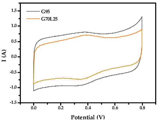
Figure 5.
Cyclic voltammetry at 5 mV/s of G95 electrode and G70L25 electrode in 1 M H2SO4.
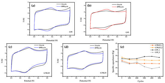
Figure 6.
Cyclic voltammetry at 20 mV/s (a) specific capacitance decreased after 4990 cycles for the electrode of G95 in 1M H2SO4; (b) specific capacitance increased after 4990 cycles for the electrode of G95 in 1 M H2SO4; (c,d) specific capacitance decreased after 4990 cycles for the electrodes of G70L25 in 1 M H2SO4; (e) the plot of specific capacitance verse cycle at 20 mV/s in H2SO4.
Figure 6 shows a CV curve measured for 4990 cycles by increasing the scan rate to 20 mV/s. Figure 6a,b is the CV curve of the G95 electrode. The specific capacitance is 62.23 F/g at 11 cycles and 61.38 F/g at 4990 cycles. The reduction of 1.38% can be seen in Figure 6a. On the other hand, specific capacitance is 57.07 F/g at 11 cycles and 59.81 F/g at 4990 cycles, which means an increase of the specific capacitance (Figure 6b). However, Figure 6c,d shows a CV curve of the G70L25 electrode. In Figure 6c, the specific capacitance was 47.37 F/g at 11 cycles and 45.94 F/g at 4990 cycles, so it decreased by 3.01%. In Figure 6d, specific capacitance is 50.98 F/g at 11 cycles and 48.41 F/g at 4990 cycles. For the G70L25 electrode, after 4990 cycles, the performance of the G70L25 electrode is consistent for several data sets, and up to 7% reduction can be expected.
The results of the G95 electrode, however, show that it is difficult to expect a reproducibility of the experiments because specific capacitance tends to both increase or decrease, which means that we cannot guarantee some level of the supercapacitor capacity after long term operation. However, all of the G70L25 electrodes tend to decrease. Therefore, even though the specific capacitance of the electrode G70L25 with the perovskite LSMCO added onto graphene nanoplatelets is lower than that of the G95 electrode, the stability seems to be superior.
3.6. Galvanostatic Charge–Discharge (GCD)
The specific capacitance of the electrodes obtained from GCD curves is calculated at various current densities by the following equation [37]:
I is a discharge current (A), is a discharge time (s), m is an active material mass, and is a potential drop during discharge.
Specific capacitance values of G95 and G70L25 for each current density are shown in Table 1. The specific capacitances of both the G95 and G70L25 electrodes were similar to those of the CV experiments. When the current density increased from 0.5 to 20 A/g, specific ion diffusion rates tended to reduce specific capacities of the G95 and G70L25 electrodes at a high current density [38]. As a result, the variation of the specific capacitance of the G95 and G70L25 electrodes over current density shows the typical behavior of a supercapacitor. The low value of capacitance at a high current density is due to the low ion penetration on the electrode surface [39]. The Ragone plot of G95 and G70L25 is shown in Figure 7d. For the G95 and G70L25 electrodes, the energy density is 21.80–16.24 Wh/kg and 17.10–15.12 Wh/kg at the same range of current density, respectively. The G70L25 electrode shows a 22% decrease in energy density at 0.5 A/g, but only a 7% decrease at 20 A/g compared to G95, which means catalytic effects of the perovskite enhances at a higher current density. In addition, we fabricated composite electrodes of LSMCO and graphene nanoplatelets by mixing and dispersing using magnetic bars and ultrasonic. In this process, we believe that structural stability increases because graphene nanoplatelets wrap around LSMCO [40].

Table 1.
The specific capacitance of G95 and G70L25 according to current density.

Figure 7.
Galvanostatic charge-discharge graph of (a) G95 electrode and (b) G70L25 electrode; (c) specific capacitance variation of G95 and G70L25 with current density; (d) comparative Ragone plots of the G95 and G70L25 electrodes.
3.7. Electrochemical Impedance Spectroscopy (EIS)
EIS is an excellent technique to investigate the electrochemical behaviors of electrodes. Figure 8 shows the replotted typical Nyquist diagram of the G95 and G70L25 electrodes. The Nyquist plot is generally composed of three parts: the first part in the high-frequency region is x-interference at the semicircle start point, which is considered as an effective ohmic resistance; the second part is a semicircular shape in the mid-frequency region, which is assumed to be a charged transfer resistance (Rct) and is equal to the diameter of the semicircle; the last part is a vertical line at the low-frequency region, which is assumed to be ion transport of diffusion resistance at the electrode/electrolyte interface [41]. In both electrodes, diffusion resistance is similar due to the same electrolyte being used. However, Rct of two electrodes is slightly different. The G70L25 electrode showed slightly larger Rct due to the additional 25 wt% LSMCO causing a decrease of the diffusion pathway accompanied by the reduction in surface area, as shown in Figure 3. The steeper slope of the G95 can explain the higher initial specific capacitance in the CV experiment because it means a faster diffusion.

Figure 8.
Impedance spectra of the G95 and G70L25 electrodes, measured at an AC amplitude of 10 mV, in H2SO4 electrolyte.
The G70L25 electrode exhibits increasing ohmic resistance, which may originate from the low electrical conductivity of LSMCO perovskite oxide.
4. Conclusions
In summary, the supercapacitor electrode was prepared by the synthesis of graphene and perovskite material (LSMCO). XRD showed that it was well mixed without a secondary reaction. According to electrochemical analyses, for the G95 electrode, the specific capacitance ranges from 53 to 68 F/g, and the standard deviation is about 6. For the G70L25 electrode, the specific capacitance ranges from 49 to 55 F/g, and the standard deviation ranges from 1 to 2.5. The initial specific capacity of the G70L25 electrode of 49 to 55 F/g is about 10%–20% smaller than that of the G95 but has a small standard deviation. The cycling test showed that the specific capacitance of G70L25 was reduced (~5%) at all times, indicating that the cycling stability was improved compared to the unpredictable (both cases increasing or decreasing) results of G95. Therefore, the supercapacitor using LSMCO and graphene electrode is better for commercialization considering the repeatable performance and seems to be an excellent material for improving cycling stability in other electrochemical applications.
Author Contributions
Conceptualization, Y.-W.J. and J.S.; data curation, B.-M.K. and H.-Y.K.; investigation, B.-M.K. and H.-Y.K.; methodology, J.S.; supervision, Y.-W.J. and J.S.; validation, B.-M.K., H.-Y.K., Y.-W.J., and J.S.; visualization, B.-M.K. and H.-Y.K.; writing – original draft, B.-M.K.; writing – review and editing, Y.-W.J. and J.S. All authors have read and agreed to the published version of the manuscript.
Funding
This research was supported by the Basic Science Research Program through the National Research Foundation of Korea (NRF), funded by the Ministry of Education (No. NRF-2018R1D1A1A02085324). This research was supported by the Mid-Career Researcher Program (No. NRF-2020R1A2C1007847) through the National Research Foundation of Korea, funded by the Korean government’s Ministry of Education.
Conflicts of Interest
The authors declare no conflicts of interest.
References
- Simon, P.; Gogotsi, Y. Materials for electrochemical capacitors. Nat. Mater. 2008, 7, 845–854. [Google Scholar] [CrossRef]
- Obreja, V.V.N. On the performance of supercapacitors with electrodes based on carbon nanotubes and carbon activated material—A review. Phys. E Low Dimens. Syst. Nanostruct. 2008, 40, 2596–2605. [Google Scholar] [CrossRef]
- Conway, B.E. Electrochemical Supercapacitors: Scientific Fundamentals and Technological Applications; Springer Science & Business Media, LLC: New York, NY, USA, 2013. [Google Scholar]
- Augustyn, V.; Simon, P.; Dunn, B. Pseudocapacitive oxide materials for high-rate electrochemical energy storage. Energ. Environ. Sci. 2014, 5. [Google Scholar] [CrossRef]
- Guidelli, R.; Schmickler, W. Electrosorption valency and partial charge transfer. Mod. Asp. Electrochem. 2005, 38, 303–371. [Google Scholar]
- Herrero, E.; Buller, L.J.; Abruña, H.D. Underpotential deposition at single crystal surfaces of Au, Pt, Ag and other materials. Chem. Rev. 2001, 101, 1897–1930. [Google Scholar] [CrossRef] [PubMed]
- Zheng, J.P. A new charge storage mechanism for electrochemical capacitors. J. Electrochem. Soc. 1995, 142, L6. [Google Scholar] [CrossRef]
- Augustyn, V.; Come, J.; Lowe, M.A.; Kim, J.W.; Taberna, P.L.; Tolbert, S.H.; Abruña, H.D.; Simon, P.; Dunn, B. High-rate electrochemical energy storage through Li + intercalation pseudocapacitance. Nat. Mater. 2013, 12, 518–522. [Google Scholar] [CrossRef]
- Brezesinski, T.; Wang, J.; Tolbert, S.H.; Dunn, B. Ordered mesoporous α-MoO3 with iso-oriented nanocrystalline walls for thin-film pseudocapacitors. Nat. Mater. 2010, 9, 146–151. [Google Scholar] [CrossRef]
- Bai, L.; Ge, Y.; Bai, L. Boron and Nitrogen co-doped porous carbons synthesized from polybenzoxazines for high-performance supercapacitors. Coatings 2019, 9, 657. [Google Scholar] [CrossRef]
- Heydari Gharahcheshmeh, M.; Gleason, K.K. Device fabrication based on oxidative chemical vapor deposition (CVD) synthesis of conducting polymers and related conjugated organic materials. Adv. Mater. Interfaces 2019, 6, 1801564. [Google Scholar] [CrossRef]
- Feng, N.; Meng, R.; Zu, L.; Feng, Y.; Peng, C.; Huang, J.; Liu, G.; Chen, B.; Yang, J. A polymer-direct-intercalation strategy for MoS 2/carbon-derived heteroaerogels with ultrahigh pseudocapacitance. Nat. Commun. 2019, 10, 1–11. [Google Scholar] [CrossRef]
- Cao, M.S.; Wang, X.X.; Cao, W.Q.; Yuan, J. Ultrathin graphene: Electrical properties and highly efficient electromagnetic interference shielding. J. Mater. Chem. C 2015, 3, 6589–6599. [Google Scholar] [CrossRef]
- Ji, X.; Xu, Y.; Zhang, W.; Cui, L.; Liu, J. Review of functionalization, structure and properties of graphene/polymer composite fibers. Compos. Part A Appl. Sci. Manuf. 2016, 87, 29–45. [Google Scholar] [CrossRef]
- Wang, J.; Li, Z.; Fan, G.; Pan, H.; Chen, Z.; Zhang, D. Reinforcement with graphene nanosheets in aluminum matrix composites. Scr. Mater. 2012, 66, 594–597. [Google Scholar] [CrossRef]
- Zhai, W.; Shi, X.; Wang, M.; Xu, Z.; Yao, J.; Song, S.; Wang, Y.; Zhang, Q. Effect of graphene nanoplate addition on the tribological performance of Ni3Al matrix composites. J. Comp. Mater. 2013, 48, 3727–3733. [Google Scholar] [CrossRef]
- Ruiz, V.; Santamaría, R.; Granda, M.; Blanco, C. Long-term cycling of carbon-based supercapacitors in aqueous media. Electrochim. Acta 2009, 54, 4481–4486. [Google Scholar] [CrossRef]
- Yan, J.; Wei, T.; Fan, Z.; Qian, W.; Zhang, M.; Shen, X.; Wei, F. Preparation of graphene nanosheet/carbon nanotube/polyaniline composite as electrode material for supercapacitors. J. Power Sources 2010, 195, 3041–3045. [Google Scholar] [CrossRef]
- Sengodan, S.; Choi, S.; Jun, A.; Shin, T.H.; Ju, Y.W.; Jeong, H.Y.; Shin, J.; Irvine, J.T.S.; Kim, G. Layered oxygen-deficient double perovskite as an efficient and stable anode for direct hydrocarbon solid oxide fuel cells. Nat. Mater. 2015, 14, 205–209. [Google Scholar] [CrossRef]
- Kim, S.; Kwon, O.; Kim, C.; Gwon, O.; Jeong, H.Y.; Kim, K.H.; Shin, J.; Kim, G. Strategy for enhancing interfacial effect of bifunctional electrocatalyst: Infiltration of cobalt nanooxide on perovskite. Adv. Mater. Interfaces 2018, 5, 1800123. [Google Scholar] [CrossRef]
- Gwon, O.; Kim, C.; Kwon, O.; Jeong, H.Y.; Park, H.-K.; Shin, J.; Ju, Y.-W.; Kim, G. An efficient oxygen evolution catalyst for hybrid lithium air batteries: Almond stick type composite of perovskite and cobalt oxide. J. Electrochem. Soc. 2016, 163, A1893–A1897. [Google Scholar] [CrossRef]
- Ishihara, T. Perovskite Oxide for Solid Oxide Fuel Cells; Springer Science & Business Media: Berlin, Germany, 2009. [Google Scholar]
- Mefford, J.T.; Hardin, W.G.; Dai, S.; Johnston, K.P.; Stevenson, K.J. Anion charge storage through oxygen intercalation in LaMnO 3 perovskite pseudocapacitor electrodes. Nat. Mater. 2014, 13, 726–732. [Google Scholar] [CrossRef] [PubMed]
- Wohlfahrt-Mehrens, M.; Schenk, J.; Wilde, P.M.; Abdelmula, E.; Axmann, P.; Garche, J. New materials for supercapacitors. J. Power Sources 2002, 105, 182–188. [Google Scholar] [CrossRef]
- Lim, C.; Kim, C.; Gwon, O.; Jeong, H.Y.; Song, H.K.; Ju, Y.W.; Shin, J.; Kim, G. Nano-perovskite oxide prepared via inverse microemulsion mediated synthesis for catalyst of lithium-air batteries. Electrochim. Acta 2018, 275, 248–255. [Google Scholar] [CrossRef]
- Liu, Y.; Dinh, J.; Tade, M.O.; Shao, Z. Design of perovskite oxides as anion-intercalation-type electrodes for supercapacitors: Cation leaching effect. ACS Appl. Mater. Interfaces 2016, 8, 23774–23783. [Google Scholar] [CrossRef] [PubMed]
- Saranya, P.; Selladurai, S. Facile synthesis of NiSnO 3/graphene nanocomposite for high-performance electrode towards asymmetric supercapacitor device. J. Mater. Sci. 2018, 53, 16022–16046. [Google Scholar] [CrossRef]
- He, L.; Shu, Y.; Li, W.; Liu, M. Preparation of La 0.7 Sr 0.3 CoO 3-δ (LSC)@ MnO 2 core/shell nanorods as high-performance electrode materials for supercapacitors. J. Mater. Sci. Mater. Electron. 2019, 30, 17–25. [Google Scholar] [CrossRef]
- Yin, S.; Wu, Y.; Chen, J.; Chen, Z.; Hou, H.; Liu, Q.; Wang, Y.; Zhang, W. Facile hydrothermal synthesis of BiFeO3 nanoplates for enhanced supercapacitor properties. Funct. Mater. Lett. 2018, 11, 1850013. [Google Scholar] [CrossRef]
- George, G.; Jackson, S.L.; Luo, C.Q.; Fang, D.; Luo, D.; Hu, D.; Wen, J.; Luo, Z. Effect of doping on the performance of high-crystalline SrMnO3 perovskite nanofibers as a supercapacitor electrode. Ceramics Int. 2018, 44, 21982–21992. [Google Scholar] [CrossRef]
- Kim, H.-Y.; Shin, J.; Jang, I.-C.; Ju, Y.-W. Hydrothermal synthesis of three-dimensional perovskite NiMnO3 oxide and application in supercapacitor electrode. Energies 2020, 13, 36. [Google Scholar] [CrossRef]
- Lang, X.; Mo, H.; Hu, X.; Tian, H. Supercapacitor performance of perovskite La1−xSrxMnO3. Dalton Trans. 2017, 46, 13720–13730. [Google Scholar] [CrossRef]
- Wei, R.; Fang, M.; Dong, G.; Ho, J.C. Is platinum a suitable counter electrode material for electrochemical hydrogen evolution reaction? Sci. Bull. 2017, 62, 971–973. [Google Scholar] [CrossRef]
- Gardner, S.D.; Singamsetty, C.S.K.; Booth, G.L.; He, G.R.; Pittman, C.U. Surface characterization of carbon fibers using angle-resolved XPS and ISS. Carbon 1995, 33, 587–595. [Google Scholar] [CrossRef]
- Arrigo, R.; Hävecker, M.; Wrabetz, S.; Blume, R.; Lerch, M.; McGregor, J.; Parrott, E.P.J.; Zeitler, J.A.; Gladden, L.F.; Knop-Gericke, A.; et al. Tuning the acid/base properties of nanocarbons by functionalization via amination. J. Am. Chem. Soc. 2010, 132, 9616–9630. [Google Scholar] [CrossRef] [PubMed]
- Liu, W.W.; Yan, X.B.; Xue, Q.J. Multilayer hybrid films consisting of alternating graphene and titanium dioxide for high-performance supercapacitors. J. Mater. Chem. C 2013, 1, 1413–1422. [Google Scholar] [CrossRef]
- Dezfuli, A.S.; Ganjali, M.R.; Naderi, H.R.; Norouzi, P. A high performance supercapacitor based on a ceria/graphene nanocomposite synthesized by a facile sonochemical method. RSC Adv. 2015, 5, 46050–46058. [Google Scholar] [CrossRef]
- Zhang, C.; Lei, C.; Cen, C.; Tang, S.; Deng, M.; Li, Y.; Du, Y. Interface polarization matters: Enhancing supercapacitor performance of spinel NiCo2O4 nanowires by reduced graphene oxide coating. Electrochim. Acta 2018, 260, 814–822. [Google Scholar] [CrossRef]
- Szunerits, S.; Boukherroub, R. Electrochemistry of graphene: The current state of the art. Electrochemistry 2013, 12, 211–242. [Google Scholar]
- Kim, C.; Gwon, O.; Jeon, I.-Y.; Kim, Y.; Shin, J.; Ju, Y.-W.; Baek, J.-B.; Kim, G. Cloud-like graphene nanoplatelets on Nd 0.5 Sr 0.5 CoO 3− δ nanorods as an efficient bifunctional electrocatalyst for hybrid Li–air batteries. J. Mater. Chem. A 2016, 4, 2122–2127. [Google Scholar] [CrossRef]
- Mei, B.A.; Munteshari, O.; Lau, J.; Dunn, B.; Pilon, L. Physical interpretations of Nyquist plots for EDLC Electrodes and Devices. J. Phys. Chem. C 2018, 122, 194–206. [Google Scholar] [CrossRef]
© 2020 by the authors. Licensee MDPI, Basel, Switzerland. This article is an open access article distributed under the terms and conditions of the Creative Commons Attribution (CC BY) license (http://creativecommons.org/licenses/by/4.0/).