Abstract
This paper focuses on the design of an optimized thermal interface for a thermoelectric energy harvesting system mounted at endothermic animals. In this application scenario the mammal’s fur reduces the heat flux from the animal’s body through a thermoelectric generator (TEG) to the ambient air. This requires an adapted design of the thermal interface between TEG and body surface, to increase its thermal conductivity without harming the animal. For this purpose the thermal conductivity through a mammal’s fur is determined with a specially designed heatsink. An analytical model is built to predict the resulting thermal resistances and is validated with experimental results for two different fur lengths. We show that an optimized design of the thermal interface reduces its thermal resistance up to 38% compared to a trivial design while lowering its weight for about 23%. It is found that the most important design parameter of such a thermal connector is the ability to slide into the fur.
1. Introduction
With the ongoing reduction of power consumption for sensor systems, energy harvesting (EH) techniques have become more popular in application fields like wildlife monitoring. Mobile trackers, attached to the desired animal, are used to gather important data about the host’s habits and health status. Commercially available trackers such as the LifeTag™ [1] already use energy harvesting techniques such as solar cells to prolong battery lifetime. Thermoelectric systems, harvesting energy from the temperature difference between host and environment, can be a more robust alternative with a more continuous energy income. However, in previous field experiments at sheep, a temperature difference of only 2.5 to 3.5 was achieved between the surface of the animal’s fur and the ambient air. With a reasonably sized thermoelectric generator (TEG)-air energy harvesting system the possible energy outcome in the range of 54 [2] is correspondingly low. This is a major issue for a typical wildlife tracking system that has to gather the position of the animal regularly. The global positioning system (GPS) commonly used for that task draws about 320 of power in active mode for a longer period of time (sometimes more than 30 ) [3]. This is not only a problem for energy harvesting systems, as it usually exceeds the energy incomes of those, but even in battery driven applications the power consumption of GPS heavily restricts the amount of positions that can be gathered when a long lifetime without changing batteries is desired.
An improvement of the energy income is challenging, as this normally means, for a thermoelectric EH system, an increased heat flux from the animal body into the TEG, and from there to the ambient air. Increasing the heat flux by using a TEG with larger area is only possible to some extent, as the growing weight and size restricts the attachment of arbitrary large devices. Thermal energy harvesting devices that are attached to human skin exist [4,5]. Design parameters to improve thermal conductivity and weight are present in this case, but this knowledge is not applicable for devices harvesting through the thick or thin fur of a mammal. A great difference is the significant lower thermal conductivity of fur compared to human skin. In addition to that, an optimized design of a thermal heat connector (THC) for animal fur will deviate from one made for bare skin. Although rough values for the fur’s thermal conductivity can be obtained from existing literature [6,7,8,9], it is unclear how THCs should be designed to lower the resulting thermal resistance. In the first part of this paper, we explain the analytical model developed for an optimal design of a THC. Based on the findings from the model, several optimized THCs are fabricated. The following chapters concentrate on the experiment, which evaluates these designs in terms of thermal resistance, weight and penetration capability into the fur. Finally, we will compare the results of the experiment with the values expected from the model.
2. General Consideration for a Thermoelectric Energy Harvesting System Operated on an Animal
We focus on a thermoelectric energy harvesting system attached to an endothermic animal using the temperature difference between its host and the environment. Such a system can be described by an equivalent model with five simplified components, as shown in Figure 1. The animal is modeled as an inexhaustible heat source with an almost constant temperature . The fur and skin, together with a thermal heat connector to the TEG provide a first thermal resistance in the heat path between the animal’s core temperature and the environment. Two additional thermal resistances are formed by the TEG itself and a heatsink mounted on top, which connects the system to the ambient air temperature .
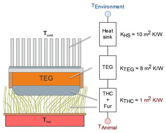
Figure 1.
Equivalent circuit model for a thermoelectric harvesting system attached to an animal. In typical scenarios, the thermal conductivity of the fur is significantly poorer than for the other samples.
In our case, it is desired to maximize the output power of the TEG in such a system. Literature exists that describes the impacts of the thermal impedances, overall temperature difference and properties of the TEG on the output power thoroughly [10]. The choice of an appropriate TEG is critical for a good performance, but usually is a compromise between its thermal and electrical resistance as well as output voltage. A major challenge when only low temperature gradients are available for harvesting is the corresponding low output voltage of the TEG. With only a total temperature difference of about 10 between the environment and the animal, the TEG’s output voltage will be in the range of a few millivolts when optimizing for power output. This commonly leads to a poor usable electric power, considering that a necessary up-conversion of the TEG’s output voltage to drive an attached electronic system is associated with high losses. It is therefore possible that a system focusing on a high TEG output voltage can deliver an overall higher usable power than one trying to solely optimize the power outcome of the TEG. Regarding the thermal impedance of the TEG, the user is frequently bound to TEGs of relatively high thermal conductivity which forces him to thermally adopt the heatsink and thermal heat connector.
An exemplary situation is described in the literature for energy harvesting from human body heat [5]. However, the main difference to highlight when harvesting from an animal is the lower thermal conductivity at the skin side. While the thermal resistivity of the human skin is around 0.05 m K/W [11], the corresponding value for an animal with a fur length of only 5 is between 1.25 and 0.33 m K/W [7]; i.e., much higher. As a result, the THC is the part with the largest potential of improvement in the chain of thermal resistances (see Figure 1) and has a great impact on the overall performance. One strategy could be to increase the size of a THC, thereby reducing its thermal resistance through an increased contact area. This approach is, however, not viable for two reasons: First, animal ethics dictate a maximum weight of, e.g., a collar below 6% of the animal’s body mass [12]. In general, a minimal footprint and weight for systems attached to an animal are desired to lower the impact on the animal. Second, a THC with a large thermal mass will act as a thermal low pass filter in time. This means that rapid thermal transients are averaged and the temperature difference across the TEG is averaged in the same way. As a result, the thermal power and electrical power available, which is proportional to the square of the temperature difference, is reduced. It is therefore the aim of this study to find a design of a THC with a reasonable compromise of all these boundary conditions [13].
3. THC Design
The design of the THC is based on a typical heat sink made from aluminum; see Figure 2. The fins of this heatsink are cylindrical, as they should penetrate the fur of the animal. The idea is to reduce the overall thermal resistance of the fur by having a short-circuit thermal path through the fur, along a material with a much lower thermal resistance, here the fins.
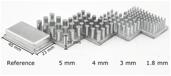
Figure 2.
Photograph of the five different versions of the thermal heat connector (THC), here for sheep’s wool, with variations in fin diameter and spacing. The fins height is 10 for the experiment with the sheep wool and 3 for the goat fur.
When attaching the THC to the animal, the corresponding thermal path will split into three different sections: One part of the fur will be pushed between the fins and slightly compressed. The other part of the fur will be compressed between the animal’s skin and the fins.
This scenario can be modeled with an equivalent circuit, as clarified in Figure 3. We assume that sliding the THC into the fur does not have an impact on the fur’s thermal conductivity. Instead we consider that the fur evenly slides aside and fills the space between the cylindrical fins. With respect to that, the thermal path through the fins and through the fur to the rest of the harvesting system is of the same length . Typically the THC will not be able to reach to the skin of the animal and a certain layer (thickness ) of fur stays in between. Considering the animal as an inexhaustible heat source and neglecting other thermal resistances on the cold side, the constellation of mixed fur and fins can be expressed as two thermal resistances placed in parallel to each other. The remaining fur beneath adds a high resistance in series to that parallel circuit.
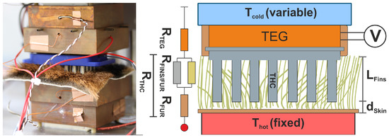
Figure 3.
Left: Experimental set-up with the test device (THC and fur sample) put between two temperature-controlled plates. The THC with a fin length of 10 was used with the short fur for demonstration purposes. Right: Schematic and equivalent circuit of the THC at the fur. The fins of the THC act as a parallel thermal resistance to the thermal resistance of the displaced fur. The remaining fur between THC and skin is represented as a thermal resistance in series.
With the help of this equivalent circuit, the total combined resistance of fur and THC can be described by Equation (2) where is the fin length and the thickness of the fur that remains below the THC. The size of the THC and therefore the total area of harvesting is split into and . corresponds to the total front face of the fins, whereas relates to the area in between where only fur is present. The two thermal resistivity values are for the fur and for the material of the fins.
For a single thermal resistance , Equation (1) is used to describe its value as a function of the thermal conductivity of its material (k), its surface area (A) and the length of the heat path through the resistance (L):
Using standard equations for the parallel and serial electrical circuit of resistors, the following Equation (2) holds for the combination of the fur and THC:
It is worth mentioning that the parameter for aluminum of 237 / is four to five orders of magnitude greater than with 0.04–0.15 W/(mK). For that reason, the first term of Equation (2) is small even with a tiny face area . As a result, the overall resistance is determined by the second fraction. Decreasing the second part of the equation can be done by two options: either by minimizing , the distance between the fins and the bare skin, or by increasing the fins’ amount () of the total harvesting area . A third option, increasing the total harvesting area itself, is normally not desired. In the real world, and can not be optimized without affecting each other in a negative manner. For example, a dominating would on one hand decrease the thermal resistance, but would compress a lot of fur beneath the fins on the other, thereby increasing the overall distance to the skin. Care must be taken that there is enough room for the fur to slide in between the fins to not negatively affect . Accordingly, the fin diameter and spacing between the fins need to be reasonable.
The resulting distance to the skin will be also affected by the length of the fins. A high length allows the fins to get closer to the skin, as the bottom part of the THC will not compress the fur beneath. However the length can not be arbitrarily high. The fins have to be long enough to penetrate deep enough into the fur, but any additional length would leave space between the fur’s surface and the THC’s bottom. This gap is detrimental in its effect, as it will provide a path for heat dissipation to the surrounding air, bypassing the heat flux through the TEG.
Therefore, an appropriate THC design should focus on the penetration capability when typical materials with high thermal conductivity are used for the THC itself. The penetration capability is expected to be dependent on the shape of the fins. Rounded or pointed cylinders have a greater chance to push the fur aside, whereas fins with a flat top more likely compress the fur beneath. In addition to that, the diameter and spacing of the fins has to be taken into account: While larger diameters would be desirable in order not to harm the animal’s skin, their larger front area tends to compress the animals’ fur to a higher degree. This will increase the thermal resistance as a detrimental effect. Besides that, it is always possible to lower the overall resistance via a greater harvesting area with the disadvantage of a larger weight and size of the THC.
For our experimental setup, we are using only designs with fully cylindrical fins which may not be the optimal shape with the best penetration capability, but are taken here due to a simpler manufacturing process. As the new design is compared to a trivial design, here an aluminum plate with a planar surface (see Figure 2), it is still possible to derive whether the penetration capability has an impact on the overall resistance.
4. Experimental Setup
An experimental setup was built to verify the validity of the developed model and to get an approximate value of the thermal resistance for each of five different THC designs. To cover a wide range of fur types, we adopted the THC designs for two extreme cases: The first set was designed for an animal with long and thick fur, whereas the second set is representative of animals with very short fur. It can be expected that the behavior of other animal fur lies in between the gathered results. Due to regulations and market availability, the wool of a merino sheep was taken for the long-fur set, while the fur of a domestic goat was used for the short-fur set.
Each of the two sets consist of four different THCs which differ in the diameter of the fins and in the space in between. They are named according to their fin diameter, as shown in Figure 2. The length of the fins in each set corresponds to the fur length it was made for. For the set intended for the sheep fur, an equal fin length of 10 was chosen. The fin length for the set with the goat fur was 3 . A photo of the fabricated THCs is shown in Figure 2.
The basic setup for the experiment is shown in Figure 3: The THC is put into a housing together with the TEG that is used to determine the thermal flux. This device is then placed between a hot plate with a fixed temperature, covered by a piece of fur, and a temperature-controlled cold plate in close contact with the TEG. The test device is pressed gently into the fur by the upper plate, as demonstrated in Figure 3. The temperature of the bottom plate is fixed to 33 , based on temperature measurements at the skin of a sheep in [9]. The upper plate’s temperature is varied between 20 and 30 , resulting in a total temperature gradient of 3–12 K. The measurements were taken in a temperature controlled room at 21 and a relative humidity of 60%.
After each adjustment of the temperature, 20 min of waiting was considered before the output voltage of the TEG was measured. The temperature gradient at the TEG can be derived from the measured voltage and the known Seebeck coefficient . is linear correlated to the applied according to Equation (3):
The slope m in Equation (3) is related to the thermal resistance of the THC-fur combination and TEG as given in Equation (4). The desired resistance can be therefore determined from the slope m recorded in the experiment, according to:
The parameter c in Equation (3) is neglected in our setup as it is caused by parasitic heat flux of the surroundings and not through the TEG. In an optimal setup, c would be zero. Finally, the penetration capability of the THC is roughly estimated by gently pushing it into the fur. This is done with a force of 300 g weight and moving the THC back and forth a few millimeters. It is then observed how the fur is compressed or slides away. The details of the used TEG and the data of the fur are stated in Table 1. All other used components and the corresponding results are finally summarized in Table 2.

Table 2.
Summary of the parameters determined and used in the experiment.
Table 1.
Relevant parameters that are used in the experimental set-up. For design parameters of the THCs see Figure 4.
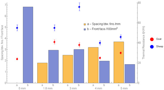
Figure 4.
Measured thermal resistances of the goat (red) and sheep (blue), together with the corresponding fin spacing (a) and front face (b) of the used thermal heat connectors together with their fin diameters.
Table 1.
Relevant parameters that are used in the experimental set-up. For design parameters of the THCs see Figure 4.
| Data of TEG (TEG-083-230-07, Thermalforce) | Data of Fur | |||
|---|---|---|---|---|
| Thermal Resistance | / | Animal | Fur length | Fin length |
| Thermal Conductivity | / | Merino sheep | 30–70 | 10 |
| Seebeck-Coefficient | 23.4 ± 0.4 mV/K | Domestic goat | 20–30 | 3 |
5. Experimental Results and Discussion
Both measurement series, with the fur of the sheep and goat, show the expected linear correlation between the temperature difference across the setup and the temperature difference at the TEG. Figure 5a,b reveals the measured points and the calculated slopes, with a linear regression fit.
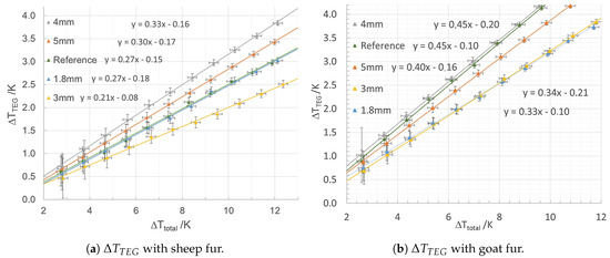
Figure 5.
at the TEG for the set of THCs as a function of the temperature gradient between the animal’s fur and the environment. From the slope of the linear fits, the resulting thermal resistance of the THC can be calculated.
A higher slope m of the linear fit corresponds to a reduced thermal resistance of the THC which can be finally calculated with an adjusted form of Equation (4). The resulting thermal resistances are summarized in Figure 4 with additional details in Table 2.
It can be seen that all THCs which are used in the goat’s fur with a length between 20 and 30 in general have a smaller thermal resistance than those of the sheep’s longer wool with 30 to 70 length. This is in agreement with our expectation that the longer fur has better isolation capabilities.
The results at the sheep’s fur show that the lowest overall thermal resistance is not achieved with the THC with the smallest fin diameter of , but with the one with 4 . This THC achieves a 38% lower thermal resistance than the reference design while having only 65% of its weight. Indeed, the THC with a fin’s diameter of 4 has large spacing between the fins compared to those with a smaller fin diameter.
The goat’s fur differs from the sheep’s wool. The adapted THC designs mostly show a higher or similar thermal resistance than the reference. The THC with a fin diameter of 4 performs as good as the reference, while having a lower weight compared to the reference. It is reasonable to suppose that the thermal path cannot be improved as much as this is possible in the case of a long fur and fin length.
Two results of the experiment are worth being pointed out. First, the THC with a fin diameter of 1.8 mm performs bad at both fur lengths, despite having the smallest fin diameter. A possible explanation is the THC’s minimal space between the fins among all the tested ones. Second, the THC with a fin diameter of 3 in the sheep’s fur has a remarkably higher thermal resistance compared to the other. This could be an indication that the results may have been influenced by parameters that have not been recorded, like slight variations in the force that is applied to the TEG-THC combination.
Besides the fin diameter and spacing between the fins, an important parameter is the capability of a THC to slide into the fur, summarized with the other parameters in Table 2. It can be seen that a good sliding into the sheep’s wool is observed for the 4 diameter THC. Here, the major part of the fur slides between the fins and is not compressed beneath. This could be due to the fact that this THC has the second highest spacing between the fins and exhibits a small total front face area. Despite this small contact area, the 4 THC works best at both fur lengths. It is worth mentioning that the lateral fin spacing and front surface of the 4 and 5 THCs are similar, but the resulting thermal resistances differ significantly. This could be an indication for the importance of the penetration capability, as the 5 diameter fins are not able to appropriately displace the fur; they instead compress it beneath. Other fin designs may behave differently; e.g., a rounded shape on top of the fin.
To check the results for plausibility, we derive the theoretical distance between fur and fins from Equation (2). The thermal resistance is directly taken from the measured results, whereas we define , as 0.1 ± 0.04 W/(mK) taken from [6] as an estimation for the fur’s thermal resistivity. The thermal resistance of the THC, is fixed to 237 /. It is reasonable to expect that the calculated for each THC should be in the range of only a few . Table 3 indeed states that the corresponding is reasonable, but its improvement from 5 of the reference down to a of 3.7 mm for an optimized THC at the sheep is too small compared to the fin length of 10 . An improved setup could reveal here more about the influence of the fin length and applied force on the THC and the corresponding compression of the fur beneath.
Table 3.
Computed distance between fins and skin of the animal with Equation (2). The distance was calculated from the measured thermal resistance and a the theoretic value of and .
In general, the difference of the thermal resistance between reference and optimized THC is greater for the long fur than it is for the short which we trace back to the longer thermal path that can be optimized at longer fur lengths. The measurement of the fur’s thermal resistance is challenging, as it is dependent on various parameters like humidity, fur length and type. In addition to that the THC itself has various design parameters, of which the penetration capability especially cannot be accurately determined. A relative comparison, as done in this paper, between several THC designs circumvents a lot of the mentioned errors. The gathered thermal resistances of the THC are in the expected range, which is calculated as 81 to 22 / for a length mm of the goat fur. For the sheep fur with a length at mm the measured thermal resistance is below our expectation of 72 to 272 /. In the experiments, a value between 40 and 72 / was found. This could be an indication for an overestimated fur length and thereby in the setup.
Overall, the experiment demonstrates that a THC design with fins can lower the overall thermal resistance by up to 38% as well as reduce the weight in comparison to a planar bulk design. According to Equation (2), the diameter of the fins should not play a significant role. Instead, the remaining fur between the tip of the fins and the skin will dominate the total thermal resistance of the interface. The experiments are in accordance to that assumption as they do not show a clear trend of thermal resistance dependency on the fin diameter. Additionally, the results do not give a clear indication that the spacing between the fins has a great impact. Both of them, however, have an impact on the ability of the THC to penetrate the fur which correlates to the thermal resistance. We assume that a good penetration capability would bring the THC closer to the skin, reducing in Equation (2).
6. Summary and Conclusions
We investigated improving the heat flux through a thermoelectric energy harvesting system used at endothermic animals. Consisting of a thermoelectric generator (TEG), heatsink and thermal heat connectors (THC), we found that the THC offers the largest potential for an improved heat flux and therefore power outcome of such a system. A new and adopted design for a THC was developed, based on that of a typical heatsink with cylindrical fins, aiming to improve the heat flux while maintaining minimal weight and dimensions. Concerning the thermal resistance of the THC, our derived mathematical model states that a good design should have fins that get as close as possible to the animal’s skin. The fin diameter itself plays only a minor role according to the model equations developed in this research.
We have then verified the results predicted by the model in an experiment. Different designs of THCs were fabricated and their thermal resistances were determined with the fur of a long and short haired animals, respectively. The experiments reveal that one major influence factor on the thermal resistance is only indirectly covered by the formulated model equation: the penetration capability of the THC design is highly dependent on shape and width of the fins, and on the spacing in between. While fins with smaller diameters slide better into the fur, a large enough spacing between the fins becomes more important to give the fur room for mingling with the THC and to get as close as possible to the skin. The 4 pile diameter design of the THCs has achieved a thermal resistance that is 38% better than the reference design and has less weight compared to the same.
As far as we know, this is the first time that the thermal resistance of fur with an attached heat connector has been examined. The results can be seen as a starting point toward obtaining THCs with lower weight and improved heat flux. Besides the results of this paper showing that the penetration capability is one important parameter, other environmental effects like humidity or differences in the structure of the fur may heavily influence the overall thermal resistance of the connection between the animal and device. Field experiments to reveal such effects are on the way and may help in simulating such a device.
The outcome can be useful for energy-autonomous animal tracking systems that are put on an endothermic animal to harvest energy directly from their hosts. With the chance of an improved energy income or smaller size, this could be used to prolong battery lifetime or solely run the system from harvested energy. A reduced weight will also allow the user to attach these systems to smaller animals where the maximum allowed 6% of the body weight is restricting thermal harvesting. In fact, a system built out of two of the proposed THCs and two corresponding heatsinks will have a weight around 120 , excluding electronics and the collar itself. This is in the range of commercially available GPS-trackers like the Vertex Plus Collar, with a total weight of at least 470 [14]. The benefit we expect from this system is, however, its longer operational lifetime, as no exhaustible energy storage is used.
Author Contributions
Conceptualization, Validation, Formal Analysis, Writing, P.W. and E.B.; Preparation, Experimental data acquisition, P.B. and E.B. All authors have read and agreed to the published version of the manuscript.
Funding
The article processing charge was funded by the Baden-Wuerttemberg Ministry of Science, Research and Art and the University of Freiburg in the funding program Open Access Publishing.
Conflicts of Interest
The authors declare no conflict of interest.
References
- LifeTag™; Cellular Tracking Technologies: Rio Grande, NJ, USA, 2019.
- Woias, P.; Schule, F.; Bäumker, E.; Mehne, P.; Kroener, M. Thermal Energy Harvesting from Wildlife. J. Phys. Conf. Ser. 2014, 557, 012084. [Google Scholar] [CrossRef]
- Kjærgaard, M.B.; Langdal, J.; Godsk, T.; Toftkjær, T. Entracked: Energy-Efficient Robust Position Tracking for Mobile Devices. In Proceedings of the 7th International Conference on Mobile Systems, Applications, and Services (MobiSys 2009), Kraków, Poland, 22–25 June 2009. [Google Scholar]
- Settaluri, K.T.; Lo, H.; Ram, R.J. Thin Thermoelectric Generator System for Body Energy Harvesting. J. Electron. Mater. 2012, 41, 984–988. [Google Scholar] [CrossRef]
- Thielen, M.; Sigrist, L.; Magno, M.; Hierold, C.; Benini, L. Human body heat for powering wearable devices: From thermal energy to application. Energy Conv. Manag. 2017, 131, 44–54. [Google Scholar] [CrossRef]
- Cena, K.; Clark, J. Heat balance and thermal resistances of sheep’s fleece. Phys. Med. Biol. 1974, 19, 51. [Google Scholar] [CrossRef]
- Cena, K.; Monteith, J.L. Transfer Processes in Animal Coats. II. Conduction and Convection. Proc. R. Soc. Lon. Ser. B Biol. Sci. 1975, 188, 395–411. [Google Scholar]
- Cena, K.; Monteith, J.L. Transfer processes in animal coats. I. Radiative transfer. Proc. R. Soc. Lon. Ser. B Biol. Sci. 1975, 188, 377–393. [Google Scholar]
- Gatenby, R.M.; Monteith, J.; Clark, J. Temperature and humidity gradients in a sheep’s fleece. I. Gradients in the steady state. Agric. Meteorol. 1983, 29, 1–10. [Google Scholar] [CrossRef]
- Spies, P.; Pollak, M.; Mateu, L. Handbook of Energy Harvesting Power Supplies and Applications; CRC Press: Boca Raton, FL, USA, 2015. [Google Scholar]
- Leonov, V.; Torfs, T.; Fiorini, P.; Van Hoof, C. Thermoelectric converters of human warmth for self-powered wireless sensor nodes. IEEE Sens. J. 2007, 7, 650–657. [Google Scholar] [CrossRef]
- Sodeikat, G.; Neubeck, K.; Schmidt, J. Verhaltensuntersuchungen an juvenilen Birkhühnern nach Anbringung von unterschiedlich schweren Halsbandsendern—Eine Pilotstudie. NNA Sonderheft 2008, 19, 43–46. [Google Scholar]
- Moser, A.; Erd, M.; Kostic, M.; Cobry, K.; Kroener, M.; Woias, P. Thermoelectric Energy Harvesting from Transient Ambient Temperature Gradients. J. Electron. Mater. 2012, 41, 1653–1661. [Google Scholar] [CrossRef]
- Vertex Plus-Datasheet; VECTRONIC Aerospace: Berlin, Germany, 2018.


© 2020 by the authors. Licensee MDPI, Basel, Switzerland. This article is an open access article distributed under the terms and conditions of the Creative Commons Attribution (CC BY) license (http://creativecommons.org/licenses/by/4.0/).