1. Introduction
Fractures are induced due to geological processes or excavation disturbances in underground engineering, and they bring great safety hazard to engineering stability [
1,
2,
3]. Grouting is a method of injecting cement, sand, bentonite, or chemical materials with water into soil or rock masses in order to decrease permeability and increase foundation material strength, and it has been widely used for waterproofing and ground improvement in-situ in underground mining and engineering [
4,
5,
6,
7,
8,
9,
10].
The use of high-polymer chemical grouting technology can solve problems related to the consolidation of coal mine tunnels, channels, the slope of surrounding rocks, cavity filling, and the prevention of water infiltration from surrounding rocks. High-polymer chemical grouting is applied under hydraulic pressure, especially diffusion [
11,
12], to inject the high-polymer material into the fractured rock mass to cement the mass and reinforce its structure [
13]. This results in high strength, good sealing performance, high stability, and high waterproofing. Owing to this good performance, high-polymer material grouting should be applied more widely in geotechnical engineering. Domestic and overseas scholars have studied the mechanical properties of rocks that are consolidated with chemical materials [
14,
15]. Despite extensive research into violent failure in coal seams, little progress has been made in improving our understanding or towards control measures. As mines go into deeper and gassier coalbeds, underground engineering faces increasing disasters, such as the significantly raised frequency and intensity of dynamic disasters, accompanied by large deformation and rheology of roadways [
16,
17,
18,
19,
20,
21]. Meanwhile, the convergence of surrounding rock, the deformation and failure of roadways, and the destruction of support are becoming more and more serious, which makes the support of deep mine roadways very difficult.
Therefore, it is imperative and fundamental for the coal mining industry to understand the mechanical properties and behavior of grouted coal/rocks.
The Tangjiahe coal mine has a steeply inclined coal seam and a fully mechanized mining face; the high-polymer material grouting approach has been used to address large roof and wall collapse accidents due to the mine’s geological structure. This study incorporates field sampling and laboratory tests to investigate the mechanical properties of the solidified and consolidated coal/rock with a high-polymer material and describes field applications to improve the existing conditions. The results provide information to optimize the grouting design of the mine.
2. Project Overview and Grouted Materials
2.1. Geological Conditions
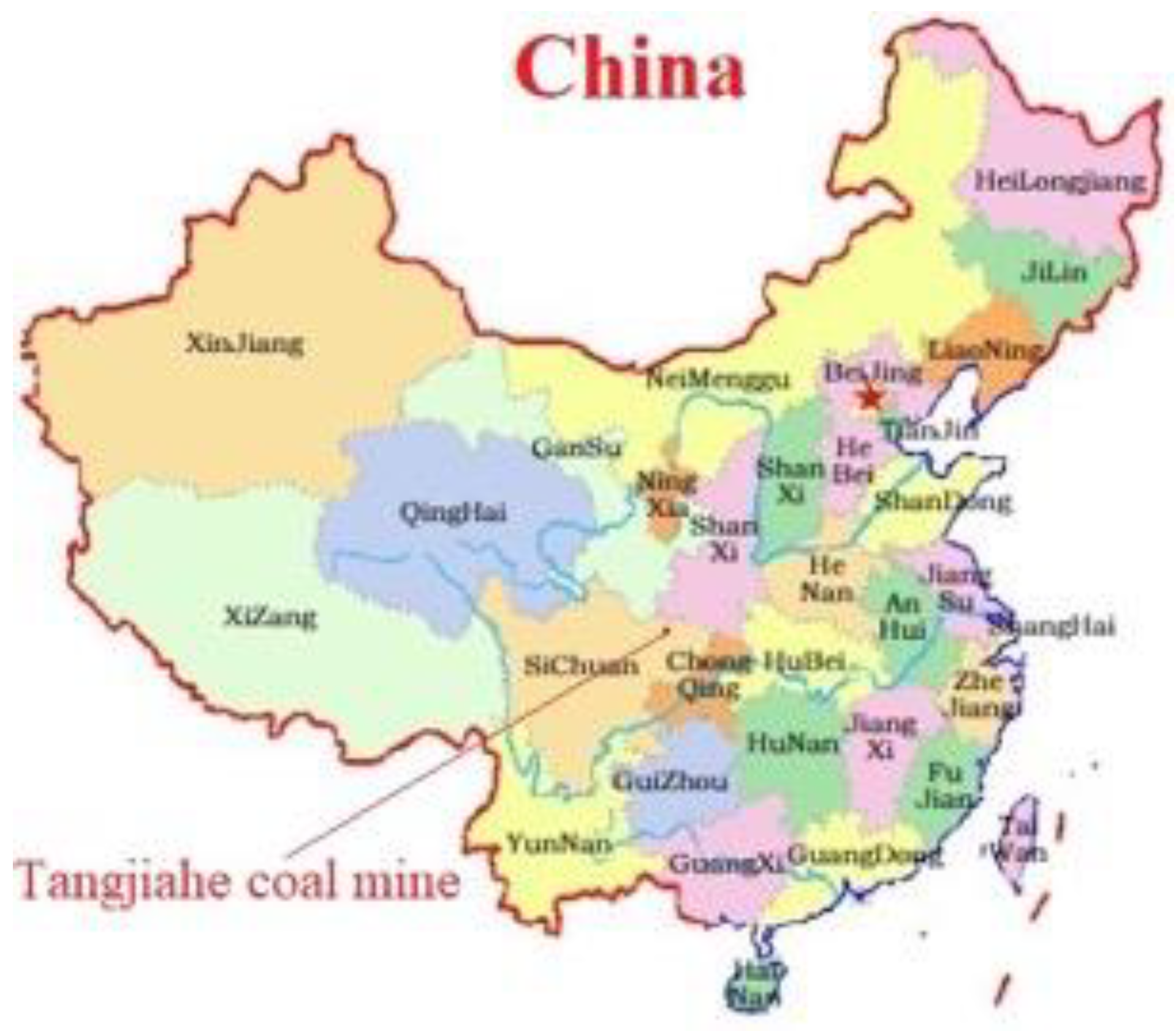
The Tangjiahe coal mine is located in the north of Qingchuan prefecture, Guangyuan city, Sichuan province, China (
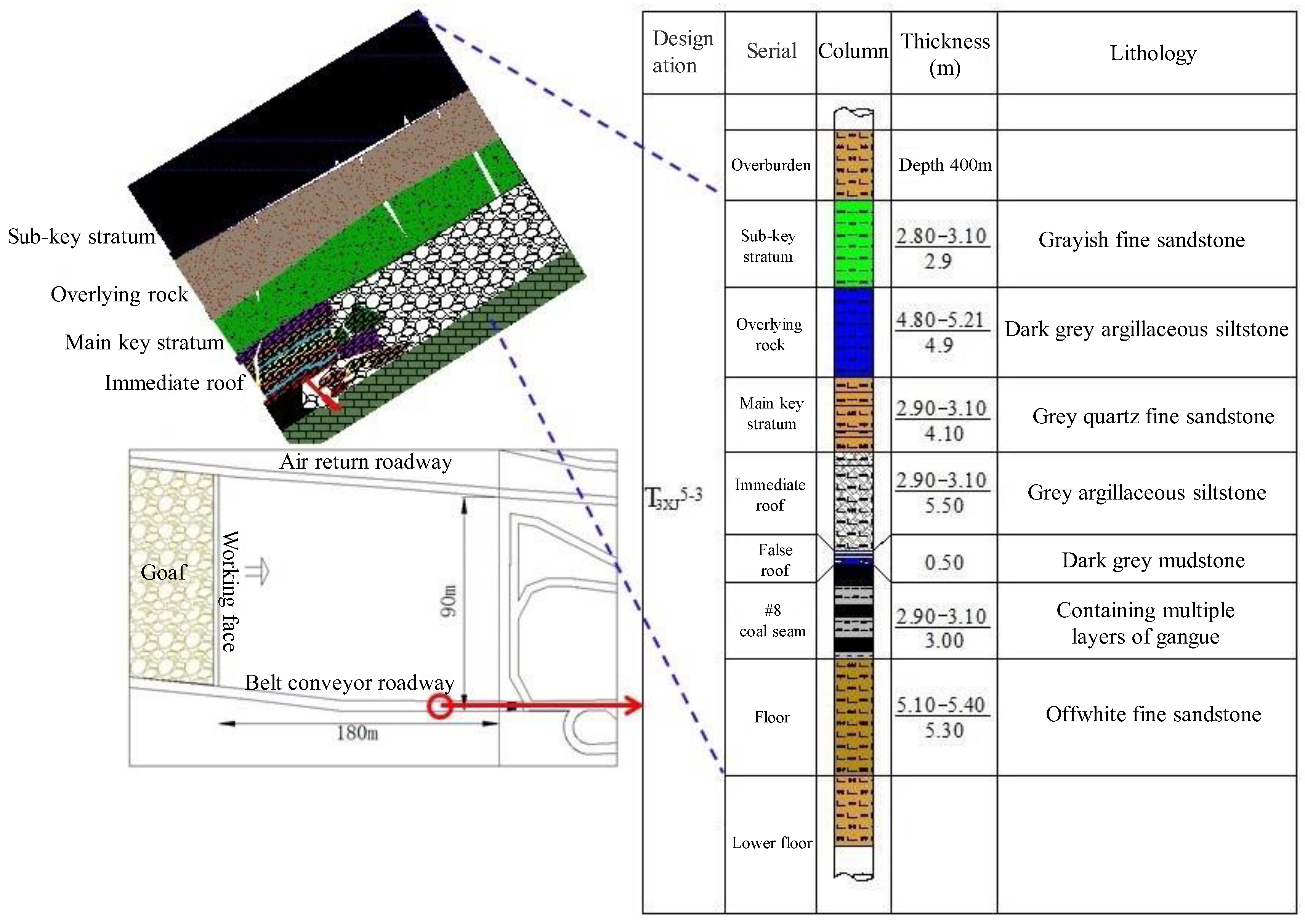
Figure 1). The detailed stratigraphic column and the layout plan of the roadway are shown in
Figure 2. The eight coal layer of this mine is at the bottom of the third sub-segment in
Section 5 of the Xujiahe formation of the upper Triassic (T
3xj
5-3); this coal seam is the primary mineable coal bed of the Tangjiahe coal mine, and it has a thickness of 1.2–3.2 m and a coal seam dip angle of 45°. The false roof is argillaceous siltstone mixed with coal dust with a thickness ranging from 0.1 to 0.3 m, the immediate roof is argillaceous siltstone with a thickness of 2.0–4.0 m, and the upper roof is fine sandstone with a thickness of 4.0–7.0 m. The immediate floor is argillaceous siltstone with a thickness of 0.2–0.4 m, and the lower floor is argillaceous siltstone or siltstone with an approximate thickness of 5.0 m.
2.2. Roof and Wall Collapse Accident
On 12th September 2014, a geological structure was encountered when the #1813 fully-mechanized coal mining face of the Tangjiahe coal mine reached the distance of 80 m to the open-off cut. The coal seam floor was on an average slope of 12°, and the partial section had a slope of 20°. The influencing length on the inclination direction was 35 m, and the roof of the coal seam in this area was extremely fractured. Because the slope of the working face was relatively large at 14°, wall spalling occurred from the 72nd to the 100th support on the working face and collapsed with a width varying from 3.0 to 8.0 m. After the wall spalling, a roof fall followed because the newly exposed roof could not be supported in time; the inclination length of the roof fall was 42 m across a height of 3.0–8.0 m and an area of 270 m2. Supports and coal cutters were buried by the collapsed gangue and production on the working face had to cease.
2.3. Countermeasures
This roof collapse and wall spalling affected a large area and resulted in deep wall spalling, a considerable roof collapse height, and large inclination of the working face. A large amount of gangue, which is the solid waste that is discharged from coal mining process [
22], fell to the bottom of the working face, which complicated gangue cleaning. Thus, the traditional approach of laying a fake roof by using timber crib and erecting H-steel was not suitable; high-polymer material consolidation and filling were considered instead.
2.4. Characteristics of High-Polymer Material
High-polymer materials can be divided into four types based on function: (1) filling material to discharge the gas accumulated in the roof falling area, (2) solidification material to solidify the collapsed roof and wall gangue, (3) consolidation material to consolidate the front coal wall to prevent further roof collapse and wall spalling, and (4) water sealing material. The environment of the working face in the coal mine is relatively complex, with many dangerous resources including gas and sulfur-containing coal. To protect the mine workers, high-polymer material used on the working face must have the following characteristics: (1) The gas produced by the chemical reaction of the material cannot be poisonous, harmful, or excitant; (2) the exothermic temperature of the reaction should be either low or nonexistent; (3) the material should have stable mechanical properties; and (4) molecular particles should have good diffusivity in the coal.
Based on the above principles and field requirements of the working face, mixed materials of HASF-2/20 and DN-1 were selected.
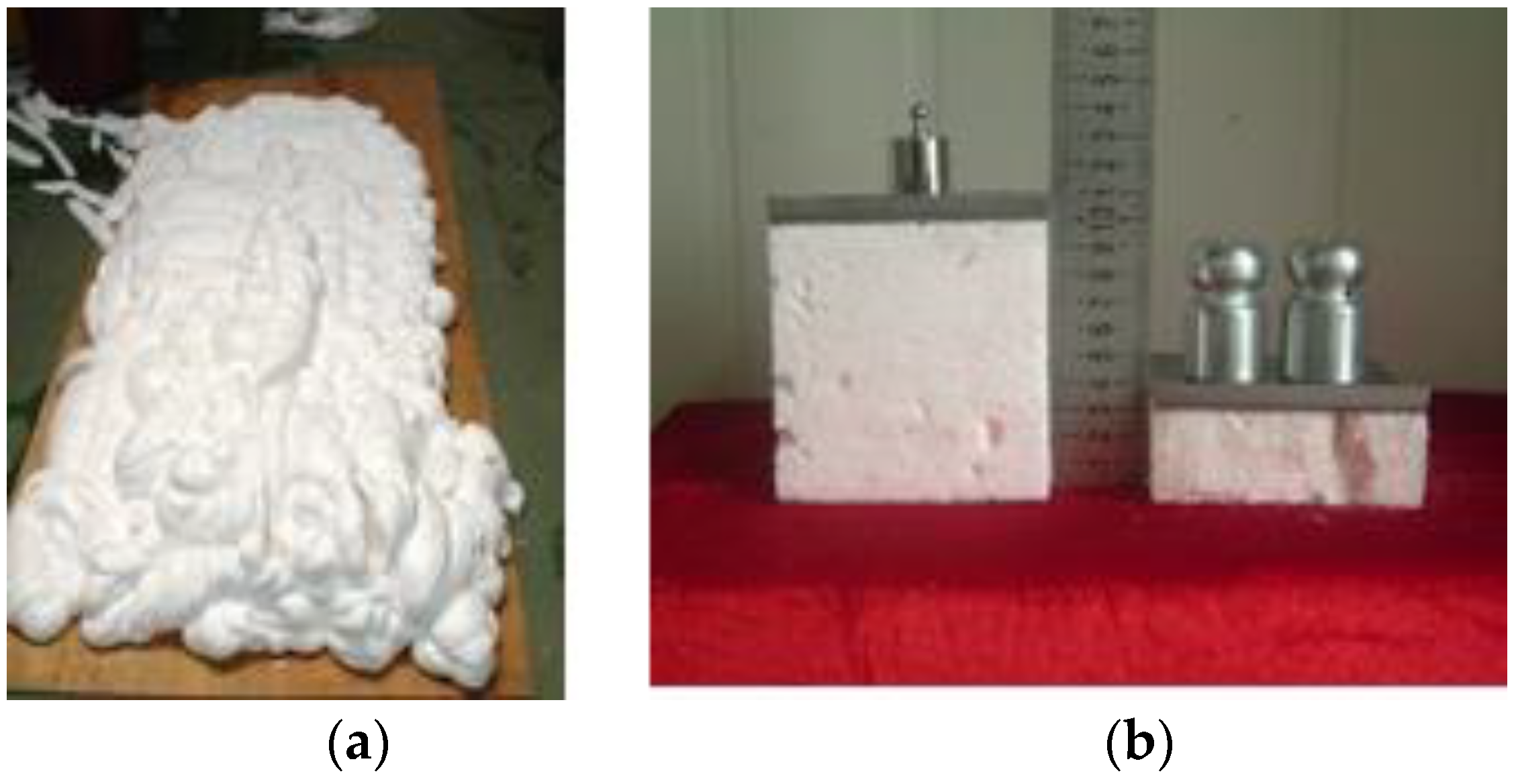
The mixed HASF-2/20 and DN-1 have an endothermic reaction after mixing, forming a 30-time hermetic foam that is stable and does not collapse. The foam can quickly fill collapsed openings and discharges accumulated gas. The expansion effect and the solidified foam are shown in
Figure 3.
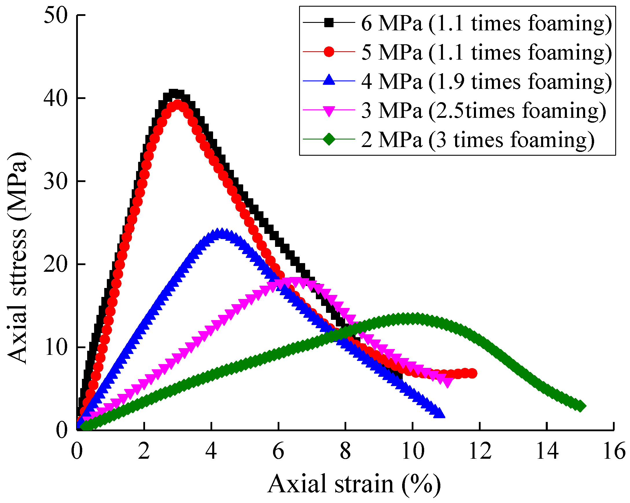
Compressive strength is an important indicator of the performance of the grouting-consolidated material. The grouting pressure exerts a large influence on the reaction speed, the foaming ratio after the HASF-2/20 and DN-1 are mixed, and the final strength.
Figure 4 shows the material strength curve for different grouting pressures. In general, as grouting pressure increases, the material foaming ratio decreases and the compressive strength increases. When the grouting pressure surpasses 5 MPa, the material reaction foaming ratio remains at 1.1 and a small increment is observed. The five different grouting pressures lead to four foaming ratios, at which the material with a higher foaming ratio shows a larger axial strain under the same compressive strength. The critical strain value
εp also increases along with the foaming ratio. Compared with the coal and rock specimens, the consolidation material specimen exhibits no initial compression phase and the elastic stage lasts until the peak. Lastly, the higher the foaming ratio, the smaller the slope of the stress curve is after the peak.
3. Materials and Methods
The filling material was used in the collapsed roof zone for the reinforcement of the fractured gangue in the caving zone, and of the front coal wall and roof. The consolidation effect of the high-polymer material on the caving gangue is mainly reflected in the consolidation of separate and discrete gangues into a whole with gangue as the aggregate and the high-polymer material as the skeleton by means of adhesion. The reinforcement of the coal wall and roof is achieved by injecting the high-polymer material into the fractured rock mass to fill the fractures. Therefore, the experiments presented in this study were performed on grouted gangue and grouted single-fractured coal and rock.
3.1. Grouted Gangue Specimen
Carbon mudstone gangue was selected: It is flaky with angular edges and has low compressive strength and high discreteness. The gangue samples were placed into containers (confining pressure
P0 = 0), and the grouting pressure of
p = 2 MPa was the same as in the field for gangue solidification as shown in
Figure 5. Standard specimens of 50 mm diameter and 10 mm height were cored after curing for 1 h under ambient temperature conditions.
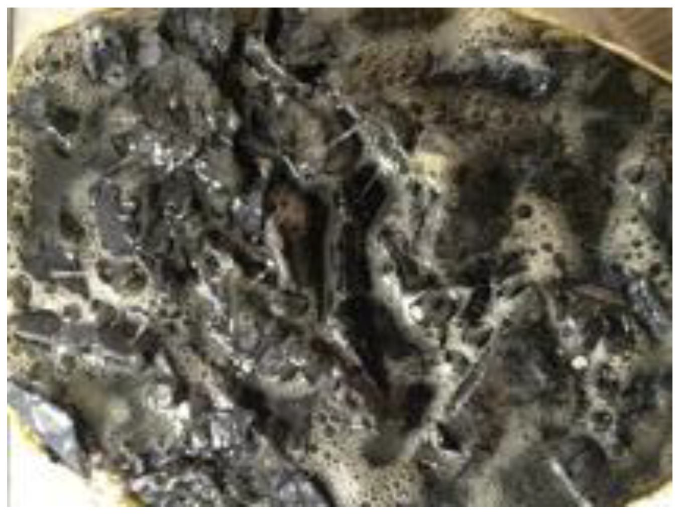
Figure 6 shows the standard solidified specimens with different grout proportions. Three grouted gangue specimens with grout proportions of 6%, 9%, and 13% were tested to determine the influence of the grout proportion on the mechanical properties of the grouted specimens.
3.2. Consolidated Single-Fractured Coal and Rock
During rock solidification engineering, damage from the stress field on the rock structure is manifested as compound damage, including tension, compression, and shear; all of these cause the discreteness and fracture of the rock mass. Subsequent problems include irregular fractures and difficulty in obtaining samples. Theoretically, the consolidation of coal and rock walls when using a high-polymer material can lead to the penetration of the material along with the fractures and openings during solidification. In the laboratory, after prefabricating fractures in the coal and siltstone blocks [
23], the samples were bonded and consolidated by the high-polymer material under a grouting pressure of
p = 5 MPa.
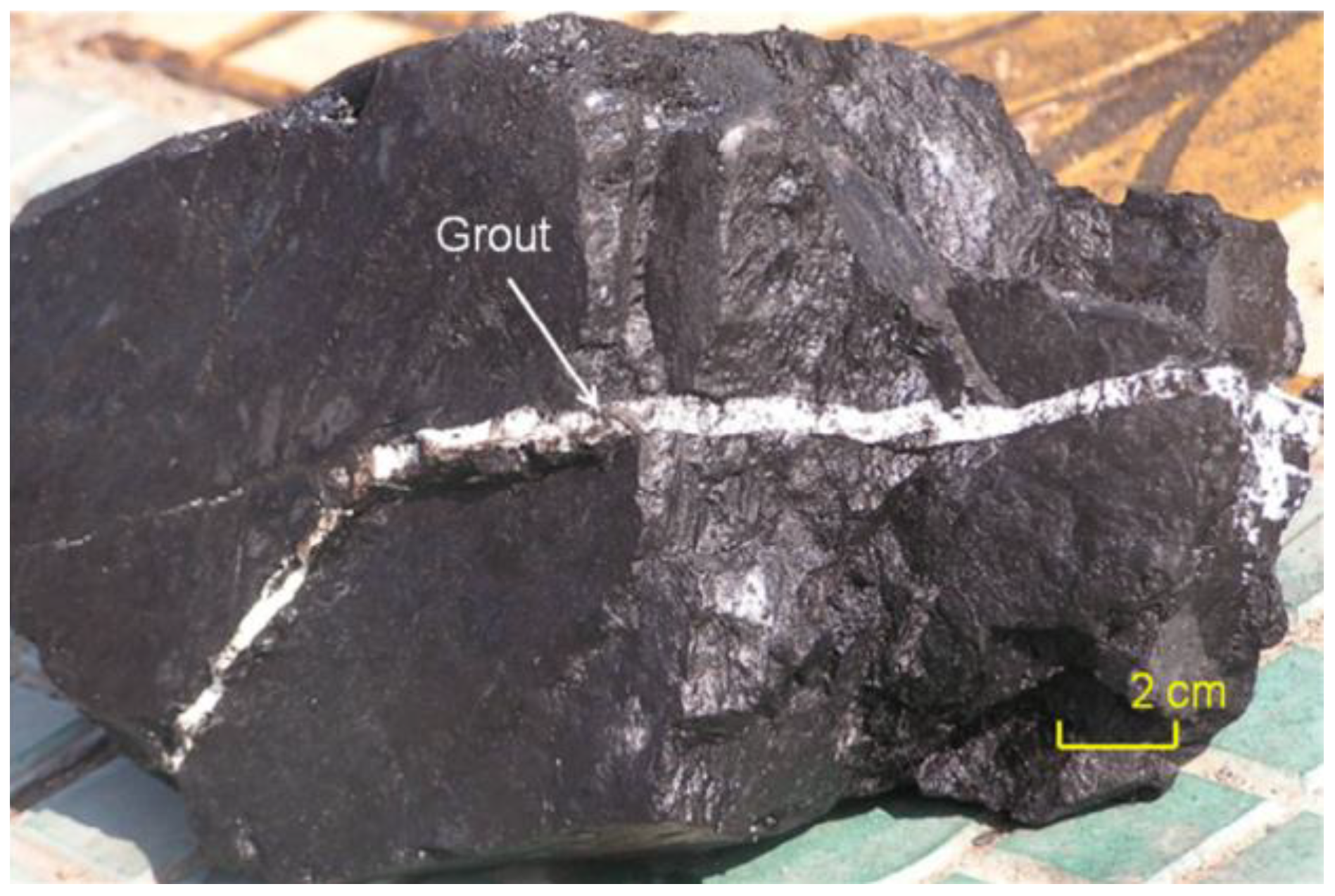
Figure 7 shows the fracture filled with the injected high-polymer material to strengthen the fractured coal. After curing for 1 h, the consolidated siltstone masses were cored parallel and perpendicular to the fracture into cylinder specimens of 50 mm diameter and 10 mm height, as shown in
Figure 8. The consolidated specimens had vertical and horizontal fractures that were filled with the high-polymer material in the consolidated face of the coal and siltstone specimens. All specimens had the same consolidated face thickness. Therefore, the solidification of a single-fracture was used to understand the grout propagation in the fracture network.
4. Results of Grouted Gangue
4.1. Mechanical Characteristics
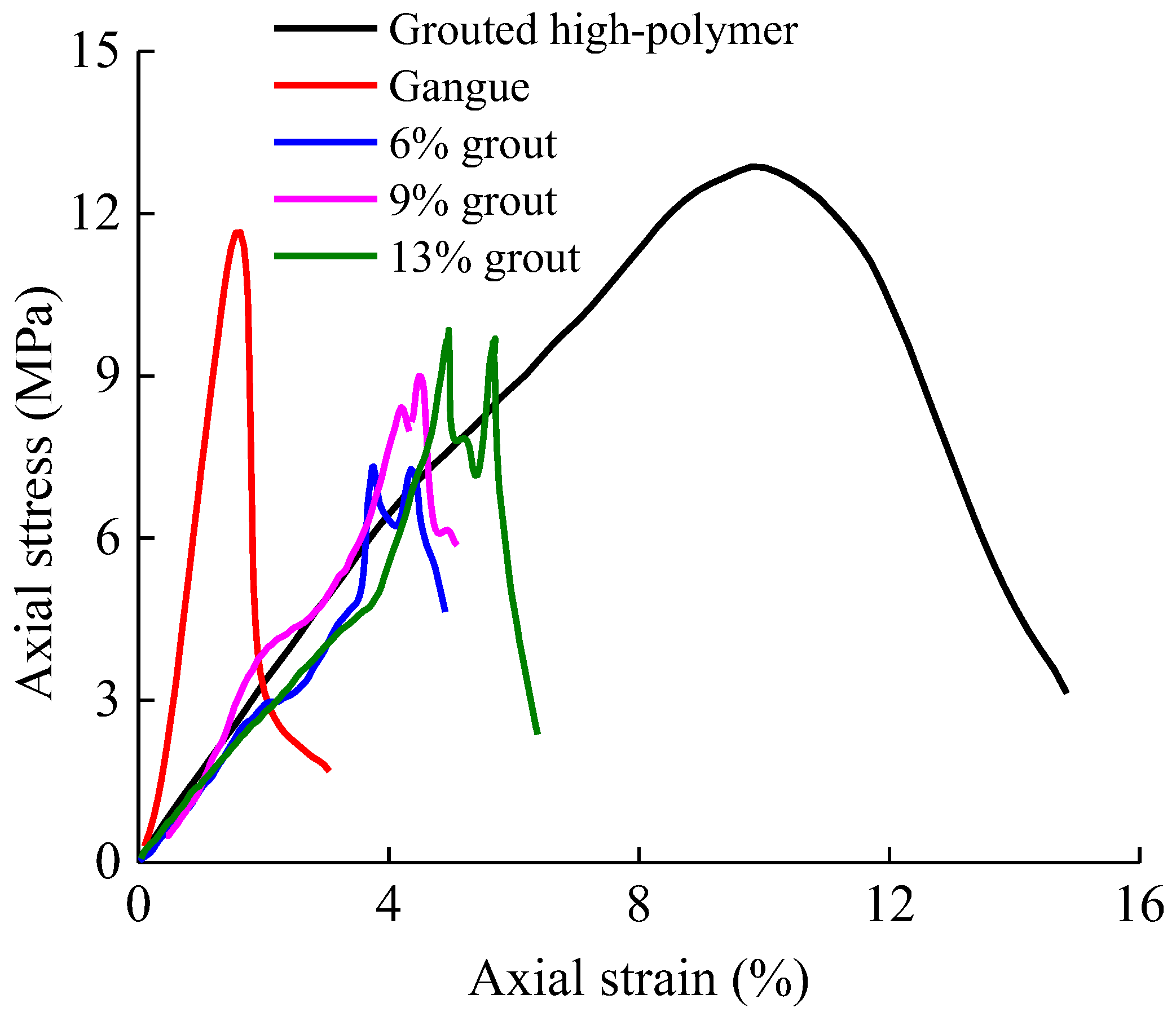
Three grouted gangue specimens, one gangue specimen, and one grouted high-polymer specimen were tested with a uniaxial compression test. According to the stress–strain curves shown in
Figure 9, the grouted gangue specimens exhibited non-linear behavior as a result of the interaction between the grout and the gangue in the mechanical process [
24]. The compressive mechanical characteristics were manifested as the interaction between the grout material and the gangue and the yield and weakening of the internal defects.
The axial stress–strain curves were divided into four sections based on the interaction between the grout material and the gangue: the elastic stage (grout-dominating stage), the partial yielding stage (gangue-dominating stage), the yielding stage (interaction-dominating stage), and the post-damage stage. In the elastic stage, the grout material dominated the mechanical properties. In the partial yielding stage, during the specimen compression, the gangues came into contact with each other and caused the local stress to become larger than the tensile and shear strength; this pattern led to some microscopic damage, and some shifts occurred among the particles around the fractures, resulting in a reduction in the stress. At this point, a large extrusion force was generated as a result of the interaction of the gangues, leading to an increase in the rate of the stress–strain curve. In the yielding stage, the curve exhibited bimodal behavior. Shear and splitting failure occurred in the area of dense distributions of gangue or in the area of flaky gangues, leading to a rapid release of strain energy and a rapid reduction in the stress. Restricted by the grout material, the gangue rejoined and then the second peak appeared, but it was clearly lower than the first peak. The damage stage followed the second peak; after repeated stress release and mutual shift, the stress declined rapidly.
The gangue specimen had an elasticity modulus of 705 MPa, a Poisson’s ratio of 0.21, and a uniaxial compressive strength of 11.8 MPa. The high-polymer grout material specimen had an elasticity modulus of 135 MPa, a Poisson’s ratio of 0.36, and a uniaxial compressive strength of 13.5 MPa. The compressive strength of the grouted gangue specimen was clearly greater than that of the gangue specimen. The elasticity modulus of the gangue specimen was 5.2 times that of the grout specimen, and the Poisson’s ratio of the gangue specimen was 0.58 times that of the grout specimen; thus, under the same pressure, the axial and radial deformation and expansion volume of the grout were much greater than that of the gangue. Furthermore, the stress–strain curve of the gangue exhibited the typical features of a stress–strain curve of rock under uniaxial compression with a clear void and crack compaction stage and brittle drop after the peak. The stress–strain curve of the uniaxial compression demonstrated no void and crack compaction stage and directly entered the elastic stage after being compressed; additionally, the slope of the stress–strain curve after the peak was relatively gentle. The gangue specimen exhibited brittle fracture, whereas the grout specimen exhibited ductile fracture.
After the gangue specimen was grouted with the high-polymer material, the high-polymer material covered and bonded the gangue, exhibiting a combination of the mechanical properties of the high-polymer material and the gangue in terms of general anisotropy and ductility.
The high-polymer material facilitated the bonding of the gangue particles after penetrating the openings of the gangues; thus, the mechanical properties of the grouted specimen were substantially enhanced. The liquid high-polymer material was grouted into the gangue and expanded and immediately solidified via chemical reactions; since the grain size and voids of the gangue specimens differed, the required amount of the high-polymer material and the mechanical properties of the specimens were distinct in several ways. First, the larger grout proportion of the high-polymer material connected more gangue particles and led to a greater strength, as well as greater ductility and bimodal behavior, of the grouted specimen. Second, almost no interlocking action appeared for the uniform graded specimen. The cohesive force of the skeleton limited the relative gangue sliding; a larger grout proportion that connected more of the gangue skeleton produced a longer elastic stage under compression. Third, the larger grout proportion caused a gentler curve prior to the peak, indicating the presence of fewer defects inside the specimen.
The high-polymer material possessed better solidification efficiency and higher strength than the grouted rockfill [
24,
25]. Zhang et al. [
26] conducted shear tests of high-polymer-grouted specimens and observed an increasing trend of cohesion and friction angle with increasing proportion of the high-polymer material (
Table 1). As the grout proportion increased, the cohesion and internal friction angle of the specimen increased. The specimens with more grout proportion had relatively higher cohesion and internal friction angle, indicating that the high-polymer material adhered well around the gangue.
4.2. Damage Pattern
The uniform graded aggregate showed no obvious interlocking effect. The openings of the aggregate were filled by the high-polymer material to form a whole unit with the grout as the skeleton and the gangue as the aggregate after the solidification reaction.
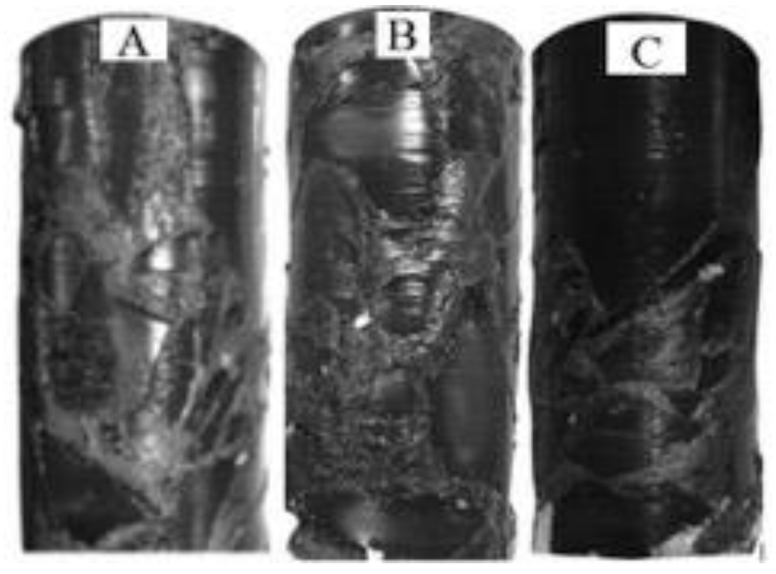
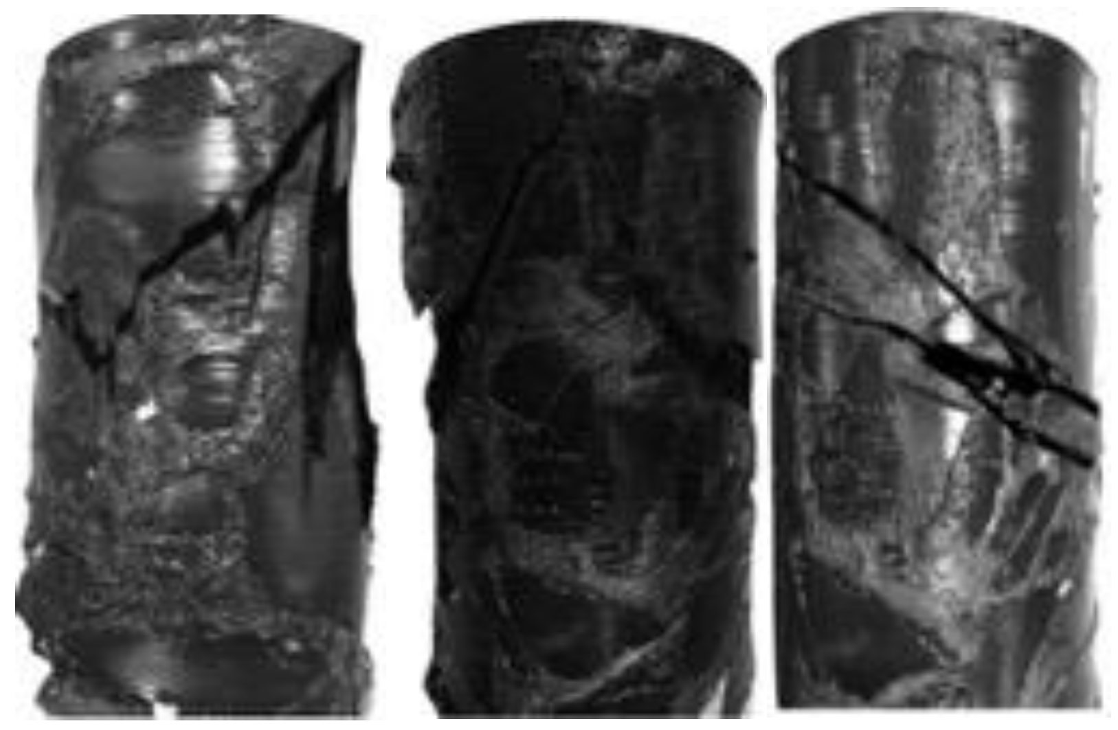
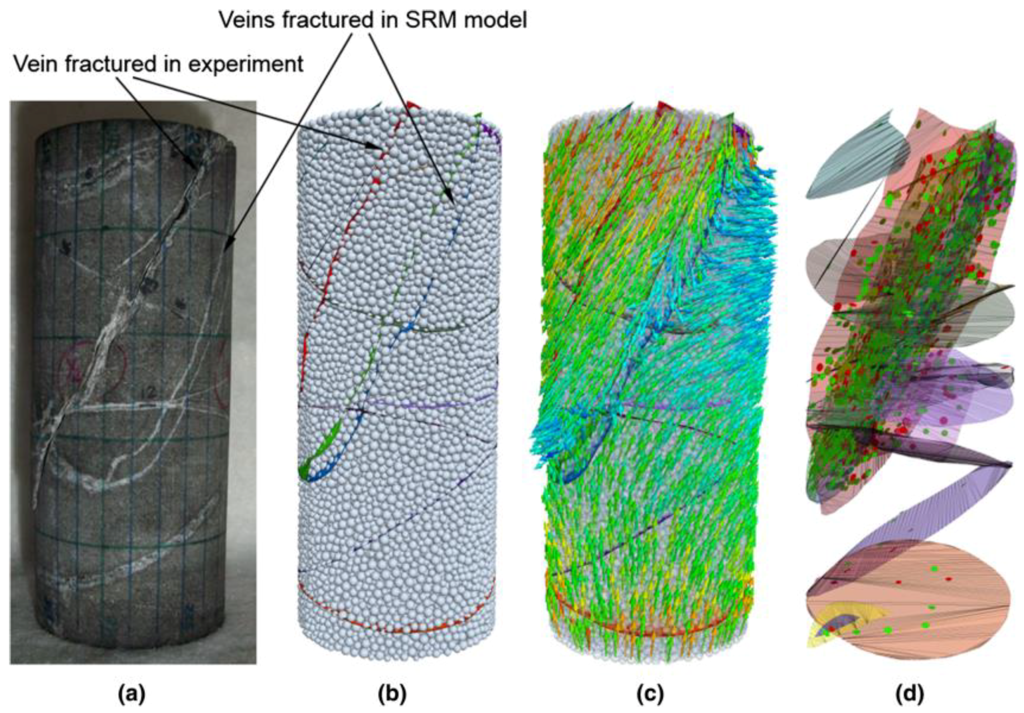
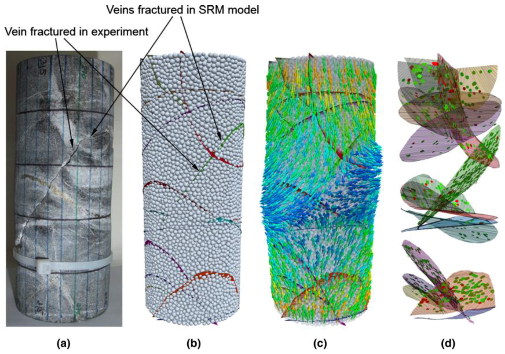
Figure 10 shows the damage patterns of the three grouted gangue specimens. As the solidification material proportion changed, the damage patterns changed. Due to the influence of the anisotropy of the specimens, through-splitting damage from top to bottom would normally not occur; instead, shear failure typically appeared along a relatively weak cementation face or directly through the flake gangue. Since the strength of a material is usually governed by the weakest portion, the large amount of pre-existing weak cementation face makes the grouted gangue more prone to fragmentation. Turichshev and Hadjigeorgiou [
27] demonstrated that an intact veined rock specimen failed along a vein, as shown in
Figure 11 and
Figure 12, and concluded that the weakest mechanical link in the system determines the overall strength.
Along with the load and deformation of the specimens, the skeleton was first compacted, followed by stress concentration surrounding the gangue. As the gangue shifted during the deformation process, the force chain was developed and fractured over again and again, and a combined shear and tension damage mode gradually occurred. Slippage damage was observed along the contact interface, leading to more significant interior shear zones and splitting zones that exacerbated the degradation of the specimens; hence, the compressive strength of the grouted gangue specimens did not reach the compressive strength of either the high-polymer material specimen or the gangue specimen. The limitation of the high-polymer material, as well as the contact and interlocking of the gangues, led to the development and extension of multiple cracks. This pattern also explains the formation of the two peaks in the stress–strain curve of the grouted specimens.
The damage patterns of the specimens with different grout proportions varied. As with the loading, the damage pattern of the specimen with a grout proportion of 6% manifested as a flexural crack through most specimens with a local collapse, similar to local tensile splitting damage as a whole unit. The damage plane essentially mimicked the contact interface of the high-polymer material and gangue, whereas the specimens with the grout proportions of 9% and 13% exhibited nearly no local collapses, and a crack developed through part of the gangue and resulted in local shear damage. The mechanical strength and deformation properties of the grouted gangue specimens were hence related to the properties of the gangue and high-polymer material, as well as to the amount of high-polymer material.
4.3. Discussion
The solidification effect of the high-polymer material on the loose gangue fragments substantially increased the bearing capacity of the gangues. The gangue grain size, porosity, and spatial distribution resulted in different dosages of the high-polymer material and in diverse damage patterns, forms, and mechanical properties of the solidified specimens. The results of the uniaxial tests indicated that when the quantity of the high-polymer material was relatively small (6%), the compressive strength of the specimen was small, and the damage plane occurred around the gangue surface. The generation and development of the damage plane extended around the gangue, mostly expanding along the cementation plane as portions of the material broke off. When the quantity of the high-polymer material was large (13%), the compressive strength of the specimens markedly increased to 10.5 MPa. A strong strain energy release followed the specimen damage once the crack penetrated the gangue. Due to the good adhesion of the high-polymer material to the gangue, the cohesion and internal friction angle increased among the gangue blocks, increasing the specimen strength.
5. Results of Consolidated Single-Fractured Coal and Rock
The effects of the high-polymer material on the coal and rock specimens were the same, revealing a substantial increase in the completeness of the fractured coal and rock mass and thus increasing the overall mechanical properties. Based on the mechanical property differences among the coal and rock and the different adhesion areas of the material, the specimens exhibited different mechanical properties and damage behavior after the high-polymer material consolidated the coal and rock mass.
5.1. Mechanical Characteristics
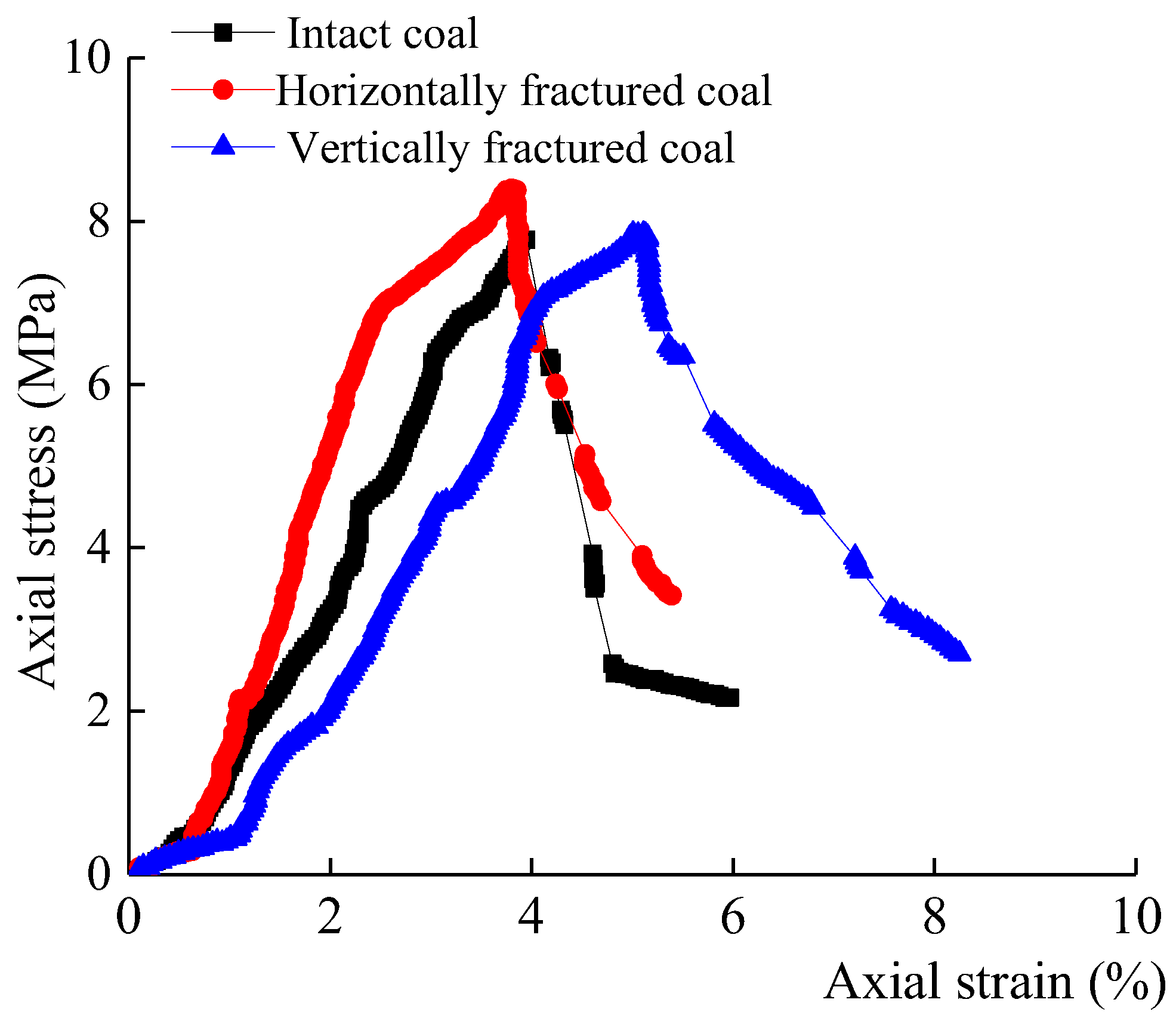
Figure 13 presents the stress–strain curves of the three coal specimens with different fracture distributions in the uniaxial tests. The consolidation of the coal and siltstone specimens with the high-polymer material significantly increased the peak strength of the specimens. When reaching the damage stage, the peak strength of the intact coal specimen was 7.9 MPa, that of the horizontally fractured coal was 8.9 MPa, and that of the vertically fractured coal was 8.4 MPa. Due to different consolidated fracture positions, the strengths of the horizontally and vertically fractured coal were increased by 13% and 6%, respectively, as compared to those of the intact coal. Given the increased residual strength after the peak, the axial stress of the coal and siltstone specimen rapidly declined after reaching the peak. The stress drop diminished after the peak for the consolidated fractured specimen due to the solidification effect of the high-polymer material.
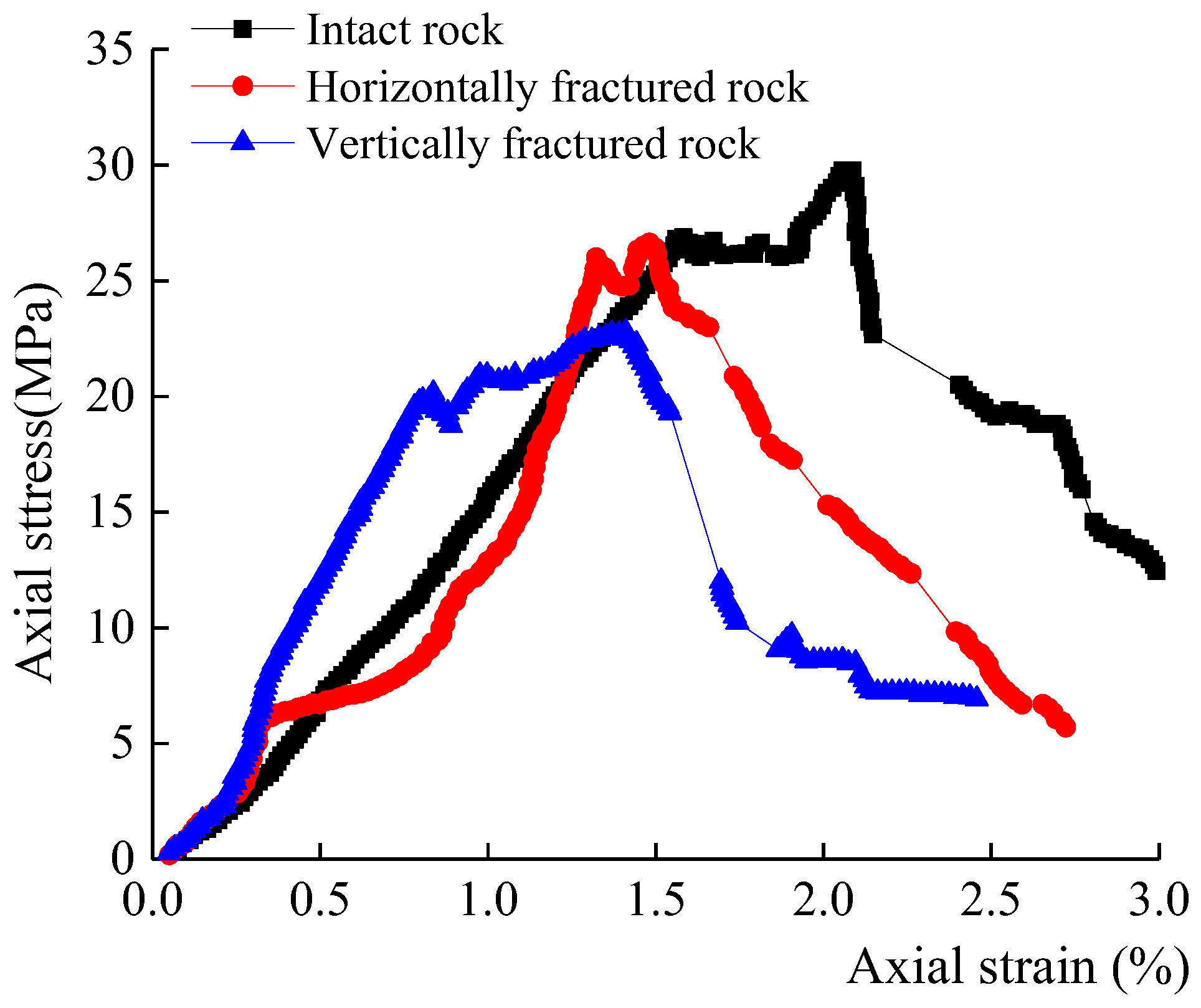
Figure 14 shows the stress–strain curves of the three siltstone specimens with different fracture distributions. The peak strength of the intact siltstone specimen was greater than that of the consolidated specimens; the peak strengths of the specimens with horizontally- and vertically-consolidated fracture were decreased by 13.4% and 26.8%, respectively, as compared to those of the intact siltstone specimen. The siltstone specimen exhibited a dense structure without a discontinuity effect, and the increase in the stress–strain curve was relatively gentle without large fluctuations. Obvious fluctuations occurred in the increasing stage of the stress–strain curve for the consolidated fractured specimen, along with a deviation from the curve of the siltstone specimen.
A comparison of the test results of the coal and siltstone mass consolidation indicates that the high-polymer material had different effects on the coal mass and siltstone mass. When the mechanical property of the specimen was weaker than that of the high-polymer material, the rock mass that was consolidated with the high-polymer material was regarded as that of a strong steel bar. The bonding effect of the high-polymer material partially limited the lateral displacement of the rock mass and changed the unidirectional stress state of the original specimen into a tri-directional stress state, increasing the uniaxial compressive strength of the consolidated specimen. The incongruous response of the stress and strain between the interior high-polymer material and the coal/siltstone part in the compression test of the consolidated specimen resulted in the generation of residual stress in the specimen after the peak. However, when the mechanical properties of the specimen were similar to that of the rock, the high-polymer material layer was not able to limit the displacement of the rock specimen. Given the differences in the mechanical properties of the high-polymer material and the rock which represented the weak portion of the specimen, the mechanical strength of the consolidated rock specimen could not recover to that of the complete specimen.
5.2. Damage Pattern
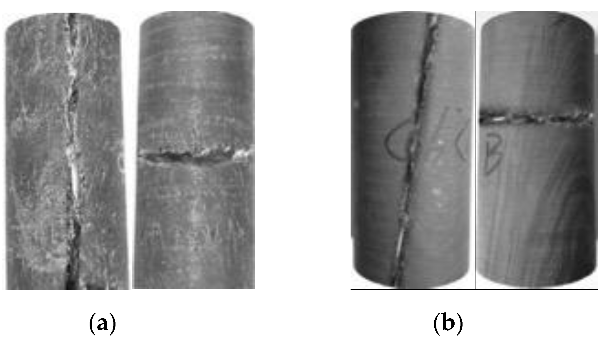
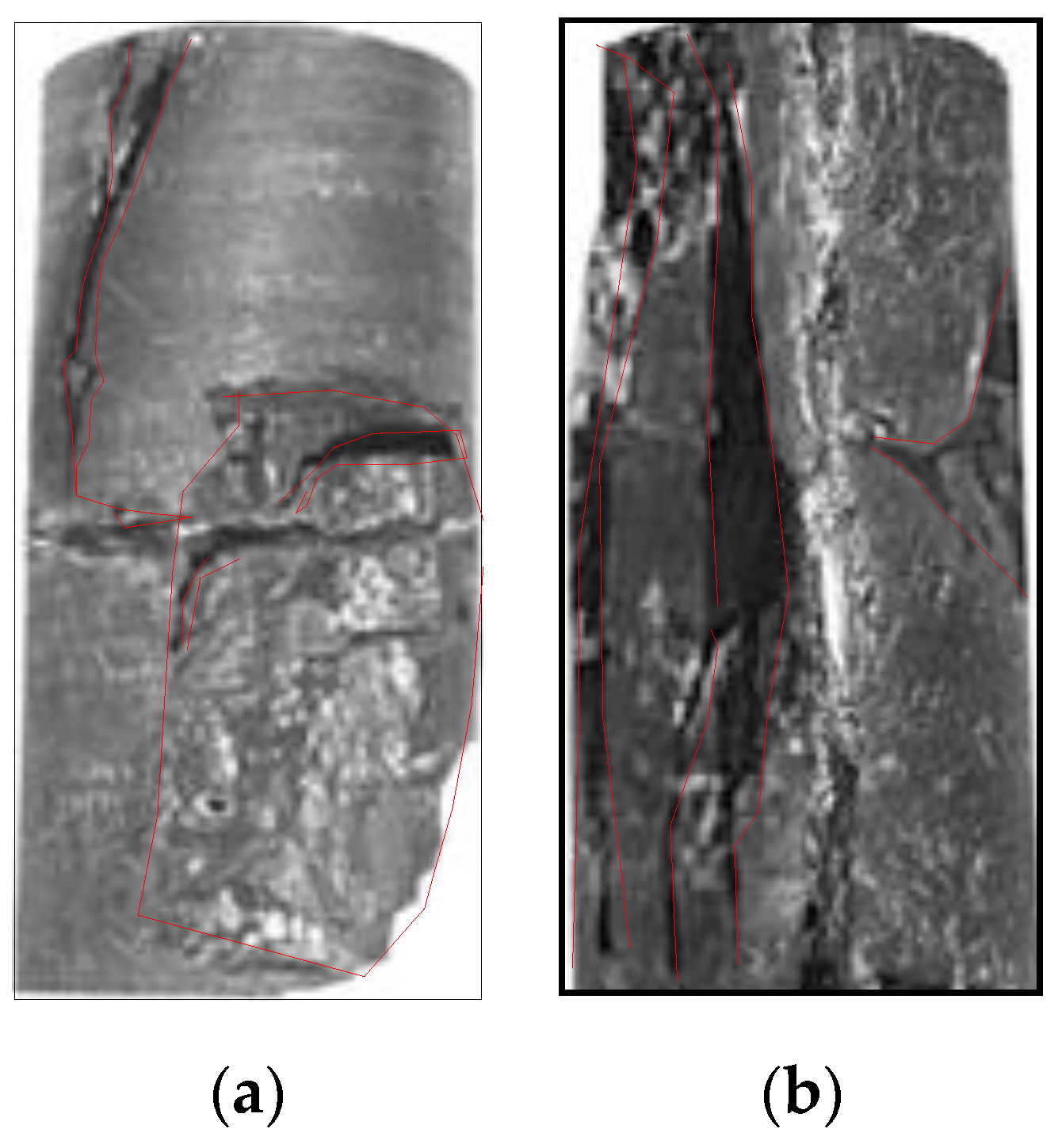
The bonding effect of the high-polymer material transformed the fractured coal/siltstone mass into a complete system, resulting in a damage process with more complex crack initiation, extension, and cut-through behavior than in the intact coal/siltstone specimens. A comparison of
Figure 15a,b indicates that no vertical through-going cracks occurred in the horizontally-consolidated specimens due to the obstruction of the high-polymer material layer. The cracks in the vertically-consolidated specimens showed vertical through-going cracks. For the both horizontally- and vertically-consolidated coal mass under uniaxial compression, cracks of the coal mass developed and extended into the coal mass; after a certain distance, cracking along the boundary of gangue occurred near the high-polymer material layer.
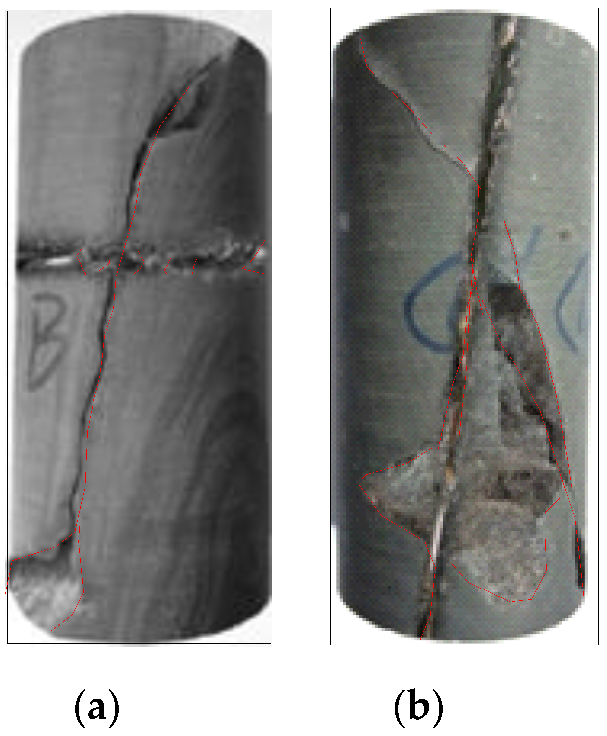
Figure 16a,b shows that both consolidation types exhibited through-going cracks. The cracks first developed in the high-polymer material layer and then became through-going cracks during the compression process.
6. Fracture Mechanism Analysis
Many geotechnical engineering practices and tests results have shown that rock stability is closely related to the initiation of fractures. Failure in geotechnical engineering is often caused by the development, extension, and coalescence of the original joint cracks. Fracture structures are important components of the microstructure of materials that are consolidated by grouting. The development of openings and cracks has a considerable microscopic influence on materials.
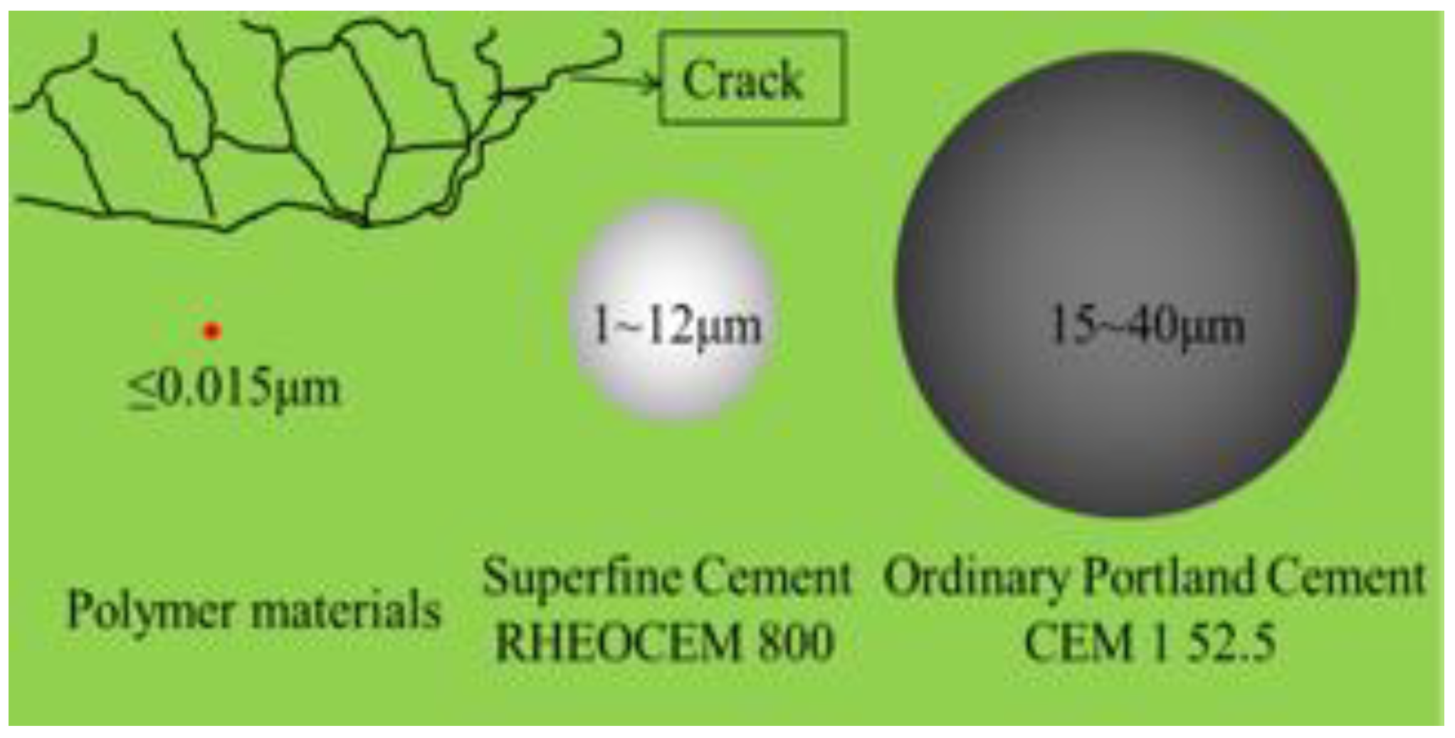
As shown in
Figure 17, compared to common and fine cement grouts, the grain size was smaller for high-polymer materials. After the high-pressure grouting of the rock mass, this high-polymer material easily diffused, gelatinized, and solidifies in the microcracks and openings, and it integrated the coal/rock mass, reduced the stress concentration from the crack tips, and increased the coal/rock mass strength.
In essence, the mechanisms of rock consolidation by the high-polymer material were the same as that of the other cemented materials; cracks preferentially appeared in the weak plane of the structure. The structure resulting from the integration of the high-polymer material and the rock mass exhibited a complex stress–strain relationship during the uniaxial compression test due to the bonding effect between the high-polymer material and the rock; damage easily occurred in the weak plane and led to restrictive crack development and extension. In the uniaxial compression tests, the solidified and consolidated specimens constituted a complete structure, including the structure plane. After comprehensively considering the deformation and the physical and mechanical properties of the high-polymer material and cementation plane, Xian [
28] established expressions for the bonding stresses at the interface based on the deformation continuity. For specimens with the global coordinates
Z0 X0 Y0, the expressions for the bonding stress at the interface of the high-polymer material with the local coordinates
zxy were determined by using a coordinate transformation.
The stress matrix for the global coordinates is:
and the bonding stress expressions for the consolidated material near the interface in local coordinates are:
where
i,
j, and
k denote the unit matrix related to the coordinate transformation, respectively, and
k1–
k4 are the material parameters with the following expressions:
where
EA,
EB,
μA, and
μB denote the elasticity modulus and the Poisson’s ratio of the gangue and cementation, respectively.
Combined with Equations (1) and (2), the bonding stress expressions in local coordinates for the consolidated material adjacent to the interface are as follows:
According to Equation (4), given the stress state in the consolidated material adjacent to the interface in local coordinates, tensile stress occurs in the x and y directions, and shear stress occurs in the x-direction. Therefore, tensile–shear cracks will likely initiate in the zone of the consolidated material that adjoins the interface and then propagate to the nearby upper and lower regions. The bond stress at the interface was thus controlled by the weak phase material, and cracks were more likely generated in the weak plane first before developing along that plane and wedging out around the strong phase plane.
7. Field Applications
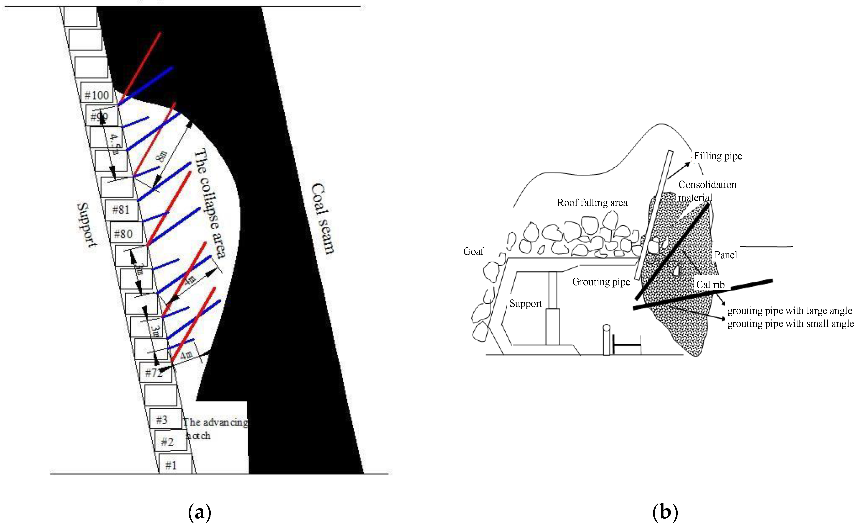
The experimental tests demonstrated the good performance of the high-polymer material regarding the solidification and consolidation of the coal mass and rock mass; actual field applications were conducted thereafter in the Tangjiahe coal mine. The distribution of the grouting holes is shown in
Figure 18.
(1) Filling the Collapsed Area
The construction sequence for creating the grouting holes proceeded from low to high; one filling hole was created for every three supports (4.5 m), the hole was located on the roof of the junction of the forepoling, and the face guard and was inclined at 70° against the wall. The end of the hole was at the top of the roof fall area, and the grouting pipe was 500 mm below the top. If the roof fall area was more than 8 m, this hole was considered a deep filling hole, and the setting depth of the grouting pipe was at least 6 m. The grout quantity was adjusted according to the field grout leakage. If the grout leakage was directly proportional to the injection quantity or reached the designed grouting pressure, the grouting was completed for this hole; at this point, we moved to the next hole until all grouting work was completed.
(2) Solidification of the Collapsed Gangue Area
The grouting holes for the gangue solidification included two types: large-angle (45°) grouting holes and small-angle (10°) grouting holes. The large-angle grouting holes were 500 mm below the roof and 4 m deep, and the grouting pipe was 3 m long. The hole of the small-angle grouting holes was under the face guard with a depth of 4 m, and the grouting pipe was 3 m long. For both large and small-angle grouting holes, one grouting hole was drilled per every two supports (3 m), resulting in six grouting holes for 10 supports. These consolidation grouting holes were distributed in a staggered arrangement so that the small-angle grouting hole was in the middle of large-angle grouting holes to facilitate a supplementary effect of the grout. The grouting holes were slightly adjusted depending on conditions to achieve a good consolidation effect. This construction scheme consisted of two cycles: after the initial grouting work, the working plane moved forward by 2 m, and the secondary grouting work began. If any leakage of the gangue occurred during the forwarding process, the supplementary grouting was completed in time.
(3) Coal Wall Consolidation
When the fully mechanized coal mining support moves across a gangue collapse area, the grouting and consolidation of the coal wall and rock mass should be carried out according to the distribution of the grouting holes to prevent a second wall spalling and roof collapse of the fractured coal and rock mass.
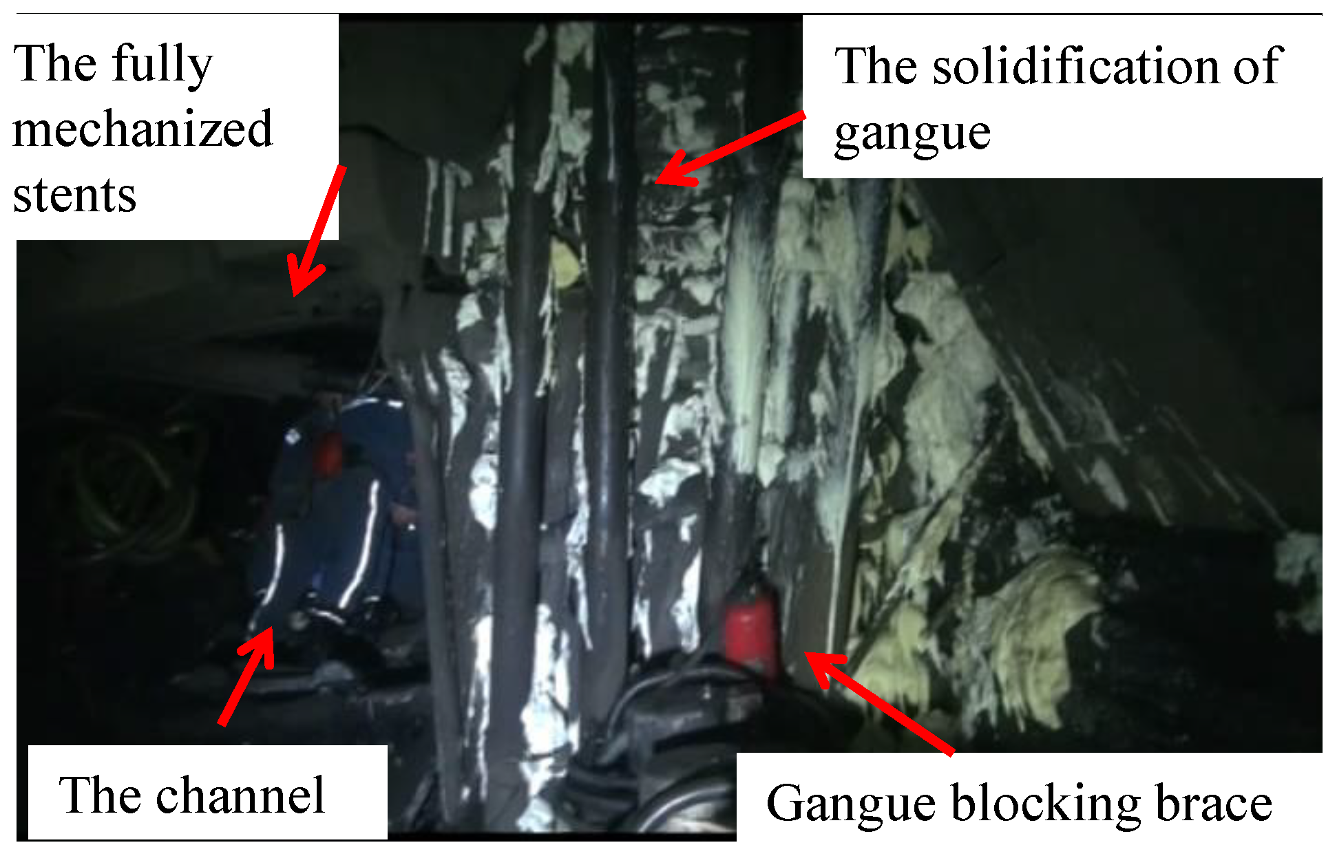
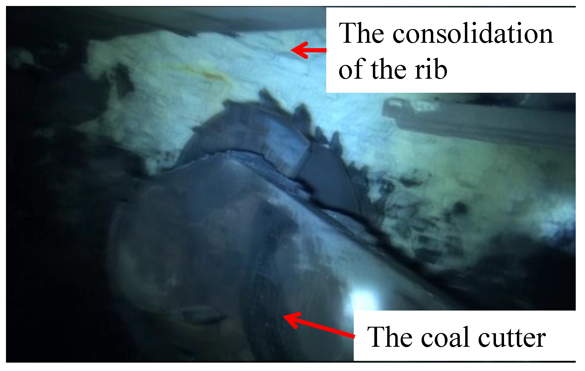
Figure 19 and
Figure 20 show photos of the field application of the grouting consolidation and solidification. It can be seen that the coal wall and the roof in front of the working face had good integrity. The coal wall was neat after cutting. Having been grouted, the stratum settlement was significantly mitigated and the stress state was leveled off. Consequently, the stope stability was greatly improved and the roof fall was effectively controlled. A good grouting effect had been achieved.
8. Conclusions
The use of a high-polymer material in a coal/rock mass can increase the integrity and mechanical strength of the coal/rock mass. Based on the mechanical response of the grouted specimens that used the high-polymer material, the following conclusions can be drawn:
- (1)
The mechanical properties of the consolidated specimens were influenced by the properties of the consolidation material and the gangue properties. The material dosage substantially influenced the mechanical properties of the specimens; the larger the amount of the high-polymer consolidation material, the greater the mechanical strength of the specimens was. When the dosage of the high-polymer material was relatively small (6% dosage), the damage plane was on the surface of the gangue and extended around the contact interface; the development and extension of the damage plane involved flexural passing around the gangue block. The damage usually extended along the cementation plane with the occurrence of detachments. When the dosage of the high-polymer material was large (13%), the damage plane partially extended across the gangue plane and developed further.
- (2)
If the strength of the high-polymer material layer exceeded that of the rock mass, the bonding effect of the material, acting as an anchoring effect, substantially increased the mechanical strength of the rock mass and limited the development of cracks after the peak stress. If the high-polymer material layer was the weak phase, the mechanical strength of the rock mass was weakened and cracks easily developed in the weak plane.
- (3)
The high-polymer material demonstrated good physical and mechanical properties regarding the solidification of the gangue and the consolidation of the coal and rock mass. This material shows potential for geotechnical engineering and mining engineering applications after field tests.


